User Manual
Bulletin 1336VTAdjustable Frequency AC Drive
Important User Information Because of the variety of uses for this equipment and because of thedifferences between this solid-state equipment and electromechanicalequipment, the user of and those responsible for applying this equipmentmust satisfy themselves as to the acceptability of each application and useof the equipment. In no event will Allen-Bradley Company be responsibleor liable for indirect or consequential damages resulting from the use orapplication of this equipment.
The illustrations shown in this manual are intended solely to illustrate thetext of this manual. Because of the many variables and requirementsassociated with any particular installation, the Allen-Bradley Companycannot assume responsibility or liability for actual use based upon theillustrative uses and applications.
No patent liability is assumed by Allen-Bradley Company with respect touse of information, circuits or equipment described in this text.
Reproduction of the content of this manual, in whole or in part, withoutwritten permission of the Allen-Bradley Company is prohibited.
The information in this manual is organized in numbered chapters. Readeach chapter in sequence and perform procedures when you are instructedto do so. Do not proceed to the next chapter until you have completed allprocedures.
Throughout this manual we use notes to make you aware of safetyconsiderations:
!ATTENTION: Identifies information about practices orcircumstances that can lead to personal injury or death, propertydamage or economic loss.
Attentions help you:
• Identify a hazard.
• Avoid the hazard.
• Recognize the consequences.
Important: Identifies information that is especially important forsuccessful application and understanding of the product.
Shock Hazard labels may be located on or inside the drive to alertpeople that dangerous voltage may be present.
Summary of Changes
Summary of Changes
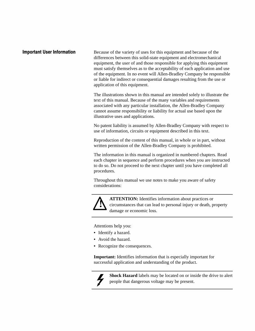
Summary of Manual Changes This release of the 1336VT-5.0 User Manual contains some new andupdated information. The new and updated information is summarized inthe table below. For further information, refer to the page numbersprovided.
Description of New or Updated Information Page Type
Unit Schematics – Figures 3.1, 3.2, 3.3, 3,4 3-2 – 3-9 Updated
General Installation Requirements Attention 5-1 New
General Wiring Procedures Attention 6-1 New
PreInstallation Care 11. . . . . . . . . . . . . . . . . . . . . . . . . . . . .
Receiving - Once you have received your drive, careful inspection for shipping damage must be made. Damage to the shipping carton is usually a good indication that it has received improper handling. Any and all damage should be immediately reported to the freight carrier and your nearest AllenBradley Area Sales/Support Center. 11. . . . . . . . . . . . . . . . . . . . . . . . . . . . . . . . . . . . . . . . .
Storage - If the drive will not immediately be installed, it should be stored in a clean, dry area where the ambient temperature is not less than 405C nor more than +855C. The drive must not be stored in a corrosive environment nor subject to conditions in excess of thestorage environment parameters stated in Chapter 4 Specifications. 11. . . . . . . . . . . . . . . . . . . . . . . . . . . . . . . . . . .
Handling - Depending upon the rating and options ordered, the weight of your drive can vary. To guard against injury to personnel,proper safety precautions and practices must be observed whenever the drive is being moved from one location to another. 11. . . . . . .
Shipping - The carton and materials that came with your drive have been designed and tested to provide reasonable protection againstdamage during transit. Should the drive be shipped to another location, it is recommended that the original shipping carton and packing material be used to protect the drive from damage in transit. 11. . .
Electrostatic Discharge - Electrostatic discharge generated by staticelectricity can damage the 12. . . . . . . . . . . . . . . . . . . . . . . . . . .
Precautions - Complimentary metallic oxide semiconductor devices on various drive boards. It is recommended that you perform theseprocedures to guard against this type of damage when circuit boards are removed or installed: 12. . . . . . . . . . . . . . . . . . . . . . . . . . . .
Overview 31. . . . . . . . . . . . . . . . . . . . . . . . . . . . . . . . . . . . . .
Wiring 61. . . . . . . . . . . . . . . . . . . . . . . . . . . . . . . . . . . . . . . .
Table of Contents
Preface
P-1
Manual Objective
This manual defines the installation, operation, startup and fault codes forthe Allen-Bradley 1336VT Adjustable Frequency AC Drive. It is intendedfor use by personnel familiar with the functions of solid-state driveequipment. Also provided are interconnection drawings for 1336 logicinterface options in Appendix A.
The 1336VT User Manual is designed to be read and used like an ordinarytextbook. Read the manual once from the beginning in the order presentedto gain basic knowledge about your drive. Each chapter builds uponinformation presented in the previous chapter.
To assure successful installation and operation, the material presented ineach chapter must be thoroughly read and understood before proceeding tothe next chapter. Particular attention should be directed to the Attention andImportant statements contained within. Become familiar with tasks thatmust be performed in a sequence for safety and successful completion.
Important: The Handheld Programming Terminal(Cat. No. 1336-MOD-E1) firmware must be upgraded with Kit SP-148340(Version 2.01) to be compatible with drive firmware Version 2.01 and 3.01.
The Monitor Display (Cat. No. 1336-MOD-E2) firmware must beupgraded with Kit SP-148341 (Version 2.01) to be compatible with drivefirmware Version 2.01 and 3.01.
Preface
P-2
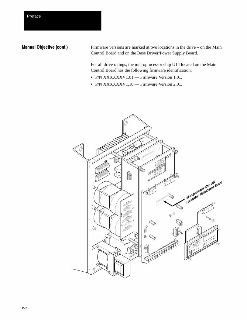
Manual Objective (cont.) Firmware versions are marked at two locations in the drive – on the MainControl Board and on the Base Driver/Power Supply Board.
For all drive ratings, the microprocessor chip U14 located on the MainControl Board has the following firmware identification:
• P/N XXXXXXV1.01 –– Firmware Version 1.01.
• P/N XXXXXXV1.10 –– Firmware Version 2.01.
Freq
PR
Enter
PR
StartJog
Stop
C1
C2➀
➁
SW1
GND GND
M1
+DC –DC
M3M2
L1L2
L3
HAZARDOUS VOLTAGE
ON
CAPACITORS WHEN
NEON
LIGHT IS ON. REMOVE POWER
AND WAIT 60 S
EC. BEFORE
S
ERVICING.
CAUTION
BULLETIN 1336VT ADJUSTABLE FREQUENCY AC DRIVE
12
43
56
78
9 10 11 12 13 14 15 16 17 18
Microprocessor Chip U14
Located on Main Control Board
CAUTION
HAZARDOUS VOLTAGE ON CAPACITORS
WHEN NEON LIGHT IS ON. REMOVE POWER
AND WAIT 60 SECONDS BEFORE SERVICING.
ATTENTION
TENSION DANGEREUSE AU NIVEAU DES
CONDENSATEURS QUAND LES NEONS SONT
ALLUMES. COUPER LE COURANT ET
ATTENDRE 60 SECONDES AVANT DE
COMMENCER L'ENTRETIEN.
VORSICHT
AN DEN KONDENSATOREN BESTEHT
HOCHSPANNUNGSGEFAHR, WENN DS NEON-
LICHT AUFLECUDHTET. STROM UNTER-
BRECHEN UND 60 SEK. WARTEN BEVOR
SERVICEARBEITEN DURCHGEFÜHRT WERDEN.
ATTENZIONE
TENSIONE PERICOLOSA SUI CONDENSATORI
QUANDO LA LUCE AL NEON È ACCESA.
TOGLIERE L'ALIMENTAZIONE ED ASPETTARE 60
SECONDI PRIMA DI PRESTARE MANUTENZIONE.
¿¬|– [¥
†[Ÿ Ÿº
|]º]
¬Ÿ[ ¿|]
Ÿº][, <|>/º
¥‡º
~|[º ¥
༠ټ][
<|>/º
¿Ÿº¿|]
|]º]
¬Ÿ[ ¿|]
ټ][, <
|>/º ¥‡º<|>/º
¥‡º
¬Ÿ[ ¿|]
PRECAUCION
AVOLTAJE PERLIGROSO EN LS CAPACITORES
CUANDO LA LUZ DE NEON ESTÉ ENCENDIO.
CORTE LA ENERGIA Y ESPERE 60 DEGUNDOS
ANTES DE DAR SERVICIO.
Preface
P-3
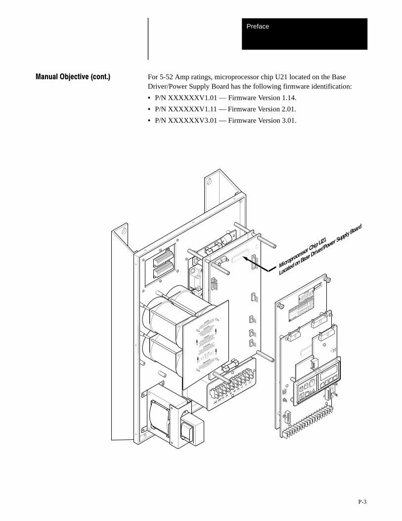
Manual Objective (cont.) For 5-52 Amp ratings, microprocessor chip U21 located on the BaseDriver/Power Supply Board has the following firmware identification:
• P/N XXXXXXV1.01 –– Firmware Version 1.14.
• P/N XXXXXXV1. 11 –– Firmware Version 2.01.
• P/N XXXXXXV3.01 –– Firmware Version 3.01.
HAZARDOUS VOLTAGE
ON
CAPACITORS WHEN
NEON
LIGHT IS ON. REMOVE POWER
AND WAIT 60 S
EC. BEFORE
S
ERVICING.
CAUTION
BULLETIN 1336VT ADJUSTABLE FREQUENCY AC DRIVE
GND GND
M1
+DC –DC
M3M2
L1L2
L3
12
43
56
78
9 10 11 12 13 14 15 16 17 18
Freq
PR
Enter
PR
StartJog
Stop
C1
C2➀
➁
SW1
Microprocessor Chip U21
Located on Base Driver/Power Supply Board
CAUTION
HAZARDOUS VOLTAGE ON CAPACITORS
WHEN NEON LIGHT IS ON. REMOVE POWER
AND WAIT 60 SECONDS BEFORE SERVICING.
ATTENTION
TENSION DANGEREUSE AU NIVEAU DES
CONDENSATEURS QUAND LES NEONS SONT
ALLUMES. COUPER LE COURANT ET
ATTENDRE 60 SECONDES AVANT DE
COMMENCER L'ENTRETIEN.
VORSICHT
AN DEN KONDENSATOREN BESTEHT
HOCHSPANNUNGSGEFAHR, WENN DS NEON-
LICHT AUFLECUDHTET. STROM UNTER-
BRECHEN UND 60 SEK. WARTEN BEVOR
SERVICEARBEITEN DURCHGEFÜHRT WERDEN.
ATTENZIONE
TENSIONE PERICOLOSA SUI CONDENSATORI
QUANDO LA LUCE AL NEON È ACCESA.
TOGLIERE L'ALIMENTAZIONE ED ASPETTARE 60
SECONDI PRIMA DI PRESTARE MANUTENZIONE.
¿¬|– [¥
†[Ÿ Ÿº
|]º]
¬Ÿ[ ¿|]
Ÿº][, <|>/º
¥‡º
~|[º ¥
༠ټ][
<|>/º
¿Ÿº¿|]
|]º]
¬Ÿ[ ¿|]
ټ][, <
|>/º ¥‡º<|>/º
¥‡º
¬Ÿ[ ¿|]
PRECAUCION
AVOLTAJE PERLIGROSO EN LS CAPACITORES
CUANDO LA LUZ DE NEON ESTÉ ENCENDIO.
CORTE LA ENERGIA Y ESPERE 60 DEGUNDOS
ANTES DE DAR SERVICIO.
Preface
P-4
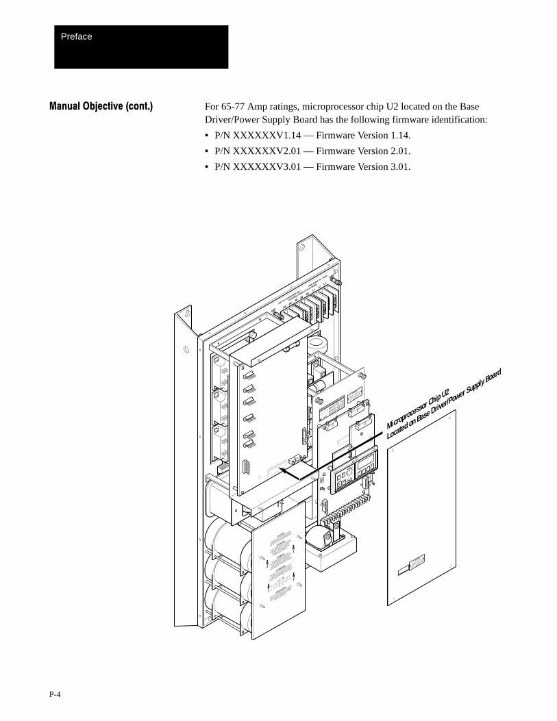
Manual Objective (cont.) For 65-77 Amp ratings, microprocessor chip U2 located on the BaseDriver/Power Supply Board has the following firmware identification:
• P/N XXXXXXV1.14 –– Firmware Version 1.14.
• P/N XXXXXXV2.01 –– Firmware Version 2.01.
• P/N XXXXXXV3.01 –– Firmware Version 3.01.
M–
+
HAZARDOUS VOLTAGE
ON
CAPACITORS WHEN
NEON
LIGHT IS ON. REMOVE POWER
AND WAIT 60 S
EC. BEFORE
S
ERVICING.
CAUTION
BULLETIN 1336VT ADJUSTABLE FREQUENCY AC DRIVE HAZARDOUS VOLTAGE
ON
CAPACITORS WHEN
NEON
LIGHT IS ON. REMOVE POWER
AND WAIT 60 S
EC. BEFORE
S
ERVICING.
CAUTION
12
43
56
78
9 10 11 12 13 14 15 16 17 18
Freq
PR
Enter
PR
StartJog
Stop
C1
C2➀
➁
SW1
CAUTION
HAZARDOUS VOLTAGE ON CAPACITORS
WHEN NEON LIGHT IS ON. REMOVE POWER
AND WAIT 60 SECONDS BEFORE SERVICING.
ATTENTION
TENSION DANGEREUSE AU NIVEAU DES
CONDENSATEURS QUAND LES NEONS SONT
ALLUMES. COUPER LE COURANT ET
ATTENDRE 60 SECONDES AVANT DE
COMMENCER L'ENTRETIEN.
VORSICHT
AN DEN KONDENSATOREN BESTEHT
HOCHSPANNUNGSGEFAHR, WENN DS NEON-
LICHT AUFLECUDHTET. STROM UNTER-
BRECHEN UND 60 SEK. WARTEN BEVOR
SERVICEARBEITEN DURCHGEFÜHRT WERDEN.
ATTENZIONE
TENSIONE PERICOLOSA SUI CONDENSATORI
QUANDO LA LUCE AL NEON È ACCESA.
TOGLIERE L'ALIMENTAZIONE ED ASPETTARE 60
SECONDI PRIMA DI PRESTARE MANUTENZIONE.
¿¬|– [¥
†[Ÿ Ÿº
|]º]
¬Ÿ[ ¿|]
Ÿº][, <|>/º
¥‡º
~|[º ¥
༠ټ][
<|>/º
¿Ÿº¿|]
|]º]
¬Ÿ[ ¿|]
ټ][, <
|>/º ¥‡º<|>/º
¥‡º
¬Ÿ[ ¿|]
PRECAUCION
AVOLTAJE PERLIGROSO EN LS CAPACITORES
CUANDO LA LUZ DE NEON ESTÉ ENCENDIO.
CORTE LA ENERGIA Y ESPERE 60 DEGUNDOS
ANTES DE DAR SERVICIO.
GND
GND
M1
+DC –DC
M3M2
L1L2
L3
USE 75°C COPPER WIRE ONLY
WIRE RANGE 2/0 – 6 AWG
TIGHTENING TORQE 120 INCH POUNDS
Microprocessor Chip U2
Located on Base Driver/Power Supply Board
Preface
P-5
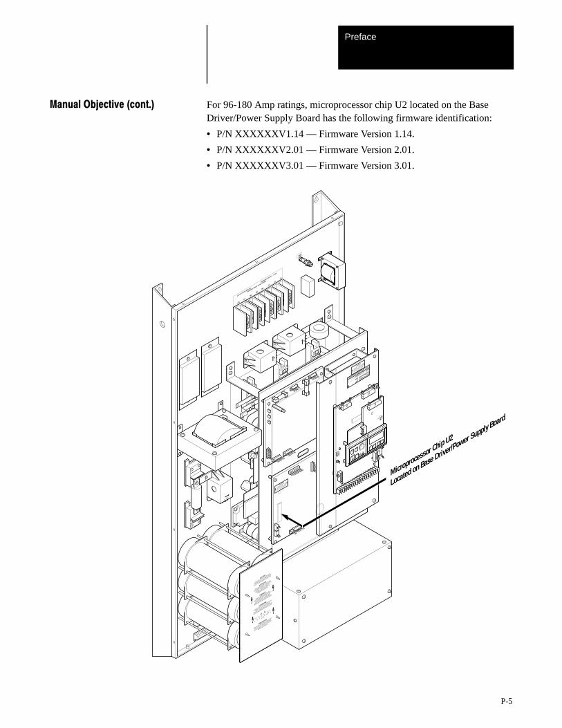
Manual Objective (cont.) For 96-180 Amp ratings, microprocessor chip U2 located on the BaseDriver/Power Supply Board has the following firmware identification:
• P/N XXXXXXV1.14 –– Firmware Version 1.14.
• P/N XXXXXXV2.01 –– Firmware Version 2.01.
• P/N XXXXXXV3.01 –– Firmware Version 3.01.
GND
+ DC
USE 75°C COPPER WIRE ONLY
WIRE RANGE 350 MCM –– 6 AWG
TIGHTENING TORQUE 275 INCH POUNDS
– DC
M1
M2M3
L1L2
L3
HAZARDOUS VOLTAGE
ON
CAPACITORS WHEN
NEON
LIGHT IS ON. REMOVE POWER
AND WAIT 60 S
EC. BEFORE
S
ERVICING.
CAUTION
M–
+
M–
+
M–
+
BULLETIN 1336VT ADJUSTABLE FREQUENCY AC DRIVE
HAZARDOUS VOLTAGE
ON
CAPACITORS WHEN
NEON
LIGHT IS ON. REMOVE POWER
AND WAIT 60 S
EC. BEFORE
S
ERVICING.
CAUTION
12
43
56
78
9 10 11 12 13 14 15 16 17 18
Freq
PR
Enter
PR
StartJog
Stop
C1
C2➀
➁
SW1
CAUTION
HAZARDOUS VOLTAGE ON CAPACITORS
WHEN NEON LIGHT IS ON. REMOVE POWER
AND WAIT 60 SECONDS BEFORE SERVICING.
ATTENTION
TENSION DANGEREUSE AU NIVEAU DES
CONDENSATEURS QUAND LES NEONS SONT
ALLUMES. COUPER LE COURANT ET
ATTENDRE 60 SECONDES AVANT DE
COMMENCER L'ENTRETIEN.
VORSICHT
AN DEN KONDENSATOREN BESTEHT
HOCHSPANNUNGSGEFAHR, WENN DS NEON-
LICHT AUFLECUDHTET. STROM UNTER-
BRECHEN UND 60 SEK. WARTEN BEVOR
SERVICEARBEITEN DURCHGEFÜHRT WERDEN.
ATTENZIONE
TENSIONE PERICOLOSA SUI CONDENSATORI
QUANDO LA LUCE AL NEON È ACCESA.
TOGLIERE L'ALIMENTAZIONE ED ASPETTARE 60
SECONDI PRIMA DI PRESTARE MANUTENZIONE.
¿¬|– [¥
†[Ÿ Ÿº
|]º]
¬Ÿ[ ¿|]
Ÿº][, <|>/º
¥‡º
~|[º ¥
༠ټ][
<|>/º
¿Ÿº¿|]
|]º]
¬Ÿ[ ¿|]
ټ][, <
|>/º ¥‡º<|>/º
¥‡º
¬Ÿ[ ¿|]
PRECAUCION
AVOLTAJE PERLIGROSO EN LS CAPACITORES
CUANDO LA LUZ DE NEON ESTÉ ENCENDIO.
CORTE LA ENERGIA Y ESPERE 60 DEGUNDOS
ANTES DE DAR SERVICIO.
Microprocessor Chip U2
Located on Base Driver/Power Supply Board
Preface
P-6
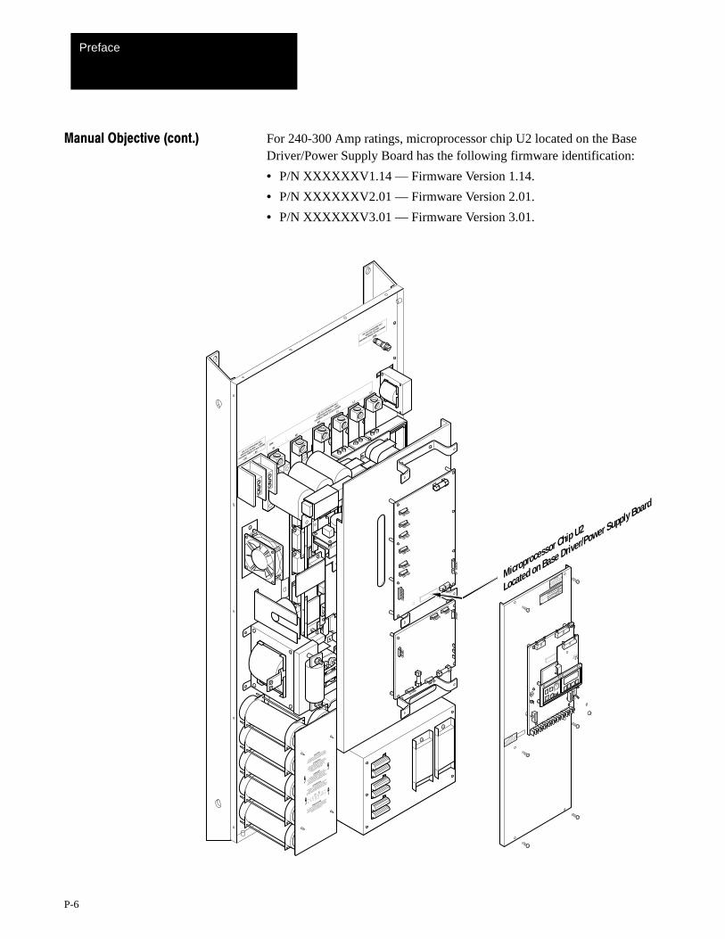
Manual Objective (cont.) For 240-300 Amp ratings, microprocessor chip U2 located on the BaseDriver/Power Supply Board has the following firmware identification:
• P/N XXXXXXV1.14 –– Firmware Version 1.14.
• P/N XXXXXXV2.01 –– Firmware Version 2.01.
• P/N XXXXXXV3.01 –– Firmware Version 3.01.
GND
M1
M3
M2
L1
L2
L3
USE 75°C COPPER WIRE ONLT.
WIRE RANGE 500 MCM –– 0 AWG
TIGHTENING TORQUE 375 INCH POUNDS
BULLETIN 1336VT ADJUSTABLE FREQUENCY AC DRIVEHAZARDOUS V
OLTAGE ON
CAPACITORS WHEN
NEON
LIGHT IS ON. REMOVE POWER
AND WAIT 60 S
EC. BEFORE
S
ERVICING.
CAUTION
HAZARDOUS VOLTAGE
ON
CAPACITORS WHEN
NEON
LIGHT IS ON. REMOVE POWER
AND WAIT 60 S
EC. BEFORE
S
ERVICING.
CAUTION
GNDUSE 75°C COPPER WIRE ONLY.
WIRE SIZE 2 (3) AWG
TIGHTENING TORQUE 275 INCH POUNDS
+ DC
– DCUSE 75°C COPPER WIRE ONLT.
WIRE RANGE 350 MCM –– 6 AWG
TIGHTENING TORQUE 275 INCH POUNDS
12
43
56
78
9 10 11 12 13 14 15 16 17 18
Freq
PR
Enter
PR
StartJog
Stop
C1
C2➀
➁
SW1
Microprocessor Chip U2
Located on Base Driver/Power Supply Board
CAUTION
HAZARDOUS VOLTAGE ON CAPACITORS
WHEN NEON LIGHT IS ON. REMOVE POWER
AND WAIT 60 SECONDS BEFORE SERVICING.
ATTENTION
TENSION DANGEREUSE AU NIVEAU DES
CONDENSATEURS QUAND LES NEONS SONT
ALLUMES. COUPER LE COURANT ET
ATTENDRE 60 SECONDES AVANT DE
COMMENCER L'ENTRETIEN.
VORSICHT
AN DEN KONDENSATOREN BESTEHT
HOCHSPANNUNGSGEFAHR, WENN DS NEON-
LICHT AUFLECUDHTET. STROM UNTER-
BRECHEN UND 60 SEK. WARTEN BEVOR
SERVICEARBEITEN DURCHGEFÜHRT WERDEN.
ATTENZIONE
TENSIONE PERICOLOSA SUI CONDENSATORI
QUANDO LA LUCE AL NEON È ACCESA.
TOGLIERE L'ALIMENTAZIONE ED ASPETTARE 60
SECONDI PRIMA DI PRESTARE MANUTENZIONE.
¿¬|– [¥
†[Ÿ Ÿº
|]º]
¬Ÿ[ ¿|]
Ÿº][, <|>/º
¥‡º
~|[º ¥
༠ټ][
<|>/º
¿Ÿº¿|]
|]º]
¬Ÿ[ ¿|]
ټ][, <
|>/º ¥‡º<|>/º
¥‡º
¬Ÿ[ ¿|]
PRECAUCION
AVOLTAJE PERLIGROSO EN LS CAPACITORES
CUANDO LA LUZ DE NEON ESTÉ ENCENDIO.
CORTE LA ENERGIA Y ESPERE 60 DEGUNDOS
ANTES DE DAR SERVICIO.
Preface
P-7
Manual Objective (cont.) This manual is meant to guide the user with interface, installation, setupand troubleshooting of a 1336VT. The contents are arranged in order froma general description to troubleshooting and maintenance. To assuresuccessful installation and operation, the material presented must bethoroughly read and understood before proceeding. Particular attentionmust be directed to the Caution, Warning and Important statementscontained within.
Important Information about this Manual
This manual has been prepared primarily to support this product in a singleapplication. It is a standard document that is intended to help the userunderstand the individual operating characteristics and limitations of thisequipment including hazards associated with installation and setupprocedures. Note the following points:
• This equipment has been designed to meet the requirements of acomponent in an integrated system.
• It must be noted that special considerations are to be given tocharacteristics of other peripheral solid-state control equipment and thecumulative impact on safety.
• Manufacturers and engineering groups responsible for specification ordesign of electrical control equipment must refer to applicable industrystandards and codes for specific safety guidelines and interfacerequirements.
• In the actual factory environment, the user is responsible to assurecompliance with applicable machine and operator safety codes orregulations which are beyond the scope and purpose of this document.
Preface
P-8
General Precautions In addition to the precautions listed throughout this manual, the followingstatements which are general to the system must be read and understood.
!ATTENTION: Only personnel familiar with the 1336VT ACDrive and associated machinery should plan or implement theinstallation, start-up and subsequent maintenance of the system.Failure to comply may result in personal injury and/or equipmentdamage.
!ATTENTION: An incorrectly applied or installed system canresult in component damage or reduction in product life. Wiring orapplication errors, such as undersizing the motor, incorrect orinadequate AC supply, or excessive ambient temperatures mayresult in malfunction of the system.
!ATTENTION: This assembly may contain parts andsub-assemblies that are sensitive to electrostatic discharge. Staticcontrol precautions are required when testing, servicing orrepairing this assembly. Component damage may result if youignore electrostatic discharge control procedures. If you are notfamiliar with static control procedures, reference Allen-BradleyPublication 8000-4.5.2, Guarding Against Electrostatic Damage orany other applicable ESD protection handbook.
1Chapter
1-1
PreInstallation Care
Before installing and operating your 1336VT, carefully read this manualand observe all precautions. The catalog number of your drive as explainedin Chapter 2 — Drive and Option Identification lists the drive rating, typeof enclosure, nominal line voltage, phase and frequency, as well as anyadditional options that you may have specified. Specifications for all drivesincluding standard controls, adjustment range, diagnostics andenvironmental qualifications are listed in Chapter 4 — Specifications.
Receiving Once you have received your drive, careful inspection for shipping damagemust be made. Damage to the shipping carton is usually a good indicationthat it has received improper handling. Any and all damage should beimmediately reported to the freight carrier and your nearest Allen-BradleyArea Sales/Support Center.
Carefully unpack the drive, taking care to save the shipping carton and anypacking material should return be necessary. Verify that the items on thepacking list or bill of lading agree with your order.
Storage If the drive will not immediately be installed, it should be stored in a clean,dry area where the ambient temperature is not less than -40°C nor morethan +85°C. The drive must not be stored in a corrosive environment norsubject to conditions in excess of the storage environment parametersstated in Chapter 4 — Specifications.
Handling Depending upon the rating and options ordered, the weight of your drivecan vary. To guard against injury to personnel, proper safety precautionsand practices must be observed whenever the drive is being moved fromone location to another.
Shipping The carton and materials that came with your drive have been designed andtested to provide reasonable protection against damage during transit.Should the drive be shipped to another location, it is recommended that theoriginal shipping carton and packing material be used to protect the drivefrom damage in transit.
Pre-Installation CareChapter 1
1-2
!ATTENTION: This assembly contains parts and sub-assembliesthat are sensitive to electrostatic discharge. Static controlprecautions are required when servicing this assembly. Componentdamage may result if you ignore electrostatic discharge controlprocedures. If you are not familiar with static control procedures,reference Allen-Bradley Publication 8000-4.5.2, Guarding AgainstElectrostatic Damage, or any other applicable ESD protectionhandbook.
Electrostatic Discharge Electrostatic discharge generated by static electricity can damage thePrecautions complimentary metallic oxide semiconductor devices on various drive
boards. It is recommended that you perform these procedures to guardagainst this type of damage when circuit boards are removed or installed:
• Wear a wrist type grounding strap that is grounded to the drive chassis.
• Attach the wrist strap before removing the new circuit board from theconductive packet.
• Remove boards from the drive and immediately insert them into theirconductive packets.
2Chapter
2-1
Drive and Option Identification
The following is an explanation of the catalog numbering system for1336VT Adjustable Frequency AC Drives and options. The catalognumber is coded to identify the drive power rating and can be found on thedrive shipping carton.
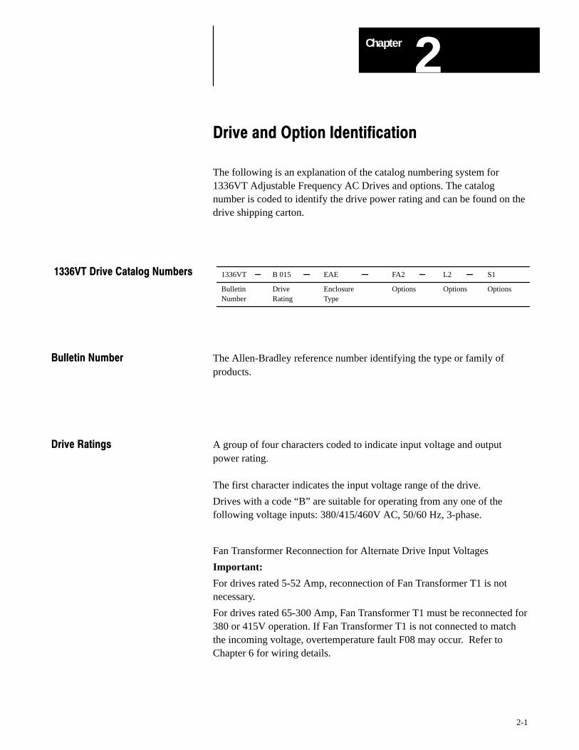
1336VT B 015 EAE FA2 L2 S1
Bulletin Drive Enclosure Options Options OptionsNumber Rating Type
1336VT Drive Catalog Numbers
Bulletin Number The Allen-Bradley reference number identifying the type or family ofproducts.
Drive Ratings A group of four characters coded to indicate input voltage and outputpower rating.
The first character indicates the input voltage range of the drive.
Drives with a code “B” are suitable for operating from any one of thefollowing voltage inputs: 380/415/460V AC, 50/60 Hz, 3-phase.
Fan Transformer Reconnection for Alternate Drive Input Voltages
Important:
For drives rated 5-52 Amp, reconnection of Fan Transformer T1 is notnecessary.
For drives rated 65-300 Amp, Fan Transformer T1 must be reconnected for380 or 415V operation. If Fan Transformer T1 is not connected to matchthe incoming voltage, overtemperature fault F08 may occur. Refer toChapter 6 for wiring details.
Drive and Option IdentificationChapter 2
2-2
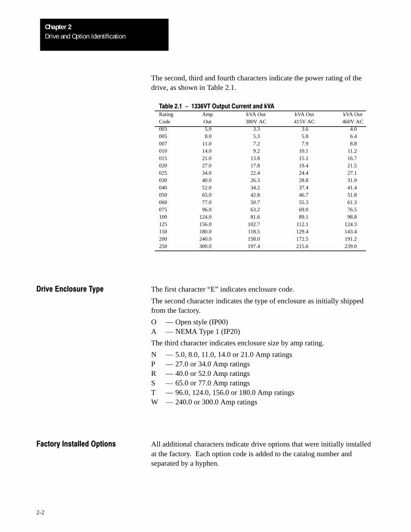
The second, third and fourth characters indicate the power rating of thedrive, as shown in Table 2.1.
Table 2.1 - 1336VT Output Current and kVARating Amp kVA Out kVA Out kVA OutCode Out 380V AC 415V AC 460V AC003 5.0 3.3 3.6 4.0005 8.0 5.3 5.8 6.4007 11.0 7.2 7.9 8.8010 14.0 9.2 10.1 11.2015 21.0 13.8 15.1 16.7020 27.0 17.8 19.4 21.5025 34.0 22.4 24.4 27.1030 40.0 26.3 28.8 31.9040 52.0 34.2 37.4 41.4050 65.0 42.8 46.7 51.8060 77.0 50.7 55.3 61.3075 96.0 63.2 69.0 76.5100 124.0 81.6 89.1 98.8125 156.0 102.7 112.1 124.3150 180.0 118.5 129.4 143.4200 240.0 158.0 172.5 191.2250 300.0 197.4 215.6 239.0
Drive Enclosure Type The first character “E” indicates enclosure code.
The second character indicates the type of enclosure as initially shippedfrom the factory.
O –– Open style (IP00)A –– NEMA Type 1 (IP20)
The third character indicates enclosure size by amp rating.
N –– 5.0, 8.0, 11.0, 14.0 or 21.0 Amp ratingsP –– 27.0 or 34.0 Amp ratingsR –– 40.0 or 52.0 Amp ratingsS –– 65.0 or 77.0 Amp ratingsT –– 96.0, 124.0, 156.0 or 180.0 Amp ratingsW –– 240.0 or 300.0 Amp ratings
Factory Installed Options All additional characters indicate drive options that were initially installedat the factory. Each option code is added to the catalog number andseparated by a hyphen.
3Chapter
3-1
Overview
The 1336VT is a microprocessor controlled, high performance, adjustablefrequency drive designed to control three phase induction motors oncritical industrial applications. The drive produces a three phase, PWM,adjustable frequency output to supply an adjustable motor speed. The driveoutput voltage is a function of output frequency and is adjustable to matchmotor parameters to obtain optimum motor performance.
To help achieve precise and repeatedly accurate control, setup andoperation, the 1336VT is digitally programmable. The drive may beprogrammed from a Local or Remote Control Panel or through the SerialCommunication Port using optional devices.
Depending upon your configuration, various status and fault conditions arereported either through the Programming and Display Panel or through theSerial Communications Port. All fault diagnostics start with both load anddrive self-check diagnostics each time the drive is powered up. Whilerunning, the drive continues to monitor potential fault conditions. To allowreal-time preventive maintenance, parameters such as drive output currentand control conditions can be monitored even while the drive is running.Should a fault occur, detailed diagnostic codes isolate the problem toidentify the condition, allowing quick, corrective action to be taken torestore process control.
OverviewChapter 3
3-2
1234567891011121314151617181920
1234567891011121314151617181920
123456789
1011121314151617181920
4 3 2 1
TB1
L1
L2
L3
GND
GND
1
2
3
BR1 –
+
MOV1
GNDSense
(AC)
1 2ST
L11 3
1 2
123456789101112131415161718
TB2
E1
192021222324252627282930
1234567891011121314151617181920
123456789
1011121314151617181920
J9 J2
J8
12345678910
123456789
10
123456789
10
123456789
10
12
GND
EARTHGROUND
CHASSISGROUND
SIGNALCOMMON
+ BUS
– BUS
Main Control Board(MAIN CTL)
J6 J1
J7
J4
Optional +5V DC TTLLogic Interface
orOptional 24V DC Logic
Interfaceor
Optional 115V AC LogicInterface
Programming andDisplay Board
(LOCAL DIS)
Optional LogicControl Board
(LOCAL CTL)
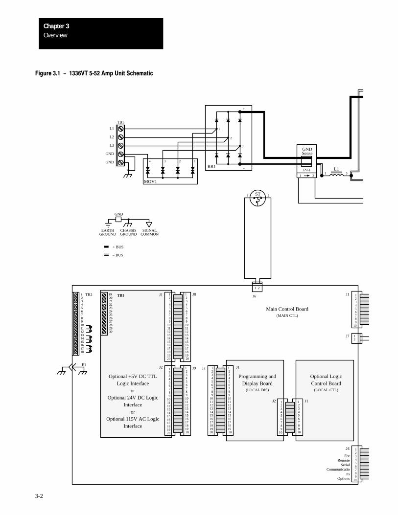
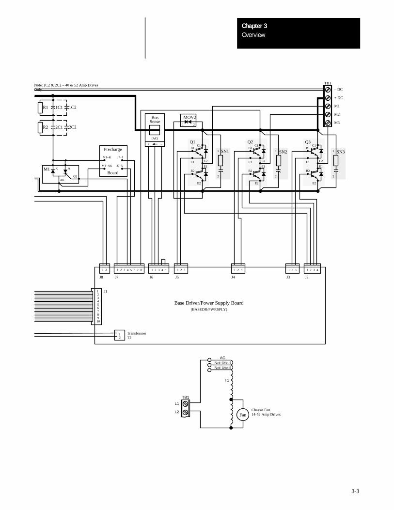
Figure 3.1 - 1336VT 552 Amp Unit Schematic
21
TB1 J1
J1
J1
J2
J2
ForRemote
SerialCommunicatio
nsOptions
123456789
1011121314151617181920
OverviewChapter 3
3-3
12345678910
12
J1
21 1 2 3 4 5 6 7 8 1 2 3 4 5 1 2 3 1 2 3 1 2 3 41 2 3
Base Driver/Power Supply Board(BASEDR/PWRSPLY)
J8 J7 J6 J5 J4 J3 J2
TB1
L1
L2Fan
T1
Not UsedAC
TB1
– DC
+ DC
M1
M2
M3
SN31
2
Q3B1
E2
C2
E1E1
B2
SN21
2
Q2B1
E2
C2
E1E1
B2
SN11
2
Q1B1
E2
C2
E1E1
B2
BusSense
(AC)
R1 1C1
R2 2C1
M1 K A
G2AK
Not Used
Precharge
Board
M1–K
M1–AK
J7–1
J7–5
+ –
Note: 1C2 & 2C2 – 40 & 52 Amp DrivesOnly
TransformerT2
C1 C1 C1
Chassis Fan14-52 Amp Drives
1C2
2C22
MOV2
1
OverviewChapter 3
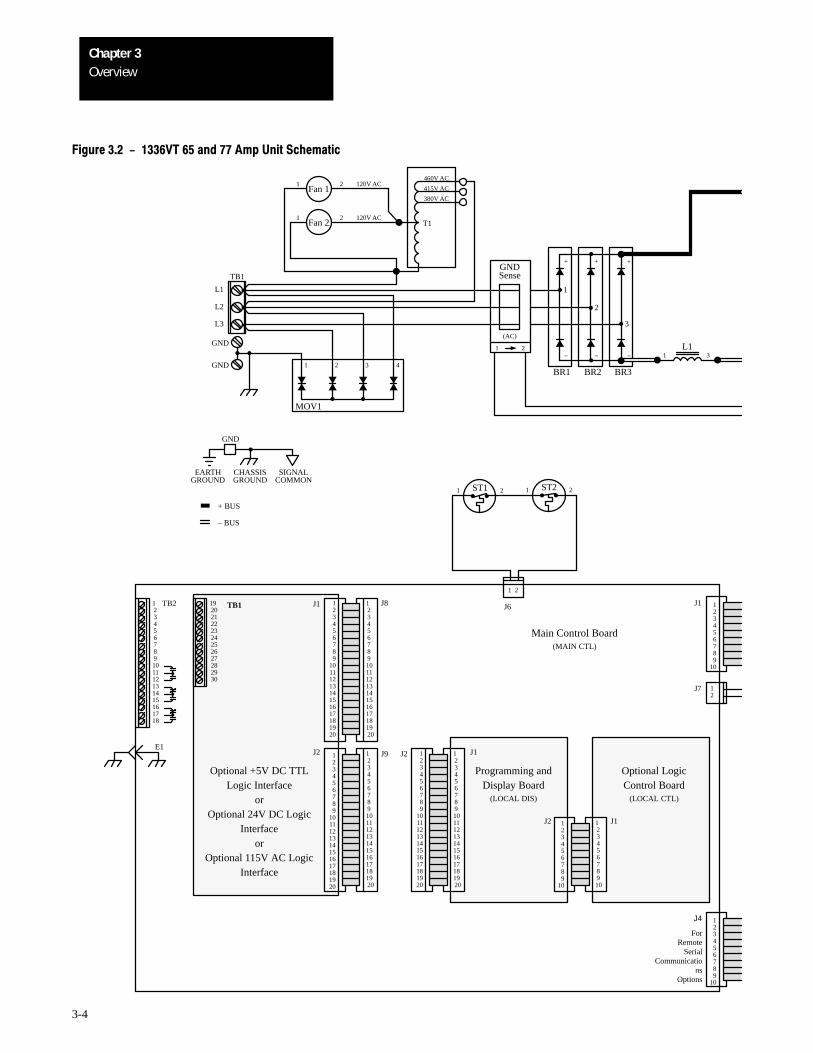
3-4
4321
TB1
L1
L2
L3
GND
GND
3
–
+
MOV1
GNDSense
(AC)
L11 3
Fan 1
T1
415V AC
380V AC
460V AC
1
2
–
+
–
+
BR1 BR2 BR3
1 2 120V AC
Fan 21 2 120V AC
21
Figure 3.2 - 1336VT 65 and 77 Amp Unit Schematic
1234567891011121314151617181920
1234567891011121314151617181920
123456789
1011121314151617181920
1 2ST1
1 2
123456789101112131415161718
TB2
E1
192021222324252627282930
1234567891011121314151617181920
123456789
1011121314151617181920
J9 J2
J8
12345678910
123456789
10
123456789
10
123456789
10
12
GND
EARTHGROUND
CHASSISGROUND
SIGNALCOMMON
+ BUS
– BUS
J6 J1
J7
J4
TB1 J1
J1
J1
J2
J2
123456789
1011121314151617181920
Main Control Board(MAIN CTL)
Optional +5V DC TTLLogic Interface
orOptional 24V DC Logic
Interfaceor
Optional 115V AC LogicInterface
Programming andDisplay Board
(LOCAL DIS)
Optional LogicControl Board
(LOCAL CTL)
ForRemote
SerialCommunicatio
nsOptions
1 2ST2
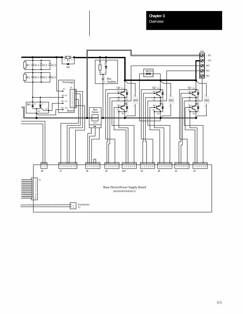
OverviewChapter 3
3-5
C1
1
J3
123456789
10
J1
21 1 2 3 4 5 6 7 8
J8 J7
TB1
– DC
+ DC
M3
M2
M1
Q1B1
C1
E2
C2
E1
E1
B2
Q2B1
E2
C2
E1
E1
B2
Q3B1
C1
E2
C2
E1
E1
B2
BusSense
(AC)
R1
R2
M1 K A
G2AK
Precharge
Board
M1–G1
M1–AK
+ –
1 2 3 4 5 6
J6
1 2 3 4 5 6
J5
1 2 3 4 5 6
J10
1 2 3 4 5 6
J4
1 2 3 4 5 6
J9
2 3 4 5 6 1 2 3 4 5 6
J2
SN1
1
2
12345678
J1
1
2
2
1
2
1
B+
M1–K
BusSnubber
1C1 1C2 1C3
2C1 2C2 2C3
E2E2E2
SN2
1
2
SN3
1
2
12
TransformerT2
Base Driver/Power Supply Board(BASEDR/PWRSPLY)
D2
F11 2
2
MOV2
1
OverviewChapter 3
3-6
1234567891011121314151617181920
123456789
1011121314151617181920
1234567891011121314151617181920
123456789
1011121314151617181920
1234567891011121314151617181920
123456789
1011121314151617181920
TB3
123456
1234
4321
TB1
L1
L2
L3
GNDG2
G1
MOV1
(AC)
1 2ST1
1 2
123456789101112131415161718
TB2
E1
192021222324252627282930
J9 J2
J8
12345678910
123456789
10
123456789
10
123456789
10
GND
EARTHGROUND
CHASSISGROUND
SIGNALCOMMON
+ BUS
– BUS
J6 J1
J7
J4
Fan
T1
415V AC
380V AC
460V AC
BR1 BR2 BR3
21
120V AC
1
2
TB4
123456789
10
12345
K2
G2
G1
K2
G2
G1
K2
SN7
R4
E3
R5E1
E4
E2 12345678
12345
J5
J6
J7
J8
J1
J2
L11 2
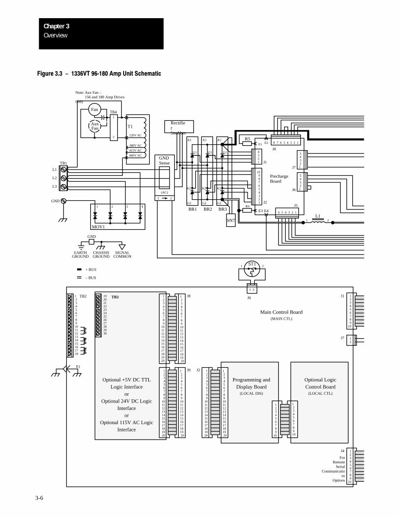
Figure 3.3 - 1336VT 96180 Amp Unit Schematic
12
K1K1K1
PrechargeBoard
RectifierSnubber
GNDSense
Main Control Board(MAIN CTL)
Optional +5V DC TTLLogic Interface
orOptional 24V DC Logic
Interfaceor
Optional 115V AC LogicInterface
Programming andDisplay Board
(LOCAL DIS)
Optional LogicControl Board
(LOCAL CTL)
ForRemote
SerialCommunicatio
nsOptions
AuxFan
Note: Aux Fan –156 and 180 Amp Drives
Only
OverviewChapter 3
3-7
C (X2, X4, X6)
E (– BUS)
+ BUS
– BUS
E (X1, X3, X5)
C (+ BUS)
SN2, SN4 & SN6 SN1, SN3 & SN5
SnubberDiagrams
12345678910
J1
21 1 2 3 4 5 6 7 8
J8 J7
TB1
– DC
+ DC
M1
M2
M3
1 2 3 4 5 6
J6
1 2 3 4 5 6
J5
1 2 3 4 5 6
J10
1 2 3 4 5 6
J4
1 2 3 4 5 6
J9
1 2 3 4 5 6
J3
1 2 3 4 5 6
J2
BSN5X5
C
E
BSN6X6
C
E
+–
LEM C
BSN3X3
C
E
BSN4X4
C
E
BSN1X1
C
E
BSN2X2
C
E
+–
LEM A
D1
F11 2
X1–6
C
BB
BX
E
C
B
BX
C
B
BX
X1–6
B
E E
C
E
Output TransistorDiagrams
12
TransformerT2
Base Driver/Power Supply Board(BASEDR/PWRSPLY)
96 and 124 Amp 156 and 180 Amp
(AC)
+ –
BUSSense
R1
R2
1C1 1C2 1C3
2C1 2C2 2C3
1C4-6C4 1C4-6C4
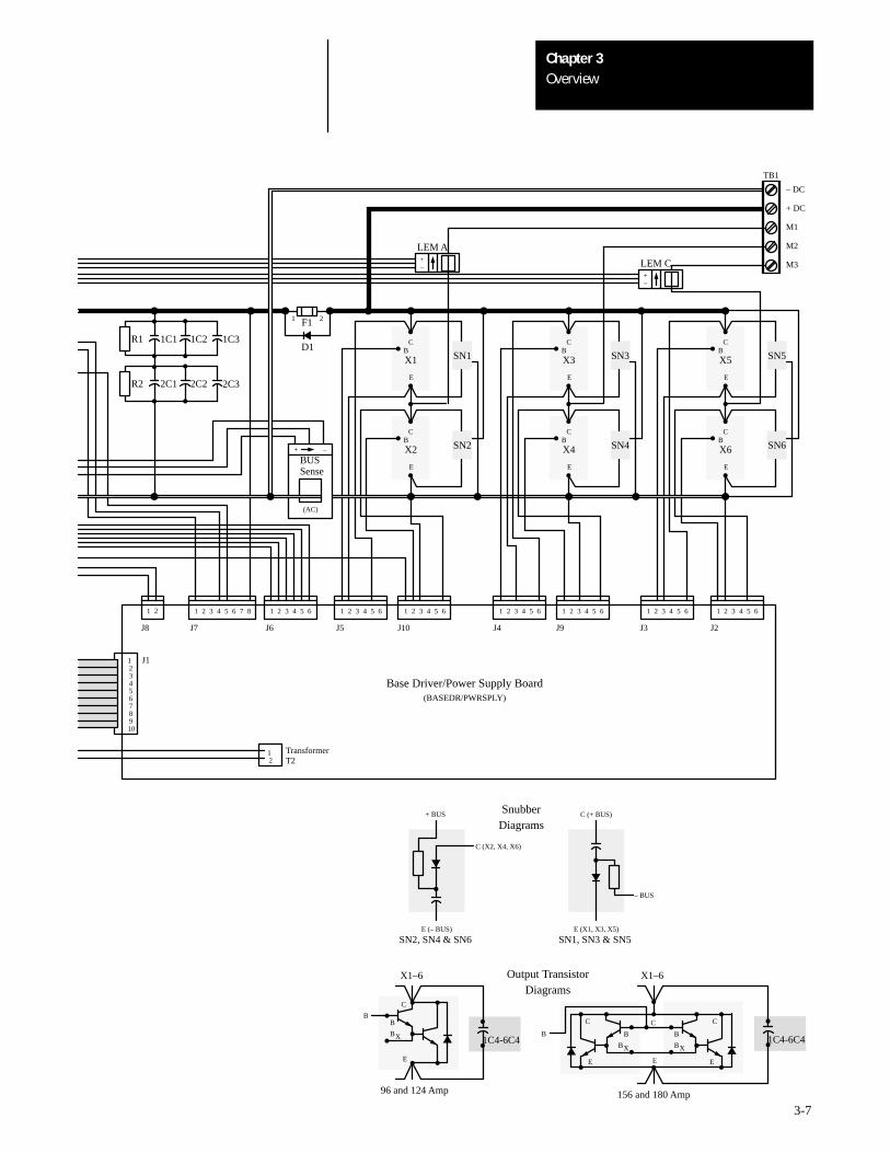
OverviewChapter 3
3-8
1234567891011121314151617181920
123456789
1011121314151617181920
1234567891011121314151617181920
123456789
1011121314151617181920
1234567891011121314151617181920
123456789
1011121314151617181920
TB3
K1K1K1
123456
1234
4321
TB1
L1
L2
L3
G2
G1
MOV1
(AC)
1 2ST1
1 2
123456789101112131415161718
TB2
E1
192021222324252627282930
J9 J2
J8
12345678910
123456789
10
123456789
10
123456789
10
J6 J1
J7
J4
Fan 1
T1
415V AC
380V AC
460V AC
BR1 BR2 BR3
21
120V AC
1
2
TB4
12345678910
12345
K2
G2
G1
K2
G2
G1
K2
SN7
R8E3
R7E1
E4
E2 12345678
12345
J5
J6
J7
J8
J1
J2
L11 2
Fan 2
SN8
SN9 SN10
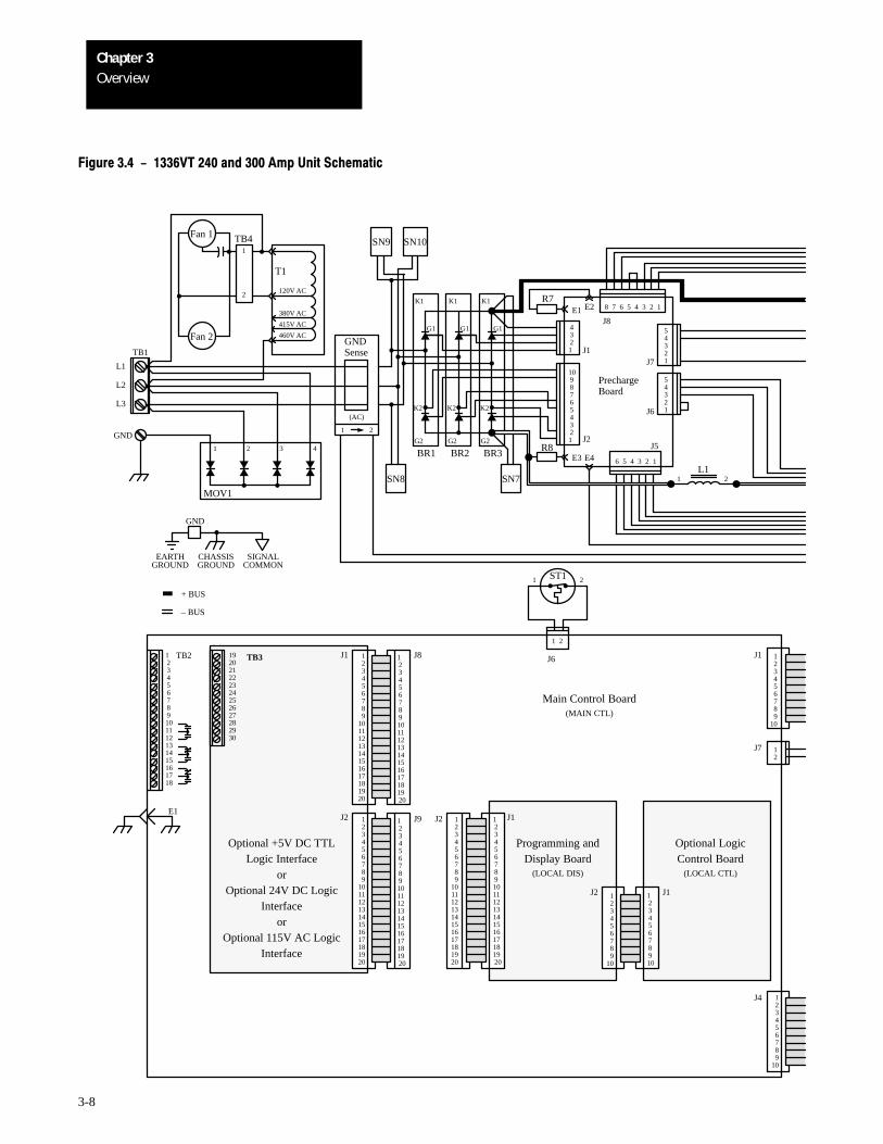
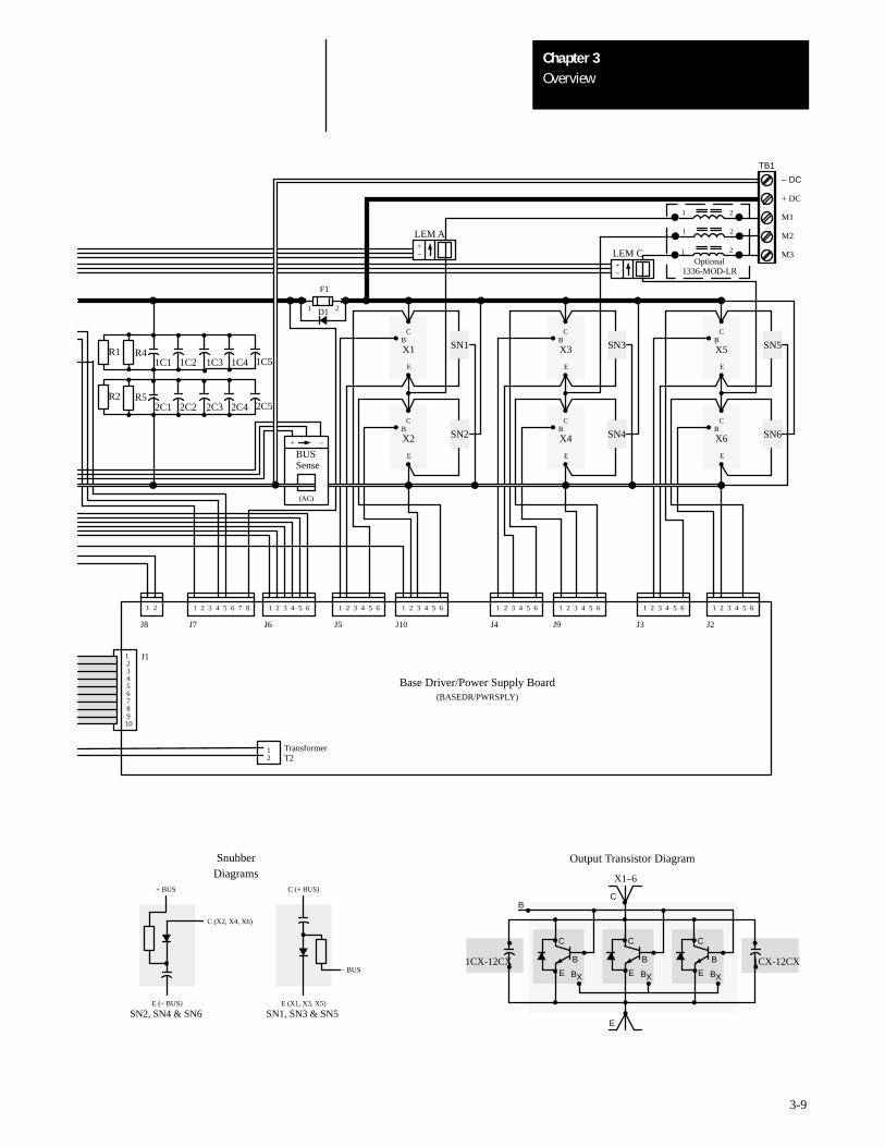
Figure 3.4 - 1336VT 240 and 300 Amp Unit Schematic
12
GND
EARTHGROUND
CHASSISGROUND
SIGNALCOMMON
+ BUS
– BUS
J2
J2 J1
J1
J1
Optional +5V DC TTLLogic Interface
orOptional 24V DC Logic
Interfaceor
Optional 115V AC LogicInterface
Programming andDisplay Board
(LOCAL DIS)
Optional LogicControl Board
(LOCAL CTL)
Main Control Board(MAIN CTL)
PrechargeBoard
GNDSense
GND
OverviewChapter 3
3-9
1CX-12CX1CX-12CX
12345678910
J1
21 1 2 3 4 5 6 7 8
J8 J7
TB1
– DC
+ DC
M1
M2
M3
1 2 3 4 5 6
J6
1 2 3 4 5 6
J5
1 2 3 4 5 6
J10
1 2 3 4 5 6
J4
1 2 3 4 5 6
J9
1 2 3 4 5 6
J3
1 2 3 4 5 6
J2
BSN5X5
C
E
BSN6X6
C
E
+–
LEM C
BSN3X3
C
E
BSN4X4
C
E
BSN1X1
C
E
BSN2X2
C
E
+–
LEM A
R4
R5
1C1 1C2 1C3
2C1 2C2 2C3
Optional
R1
R2
1C4 1C5
2C4 2C5
12
TransformerT2
Base Driver/Power Supply Board(BASEDR/PWRSPLY)
1 2
2
1 2
1
1336-MOD-LR
D11 2
(AC)
+ –
BUSSense
F1
C
B
BX
X1–6
E
B
E
C
C
B
BXE
C
B
BXE
Output Transistor Diagram
C (X2, X4, X6)
E (– BUS)
+ BUS
– BUS
E (X1, X3, X5)
C (+ BUS)
SN2, SN4 & SN6 SN1, SN3 & SN5
SnubberDiagrams
OverviewChapter 3
3-10
The 1336VT is an AC adjustable frequency drive designed for use with astandard, three-phase induction motor. The standard control is designed asa constant torque, adjustable speed control with 115% overload capabilityand is adaptable through programming to handle a wide variety ofapplications.
The 1336VT provides an exceptional output voltage and current waveform.Special considerations however, must be taken when applying an inverterto an existing motor.
The 1336VT provides a three-phase motor with variable frequency andvoltage utilizing PWM (Pulse Width Modulated) technology. Varying thefrequency of the applied power to the motor varies the speed of the motor.
The 1336VT is designed for use with variable torque, square law andcubed law loads. With square law loads, the torque varies directly with thechange in speed while the horsepower varies as the square of the speedchange. With cubed law loads, the torque varies as the square of the speedchange while the horsepower varies as the cube of the speed change.
Typical examples of square law loads are:
• Some positive displacement pumps.
• Some extruders and some mixers.
Typical examples of cube law loads are:
• Some centrifugal pumps.
• Fans and blowers.
Regardless of whether your application is a square law or cube law load,sizing of the 1336VT should be based upon the motor load current requiredat maximum operating speed. Caution is advised in going above motorbase (nameplate) speed in these applications.
OverviewChapter 3
3-11
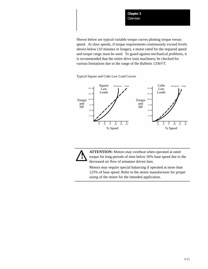
Shown below are typical variable torque curves plotting torque versusspeed. At slow speeds, if torque requirements continuously exceed levelsshown below (10 minutes or longer), a motor rated for the required speedand torque range must be used. To guard against mechanical problems, itis recommended that the entire drive train machinery be checked forvarious limitations due to the range of the Bulletin 1336VT.
Typical Square and Cube Law Load Curves
TorqueandHP
25
50
75
100
125
150
25 50 75 100 125 150
TorqueHorsepowerSquareLaw
Loads
% Speed
TorqueandHP
25
50
75
100
125
150
25 50 75 100 125 150
TorqueHorsepowerCubeLaw
Loads
% Speed
!ATTENTION: Motors may overheat when operated at ratedtorque for long periods of time below 50% base speed due to thedecreased air flow of armature driven fans.
Motors may require special balancing if operated at more than125% of base speed. Refer to the motor manufacturer for propersizing of the motor for the intended application.
4Chapter
4-1
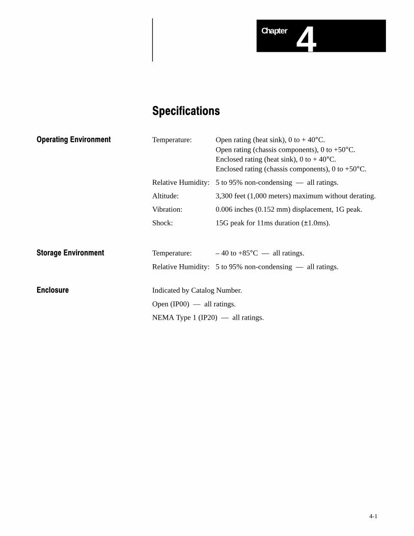
Specifications
Operating Environment Temperature: Open rating (heat sink), 0 to + 40°C.Open rating (chassis components), 0 to +50°C.Enclosed rating (heat sink), 0 to + 40°C.Enclosed rating (chassis components), 0 to +50°C.
Relative Humidity: 5 to 95% non-condensing –– all ratings.
Altitude: 3,300 feet (1,000 meters) maximum without derating.
Vibration: 0.006 inches (0.152 mm) displacement, 1G peak.
Shock: 15G peak for 11ms duration (±1.0ms).
Storage Environment Temperature: – 40 to +85°C –– all ratings.
Relative Humidity: 5 to 95% non-condensing –– all ratings.
Enclosure Indicated by Catalog Number.
Open (IP00) –– all ratings.
NEMA Type 1 (IP20) –– all ratings.
SpecificationsChapter 4
4-2
Input Power Conditioning General
Typically the 1336VT is suitable for direct connection to a correct voltage,three phase, AC power line. There are however certain power lineconditions which may introduce the possibility of drive input powercomponent malfunction. To reduce the possibility of these malfunctions, aline reactor or isolation type transformer may be required.
The basic rules for determining if a line reactor or isolation typetransformer is required are as follows:
1. If the AC line supplying the drive has power factor correction capacitorsconnected, an AC line reactor or isolation type transformer must beconnected between the capacitor bank and the input to the drive.
2. If the AC line frequently experiences transient power interruptions orsignificant voltage spikes, an AC line reactor or isolation typetransformer should be used.
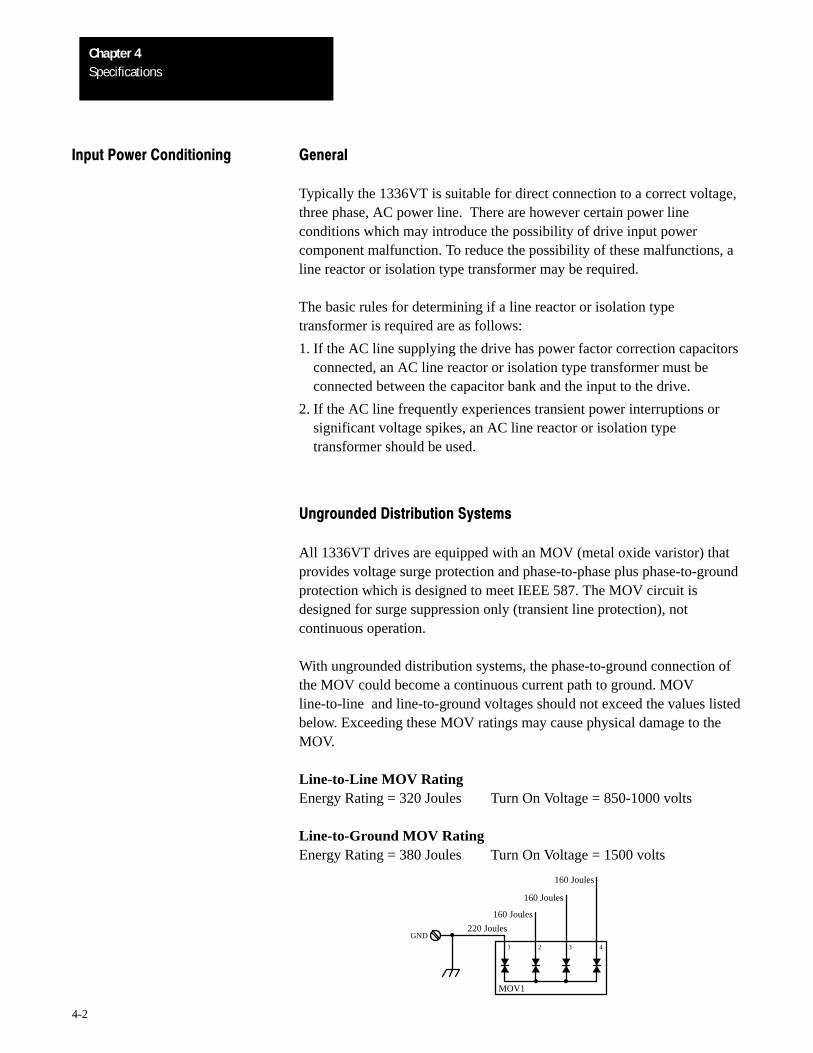
Ungrounded Distribution Systems
All 1336VT drives are equipped with an MOV (metal oxide varistor) thatprovides voltage surge protection and phase-to-phase plus phase-to-groundprotection which is designed to meet IEEE 587. The MOV circuit isdesigned for surge suppression only (transient line protection), notcontinuous operation.
With ungrounded distribution systems, the phase-to-ground connection ofthe MOV could become a continuous current path to ground. MOVline-to-line and line-to-ground voltages should not exceed the values listedbelow. Exceeding these MOV ratings may cause physical damage to theMOV.
Line-to-Line MOV RatingEnergy Rating = 320 Joules Turn On Voltage = 850-1000 volts
Line-to-Ground MOV RatingEnergy Rating = 380 Joules Turn On Voltage = 1500 volts
4321
GND
MOV1
220 Joules
160 Joules
160 Joules
160 Joules
SpecificationsChapter 4
4-3
Input Power Voltage: 380-460V AC ±10%.
Frequency: 48 to 62Hz.
Phase: 3-phase.
AC Input Overvoltage Trip: 570V AC.
AC Input Undervoltage Trip: 275V AC.
Bus Overvoltage Trip: 810V DC
Bus Undervoltage Trip: 388V DC
Line Transient Protection: Line transients up to 5,000 volts peak, 320 Joules.
Logic Power Ride-Thru: 2 seconds or longer –– subject to theintegrity of user supplied external circuits.
Control Logic Noise: Showering arc transients from 350 to 2,000Immunity volts peak.
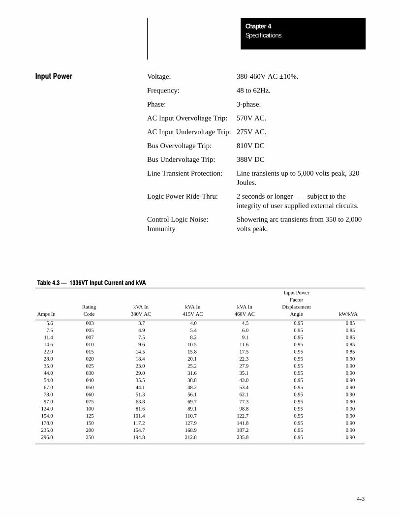
Table 4.3 1336VT Input Current and kVA
Input PowerFactor
Rating kVA In kVA In kVA In DisplacementAmps In Code 380V AC 415V AC 460V AC Angle kW/kVA
5.6 003 3.7 4.0 4.5 0.95 0.857.5 005 4.9 5.4 6.0 0.95 0.85
11.4 007 7.5 8.2 9.1 0.95 0.8514.6 010 9.6 10.5 11.6 0.95 0.8522.0 015 14.5 15.8 17.5 0.95 0.8528.0 020 18.4 20.1 22.3 0.95 0.9035.0 025 23.0 25.2 27.9 0.95 0.9044.0 030 29.0 31.6 35.1 0.95 0.9054.0 040 35.5 38.8 43.0 0.95 0.9067.0 050 44.1 48.2 53.4 0.95 0.9078.0 060 51.3 56.1 62.1 0.95 0.9097.0 075 63.8 69.7 77.3 0.95 0.90
124.0 100 81.6 89.1 98.8 0.95 0.90154.0 125 101.4 110.7 122.7 0.95 0.90178.0 150 117.2 127.9 141.8 0.95 0.90235.0 200 154.7 168.9 187.2 0.95 0.90296.0 250 194.8 212.8 235.8 0.95 0.90
SpecificationsChapter 4
4-4
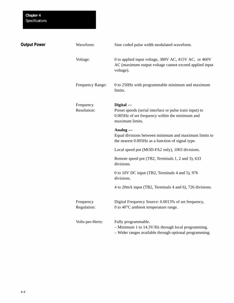
Output Power Waveform: Sine coded pulse width modulated waveform.
Voltage: 0 to applied input voltage, 380V AC, 415V AC, or 460VAC (maximum output voltage cannot exceed applied inputvoltage).
Frequency Range: 0 to 250Hz with programmable minimum and maximumlimits.
Frequency Digital —Resolution: Preset speeds (serial interface or pulse train input) to
0.005Hz of set frequency within the minimum andmaximum limits.
Analog —Equal divisions between minimum and maximum limits tothe nearest 0.005Hz as a function of signal type.
Local speed pot (MOD-FA2 only), 1003 divisions.
Remote speed pot (TB2, Terminals 1, 2 and 3), 633divisions.
0 to 10V DC input (TB2, Terminals 4 and 5), 976divisions.
4 to 20mA input (TB2, Terminals 4 and 6), 726 divisions.
Frequency Digital Frequency Source: 0.0013% of set frequency,Regulation: 0 to 40°C ambient temperature range.
Volts-per-Hertz: Fully programmable.– Minimum 1 to 14.3V/Hz through local programming.– Wider ranges available through optional programming.
SpecificationsChapter 4
4-5
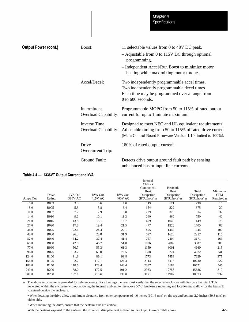
Output Power (cont.) Boost: 11 selectable values from 0 to 48V DC peak.
– Adjustable from 0 to 115V DC through optional programming.
– Independent Accel/Run Boost to minimize motor heating while maximixing motor torque.
Accel/Decel: Two independently programmable accel times.Two independently programmable decel times.Each time may be programmed over a range from0 to 600 seconds.
Intermittent Programmable MOPC from 50 to 115% of rated outputOverload Capability: current for up to 1 minute maximum.
Inverse Time Designed to meet NEC and UL equivalent requirements.Overload Capability: Adjustable timing from 50 to 115% of rated drive current
(Main Control Board Firmware Version 1.10 limited to 100%).
Drive 180% of rated output current.Overcurrent Trip:
Ground Fault: Detects drive output ground fault path by sensingunbalanced bus or input line currents.
Table 4.4 1336VT Output Current and kVA
InternalChassis
Component HeatsinkHeat Heat Total Minimum
Drive kVA Out kVA Out kVA Out Dissipation Dissipation Dissipation CFMAmps Out Rating 380V AC 415V AC 460V AC (BTU/hour) n (BTU/hour) n (BTU/hour) n Required n
5.0 B003 3.3 3.6 4.0 119 171 290 158.0 B005 5.3 5.8 6.4 154 222 375 20
11.0 B007 7.2 7.9 8.8 239 375 614 3214.0 B010 9.2 10.1 11.2 290 460 750 4021.0 B015 13.8 15.1 16.7 409 1040 1449 7527.0 B020 17.8 19.4 21.5 477 1228 1705 8834.0 B025 22.4 24.4 27.1 495 1449 1944 10040.0 B030 26.3 28.8 31.9 597 1620 2217 11552.0 B040 34.2 37.4 41.4 767 2404 3171 16565.0 B050 42.8 46.7 51.8 1006 2882 3887 20077.0 B060 50.7 55.3 61.3 1159 3001 4160 21596.0 B075 63.2 69.0 76.5 1398 3274 4672 241
124.0 B100 81.6 89.1 98.8 1773 5456 7229 375156.0 B125 102.7 112.1 124.3 2114 8116 10230 527180.0 B150 118.5 129.4 143.4 2387 8184 10571 545240.0 B200 158.0 172.5 191.2 2933 12753 15686 810300.0 B250 197.4 215.6 239.0 3171 14902 18073 932
n The above information is provided for reference only. For all ratings the user must verify that the selected enclosure will dissipate the total BTUsgenerated within the enclosure without allowing the internal ambient to rise above 50°C. Enclosure mounting and location must allow for the heatsinkto extend outside the enclosure.
• When locating the drive allow a minimum clearance from other components of 4.0 inches (101.6 mm) on the top and bottom, 2.0 inches (50.8 mm) oneither side.
• When mounting the drive, ensure that the heatsink fins are vertical.
With the heatsink exposed to the ambient, the drive will dissipate heat as listed in the Output Current Table above.
SpecificationsChapter 4
4-6
Required Control Inputs As a minimum requirement for drive operation, the following five controlinputs must be present to operate the drive:
Start
A momentary True input will start the drive. The drive will continue to rununtil a stop input is issued or a drive fault occurs. A start input may comefrom:
• The optional FA2, RP2 or RP3 control panel start pushbutton.
• A user supplied N.O. contact or start pushbutton connected to theoptional L1, L2, or L3 Logic Interface Board. Refer to Appendix A —Logic Interface Options and the 1336-MOD-L1, L2, or L3 instructionmanual.
• A user supplied start signal sent to the optional G2 Remote I/O InterfaceBoard. Refer to the 1336-MOD-G2 instruction manual.
Stop
A momentary False input will stop the drive. A maintained True input willpermit the drive to run or jog. A stop input may come from:
• The optional FA2, RP2 or RP3 control panel stop pushbutton.
• A user supplied maintained contact or Stop pushbutton connected to theoptional L1, L2, or L3 Logic Interface Board. Refer to Appendix A —Logic Interface Options and the 1336-MOD-L1, L2, or L3 instructionmanual.
• A user supplied stop signal sent to the optional G2 Remote I/O InterfaceBoard. Refer to the 1336-MOD-G2 instruction manual.
• The Main Control Board when Jumper J8 is installed between Pins 11and 12. Refer to Chapter 6 — Wiring, page 6-16.
Enable
A maintained True input or a maintained closed contact will permit thedrive to start, run, or jog. A momentary False input or an open contact willdisable drive output. An enable input may come from:
• A user supplied maintained contact or switch connected to the optionalL1, L2 or L3 Logic Interface Board. Refer to Appendix A — LogicInterface Options and the 1336-MOD-L1, L2 or L3 instruction manual.
• The Main Control Board when Jumper J9 is installed between Pins 7 and8. Refer to Chapter 6 — Wiring, page 6-16.
SpecificationsChapter 4
4-7
Required Control Inputs (cont.) Speed Reference
Speed reference sets the drive operating frequency. A speed reference inputmay come from:
• A Control Panel speed potentiometer.
• A user supplied 10kΩ remote speed potentiometer connected to terminalblock TB2. Refer to Chapter 6 — Wiring.
• A 4-20mA analog signal connected to terminal block TB2. Refer to Chapter 6 — Wiring.
• A 0-10V DC analog signal connected to terminal block TB2. Refer to Chapter 6 — Wiring.
• A pulse train input signal connected to terminal block TB2. Refer to Chapter 6 — Wiring.
• One of seven preset speed signals connected to the optional L1, L2, orL3 Logic Interface Board, or the optional G2 Remote I/O InterfaceBoard. Refer to Appendix A — Logic Interface Options and the1336-MOD-L1, L2 or L3 instruction manual or the 1336-MOD-G2instruction manual.
Auxiliary
A maintained True input or a maintained closed contact will permit thedrive to start, run, or jog. A momentary False input or an open contact willdisable drive output and generate Fault F02. An auxiliary input may comefrom:
• A user supplied maintained contact or switch connected to the optionalL1, L2 or L3 Logic Interface Board. Refer to Appendix A — LogicInterface Options and the 1336-MOD-L1, L2, or L3 instruction manual.
• The Main Control Board when Jumper J9 is installed between Pins 9 and10. Refer to Chapter 6 — Wiring, page 6-16.
SpecificationsChapter 4
4-8
Optional Control Inputs Reverse
Reverse changes direction of motor rotation. Reverse inputs may comefrom:
• A Control Panel direction pushbutton.
• The optional L1, L2 or L3 Logic Interface Board. Refer to Appendix A— Logic Interface Options and the 1336-MOD-L1, L2 or L3 instructionmanual.
• The optional G2 Remote I/O Interface Board. Refer to the1336-MOD-G2 instruction manual.
Jog
Jog jogs the drive at a pre-programmed jog speed. Jog inputs may comefrom:
• A Control Panel jog pushbutton.
• The optional L1, L2 or L3 Logic Interface Board. Refer to Appendix A— Logic Interface Options and the 1336-MOD-L1, L2 or L3 instructionmanual.
• The optional G2 Remote I/O Interface Board. Refer to the1336-MOD-G2 instruction manual.
Speed Select
Speed select permits switching between two selected speed referencesources. Speed select inputs may come from:
• The optional L1, L2 or L3 Logic Interface Board. Refer to Appendix A— Logic Interface Options and the 1336-MOD-L1, L2 or L3 instructionmanual.
• The optional G2 Remote I/O Interface Board. Refer to the1336-MOD-G2 instruction manual.
2nd Accel/Decel
2nd accel/decel permits switching between two internally programmedaccel/decel rates. 2nd accel/decel inputs may come from:
• The optional L1, L2 or L3 Logic Interface Board. Refer to Appendix A— Logic Interface Options and the 1336-MOD-L1, L2 or L3 instructionmanual.
• The optional G2 Remote I/O Interface Board. Refer to the1336-MOD-G2 instruction manual.
SpecificationsChapter 4
4-9
Load Requirements A balanced 3-phase inductive motor load is typical. Other motor loads mayrequire application assistance.
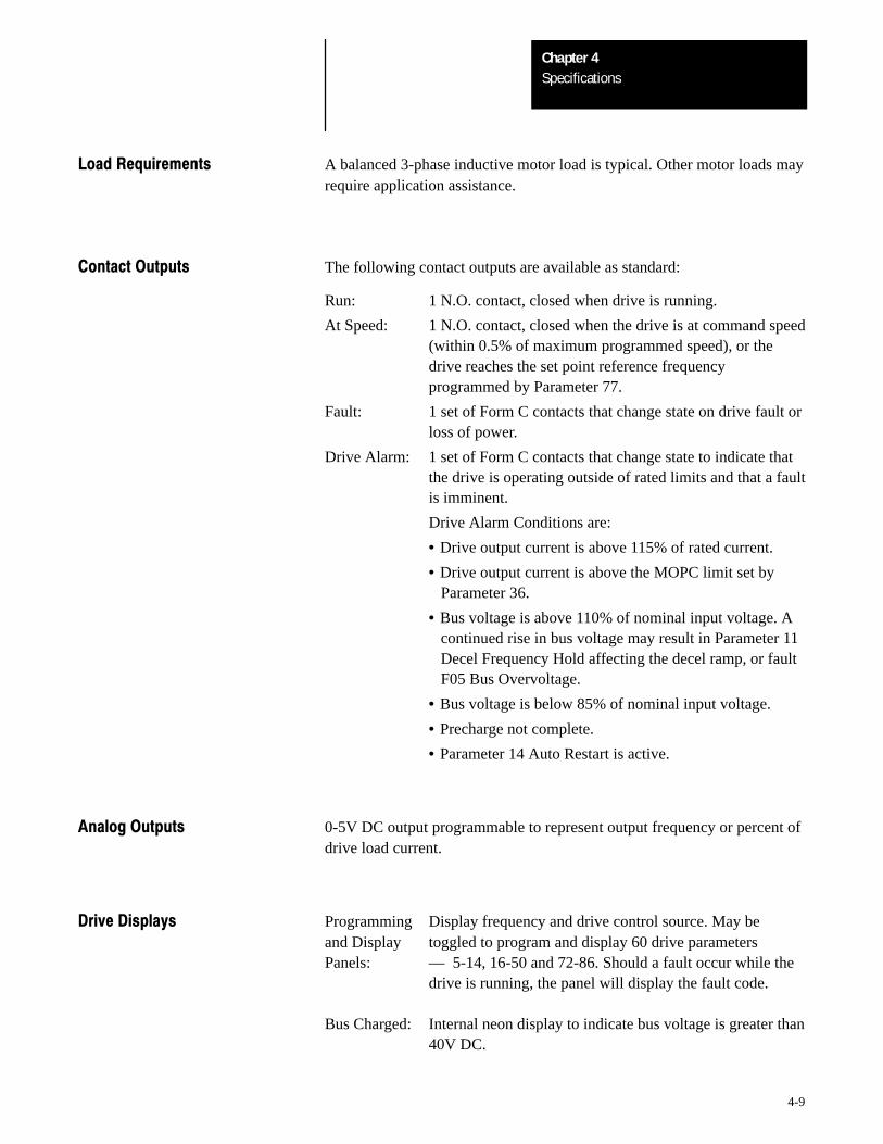
Contact Outputs The following contact outputs are available as standard:
Run: 1 N.O. contact, closed when drive is running.
At Speed: 1 N.O. contact, closed when the drive is at command speed(within 0.5% of maximum programmed speed), or thedrive reaches the set point reference frequencyprogrammed by Parameter 77.
Fault: 1 set of Form C contacts that change state on drive fault orloss of power.
Drive Alarm: 1 set of Form C contacts that change state to indicate thatthe drive is operating outside of rated limits and that a faultis imminent.
Drive Alarm Conditions are:
• Drive output current is above 115% of rated current.
• Drive output current is above the MOPC limit set by Parameter 36.
• Bus voltage is above 110% of nominal input voltage. A continued rise in bus voltage may result in Parameter 11 Decel Frequency Hold affecting the decel ramp, or fault F05 Bus Overvoltage.
• Bus voltage is below 85% of nominal input voltage.
• Precharge not complete.
• Parameter 14 Auto Restart is active.
Analog Outputs 0-5V DC output programmable to represent output frequency or percent ofdrive load current.
Drive Displays Programming Display frequency and drive control source. May be and Display toggled to program and display 60 drive parametersPanels: –– 5-14, 16-50 and 72-86. Should a fault occur while the
drive is running, the panel will display the fault code.
Bus Charged: Internal neon display to indicate bus voltage is greater than40V DC.

SpecificationsChapter 4
4-10
Programmable Parameters The 1336VT drive logic uses a set of 90 user parameters to select andcontrol drive operation. Seventy-one of these parameters are accessiblethrough any of the Programming and Display Panels. All 90 are accessiblethrough the Serial Port.
5Chapter
5-1
Installation
!ATTENTION: An incorrectly applied or installed system canresult in component damage or reduction in product life. The mostcommon causes are:
• Wiring the AC line to drive output or control terminals.
• Improper bypass or output circuits not approved byAllen-Bradley.
• Output circuits which do not connect directly to the motor.
• Incorrect or inadequate AC supply.
• Excessive ambient temperature.
Contact Allen-Bradley for assistance with application or wiring.
General Installation Requirements
The 1336VT must be installed in an area where the following installationand environmental guidelines are met.
• Cabinet mounting is upright, leaving room for a minimum clearance of 4inches (102 mm) on the top and bottom and 2 inches (51 mm) on thesides for proper ventilation.
• The drive is easily accessible for maintenance and troubleshooting.
• The rated altitude does not exceed 3,300 feet (1,000 meters).
• Vibration will be within the ratings outlined in Chapter 4 –Specifications.
• The ambient atmosphere contains no volatile or corrosive gas, vapors ordust.
• The relative humidity does not exceed 95% for all drive ratings.
• The ambient temperature for the drive heatsink is kept within 0 to +40°Cfor all open ratings.
• The ambient temperature for the chassis components is kept within 0 to+50°C.
Important: An input transformer should not be required for normal driveoperation. If the use of an input transformer is desired, only an isolationtype transformer should be used.
Before actual installation, remove all packing material, wedges or bracesfrom within and around the drive.
InstallationChapter 5
5-2
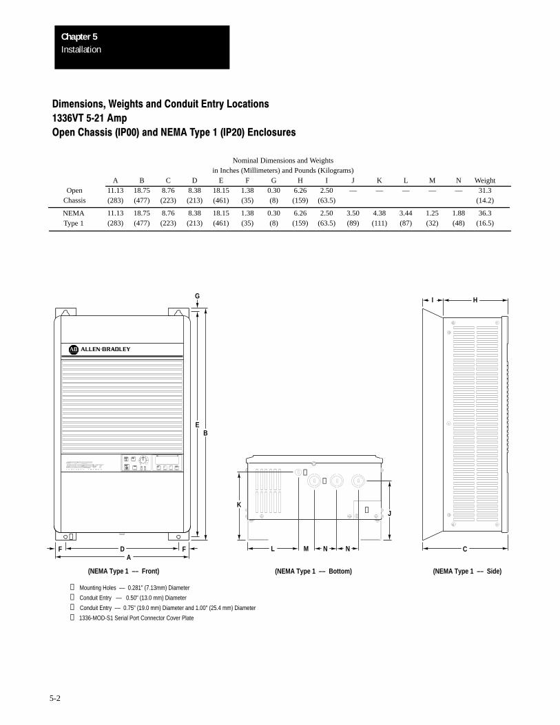
Dimensions, Weights and Conduit Entry Locations
1336VT 521 Amp
Open Chassis (IP00) and NEMA Type 1 (IP20) Enclosures
Nominal Dimensions and Weightsin Inches (Millimeters) and Pounds (Kilograms)
A B C D E F G H I J K L M N Weight11.13 18.75 8.76 8.38 18.15 1.38 0.30 6.26 2.50 — — — — — 31.3(283) (477) (223) (213) (461) (35) (8) (159) (63.5) (14.2)
11.13 18.75 8.76 8.38 18.15 1.38 0.30 6.26 2.50 3.50 4.38 3.44 1.25 1.88 36.3(283) (477) (223) (213) (461) (35) (8) (159) (63.5) (89) (111) (87) (32) (48) (16.5)
OpenChassis
NEMAType 1
PR
Enter
Freq
PR
Jog
Stop
Start
(NEMA Type 1 –– Front)
DFA
F
EB
➊
➊ Mounting Holes –– 0.281" (7.13mm) Diameter
➋ Conduit Entry –– 0.50" (13.0 mm) Diameter
➌ Conduit Entry –– 0.75" (19.0 mm) Diameter and 1.00" (25.4 mm) Diameter
➍ 1336-MOD-S1 Serial Port Connector Cover Plate
G
K
M NL N
J
(NEMA Type 1 –– Bottom)
➌➋
➍
I H
C
(NEMA Type 1 –– Side)
InstallationChapter 5
5-3
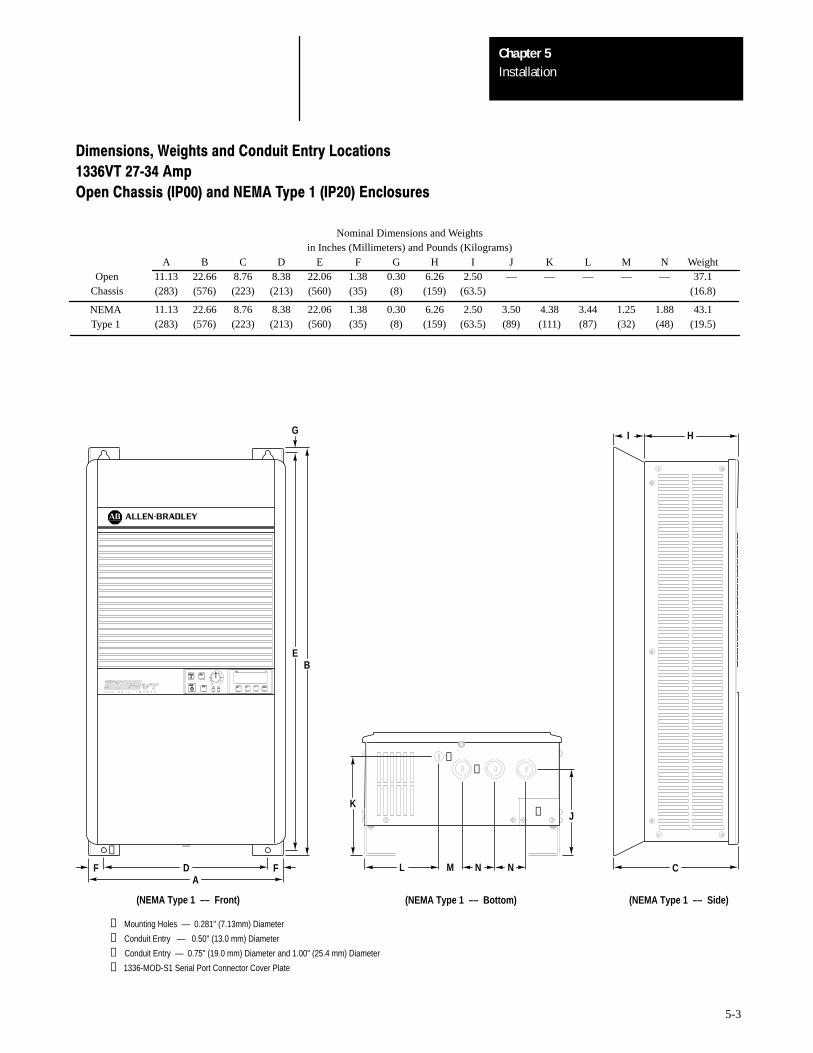
Dimensions, Weights and Conduit Entry Locations
1336VT 2734 Amp
Open Chassis (IP00) and NEMA Type 1 (IP20) Enclosures
Nominal Dimensions and Weightsin Inches (Millimeters) and Pounds (Kilograms)
A B C D E F G H I J K L M N Weight11.13 22.66 8.76 8.38 22.06 1.38 0.30 6.26 2.50 — — — — — 37.1(283) (576) (223) (213) (560) (35) (8) (159) (63.5) (16.8)
11.13 22.66 8.76 8.38 22.06 1.38 0.30 6.26 2.50 3.50 4.38 3.44 1.25 1.88 43.1(283) (576) (223) (213) (560) (35) (8) (159) (63.5) (89) (111) (87) (32) (48) (19.5)
OpenChassis
NEMAType 1
PR
Enter
Freq
PR
Jog
Stop
Start
(NEMA Type 1 –– Front)
DFA
F
EB
K
M NL N
J
(NEMA Type 1 –– Bottom)
I H
C
(NEMA Type 1 –– Side)
➊
➊ Mounting Holes –– 0.281" (7.13mm) Diameter
➋ Conduit Entry –– 0.50" (13.0 mm) Diameter
➌ Conduit Entry –– 0.75" (19.0 mm) Diameter and 1.00" (25.4 mm) Diameter
➍ 1336-MOD-S1 Serial Port Connector Cover Plate
➌➋
➍
G
InstallationChapter 5
5-4
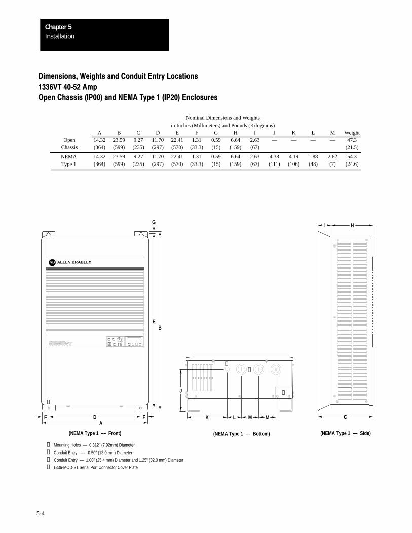
Dimensions, Weights and Conduit Entry Locations
1336VT 4052 Amp
Open Chassis (IP00) and NEMA Type 1 (IP20) Enclosures
Nominal Dimensions and Weightsin Inches (Millimeters) and Pounds (Kilograms)
A B C D E F G H I J K L M Weight14.32 23.59 9.27 11.70 22.41 1.31 0.59 6.64 2.63 — — — — 47.3(364) (599) (235) (297) (570) (33.3) (15) (159) (67) (21.5)
14.32 23.59 9.27 11.70 22.41 1.31 0.59 6.64 2.63 4.38 4.19 1.88 2.62 54.3(364) (599) (235) (297) (570) (33.3) (15) (159) (67) (111) (106) (48) (7) (24.6)
OpenChassis
NEMAType 1
J
K
(NEMA Type 1 –– Bottom)
L M M
➌➋
➍
I H
C
(NEMA Type 1 –– Side)
PR
Enter
Freq
PR
Jog
Stop
Start
(NEMA Type 1 –– Front)
DFA
F
EB
➊ Mounting Holes –– 0.312" (7.92mm) Diameter
➋ Conduit Entry –– 0.50" (13.0 mm) Diameter
➌ Conduit Entry –– 1.00" (25.4 mm) Diameter and 1.25" (32.0 mm) Diameter
➍ 1336-MOD-S1 Serial Port Connector Cover Plate
G
➊
InstallationChapter 5
5-5
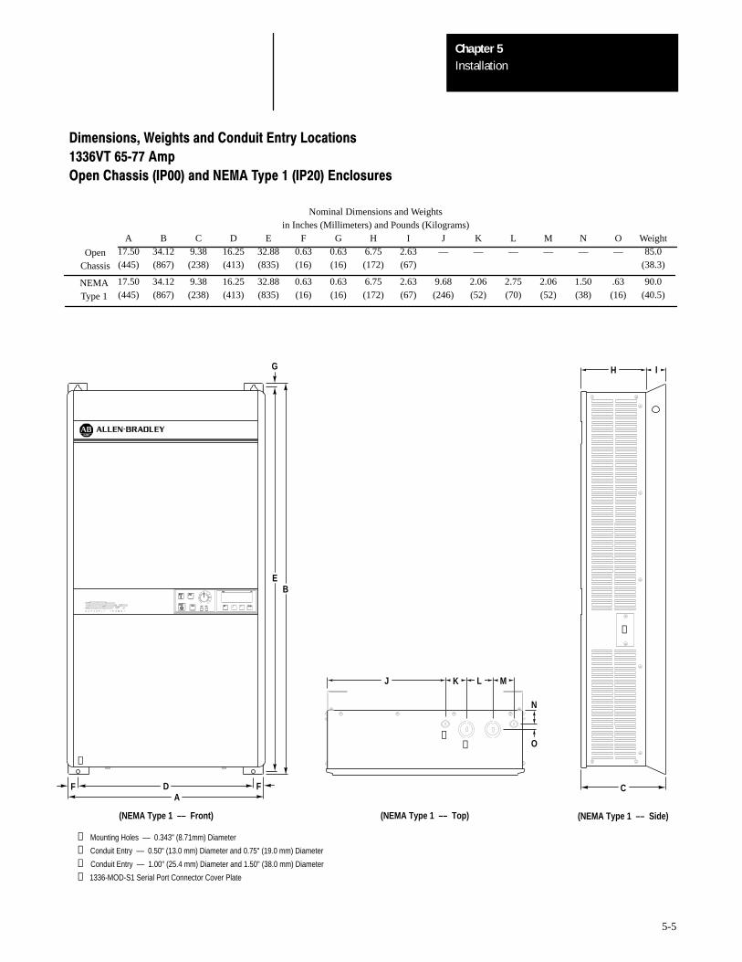
Dimensions, Weights and Conduit Entry Locations
1336VT 6577 Amp
Open Chassis (IP00) and NEMA Type 1 (IP20) Enclosures
Nominal Dimensions and Weightsin Inches (Millimeters) and Pounds (Kilograms)
A B C D E F G H I J K L M N O Weight17.50 34.12 9.38 16.25 32.88 0.63 0.63 6.75 2.63 — — — — — — 85.0(445) (867) (238) (413) (835) (16) (16) (172) (67) (38.3)
17.50 34.12 9.38 16.25 32.88 0.63 0.63 6.75 2.63 9.68 2.06 2.75 2.06 1.50 .63 90.0(445) (867) (238) (413) (835) (16) (16) (172) (67) (246) (52) (70) (52) (38) (16) (40.5)
OpenChassis
NEMAType 1
PR
Enter
Freq
PR
Jog
Stop
Start
(NEMA Type 1 –– Front)
DFA
F
EB
➊ Mounting Holes –– 0.343" (8.71mm) Diameter
➋ Conduit Entry –– 0.50" (13.0 mm) Diameter and 0.75" (19.0 mm) Diameter
➌ Conduit Entry –– 1.00" (25.4 mm) Diameter and 1.50" (38.0 mm) Diameter
➍ 1336-MOD-S1 Serial Port Connector Cover Plate
G
➊
➌➋
J LK M
O
N
(NEMA Type 1 –– Top)
➍
IH
C
(NEMA Type 1 –– Side)
InstallationChapter 5
5-6
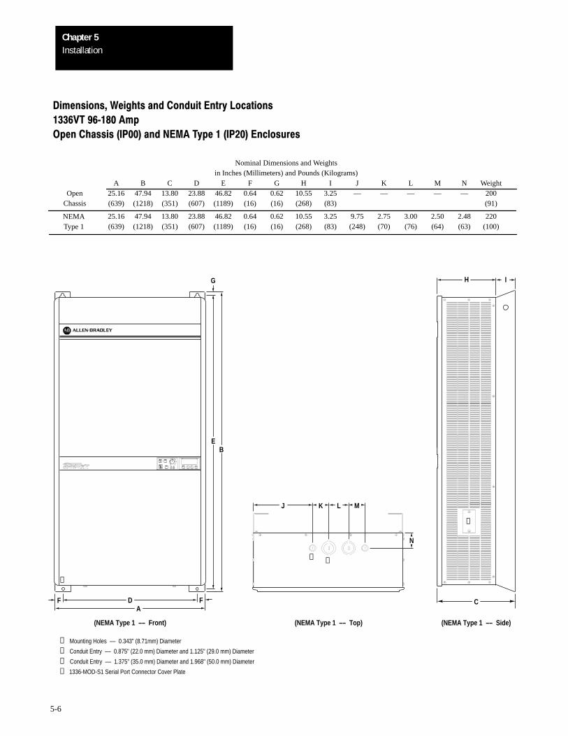
Dimensions, Weights and Conduit Entry Locations
1336VT 96180 Amp
Open Chassis (IP00) and NEMA Type 1 (IP20) Enclosures
Nominal Dimensions and Weightsin Inches (Millimeters) and Pounds (Kilograms)
A B C D E F G H I J K L M N Weight25.16 47.94 13.80 23.88 46.82 0.64 0.62 10.55 3.25 — — — — — 200(639) (1218) (351) (607) (1189) (16) (16) (268) (83) (91)
25.16 47.94 13.80 23.88 46.82 0.64 0.62 10.55 3.25 9.75 2.75 3.00 2.50 2.48 220(639) (1218) (351) (607) (1189) (16) (16) (268) (83) (248) (70) (76) (64) (63) (100)
OpenChassis
NEMAType 1
PR
Enter
Freq
PR
Jog
Stop
Start
(NEMA Type 1 –– Front)
➊ Mounting Holes –– 0.343" (8.71mm) Diameter
➋ Conduit Entry –– 0.875" (22.0 mm) Diameter and 1.125" (29.0 mm) Diameter
➌ Conduit Entry –– 1.375" (35.0 mm) Diameter and 1.968" (50.0 mm) Diameter
➍ 1336-MOD-S1 Serial Port Connector Cover Plate
EB
G
DFA
F
➊
➌➋
LJ
(NEMA Type 1 –– Top)
K M
N
C
(NEMA Type 1 –– Side)
IH
➍
InstallationChapter 5
5-7
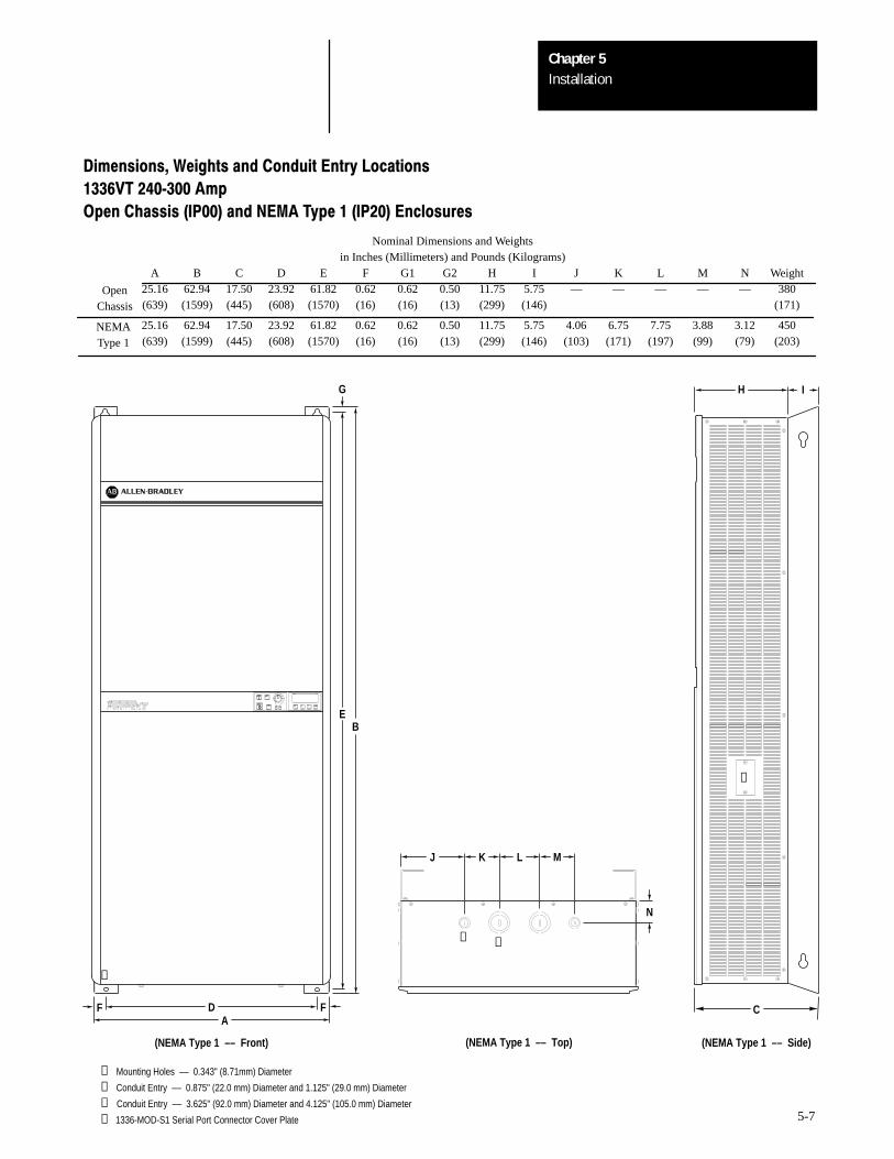
Dimensions, Weights and Conduit Entry Locations
1336VT 240300 Amp
Open Chassis (IP00) and NEMA Type 1 (IP20) Enclosures
Nominal Dimensions and Weightsin Inches (Millimeters) and Pounds (Kilograms)
A B C D E F G1 G2 H I J K L M N Weight25.16 62.94 17.50 23.92 61.82 0.62 0.62 0.50 11.75 5.75 — — — — — 380(639) (1599) (445) (608) (1570) (16) (16) (13) (299) (146) (171)
25.16 62.94 17.50 23.92 61.82 0.62 0.62 0.50 11.75 5.75 4.06 6.75 7.75 3.88 3.12 450(639) (1599) (445) (608) (1570) (16) (16) (13) (299) (146) (103) (171) (197) (99) (79) (203)
OpenChassis
NEMAType 1
PR
Enter
Freq
PR
Jog
Stop
Start
EB
G
IH➍
(NEMA Type 1 –– Front)
➊ Mounting Holes –– 0.343" (8.71mm) Diameter
➋ Conduit Entry –– 0.875" (22.0 mm) Diameter and 1.125" (29.0 mm) Diameter
➌ Conduit Entry –– 3.625" (92.0 mm) Diameter and 4.125" (105.0 mm) Diameter
➍ 1336-MOD-S1 Serial Port Connector Cover Plate
DFA
F
➊
➌➋
J
(NEMA Type 1 –– Top)
K M
N
L
C
(NEMA Type 1 –– Side)
6Chapter
6-1
Wiring
!ATTENTION: Do not proceed without reading the information on thispage. Failure to understand procedures and hazards may result in personalinjury or equipment damage.
General Wiring Procedures
!ATTENTION: An incorrectly applied or installed system can result incomponent damage or reduction in product life. The most common causesare:• Wiring the AC line to drive output or control terminals.• Improper bypass or output circuits not approved by Allen-Bradley.• Output circuits which do not connect directly to the motor.• Incorrect or inadequate AC supply.• Excessive ambient temperature.
Contact Allen-Bradley for assistance with application or wiring.
1. The National Electrical Code requires that a circuit breaker or fusible disconnectswitch be provided in the drive branch circuit. Providing drive input fusingalone is not sufficient to meet NEC guidelines. The 1336VT does not providethis requirement. Selection of a branch circuit breaker or fusible disconnectshould be based on the drive input current rating. Refer to the Terminal BlockTB1 Wiring sections in this chapter for mandatory AC input fusingrecommendations for drive short circuit protection.
2. The National Electrical Code and local regulations govern the installation andwiring of the 1336VT. All input and output power wiring, control wiring andconduit must be brought through the drive conduit entry holes provided on theenclosure. Connections to the drive must be made as shown in the followingsections and in accordance with the drive nameplate, National Electrical Coderequirements and any additional interconnection diagrams packed with thedrive.
3. The voltage on each phase of the incoming line to the drive must match thedrive input rating. Verify the drive rating by referring to the input voltage listedon the drive nameplate. If the incoming line voltage is out of this tolerance,equipment may be damaged or fail to operate.
4. If multiple drives are used, do not use common cabling for AC input or outputleads. If multiconductor cable is used, separate 3-conductor input and outputcable for each drive must be used.
5. All signal wiring must be run separate from power or control wiring. Verify thatshielded cable and/or conduit is used if indicated on any interconnectiondiagrams or in the following sections. If shielded cable is required, shields mustbe grounded at the drive end only at one of the drive ground lugs provided.
6. Nearby relays, solenoids or brake coils can produce electrical noise transientsand cause erratic drive behavior. Transient suppression networks must be addedacross the coils of these devices.
7. Since most startup difficulties result from incorrect wiring, every precautionshould be taken to assure that the wiring is as indicated on the diagrams andinformation packed with the drive.
WiringChapter 6
6-2
Input Power Conditioning Typically, the 1336VT is suitable for direct connection to a correct voltage,three phase, AC power line. There are, however, certain power lineconditions which will greatly increase the possibility of drive input powercomponent malfunction. To reduce the possibility of these malfunctions, aline reactor or isolation type transformer may be required.
The basic rules for determining if a line reactor or isolation typetransformer is required are as follows:
1. If the AC line supplying the drive has power factor correction capacitorsconnected, an AC line reactor or isolation type transformer must beconnected between the capacitor bank and the input to the drive.
2. If the AC line frequently experiences transient power interruptions ofsignificant voltage spikes, an AC line reactor or isolation typetransformer should be used.
Ungrounded Distribution Systems
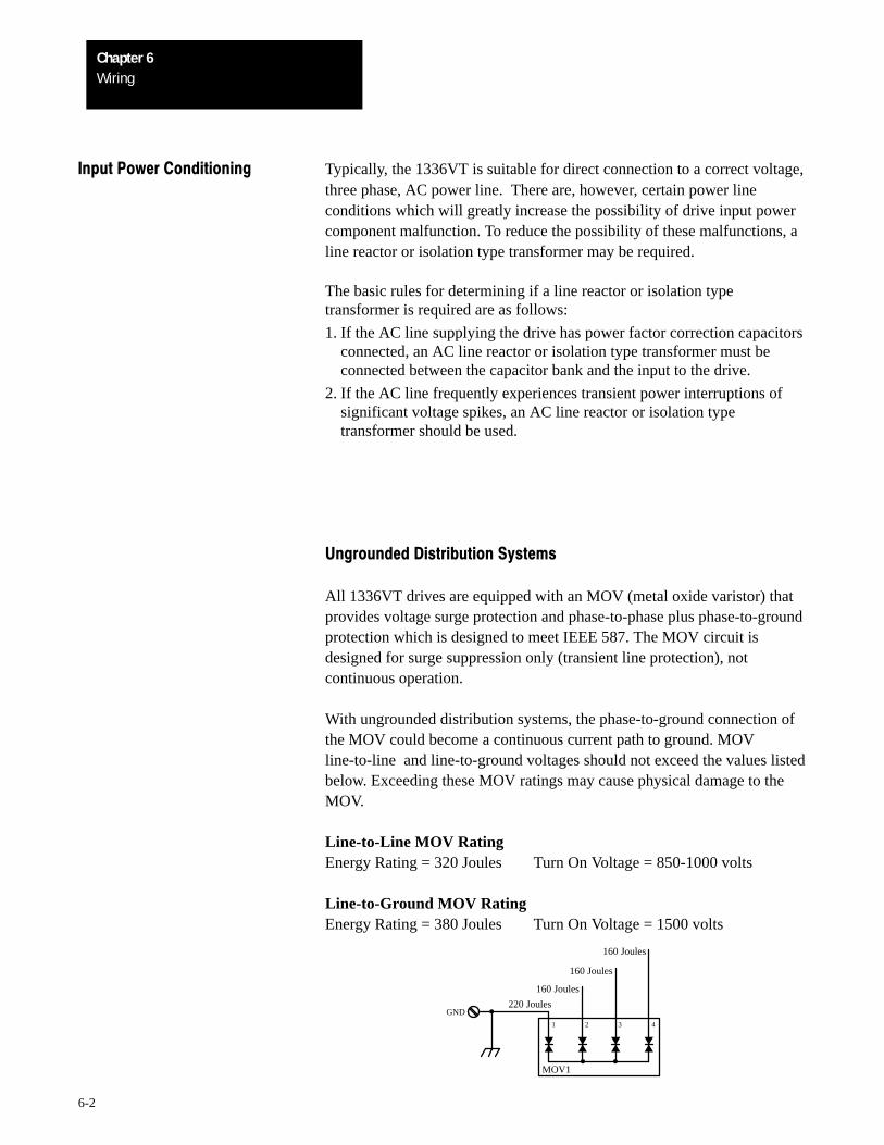
All 1336VT drives are equipped with an MOV (metal oxide varistor) thatprovides voltage surge protection and phase-to-phase plus phase-to-groundprotection which is designed to meet IEEE 587. The MOV circuit isdesigned for surge suppression only (transient line protection), notcontinuous operation.
With ungrounded distribution systems, the phase-to-ground connection ofthe MOV could become a continuous current path to ground. MOVline-to-line and line-to-ground voltages should not exceed the values listedbelow. Exceeding these MOV ratings may cause physical damage to theMOV.
Line-to-Line MOV RatingEnergy Rating = 320 Joules Turn On Voltage = 850-1000 volts
Line-to-Ground MOV RatingEnergy Rating = 380 Joules Turn On Voltage = 1500 volts
4321
GND
MOV1
220 Joules
160 Joules
160 Joules
160 Joules
WiringChapter 6
6-3
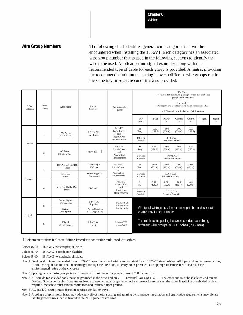
Wire Group Numbers The following chart identifies general wire categories that will beencountered when installing the 1336VT. Each category has an associatedwire group number that is used in the following sections to identify thewire to be used. Application and signal examples along with therecommended type of cable for each group is provided. A matrix providingthe recommended minimum spacing between different wire groups run inthe same tray or separate conduit is also provided.
WireCategory
WireGroup
Application
AC Power(> 600 V AC)
AC Power(to 600 V AC)
115VAC or 115V DCLogic
24V AC or 24V DCLogic
115V ACPower
Analog SignalsDC Supplies
Digital (Low Speed)
Digital (High Speed)
SignalExample
2.3 KV, 3∅AC Lines
480V, 3∅
Relay LogicPLC I/O
PLC I/O
Power SuppliesInstruments
5-24V DCSupplies
Power SuppliesTTL Logic Level
Pulse Train Input
RecommendedCable
Per NECLocal Codes
andApplication
Requirements
Belden 8760Belden 8770Belden 9460
Belden 8760Belden 9460
Per NECLocal Codes
andApplication
Requirements
Per NECLocal Codes
andApplication
Requirements
Per NECLocal Codes
andApplication
Requirements
9.00(228.6)
3.00 (76.2)Between Conduit
BetweenConduit
BetweenConduit
BetweenConduit
BetweenConduit
InTray
InTray
InTray
InTray
9.00(228.6)
9.00(228.6)
9.00(228.6)
9.00(228.6)
9.00(228.6)
6.00(152.4)
6.00(152.4)
9.00(228.6)
6.00(152.4)
9.00(228.6)
6.00(152.4)
9.00(228.6)
6.00(152.4)
6.00(152.4)
9.00(228.6)
3.00 (76.2)Between Conduit
3.00 (76.2)Between Conduit
3.00 (76.2)Between Conduit
For Tray:Recommended minimum spacing between different wire
groups in the same tray
For Conduit:Different wire groups must be run in separate conduit
All Dimensions in Inches and (Millimeters)
WireGroup
Power1
Power2
Control3
Control4
Signal5
Signal6
Power
Signal
Control
1
2
3
4
5
6
All signal wiring must be run in separate steel conduit. A wire tray is not suitable. The minimum spacing between conduit containing different wire groups is 3.00 inches (78.2 mm).
❶
❶ Refer to precautions in General Wiring Procedures concerning multi-conductor cables.
Belden 8760 — 18 AWG, twisted pair, shielded.
Belden 8770 — 18 AWG, 3 conductor, shielded.
Belden 9460 — 18 AWG, twisted pair, shielded.
Note 1 Steel conduit is recommended for all 1336VT power or control wiring and required for all 1336VT signal wiring. All input and output power wiring,control wiring or conduit should be brought through the drive conduit entry holes provided. Use appropriate connectors to maintain theenvironmental rating of the enclosure.
Note 2 Spacing between wire groups is the recommended minimum for parallel runs of 200 feet or less.
Note 3 All shields for shielded cable must be grounded at the drive end only –– Terminal 3 or 4 of TB2 –– The other end must be insulated and remainfloating. Shields for cables from one enclosure to another must be grounded only at the enclosure nearest the drive. If splicing of shielded cables isrequired, the shield must remain continuous and insulated from ground.
Note 4 AC and DC circuits must be run in separate conduit or trays.
Note 5 A voltage drop in motor leads may adversely affect motor starting and running performance. Installation and application requirements may dictatethat larger wire sizes than indicated in the NEC guidelines be used.
WiringChapter 6
6-4
Terminal Block TB1 Power Wiring Input and output power connections are marked on terminal block TB1, aten position terminal block on the drive backpanel. For maintenance andsetup procedures, the drive may be operated without a motor connected.
Important:
1. The 1336VT does not provide input power short circuit fusing.Specifications for the recommended fuse size and type to provide driveinput power protection against short circuits are provided on thefollowing pages. Branch circuit breakers or disconnect switches cannotprovide this level of protection for drive components.
2. Each Bulletin 1336VT must have its own dedicated input and outputpower leads. If multiconductor cable is used, separate 3-conductor inputand output cable for each drive must be used.
3. For multimotor operation, the combined total of motor full load currentmust not exceed the rated output current of the drive.
4. Verify that the motor windings are properly connected to receive the fulldrive output voltage rating.
5. For 5-77 Amp drive ratings, two ground terminals have been provided atTB1. Either one of these terminals must be connected to earth ground orthe ground of the building system.
For 96-300 Amp drive ratings, one ground terminal that will accept twoground leads has been provided at TB1. Connect this terminal to earthground or the ground of the building system.
WiringChapter 6
6-5
!ATTENTION:
1. Any disconnecting means wired to drive output terminals M1,M2 and M3 must be capable of stopping the drive if openedduring drive operation. If opened during drive operation, thedrive will continue to produce output voltage into an open motorcircuit causing a potential shock hazard.
2. The start/stop control circuitry in the 1336VT includessolid-state components. If hazards due to accidental contact withmoving machinery or unintentional flow of liquid, gas or solidsexist, an additional hard wired stop circuit is required to removeAC line power to the drive. When AC input power is removed,there will be a loss of inherent regenerative braking effect andthe motor will coast to a stop. An auxiliary braking method maybe required.
The 1336VT is intended to be controlled by control input signalsthat will start and stop the motor. A device that routinelydisconnects then reapplies line power to the drive for the purposeof starting and stopping the motor must not be used. After ahard wired stop has been initiated, allow at least one minutebefore reapplying input power to the drive. The allowablenumber of hard wired start/stops are 3 cycles within a 5 minuteperiod. Wait 10 minutes before attempting the next 3 hard wiredstop cycle to allow the drive precharge resistors to cool.
Refer to codes and standards applicable to your particular systemfor specific requirements and additional information.
WiringChapter 6
6-6
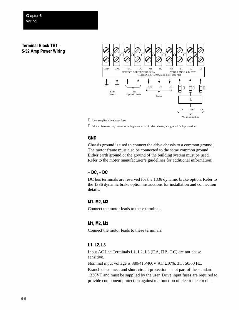
Terminal Block TB1 -552Amp Power Wiring
AC Incoming Line
GND GND +DC –DC M1 M2 M3 L1 L2 L3
Motor
∅ A
∅ A
USE 75°C COPPER WIRE ONLY WIRE RANGE 6–14 AWGTIGHTENING TORQUE 20 INCH POUNDS
∅ B ∅ C
∅ B ∅ C
❶ ❶ ❶
❷
EarthGround
1336Dynamic Brake
❶ User supplied drive input fuses.
❷ Motor disconnecting means including branch circuit, short circuit, and ground fault protection.
GND
Chassis ground is used to connect the drive chassis to a common ground.The motor frame must also be connected to the same common ground.Either earth ground or the ground of the building system must be used.Refer to the motor manufacturer’s guidelines for additional information.
+ DC, - DC
DC bus terminals are reserved for the 1336 dynamic brake option. Refer tothe 1336 dynamic brake option instructions for installation and connectiondetails.
M1, M2, M3
Connect the motor leads to these terminals.
M1, M2, M3
Connect the motor leads to these terminals.
L1, L2, L3
Input AC line Terminals L1, L2, L3 (∅ A, ∅ B, ∅ C) are not phasesensitive.
Nominal input voltage is 380/415/460V AC ±10%, 3∅ , 50/60 Hz.
Branch disconnect and short circuit protection is not part of the standard1336VT and must be supplied by the user. Drive input fuses are required toprovide component protection against malfunction of electronic circuits.
WiringChapter 6
6-7
Terminal Block TB1 -552Amp Power Wiring (cont.)
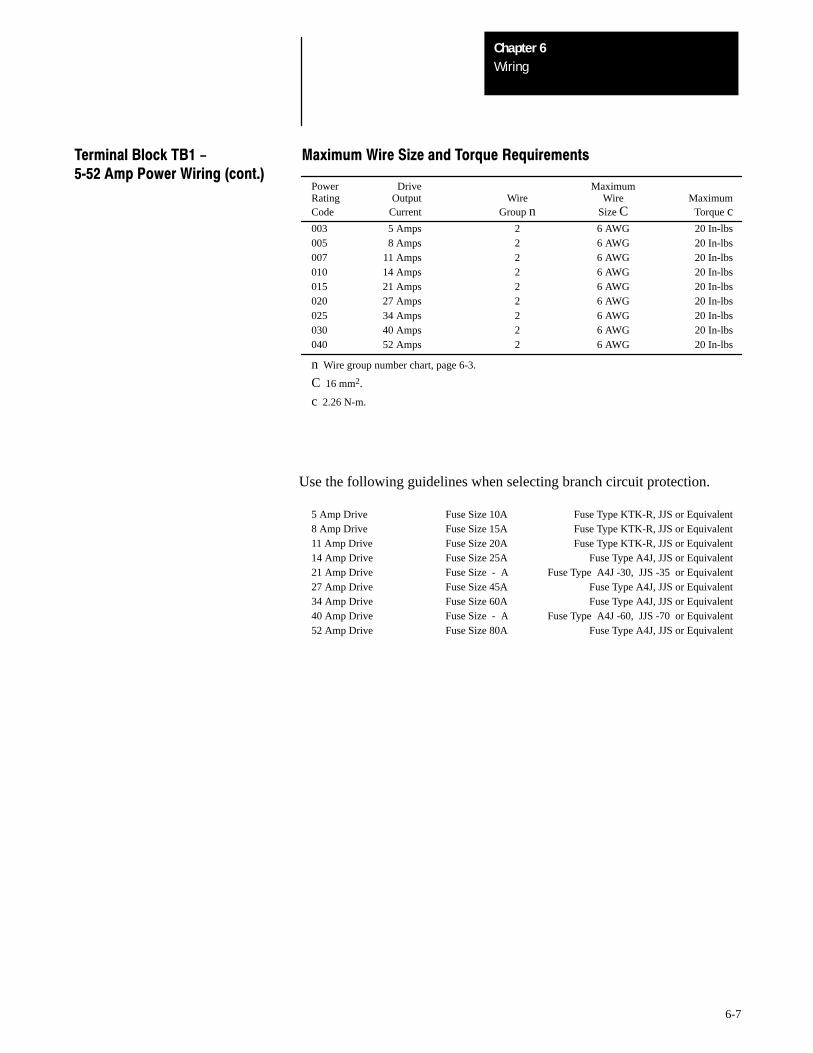
Power Drive MaximumRating Output Wire Wire MaximumCode Current Group n Size C Torque c003 5 Amps 2 6 AWG 20 In-lbs005 8 Amps 2 6 AWG 20 In-lbs007 11 Amps 2 6 AWG 20 In-lbs010 14 Amps 2 6 AWG 20 In-lbs015 21 Amps 2 6 AWG 20 In-lbs020 27 Amps 2 6 AWG 20 In-lbs025 34 Amps 2 6 AWG 20 In-lbs030 40 Amps 2 6 AWG 20 In-lbs040 52 Amps 2 6 AWG 20 In-lbs
n Wire group number chart, page 6-3.
C 16 mm2.
c 2.26 N-m.
Maximum Wire Size and Torque Requirements
Use the following guidelines when selecting branch circuit protection.
5 Amp Drive Fuse Size 10A Fuse Type KTK-R, JJS or Equivalent8 Amp Drive Fuse Size 15A Fuse Type KTK-R, JJS or Equivalent11 Amp Drive Fuse Size 20A Fuse Type KTK-R, JJS or Equivalent14 Amp Drive Fuse Size 25A Fuse Type A4J, JJS or Equivalent21 Amp Drive Fuse Size - A Fuse Type A4J -30, JJS -35 or Equivalent27 Amp Drive Fuse Size 45A Fuse Type A4J, JJS or Equivalent34 Amp Drive Fuse Size 60A Fuse Type A4J, JJS or Equivalent40 Amp Drive Fuse Size - A Fuse Type A4J -60, JJS -70 or Equivalent52 Amp Drive Fuse Size 80A Fuse Type A4J, JJS or Equivalent
WiringChapter 6
6-8
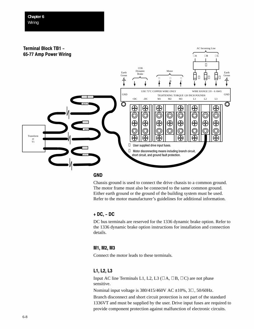
Terminal Block TB1 -6577Amp Power Wiring
GND
+DC –DC M1 M2 M3 L1 L2 L3
GND
∅A
TransformerT1
∅B
∅C
∅ A ∅ B ∅ C
❶ ❶ ❶
EarthGroun
d
1336Dynamic
BrakeMotor
AC Incoming Line
EarthGroun
d
USE 75°C COPPER WIRE ONLY WIRE RANGE 2/0 – 6 AWG
TIGHTENING TORQUE 120 INCH POUNDS
❶ User supplied drive input fuses.
❷ Motor disconnecting means including branch circuit, short circuit, and ground fault protection.
460V
380V
415V
❷
GND
Chassis ground is used to connect the drive chassis to a common ground.The motor frame must also be connected to the same common ground.Either earth ground or the ground of the building system must be used.Refer to the motor manufacturer’s guidelines for additional information.
+ DC, - DC
DC bus terminals are reserved for the 1336 dynamic brake option. Refer tothe 1336 dynamic brake option instructions for installation and connectiondetails.
M1, M2, M3
Connect the motor leads to these terminals.
L1, L2, L3
Input AC line Terminals L1, L2, L3 (∅ A, ∅ B, ∅ C) are not phasesensitive.
Nominal input voltage is 380/415/460V AC ±10%, 3∅ , 50/60Hz.
Branch disconnect and short circuit protection is not part of the standard1336VT and must be supplied by the user. Drive input fuses are required toprovide component protection against malfunction of electronic circuits.
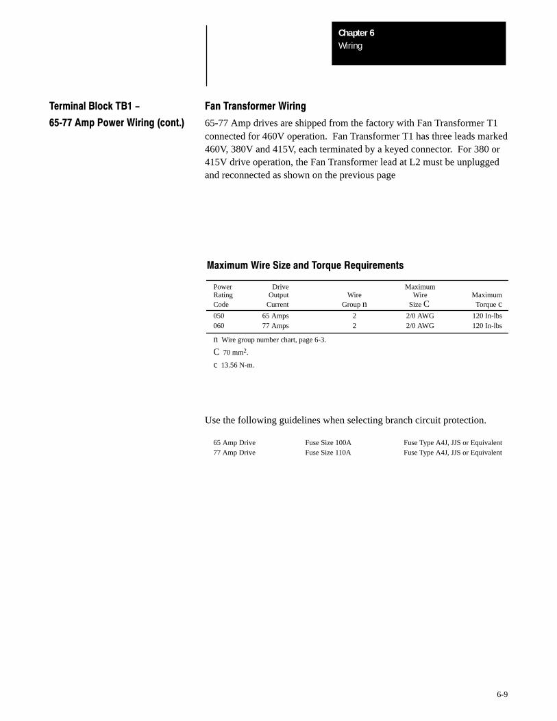
WiringChapter 6
6-9
Terminal Block TB1 - Fan Transformer Wiring
6577Amp Power Wiring (cont.) 65-77 Amp drives are shipped from the factory with Fan Transformer T1connected for 460V operation. Fan Transformer T1 has three leads marked460V, 380V and 415V, each terminated by a keyed connector. For 380 or415V drive operation, the Fan Transformer lead at L2 must be unpluggedand reconnected as shown on the previous page
Maximum Wire Size and Torque Requirements
Power Drive MaximumRating Output Wire Wire MaximumCode Current Group n Size C Torque c050 65 Amps 2 2/0 AWG 120 In-lbs060 77 Amps 2 2/0 AWG 120 In-lbs
n Wire group number chart, page 6-3.
C 70 mm2.
c 13.56 N-m.
Use the following guidelines when selecting branch circuit protection.
65 Amp Drive Fuse Size 100A Fuse Type A4J, JJS or Equivalent77 Amp Drive Fuse Size 110A Fuse Type A4J, JJS or Equivalent

WiringChapter 6
6-10
Terminal Block TB1 -96156Amp Power Wiring
+DC –DC M1 M2 M3 L1 L2 L3
∅A
∅B
∅C
∅ A ∅ B ∅ C
❶ ❶ ❶
1336Dynamic
BrakeMotor
AC Incoming Line
USE 75°C COPPER WIRE ONLY WIRE RANGE 2/0 – 6 AWG
TIGHTENING TORQUE 120 INCH POUNDS
❶ User supplied drive input fuses.
❷ Motor disconnecting means including branch circuit, short circuit, and ground fault protection.
GND
EarthGroun
d
❷
GND
Chassis ground is used to connect the drive chassis to a common ground.The motor frame must also be connected to the same common ground.Either earth ground or the ground of the building system must be used.Refer to the motor manufacturer’s guidelines for additional information.
+ DC, - DC
DC bus terminals are reserved for the 1336 dynamic brake option. Refer tothe 1336 dynamic brake option instructions for installation and connectiondetails.
M1, M2, M3
Connect the motor leads to these terminals.
L1, L2, L3
Input AC line Terminals L1, L2, L3 (∅ A, ∅ B, ∅ C) are not phasesensitive.
For drives rated B075, nominal input voltage is 380/415/460V AC ±10%,3∅ , 50/60 Hz.
Branch disconnect and short circuit protection is not part of the standard1336VT and must be supplied by the user. Drive input fuses are required toprovide component protection against malfunction of electronic circuits.
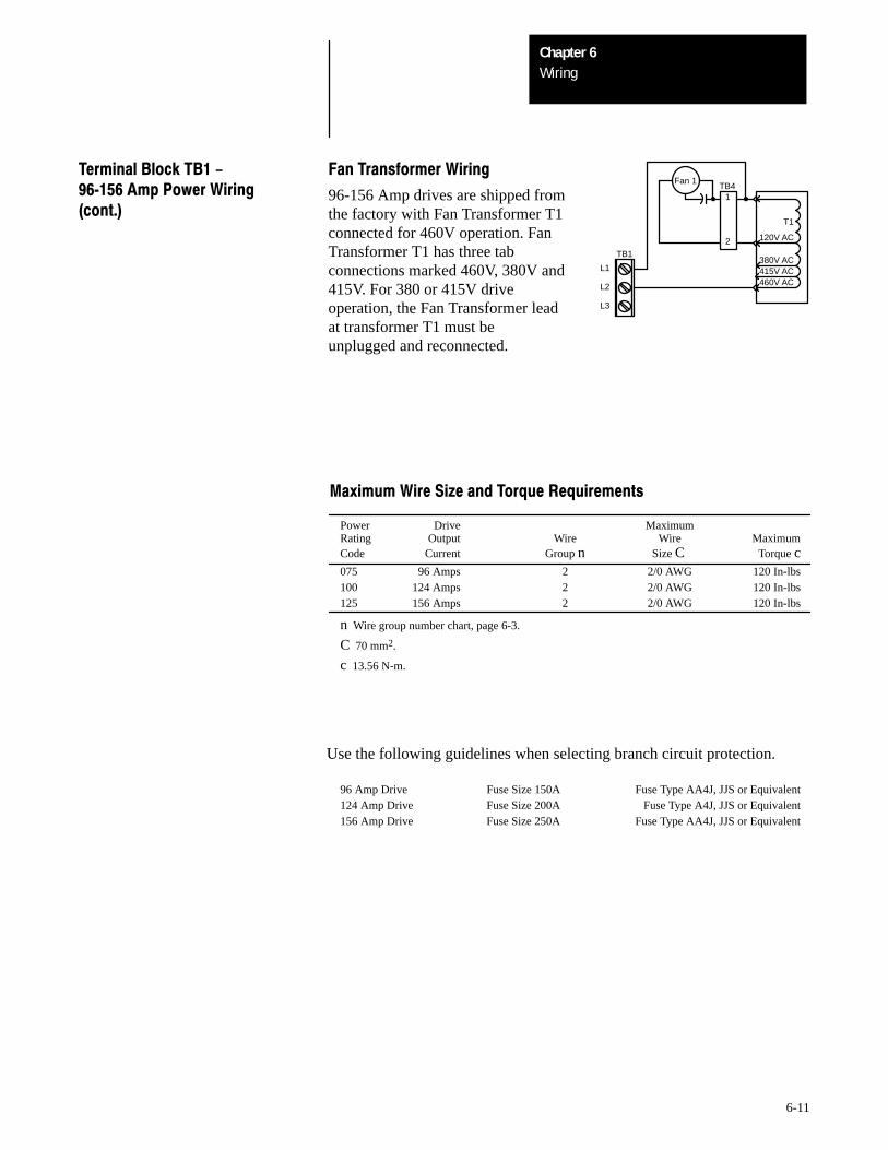
WiringChapter 6
6-11
TB1
L1
L2
L3
Fan 1
T1
415V AC380V AC
460V AC
120V AC
1
2
TB4
Fan Transformer Wiring
96-156 Amp drives are shipped fromthe factory with Fan Transformer T1connected for 460V operation. FanTransformer T1 has three tabconnections marked 460V, 380V and415V. For 380 or 415V driveoperation, the Fan Transformer leadat transformer T1 must beunplugged and reconnected.
Terminal Block TB1 -96156Amp Power Wiring(cont.)
Maximum Wire Size and Torque Requirements
Power Drive MaximumRating Output Wire Wire MaximumCode Current Group n Size C Torque c075 96 Amps 2 2/0 AWG 120 In-lbs100 124 Amps 2 2/0 AWG 120 In-lbs125 156 Amps 2 2/0 AWG 120 In-lbs
n Wire group number chart, page 6-3.
C 70 mm2.
c 13.56 N-m.
Use the following guidelines when selecting branch circuit protection.
96 Amp Drive Fuse Size 150A Fuse Type AA4J, JJS or Equivalent124 Amp Drive Fuse Size 200A Fuse Type A4J, JJS or Equivalent156 Amp Drive Fuse Size 250A Fuse Type AA4J, JJS or Equivalent
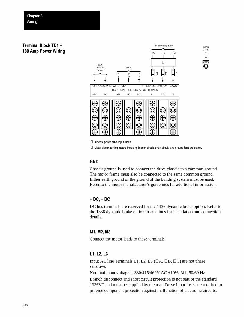
WiringChapter 6
6-12
Terminal Block TB1 -180Amp Power Wiring
+DC –DC M1 M2 M3 L1 L2 L3
∅A
∅B
∅C
∅ A ∅ B ∅ C
❶ ❶ ❶
1336Dynamic
BrakeMotor
AC Incoming Line
USE 75°C COPPER WIRE ONLY WIRE RANGE 350 MCM – 6 AWG
TIGHTENING TORQUE 275 INCH POUNDS
❶ User supplied drive input fuses.
❷ Motor disconnecting means including branch circuit, short circuit, and ground fault protection.
GND
EarthGroun
d
❷
GND
Chassis ground is used to connect the drive chassis to a common ground.The motor frame must also be connected to the same common ground.Either earth ground or the ground of the building system must be used.Refer to the motor manufacturer’s guidelines for additional information.
+ DC, - DC
DC bus terminals are reserved for the 1336 dynamic brake option. Refer tothe 1336 dynamic brake option instructions for installation and connectiondetails.
M1, M2, M3
Connect the motor leads to these terminals.
L1, L2, L3
Input AC line Terminals L1, L2, L3 (∅ A, ∅ B, ∅ C) are not phasesensitive.
Nominal input voltage is 380/415/460V AC ±10%, 3∅ , 50/60 Hz.
Branch disconnect and short circuit protection is not part of the standard1336VT and must be supplied by the user. Drive input fuses are required toprovide component protection against malfunction of electronic circuits.
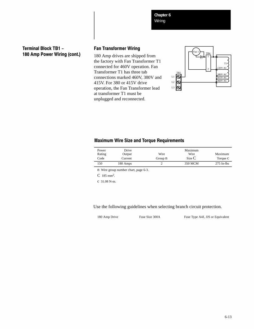
WiringChapter 6
6-13
TB1
L1
L2
L3
Fan 1
T1
415V AC380V AC
460V AC
120V AC
1
2
TB4
Fan Transformer Wiring
180 Amp drives are shipped fromthe factory with Fan Transformer T1connected for 460V operation. FanTransformer T1 has three tabconnections marked 460V, 380V and415V. For 380 or 415V driveoperation, the Fan Transformer leadat transformer T1 must beunplugged and reconnected.
Terminal Block TB1 -180Amp Power Wiring (cont.)
Maximum Wire Size and Torque Requirements
Power Drive MaximumRating Output Wire Wire MaximumCode Current Group n Size C Torque c150 180 Amps 2 350 MCM 275 In-lbs
n Wire group number chart, page 6-3.
C 185 mm2.
c 31.08 N-m.
Use the following guidelines when selecting branch circuit protection.
180 Amp Drive Fuse Size 300A Fuse Type A4J, JJS or Equivalent
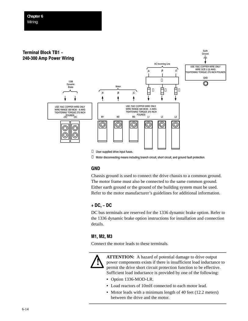
WiringChapter 6
6-14
+DC -DC M1 M2 M3 L1 L2 L3
USE 755C COPPER WIRE ONLYWIRE RANGE 350 MCM - 6 AWGTIGHTENING TORQUE 275 INCH
POUNDS
USE 755C COPPER WIRE ONLY.WIRE RANGE 500 MCM - 0 AWGTIGHTENING TORQUE 375 INCH
POUNDS
jA
jB
jC
jA
jB
jC
❶ ❶ ❶
Terminal Block TB1 -240300Amp Power Wiring
Motor
AC Incoming Line
1336Dynamic
Brake
EarthGround
USE 755C COPPER WIRE ONLYWIRE SIZE 2 (3) AWG
TIGHTENING TORQUE 275 INCH POUNDS
GND❷
❶ User supplied drive input fuses.
❷ Motor disconnecting means including branch circuit, short circuit, and ground fault protection.
GND
Chassis ground is used to connect the drive chassis to a common ground.The motor frame must also be connected to the same common ground.Either earth ground or the ground of the building system must be used.Refer to the motor manufacturer’s guidelines for additional information.
+ DC, - DC
DC bus terminals are reserved for the 1336 dynamic brake option. Refer tothe 1336 dynamic brake option instructions for installation and connectiondetails.
M1, M2, M3
Connect the motor leads to these terminals.
!ATTENTION: A hazard of potential damage to drive outputpower components exists if there is insufficient load inductance topermit the drive short circuit protection function to be effective.Sufficient load inductance is provided by one of the following:
• Option 1336-MOD-LR.
• Load reactors of 10mH connected to each motor lead.
• Motor leads with a minimum length of 40 feet (12.2 meters)between the drive and the motor.
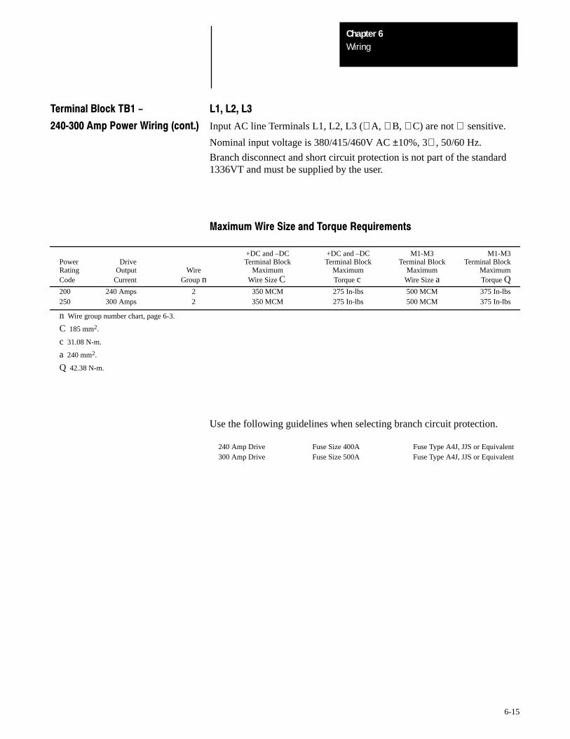
WiringChapter 6
6-15
Terminal Block TB1 - L1, L2, L3
240300Amp Power Wiring (cont.) Input AC line Terminals L1, L2, L3 (∅ A, ∅ B, ∅ C) are not ∅ sensitive.
Nominal input voltage is 380/415/460V AC ±10%, 3∅ , 50/60 Hz.
Branch disconnect and short circuit protection is not part of the standard1336VT and must be supplied by the user.
Maximum Wire Size and Torque Requirements
+DC and –DC +DC and –DC M1-M3 M1-M3Power Drive Terminal Block Terminal Block Terminal Block Terminal BlockRating Output Wire Maximum Maximum Maximum MaximumCode Current Group n Wire Size C Torque c Wire Size a Torque Q200 240 Amps 2 350 MCM 275 In-lbs 500 MCM 375 In-lbs250 300 Amps 2 350 MCM 275 In-lbs 500 MCM 375 In-lbs
n Wire group number chart, page 6-3.
C 185 mm2.
c 31.08 N-m.
a 240 mm2.
Q 42.38 N-m.
Use the following guidelines when selecting branch circuit protection.
240 Amp Drive Fuse Size 400A Fuse Type A4J, JJS or Equivalent300 Amp Drive Fuse Size 500A Fuse Type A4J, JJS or Equivalent
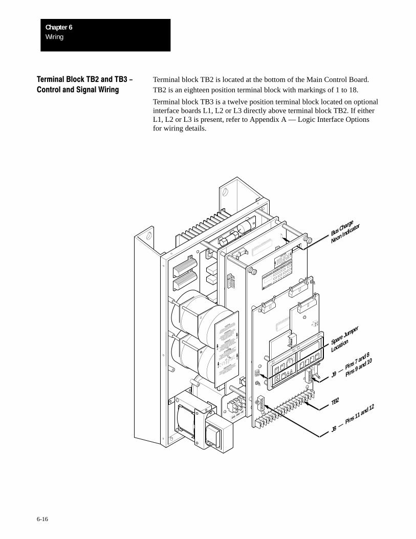
WiringChapter 6
6-16
Terminal Block TB2 and TB3 - Terminal block TB2 is located at the bottom of the Main Control Board.Control and Signal Wiring TB2 is an eighteen position terminal block with markings of 1 to 18.
Terminal block TB3 is a twelve position terminal block located on optionalinterface boards L1, L2 or L3 directly above terminal block TB2. If eitherL1, L2 or L3 is present, refer to Appendix A — Logic Interface Optionsfor wiring details.
TB2
GND GND
M1
+DC –DC
M3M2
L1L2
L3
HAZARDOUS VOLTAGE
ON
CAPACITORS WHEN
NEON
LIGHT IS ON. REMOVE POWER
AND WAIT 60 S
EC. BEFORE
S
ERVICING.
CAUTION
BULLETIN 1336VT ADJUSTABLE FREQUENCY AC DRIVE
12
43
56
78
9 10 11 12 13 14 15 16 17 18
CAUTION
HAZARDOUS VOLTAGE ON CAPACITORS
WHEN NEON LIGHT IS ON. REMOVE POWER
AND WAIT 60 SECONDS BEFORE SERVICING.
ATTENTION
TENSION DANGEREUSE AU NIVEAU DES
CONDENSATEURS QUAND LES NEONS SONT
ALLUMES. COUPER LE COURANT ET
ATTENDRE 60 SECONDES AVANT DE
COMMENCER L'ENTRETIEN.
VORSICHT
AN DEN KONDENSATOREN BESTEHT
HOCHSPANNUNGSGEFAHR, WENN DS NEON-
LICHT AUFLECUDHTET. STROM UNTER-
BRECHEN UND 60 SEK. WARTEN BEVOR
SERVICEARBEITEN DURCHGEFÜHRT WERDEN.
ATTENZIONE
TENSIONE PERICOLOSA SUI CONDENSATORI
QUANDO LA LUCE AL NEON È ACCESA.
TOGLIERE L'ALIMENTAZIONE ED ASPETTARE 60
SECONDI PRIMA DI PRESTARE MANUTENZIONE.
¿¬|– [¥
†[Ÿ Ÿº
|]º]
¬Ÿ[ ¿|]
Ÿº][, <|>/º
¥‡º
~|[º ¥
༠ټ][
<|>/º
¿Ÿº¿|]
|]º]
¬Ÿ[ ¿|]
ټ][, <
|>/º ¥‡º<|>/º
¥‡º
¬Ÿ[ ¿|]
PRECAUCION
AVOLTAJE PERLIGROSO EN LS CAPACITORES
CUANDO LA LUZ DE NEON ESTÉ ENCENDIO.
CORTE LA ENERGIA Y ESPERE 60 DEGUNDOS
ANTES DE DAR SERVICIO.
Freq
PR
Enter
PR
StartJog
Stop
C1
C2➀
➁
SW1
J9 –– Pins 7 and 8
P
ins 9 and 10
J8 –– Pins 11 and 12
Spare Jumper
Location
Bus Charge
Neon Indicator
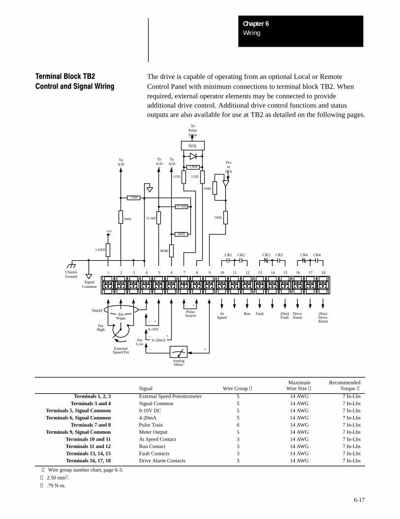
WiringChapter 6
6-17
Terminal Block TB2 The drive is capable of operating from an optional Local or RemoteControl and Signal Wiring Control Panel with minimum connections to terminal block TB2. When
required, external operator elements may be connected to provideadditional drive control. Additional drive control functions and statusoutputs are also available for use at TB2 as detailed on the following pages.
Pot
1 2 3 4 5 6 7 8 9 10 11 12 13 14 15 16 17 18
Wiper
PotHigh
PotLow
ExternalSpeed Pot
+–
+–
+–
+–
CR1 CR2 CR3 CR3 CR4 CR4
ISOL
AnalogMeter
0–10V
PulseSource
4–20mA
At Fault (Not) Drive (Not)RunSpeed Fault Alarm Drive
Alarm
Shield
ToPulseInput
From
D/A
ToA/D
2
ToA/D
3
ToA/D
1
+5VDC
1.4kΩ
215Ω215Ω
100Ω
100Ω
47.5kΩ
200Ω
49.9Ω
53.3kΩ
75kΩ
100Ω
3.42kΩ
ChassisGround
SignalCommon
Maximum RecommendedSignal Wire Group ❶ Wire Size ❷ Torque ❸
Terminals 1, 2, 3 External Speed Potentiometer 5 14 AWG 7 In-LbsTerminals 3 and 4 Signal Common 5 14 AWG 7 In-Lbs
Terminals 5, Signal Common 0-10V DC 5 14 AWG 7 In-LbsTerminals 6, Signal Common 4-20mA 5 14 AWG 7 In-Lbs
Terminals 7 and 8 Pulse Train 6 14 AWG 7 In-LbsTerminals 9, Signal Common Meter Output 5 14 AWG 7 In-Lbs
Terminals 10 and 11 At Speed Contact 3 14 AWG 7 In-LbsTerminals 11 and 12 Run Contact 3 14 AWG 7 In-LbsTerminals 13, 14, 15 Fault Contacts 3 14 AWG 7 In-LbsTerminals 16, 17, 18 Drive Alarm Contacts 3 14 AWG 7 In-Lbs
❶ Wire group number chart, page 6-3.
❷ 2.50 mm2.
❸ .79 N-m.
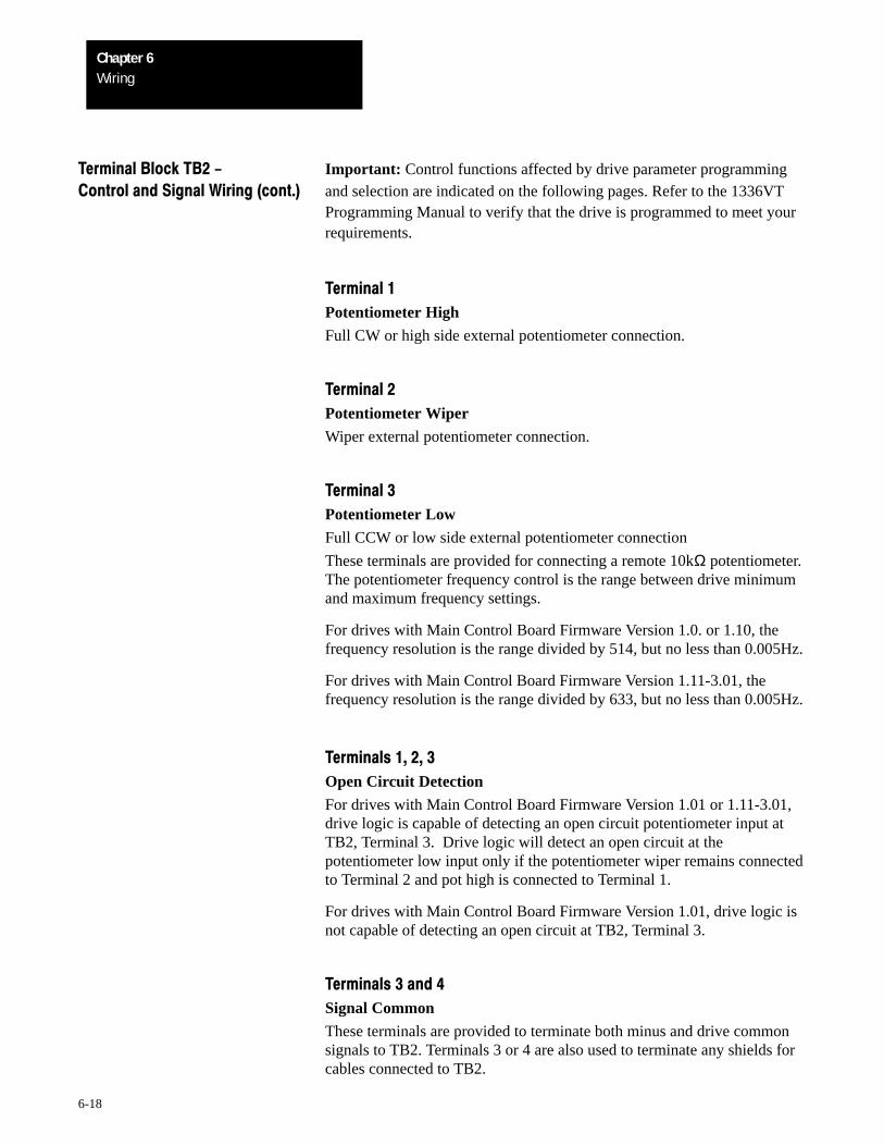
WiringChapter 6
6-18
Terminal Block TB2 - Important: Control functions affected by drive parameter programmingControl and Signal Wiring (cont.) and selection are indicated on the following pages. Refer to the 1336VT
Programming Manual to verify that the drive is programmed to meet yourrequirements.
Terminal 1
Potentiometer High
Full CW or high side external potentiometer connection.
Terminal 2
Potentiometer Wiper
Wiper external potentiometer connection.
Terminal 3
Potentiometer Low
Full CCW or low side external potentiometer connection
These terminals are provided for connecting a remote 10kΩ potentiometer.The potentiometer frequency control is the range between drive minimumand maximum frequency settings.
For drives with Main Control Board Firmware Version 1.0. or 1.10, thefrequency resolution is the range divided by 514, but no less than 0.005Hz.
For drives with Main Control Board Firmware Version 1.11-3.01, thefrequency resolution is the range divided by 633, but no less than 0.005Hz.
Terminals 1, 2, 3
Open Circuit Detection
For drives with Main Control Board Firmware Version 1.01 or 1.11-3.01,drive logic is capable of detecting an open circuit potentiometer input atTB2, Terminal 3. Drive logic will detect an open circuit at thepotentiometer low input only if the potentiometer wiper remains connectedto Terminal 2 and pot high is connected to Terminal 1.
For drives with Main Control Board Firmware Version 1.01, drive logic isnot capable of detecting an open circuit at TB2, Terminal 3.
Terminals 3 and 4
Signal Common
These terminals are provided to terminate both minus and drive commonsignals to TB2. Terminals 3 or 4 are also used to terminate any shields forcables connected to TB2.
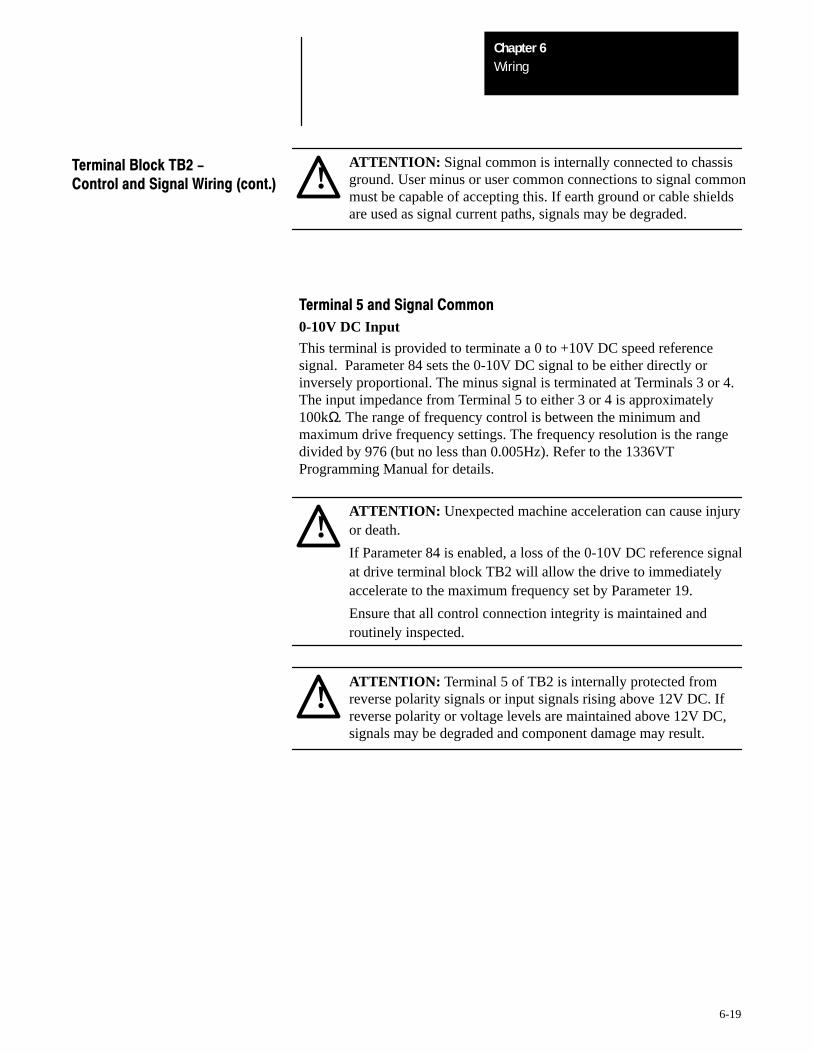
WiringChapter 6
6-19
!ATTENTION: Signal common is internally connected to chassisground. User minus or user common connections to signal commonmust be capable of accepting this. If earth ground or cable shieldsare used as signal current paths, signals may be degraded.
Terminal Block TB2 -Control and Signal Wiring (cont.)
Terminal 5 and Signal Common
0-10V DC Input
This terminal is provided to terminate a 0 to +10V DC speed referencesignal. Parameter 84 sets the 0-10V DC signal to be either directly orinversely proportional. The minus signal is terminated at Terminals 3 or 4.The input impedance from Terminal 5 to either 3 or 4 is approximately100kΩ. The range of frequency control is between the minimum andmaximum drive frequency settings. The frequency resolution is the rangedivided by 976 (but no less than 0.005Hz). Refer to the 1336VTProgramming Manual for details.
!ATTENTION: Unexpected machine acceleration can cause injuryor death.
If Parameter 84 is enabled, a loss of the 0-10V DC reference signalat drive terminal block TB2 will allow the drive to immediatelyaccelerate to the maximum frequency set by Parameter 19.
Ensure that all control connection integrity is maintained androutinely inspected.
!ATTENTION: Terminal 5 of TB2 is internally protected fromreverse polarity signals or input signals rising above 12V DC. Ifreverse polarity or voltage levels are maintained above 12V DC,signals may be degraded and component damage may result.
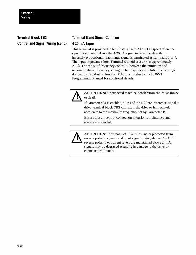
WiringChapter 6
6-20
Terminal Block TB2 - Terminal 6 and Signal Common
Control and Signal Wiring (cont.) 4-20 mA Input
This terminal is provided to terminate a +4 to 20mA DC speed referencesignal. Parameter 84 sets the 4-20mA signal to be either directly orinversely proportional. The minus signal is terminated at Terminals 3 or 4.The input impedance from Terminal 6 to either 3 or 4 is approximately250Ω. The range of frequency control is between the minimum andmaximum drive frequency settings. The frequency resolution is the rangedivided by 726 (but no less than 0.005Hz). Refer to the 1336VTProgramming Manual for additional details.
!ATTENTION: Unexpected machine acceleration can cause injuryor death.
If Parameter 84 is enabled, a loss of the 4-20mA reference signal atdrive terminal block TB2 will allow the drive to immediatelyaccelerate to the maximum frequency set by Parameter 19.
Ensure that all control connection integrity is maintained androutinely inspected.
!ATTENTION: Terminal 6 of TB2 is internally protected fromreverse polarity signals and input signals rising above 24mA. Ifreverse polarity or current levels are maintained above 24mA,signals may be degraded resulting in damage to the drive orconnected equipment.
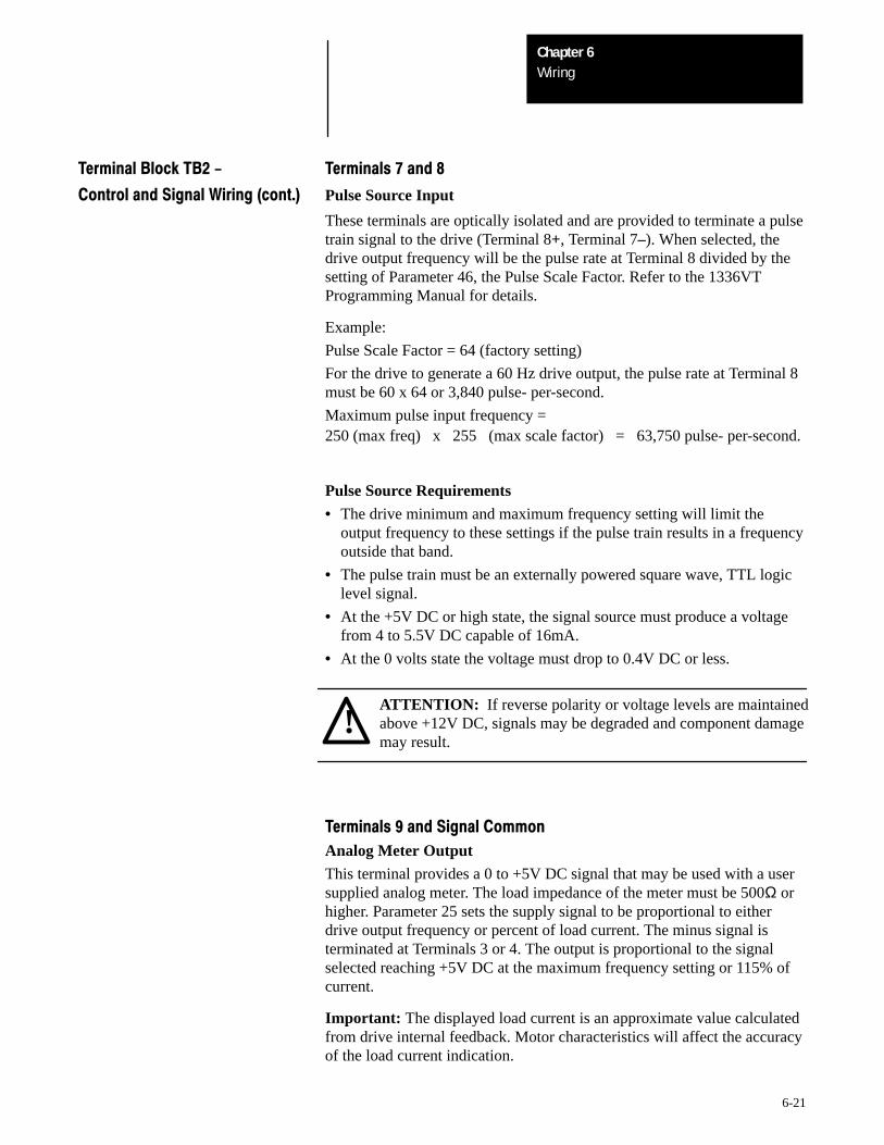
WiringChapter 6
6-21
Terminal Block TB2 - Terminals 7 and 8
Control and Signal Wiring (cont.) Pulse Source Input
These terminals are optically isolated and are provided to terminate a pulsetrain signal to the drive (Terminal 8+, Terminal 7–). When selected, thedrive output frequency will be the pulse rate at Terminal 8 divided by thesetting of Parameter 46, the Pulse Scale Factor. Refer to the 1336VTProgramming Manual for details.
Example:
Pulse Scale Factor = 64 (factory setting)
For the drive to generate a 60 Hz drive output, the pulse rate at Terminal 8must be 60 x 64 or 3,840 pulse- per-second.
Maximum pulse input frequency =250 (max freq) x 255 (max scale factor) = 63,750 pulse- per-second.
Pulse Source Requirements
• The drive minimum and maximum frequency setting will limit theoutput frequency to these settings if the pulse train results in a frequencyoutside that band.
• The pulse train must be an externally powered square wave, TTL logiclevel signal.
• At the +5V DC or high state, the signal source must produce a voltagefrom 4 to 5.5V DC capable of 16mA.
• At the 0 volts state the voltage must drop to 0.4V DC or less.
!ATTENTION: If reverse polarity or voltage levels are maintainedabove +12V DC, signals may be degraded and component damagemay result.
Terminals 9 and Signal Common
Analog Meter Output
This terminal provides a 0 to +5V DC signal that may be used with a usersupplied analog meter. The load impedance of the meter must be 500Ω orhigher. Parameter 25 sets the supply signal to be proportional to eitherdrive output frequency or percent of load current. The minus signal isterminated at Terminals 3 or 4. The output is proportional to the signalselected reaching +5V DC at the maximum frequency setting or 115% ofcurrent.
Important: The displayed load current is an approximate value calculatedfrom drive internal feedback. Motor characteristics will affect the accuracyof the load current indication.
WiringChapter 6
6-22
Terminal Block TB2 - Terminals 10 and 11
Control and Signal Wiring (cont.) At Speed
These terminals allow an internal drive supplied at speed contact to be usedin external circuits. Parameter 77 allows the at speed contact to beprogrammed to change state within ±0.5% of maximum speed for one oftwo conditions –– When the drive reaches command speed or when thedrive reaches a programmed set point reference frequency. The contact isisolated from logic and other drive circuitry.
Resistive rating: 120V AC or 30V DC, 5.0 amps
Inductive rating: 120V AC or 30V DC, 2.0 amps
Terminals 11 and 12
Run
These terminals allow an internal drive supplied run contact to be used inexternal circuits. The N.O. contact closes when the drive is running andopens when the drive is stopped and not generating any output to theconnected load. The contact is isolated from logic and other drive circuitry.
Resistive rating: 120V AC or 30V DC, 5.0 amps
Inductive rating: 120 V AC or 30V DC, 2.0 amps
Terminals 13, 14, 15
Fault
These terminals allow internal drive supplied fault contacts to be used inexternal circuits. The contacts are shown in the de-energized (faulted) state.When the drive is powered up and no fault is present, the contacts willchange state, 13 to 14 will open, 14 to 15 will close.
Both the N.C. and N.O. contacts will change state(13 to 14 will close, 14 to 15 will open) when the drive has detected a Faultor power is removed from the drive.
Resistive rating: 120V AC or 30V DC, 5.0 amps
Inductive rating: 120 V AC or 30V DC, 2.0 amps
WiringChapter 6
6-23
Terminal Block TB2 - Terminals 16, 17, 18
Control and Signal Wiring (cont.) Drive Alarm
These terminals allow internal drive supplied alarm contacts to be used inexternal circuits. The contacts are shown in the de-energized (alarm) state.When the drive is powered up and no alarm is present, the contacts willchange state: 16 to 17 will open, 17 to 18 will close.
Both the N.C. and N.O. contacts will change state(16 to 17 will close, 17 to 18 will open) when the drive has detected analarm or power is removed from the drive.
Resistive rating: 120V AC or 30V DC, 5.0 amps
Inductive rating: 120 V AC or 30V DC, 2.0 amps
Drive Alarm Conditions are:
• Drive output current is above 115% of rated current.
• Drive output current is above the MOPC limit set by Parameter 36.
• Bus voltage is above 110% of nominal input voltage. A continued rise inbus voltage may result in Parameter 11 Decel Frequency Hold affectingthe decel ramp, or fault F05 Bus Overvoltage.
• Bus voltage is below 85% of nominal input voltage.
• Precharge not complete.
• Parameter 14 Auto Restart is active.
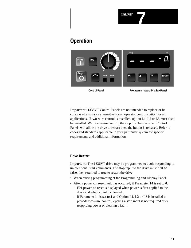
7Chapter
7-1
Operation
Start Jog
Stop
Freq PR
EnterPR
Control Panel Programming and Display Panel
Important: 1336VT Control Panels are not intended to replace or beconsidered a suitable alternative for an operator control station for allapplications. If two-wire control is installed, option L1, L2 or L3 must alsobe installed. With two-wire control, the stop pushbutton on all ControlPanels will allow the drive to restart once the button is released. Refer tocodes and standards applicable to your particular system for specificrequirements and additional information.
Drive Restart
Important: The 1336VT drive may be programmed to avoid responding tounintentional start commands. The stop input to the drive must first befalse, then returned to true to restart the drive:
• When exiting programming at the Programming and Display Panel.
• After a power-on reset fault has occurred, if Parameter 14 is set to 0.– F01 power-on reset is displayed when power is first applied to the
drive and when a fault is cleared.– If Parameter 14 is set to 1 and Option L1, L2 or L3 is installed to
provide two-wire control, cycling a stop input is not required afterreapplying power or clearing a fault.
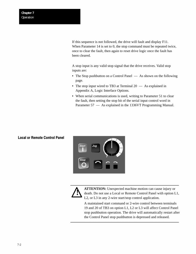
OperationChapter 7
7-2
If this sequence is not followed, the drive will fault and display F11.When Parameter 14 is set to 0, the stop command must be repeated twice,once to clear the fault, then again to reset drive logic once the fault hasbeen cleared.
A stop input is any valid stop signal that the drive receives. Valid stopinputs are:
• The Stop pushbutton on a Control Panel –– As shown on the followingpage.
• The stop input wired to TB3 at Terminal 20 –– As explained inAppendix A, Logic Interface Options.
• When serial communications is used, writing to Parameter 51 to clearthe fault, then setting the stop bit of the serial input control word inParameter 57 –– As explained in the 1336VT Programming Manual.
Local or Remote Control Panel
Start Jog
Stop
!ATTENTION: Unexpected machine motion can cause injury ordeath. Do not use a Local or Remote Control Panel with option L1,L2, or L3 in any 2-wire start/stop control application.
A maintained start command or 2-wire control between terminals19 and 20 of TB3 on option L1, L2 or L3 will affect Control Panelstop pushbutton operation. The drive will automatically restart afterthe Control Panel stop pushbutton is depressed and released.
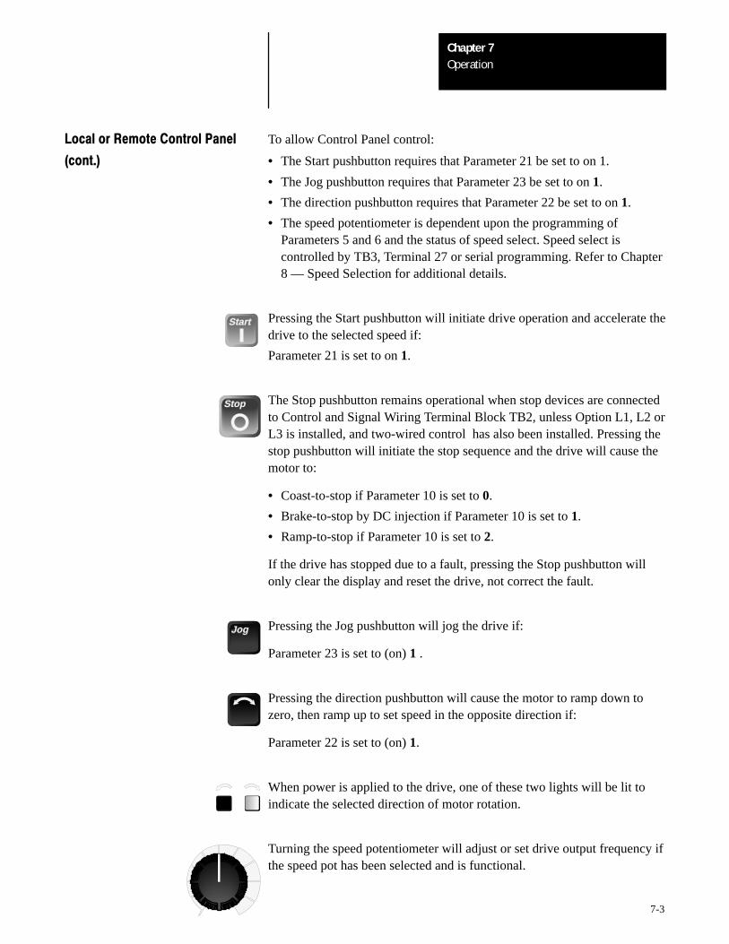
OperationChapter 7
7-3
Local or Remote Control Panel To allow Control Panel control:
(cont.) • The Start pushbutton requires that Parameter 21 be set to on 1.
• The Jog pushbutton requires that Parameter 23 be set to on 1.
• The direction pushbutton requires that Parameter 22 be set to on 1.
• The speed potentiometer is dependent upon the programming ofParameters 5 and 6 and the status of speed select. Speed select iscontrolled by TB3, Terminal 27 or serial programming. Refer to Chapter8 — Speed Selection for additional details.
Start Pressing the Start pushbutton will initiate drive operation and accelerate thedrive to the selected speed if:
Parameter 21 is set to on 1.
Stop The Stop pushbutton remains operational when stop devices are connectedto Control and Signal Wiring Terminal Block TB2, unless Option L1, L2 orL3 is installed, and two-wired control has also been installed. Pressing thestop pushbutton will initiate the stop sequence and the drive will cause themotor to:
• Coast-to-stop if Parameter 10 is set to 0.
• Brake-to-stop by DC injection if Parameter 10 is set to 1.
• Ramp-to-stop if Parameter 10 is set to 2.
If the drive has stopped due to a fault, pressing the Stop pushbutton willonly clear the display and reset the drive, not correct the fault.
Jog Pressing the Jog pushbutton will jog the drive if:
Parameter 23 is set to (on) 1 .
Pressing the direction pushbutton will cause the motor to ramp down tozero, then ramp up to set speed in the opposite direction if:
Parameter 22 is set to (on) 1.
When power is applied to the drive, one of these two lights will be lit toindicate the selected direction of motor rotation.
Turning the speed potentiometer will adjust or set drive output frequency ifthe speed pot has been selected and is functional.
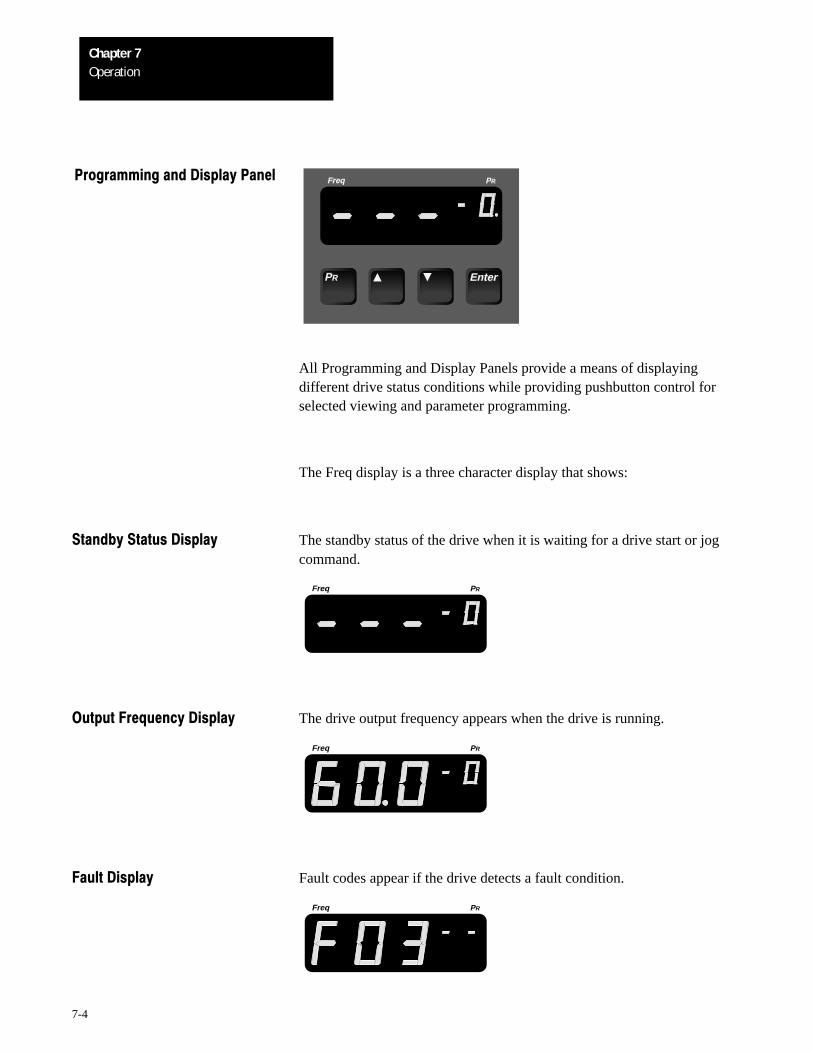
OperationChapter 7
7-4
Programming and Display Panel Freq PR
EnterPR
All Programming and Display Panels provide a means of displayingdifferent drive status conditions while providing pushbutton control forselected viewing and parameter programming.
The Freq display is a three character display that shows:
Standby Status Display The standby status of the drive when it is waiting for a drive start or jogcommand.
Freq PR
Output Frequency Display The drive output frequency appears when the drive is running.
Freq PR
Fault Display Fault codes appear if the drive detects a fault condition.
Freq PR
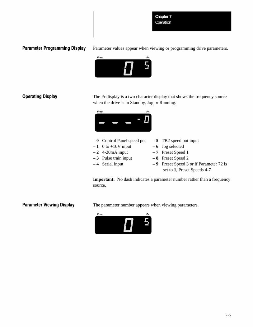
OperationChapter 7
7-5
Parameter Programming Display Parameter values appear when viewing or programming drive parameters.
Freq PR
Operating Display The Pr display is a two character display that shows the frequency sourcewhen the drive is in Standby, Jog or Running.
Freq PR
– 0 Control Panel speed pot – 5 TB2 speed pot input– 1 0 to +10V input – 6 Jog selected– 2 4-20mA input – 7 Preset Speed 1– 3 Pulse train input – 8 Preset Speed 2– 4 Serial input – 9 Preset Speed 3 or if Parameter 72 is
set to 1, Preset Speeds 4-7
Important: No dash indicates a parameter number rather than a frequencysource.
Parameter Viewing Display The parameter number appears when viewing parameters.
Freq PR
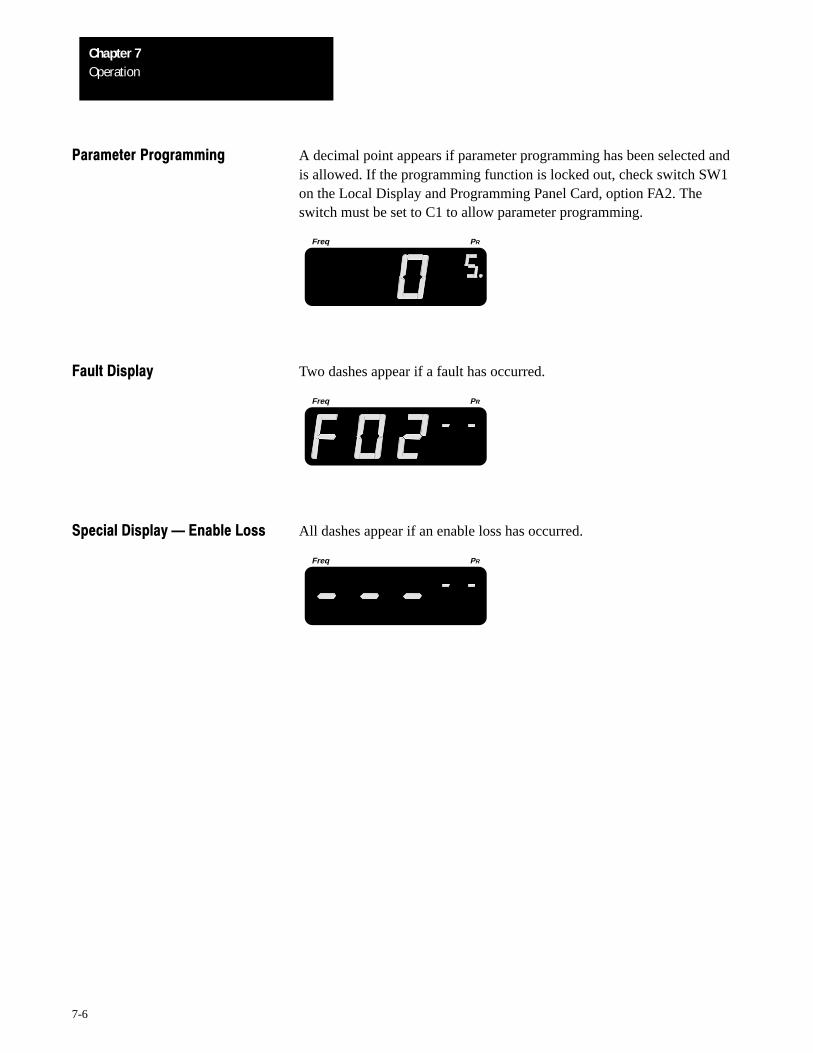
OperationChapter 7
7-6
Parameter Programming A decimal point appears if parameter programming has been selected andis allowed. If the programming function is locked out, check switch SW1on the Local Display and Programming Panel Card, option FA2. Theswitch must be set to C1 to allow parameter programming.
Freq PR
Fault Display Two dashes appear if a fault has occurred.
Freq PR
Special Display Enable Loss All dashes appear if an enable loss has occurred.
Freq PR
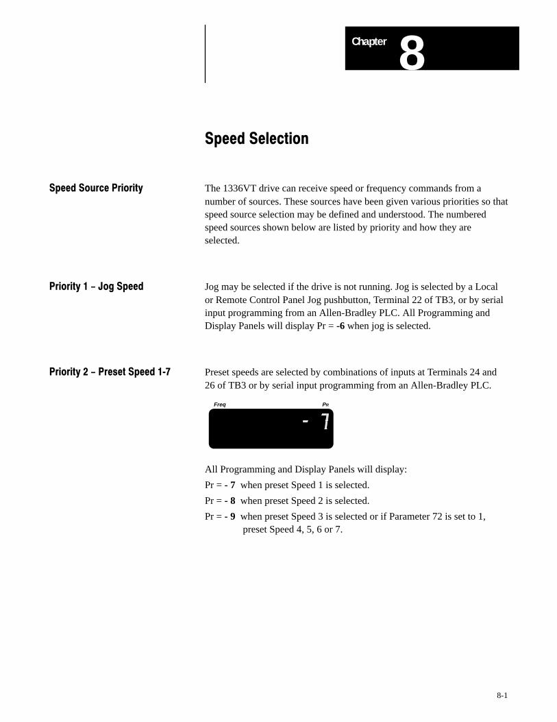
8Chapter
8-1
Speed Selection
Speed Source Priority The 1336VT drive can receive speed or frequency commands from anumber of sources. These sources have been given various priorities so thatspeed source selection may be defined and understood. The numberedspeed sources shown below are listed by priority and how they areselected.
Priority 1 - Jog Speed Jog may be selected if the drive is not running. Jog is selected by a Localor Remote Control Panel Jog pushbutton, Terminal 22 of TB3, or by serialinput programming from an Allen-Bradley PLC. All Programming andDisplay Panels will display Pr = -6 when jog is selected.
Priority 2 - Preset Speed 17 Preset speeds are selected by combinations of inputs at Terminals 24 and26 of TB3 or by serial input programming from an Allen-Bradley PLC.
Freq PR
All Programming and Display Panels will display:
Pr = - 7 when preset Speed 1 is selected.
Pr = - 8 when preset Speed 2 is selected.
Pr = - 9 when preset Speed 3 is selected or if Parameter 72 is set to 1, preset Speed 4, 5, 6 or 7.
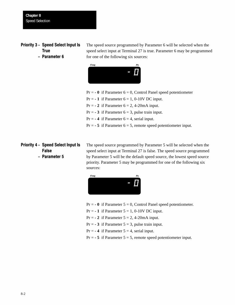
Speed SelectionChapter 8
8-2
Priority 3 - Speed Select Input Is The speed source programmed by Parameter 6 will be selected when theTrue speed select input at Terminal 27 is true. Parameter 6 may be programmed
- Parameter 6 for one of the following six sources:
Freq PR
Pr = - 0 if Parameter 6 = 0, Control Panel speed potentiometer
Pr = - 1 if Parameter 6 = 1, 0-10V DC input.
Pr = - 2 if Parameter 6 = 2, 4-20mA input.
Pr = - 3 if Parameter 6 = 3, pulse train input.
Pr = - 4 if Parameter 6 = 4, serial input.
Pr = - 5 if Parameter 6 = 5, remote speed potentiometer input.
Priority 4 - Speed Select Input Is The speed source programmed by Parameter 5 will be selected when theFalse speed select input at Terminal 27 is false. The speed source programmed
- Parameter 5 by Parameter 5 will be the default speed source, the lowest speed sourcepriority. Parameter 5 may be programmed for one of the following sixsources:
Freq PR
Pr = - 0 if Parameter 5 = 0, Control Panel speed potentiometer.
Pr = - 1 if Parameter 5 = 1, 0-10V DC input.
Pr = - 2 if Parameter 5 = 2, 4-20mA input.
Pr = - 3 if Parameter 5 = 3, pulse train input.
Pr = - 4 if Parameter 5 = 4, serial input.
Pr = - 5 if Parameter 5 = 5, remote speed potentiometer input.
9Chapter
9-1
Startup
The following startup procedure is written for users who have a ControlPanel and a Programming & Display Panel installed and who are not usinga 2-wire drive control scheme. For users without a Control Panel and aProgramming & Display Panel, respective external commands and signalsmust be substituted to simulate their operation.
!ATTENTION: Power must be applied to the drive with the coverremoved to perform certain startup procedures. Voltages on manycomponents are at incoming line potential or bus voltage. To avoidelectric shock hazard or damage to equipment, do not touch anydrive component other than those specified in the startupprocedure.
!ATTENTION: Become familiar with the equipment and readthrough the wiring, speed selection and adjustment sections beforeattempting to perform the startup procedures. Adjustments may berequired to meet specific load characteristics or operatorpreference.
Exercise extreme care when performing any task on the drive.Failure to do so may result in electric shock or equipment damage.
As shown on page 6-16, a bus charge neon indicator at the top ofthe 1336VT has been provided to provide visual indication that busvoltage is present. Bus voltage may be verified by using avoltmeter and measuring the voltage between +DC and –DC onterminal block TB1. Do not attempt to service the drive until theneon indicator has extinguished and the bus voltage has dischargedto zero volts.
Important:
1. Power must be applied to the drive when viewing or changing 1336VTparameters. Previous programming may effect the drive status whenpower is applied in Step 7.
2. If option L1, L2 or L3 is installed, remote start circuits may beconnected to TB3 on the Interface Board. Confirm that all circuits are ina de-energized state before applying power.
3. If option L1, L2 or L3 is installed, user supplied voltages may exist atTB3 on the interface board even when power is not applied to the drive.
4. If you cannot complete a procedure, refer to Chapter 10 — Fault Codesimmediately. Do not proceed. Determine the cause of the problem andcorrect the problem first, then return to the startup procedure.
StartupChapter 9
9-2
Initial Operation Step 1
- Motor Disconnected Verify that AC line power at the disconnect device is within the rated valueof the drive. Drive nameplate and alternate voltage ratings are listed inChapter 2 — Drive and Option Identification.
Step 2
Remove and lock out all incoming power to the drive. Remove the drivecover and disconnect motor leads from drive terminals M1, M2 and M3.
Step 3
If one of the following optional interface boards is installed:
1336-MOD-L11336-MOD-L21336-MOD-L3
• Verify that interface input connections to the board match the voltagerating of the board.
• Verify that enable and auxiliary interlock inputs are provided.
Step 4
If option L1, L2 or L3 is not installed, verify that the three spare jumpersprovided with the drive are installed correctly at connectors J8 and J9.
Control Board connector J8 –– Pins 11 and 12 jumpered
Control Board connector J9 –– Pins 7 and 8 jumperedPins 9 and 10 jumpered
Step 5
Confirm that all other optional inputs are connected to their correctterminals and are secure.
Step 6
Replace the drive cover and tighten all thumbscrews.
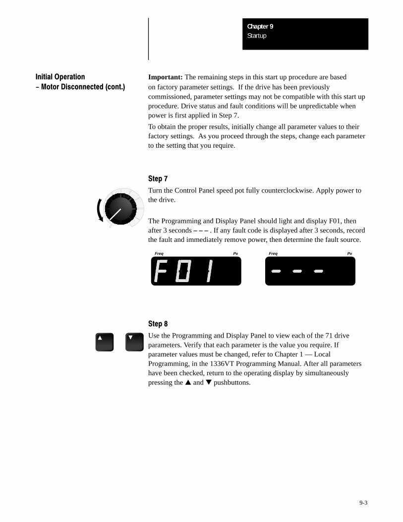
StartupChapter 9
9-3
Initial Operation Important: The remaining steps in this start up procedure are based- Motor Disconnected (cont.) on factory parameter settings. If the drive has been previously
commissioned, parameter settings may not be compatible with this start upprocedure. Drive status and fault conditions will be unpredictable whenpower is first applied in Step 7.
To obtain the proper results, initially change all parameter values to theirfactory settings. As you proceed through the steps, change each parameterto the setting that you require.
Step 7
Turn the Control Panel speed pot fully counterclockwise. Apply power tothe drive.
The Programming and Display Panel should light and display F01, thenafter 3 seconds – – – . If any fault code is displayed after 3 seconds, recordthe fault and immediately remove power, then determine the fault source.
Freq PRFreq PR
Step 8
Use the Programming and Display Panel to view each of the 71 driveparameters. Verify that each parameter is the value you require. Ifparameter values must be changed, refer to Chapter 1 — LocalProgramming, in the 1336VT Programming Manual. After all parametershave been checked, return to the operating display by simultaneouslypressing the and pushbuttons.
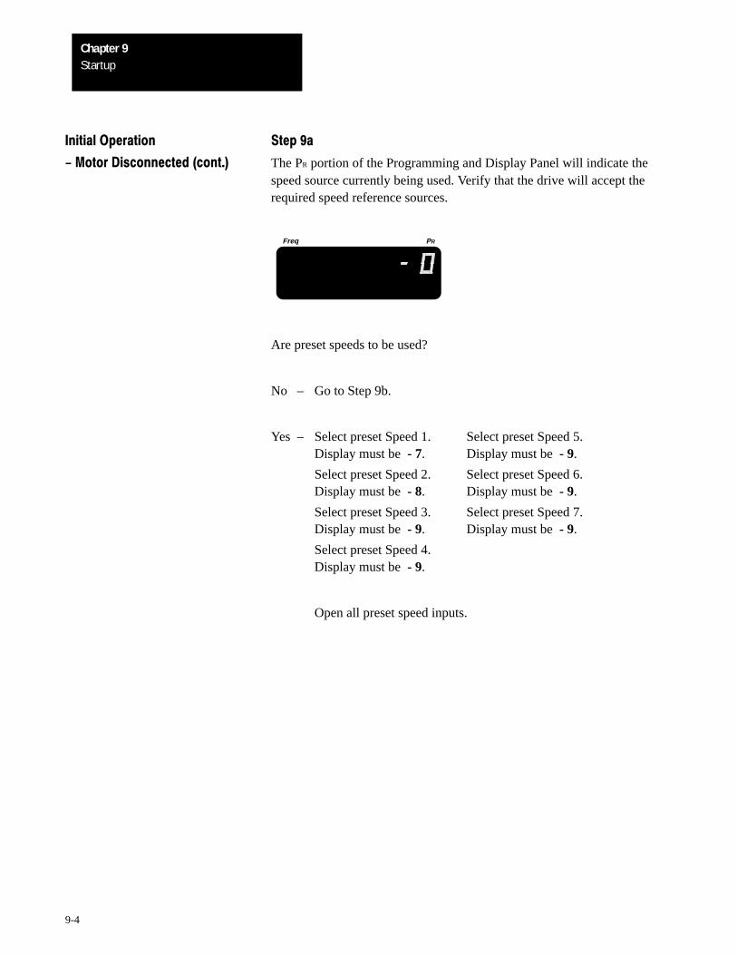
StartupChapter 9
9-4
Initial Operation Step 9a
- Motor Disconnected (cont.) The PR portion of the Programming and Display Panel will indicate thespeed source currently being used. Verify that the drive will accept therequired speed reference sources.
Freq PR
Are preset speeds to be used?
No – Go to Step 9b.
Yes – Select preset Speed 1. Select preset Speed 5.Display must be - 7. Display must be - 9.
Select preset Speed 2. Select preset Speed 6.Display must be - 8. Display must be - 9.
Select preset Speed 3. Select preset Speed 7.Display must be - 9. Display must be - 9.
Select preset Speed 4.Display must be - 9.
Open all preset speed inputs.
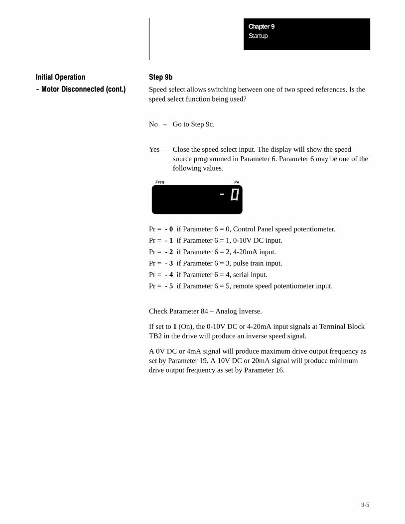
StartupChapter 9
9-5
Initial Operation Step 9b
- Motor Disconnected (cont.) Speed select allows switching between one of two speed references. Is thespeed select function being used?
No – Go to Step 9c.
Yes – Close the speed select input. The display will show the speedsource programmed in Parameter 6. Parameter 6 may be one of thefollowing values.
Freq PR
Pr = - 0 if Parameter 6 = 0, Control Panel speed potentiometer.
Pr = - 1 if Parameter 6 = 1, 0-10V DC input.
Pr = - 2 if Parameter 6 = 2, 4-20mA input.
Pr = - 3 if Parameter 6 = 3, pulse train input.
Pr = - 4 if Parameter 6 = 4, serial input.
Pr = - 5 if Parameter 6 = 5, remote speed potentiometer input.
Check Parameter 84 – Analog Inverse.
If set to 1 (On), the 0-10V DC or 4-20mA input signals at Terminal BlockTB2 in the drive will produce an inverse speed signal.
A 0V DC or 4mA signal will produce maximum drive output frequency asset by Parameter 19. A 10V DC or 20mA signal will produce minimumdrive output frequency as set by Parameter 16.
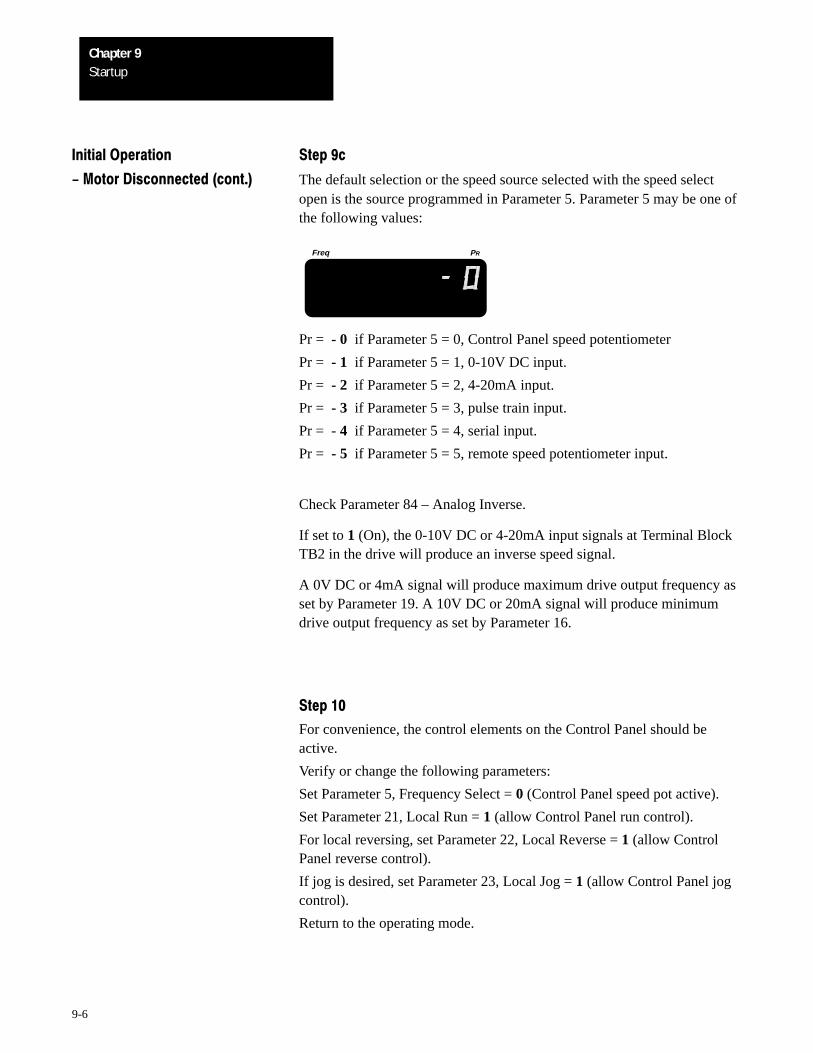
StartupChapter 9
9-6
Initial Operation Step 9c
- Motor Disconnected (cont.) The default selection or the speed source selected with the speed selectopen is the source programmed in Parameter 5. Parameter 5 may be one ofthe following values:
Freq PR
Pr = - 0 if Parameter 5 = 0, Control Panel speed potentiometer
Pr = - 1 if Parameter 5 = 1, 0-10V DC input.
Pr = - 2 if Parameter 5 = 2, 4-20mA input.
Pr = - 3 if Parameter 5 = 3, pulse train input.
Pr = - 4 if Parameter 5 = 4, serial input.
Pr = - 5 if Parameter 5 = 5, remote speed potentiometer input.
Check Parameter 84 – Analog Inverse.
If set to 1 (On), the 0-10V DC or 4-20mA input signals at Terminal BlockTB2 in the drive will produce an inverse speed signal.
A 0V DC or 4mA signal will produce maximum drive output frequency asset by Parameter 19. A 10V DC or 20mA signal will produce minimumdrive output frequency as set by Parameter 16.
Step 10
For convenience, the control elements on the Control Panel should beactive.
Verify or change the following parameters:
Set Parameter 5, Frequency Select = 0 (Control Panel speed pot active).
Set Parameter 21, Local Run = 1 (allow Control Panel run control).
For local reversing, set Parameter 22, Local Reverse = 1 (allow ControlPanel reverse control).
If jog is desired, set Parameter 23, Local Jog = 1 (allow Control Panel jogcontrol).
Return to the operating mode.
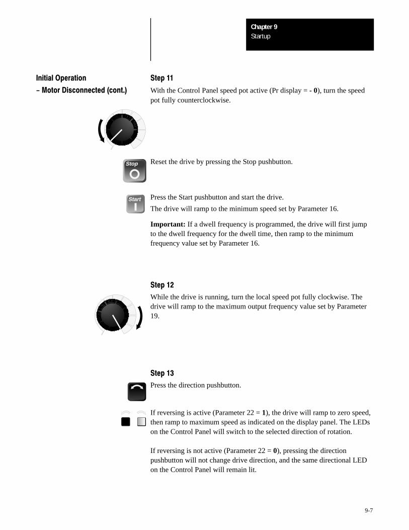
StartupChapter 9
9-7
Initial Operation Step 11
- Motor Disconnected (cont.) With the Control Panel speed pot active (Pr display = - 0), turn the speedpot fully counterclockwise.
Stop Reset the drive by pressing the Stop pushbutton.
Start Press the Start pushbutton and start the drive.
The drive will ramp to the minimum speed set by Parameter 16.
Important: If a dwell frequency is programmed, the drive will first jumpto the dwell frequency for the dwell time, then ramp to the minimumfrequency value set by Parameter 16.
Step 12
While the drive is running, turn the local speed pot fully clockwise. Thedrive will ramp to the maximum output frequency value set by Parameter19.
Step 13
Press the direction pushbutton.
If reversing is active (Parameter 22 = 1), the drive will ramp to zero speed,then ramp to maximum speed as indicated on the display panel. The LEDson the Control Panel will switch to the selected direction of rotation.
If reversing is not active (Parameter 22 = 0), pressing the directionpushbutton will not change drive direction, and the same directional LEDon the Control Panel will remain lit.
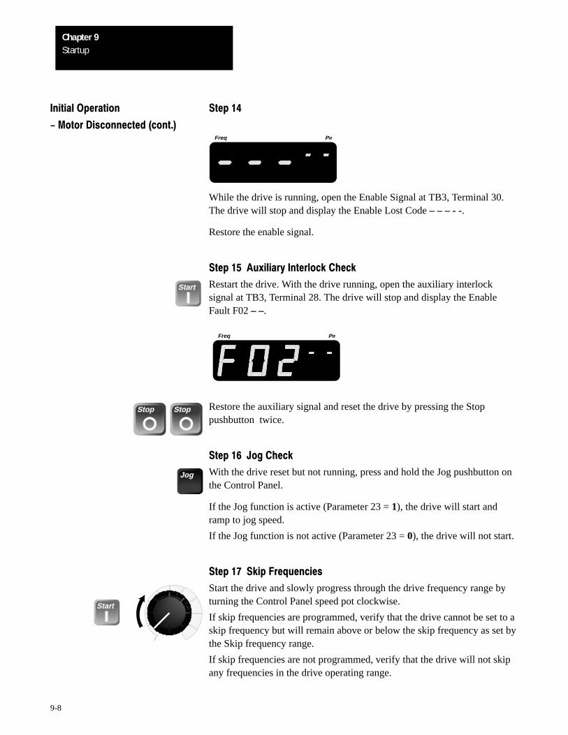
StartupChapter 9
9-8
Initial Operation Step 14
- Motor Disconnected (cont.)Freq PR
While the drive is running, open the Enable Signal at TB3, Terminal 30.The drive will stop and display the Enable Lost Code – – – - -.
Restore the enable signal.
Step 15Auxiliary Interlock Check
Start Restart the drive. With the drive running, open the auxiliary interlocksignal at TB3, Terminal 28. The drive will stop and display the EnableFault F02 – –.
Freq PR
Stop Stop Restore the auxiliary signal and reset the drive by pressing the Stoppushbutton twice.
Step 16Jog Check
Jog With the drive reset but not running, press and hold the Jog pushbutton onthe Control Panel.
If the Jog function is active (Parameter 23 = 1), the drive will start andramp to jog speed.
If the Jog function is not active (Parameter 23 = 0), the drive will not start.
Step 17Skip Frequencies
Start
Start the drive and slowly progress through the drive frequency range byturning the Control Panel speed pot clockwise.
If skip frequencies are programmed, verify that the drive cannot be set to askip frequency but will remain above or below the skip frequency as set bythe Skip frequency range.
If skip frequencies are not programmed, verify that the drive will not skipany frequencies in the drive operating range.
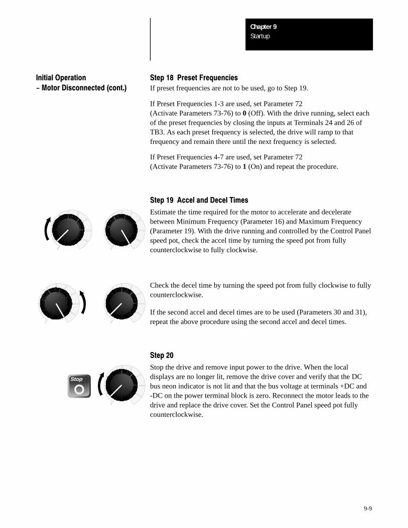
StartupChapter 9
9-9
Initial Operation Step 18Preset Frequencies
- Motor Disconnected (cont.) If preset frequencies are not to be used, go to Step 19.
If Preset Frequencies 1-3 are used, set Parameter 72(Activate Parameters 73-76) to 0 (Off). With the drive running, select eachof the preset frequencies by closing the inputs at Terminals 24 and 26 ofTB3. As each preset frequency is selected, the drive will ramp to thatfrequency and remain there until the next frequency is selected.
If Preset Frequencies 4-7 are used, set Parameter 72(Activate Parameters 73-76) to 1 (On) and repeat the procedure.
Step 19Accel and Decel Times
Estimate the time required for the motor to accelerate and deceleratebetween Minimum Frequency (Parameter 16) and Maximum Frequency(Parameter 19). With the drive running and controlled by the Control Panelspeed pot, check the accel time by turning the speed pot from fullycounterclockwise to fully clockwise.
Check the decel time by turning the speed pot from fully clockwise to fullycounterclockwise.
If the second accel and decel times are to be used (Parameters 30 and 31),repeat the above procedure using the second accel and decel times.
Step 20
Stop
Stop the drive and remove input power to the drive. When the localdisplays are no longer lit, remove the drive cover and verify that the DCbus neon indicator is not lit and that the bus voltage at terminals +DC and-DC on the power terminal block is zero. Reconnect the motor leads to thedrive and replace the drive cover. Set the Control Panel speed pot fullycounterclockwise.
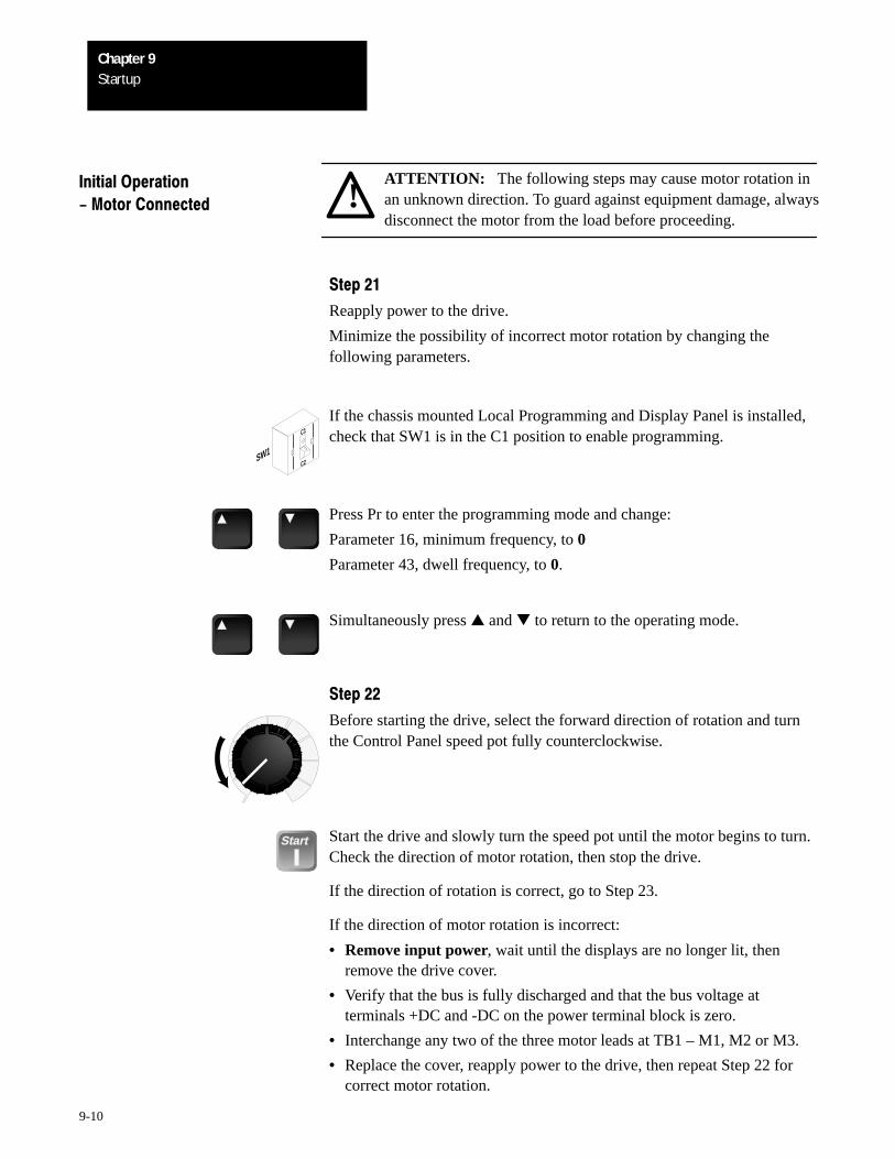
StartupChapter 9
9-10
!ATTENTION: The following steps may cause motor rotation inan unknown direction. To guard against equipment damage, alwaysdisconnect the motor from the load before proceeding.
Initial Operation
- Motor Connected
Step 21
Reapply power to the drive.
Minimize the possibility of incorrect motor rotation by changing thefollowing parameters.
C1
C2➀
➁
SW1
If the chassis mounted Local Programming and Display Panel is installed,check that SW1 is in the C1 position to enable programming.
Press Pr to enter the programming mode and change:
Parameter 16, minimum frequency, to 0
Parameter 43, dwell frequency, to 0.
Simultaneously press and to return to the operating mode.
Step 22
Before starting the drive, select the forward direction of rotation and turnthe Control Panel speed pot fully counterclockwise.
Start Start the drive and slowly turn the speed pot until the motor begins to turn.Check the direction of motor rotation, then stop the drive.
If the direction of rotation is correct, go to Step 23.
If the direction of motor rotation is incorrect:
• Remove input power, wait until the displays are no longer lit, thenremove the drive cover.
• Verify that the bus is fully discharged and that the bus voltage atterminals +DC and -DC on the power terminal block is zero.
• Interchange any two of the three motor leads at TB1 – M1, M2 or M3.
• Replace the cover, reapply power to the drive, then repeat Step 22 forcorrect motor rotation.
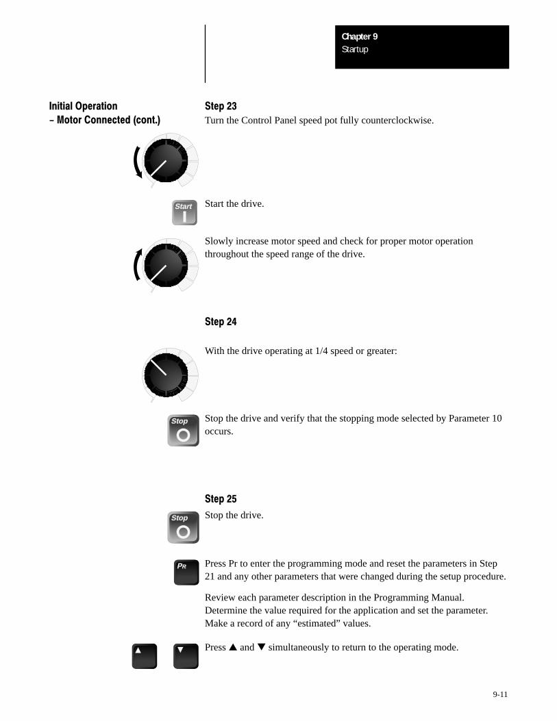
StartupChapter 9
9-11
Initial Operation Step 23
- Motor Connected (cont.) Turn the Control Panel speed pot fully counterclockwise.
Start Start the drive.
Slowly increase motor speed and check for proper motor operationthroughout the speed range of the drive.
Step 24
With the drive operating at 1/4 speed or greater:
Stop Stop the drive and verify that the stopping mode selected by Parameter 10occurs.
Step 25
Stop Stop the drive.
PR Press Pr to enter the programming mode and reset the parameters in Step21 and any other parameters that were changed during the setup procedure.
Review each parameter description in the Programming Manual.Determine the value required for the application and set the parameter.Make a record of any “estimated” values.
Press and simultaneously to return to the operating mode.
StartupChapter 9
9-12
Initial Operation Step 26
- Motor Connected (cont.) If the drive is to receive control signals and data from a programmablecontroller via the MOD-G2 Remote I/O communication option, theprogrammable controller must be tested with the motor disconnected fromthe load.
Prepare all drive control signal interfaces and Remote I/O option forprogrammable controller operation. Refer to Remote I/O InstructionManual.
Reset appropriate drive control parameters 5-50 and 72-86. Particularattention must be given to Parameter 22 – Local Reverse and Parameter 84– Analog Inverse.
Apply power and test the program. Observe drive operation and correct allcommunications, drive operation and equipment malfunction defaultproblems immediately.
After achieving proper operation, record all parameter values in theProgramming Manual.
Step 27
!ATTENTION: To avoid hazards of electrical shock or injuryfrom moving equipment, product or process ingredients:
• Alert all personnel.
• Install all guards.
• Check operation of all safety devices.
• Be prepared to stop the motor immediately.
Disconnect and lock-out all power. Connect the motor to the load.
Before applying power, review the parameter descriptions in theProgramming Manual. Each parameter may have a significant effect onfundamental drive and motor operation regardless of the control methodused.
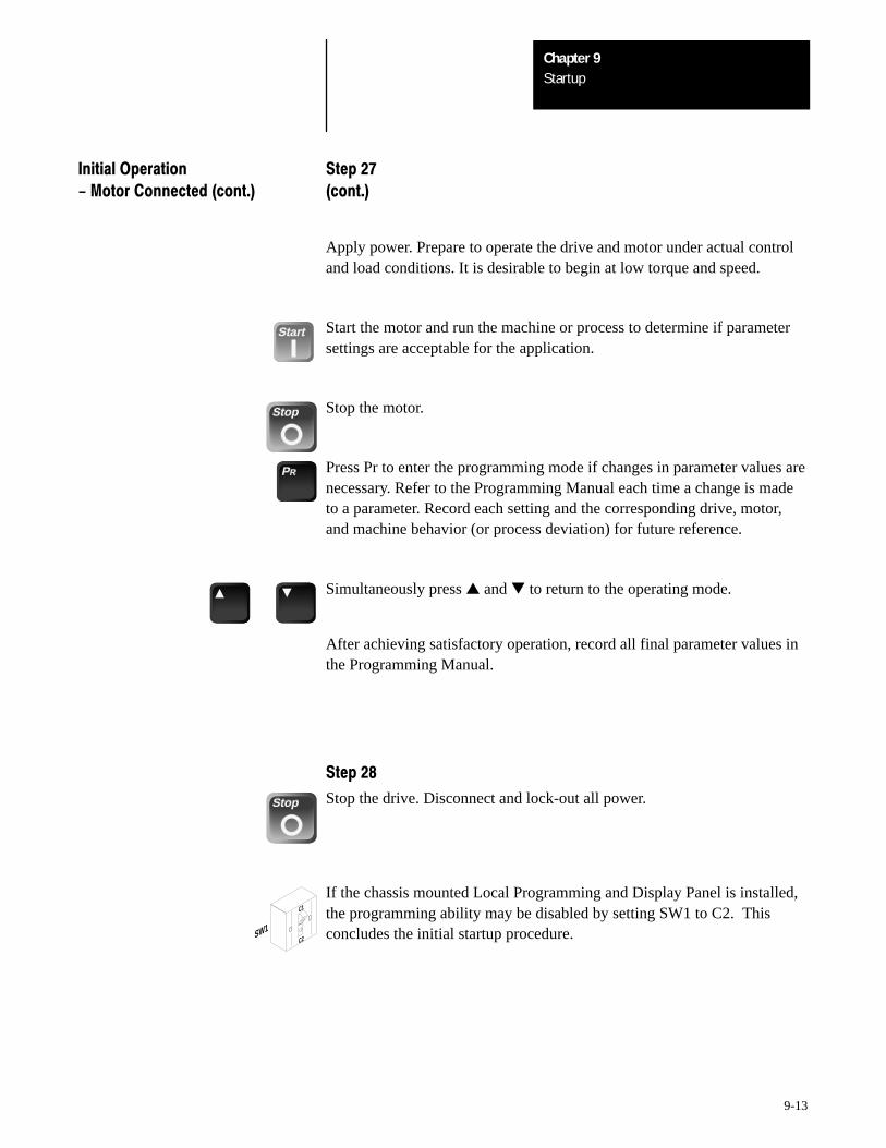
StartupChapter 9
9-13
Initial Operation Step 27
- Motor Connected (cont.) (cont.)
Apply power. Prepare to operate the drive and motor under actual controland load conditions. It is desirable to begin at low torque and speed.
Start Start the motor and run the machine or process to determine if parametersettings are acceptable for the application.
Stop Stop the motor.
PR Press Pr to enter the programming mode if changes in parameter values arenecessary. Refer to the Programming Manual each time a change is madeto a parameter. Record each setting and the corresponding drive, motor,and machine behavior (or process deviation) for future reference.
Simultaneously press and to return to the operating mode.
After achieving satisfactory operation, record all final parameter values inthe Programming Manual.
Step 28
Stop Stop the drive. Disconnect and lock-out all power.
SW1
C1
C2➀
➁
If the chassis mounted Local Programming and Display Panel is installed,the programming ability may be disabled by setting SW1 to C2. Thisconcludes the initial startup procedure.
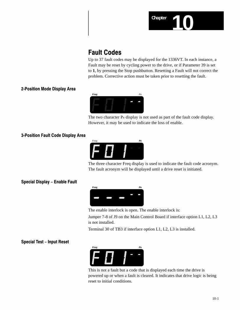
10Chapter
10-1
Fault CodesUp to 37 fault codes may be displayed for the 1336VT. In each instance, aFault may be reset by cycling power to the drive, or if Parameter 39 is setto 1, by pressing the Stop pushbutton. Resetting a Fault will not correct theproblem. Corrective action must be taken prior to resetting the fault.
2Position Mode Display AreaFreq PR
The two character PR display is not used as part of the fault code display.However, it may be used to indicate the loss of enable.
3Position Fault Code Display AreaFreq PR
The three character Freq display is used to indicate the fault code acronym.The fault acronym will be displayed until a drive reset is initiated.
Special Display - Enable FaultFreq PR
The enable interlock is open. The enable interlock is:
Jumper 7-8 of J9 on the Main Control Board if interface option L1, L2, L3is not installed.
Terminal 30 of TB3 if interface option L1, L2, L3 is installed.
Special Test - Input ResetFreq PR
This is not a fault but a code that is displayed each time the drive ispowered up or when a fault is cleared. It indicates that drive logic is beingreset to initial conditions.
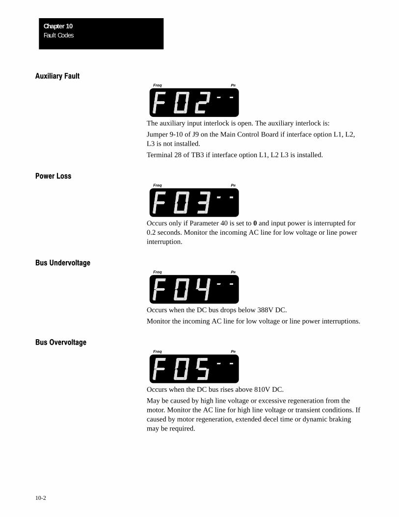
Fault CodesChapter 10
10-2
Auxiliary FaultFreq PR
The auxiliary input interlock is open. The auxiliary interlock is:
Jumper 9-10 of J9 on the Main Control Board if interface option L1, L2,L3 is not installed.
Terminal 28 of TB3 if interface option L1, L2 L3 is installed.
Power LossFreq PR
Occurs only if Parameter 40 is set to 0 and input power is interrupted for0.2 seconds. Monitor the incoming AC line for low voltage or line powerinterruption.
Bus UndervoltageFreq PR
Occurs when the DC bus drops below 388V DC.
Monitor the incoming AC line for low voltage or line power interruptions.
Bus OvervoltageFreq PR
Occurs when the DC bus rises above 810V DC.
May be caused by high line voltage or excessive regeneration from themotor. Monitor the AC line for high line voltage or transient conditions. Ifcaused by motor regeneration, extended decel time or dynamic brakingmay be required.
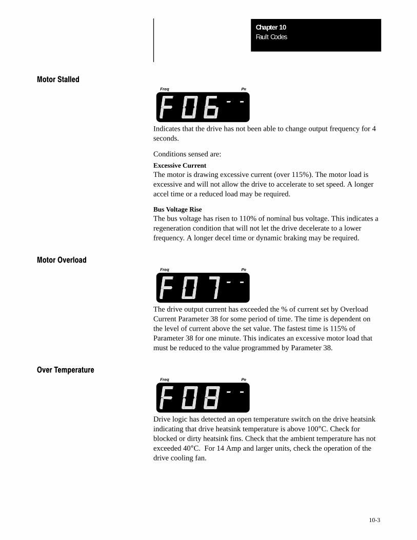
Fault CodesChapter 10
10-3
Motor StalledFreq PR
Indicates that the drive has not been able to change output frequency for 4seconds.
Conditions sensed are:
Excessive Curr entThe motor is drawing excessive current (over 115%). The motor load isexcessive and will not allow the drive to accelerate to set speed. A longeraccel time or a reduced load may be required.
Bus Voltage RiseThe bus voltage has risen to 110% of nominal bus voltage. This indicates aregeneration condition that will not let the drive decelerate to a lowerfrequency. A longer decel time or dynamic braking may be required.
Motor OverloadFreq PR
The drive output current has exceeded the % of current set by OverloadCurrent Parameter 38 for some period of time. The time is dependent onthe level of current above the set value. The fastest time is 115% ofParameter 38 for one minute. This indicates an excessive motor load thatmust be reduced to the value programmed by Parameter 38.
Over TemperatureFreq PR
Drive logic has detected an open temperature switch on the drive heatsinkindicating that drive heatsink temperature is above 100°C. Check forblocked or dirty heatsink fins. Check that the ambient temperature has notexceeded 40°C. For 14 Amp and larger units, check the operation of thedrive cooling fan.
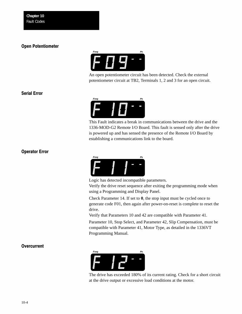
Fault CodesChapter 10
10-4
Open PotentiometerFreq PR
An open potentiometer circuit has been detected. Check the externalpotentiometer circuit at TB2, Terminals 1, 2 and 3 for an open circuit.
Serial ErrorFreq PR
This Fault indicates a break in communications between the drive and the1336-MOD-G2 Remote I/O Board. This fault is sensed only after the driveis powered up and has sensed the presence of the Remote I/O Board byestablishing a communications link to the board.
Operator ErrorFreq PR
Logic has detected incompatible parameters.Verify the drive reset sequence after exiting the programming mode whenusing a Programming and Display Panel.
Check Parameter 14. If set to 0, the stop input must be cycled once togenerate code F01, then again after power-on-reset is complete to reset thedrive.Verify that Parameters 10 and 42 are compatible with Parameter 41.
Parameter 10, Stop Select, and Parameter 42, Slip Compensation, must becompatible with Parameter 41, Motor Type, as detailed in the 1336VTProgramming Manual.
OvercurrentFreq PR
The drive has exceeded 180% of its current rating. Check for a short circuitat the drive output or excessive load conditions at the motor.
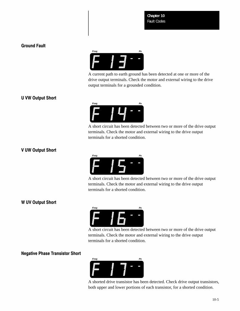
Fault CodesChapter 10
10-5
Ground FaultFreq PR
A current path to earth ground has been detected at one or more of thedrive output terminals. Check the motor and external wiring to the driveoutput terminals for a grounded condition.
U VW Output ShortFreq PR
A short circuit has been detected between two or more of the drive outputterminals. Check the motor and external wiring to the drive outputterminals for a shorted condition.
V UW Output ShortFreq PR
A short circuit has been detected between two or more of the drive outputterminals. Check the motor and external wiring to the drive outputterminals for a shorted condition.
W UV Output ShortFreq PR
A short circuit has been detected between two or more of the drive outputterminals. Check the motor and external wiring to the drive outputterminals for a shorted condition.
Negative Phase Transistor ShortFreq PR
A shorted drive transistor has been detected. Check drive output transistors,both upper and lower portions of each transistor, for a shorted condition.
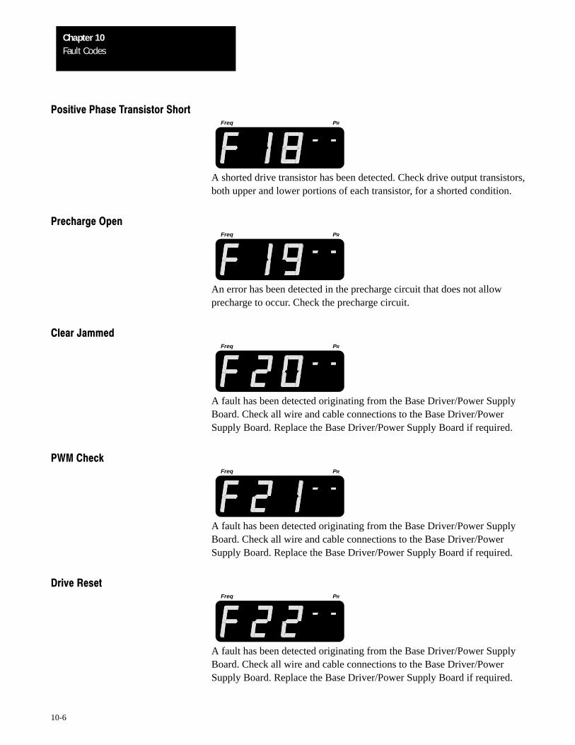
Fault CodesChapter 10
10-6
Positive Phase Transistor ShortFreq PR
A shorted drive transistor has been detected. Check drive output transistors,both upper and lower portions of each transistor, for a shorted condition.
Precharge OpenFreq PR
An error has been detected in the precharge circuit that does not allowprecharge to occur. Check the precharge circuit.
Clear JammedFreq PR
A fault has been detected originating from the Base Driver/Power SupplyBoard. Check all wire and cable connections to the Base Driver/PowerSupply Board. Replace the Base Driver/Power Supply Board if required.
PWM CheckFreq PR
A fault has been detected originating from the Base Driver/Power SupplyBoard. Check all wire and cable connections to the Base Driver/PowerSupply Board. Replace the Base Driver/Power Supply Board if required.
Drive ResetFreq PR
A fault has been detected originating from the Base Driver/Power SupplyBoard. Check all wire and cable connections to the Base Driver/PowerSupply Board. Replace the Base Driver/Power Supply Board if required.

Fault CodesChapter 10
10-7
Loop OverrunFreq PR
A fault has been detected originating from the Base Driver/Power SupplyBoard. Check all wire and cable connections to the Base Driver/PowerSupply Board. Replace the Base Driver/Power Supply Board if required.
Motor ModeFreq PR
A fault has been detected originating from the Base Driver/Power SupplyBoard. Check all wire and cable connections to the Base Driver/PowerSupply Board. Replace the Base Driver/Power Supply Board if required.
OverspeedFreq PR
A fault has been detected originating from the Base Driver/Power SupplyBoard. Check all wire and cable connections to the Base Driver/PowerSupply Board. Replace the Base Driver/Power Supply Board if required.
Power ModeFreq PR
A fault has been detected originating from the Base Driver/Power SupplyBoard. Check all wire and cable connections to the Base Driver/PowerSupply Board. Replace the Base Driver/Power Supply Board if required.
PWM LossFreq PR
A fault has been detected originating from the Base Driver/Power SupplyBoard. Check all wire and cable connections to the Base Driver/PowerSupply Board. Replace the Base Driver/Power Supply Board if required.
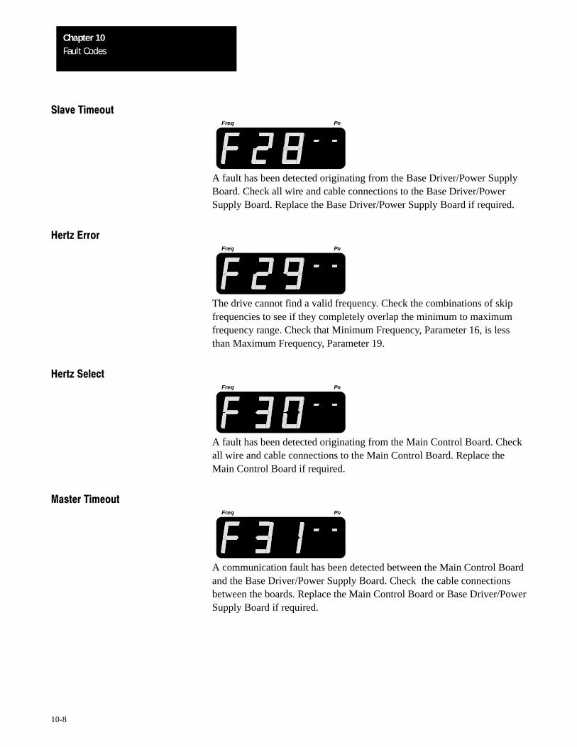
Fault CodesChapter 10
10-8
Slave TimeoutFreq PR
A fault has been detected originating from the Base Driver/Power SupplyBoard. Check all wire and cable connections to the Base Driver/PowerSupply Board. Replace the Base Driver/Power Supply Board if required.
Hertz ErrorFreq PR
The drive cannot find a valid frequency. Check the combinations of skipfrequencies to see if they completely overlap the minimum to maximumfrequency range. Check that Minimum Frequency, Parameter 16, is lessthan Maximum Frequency, Parameter 19.
Hertz SelectFreq PR
A fault has been detected originating from the Main Control Board. Checkall wire and cable connections to the Main Control Board. Replace theMain Control Board if required.
Master TimeoutFreq PR
A communication fault has been detected between the Main Control Boardand the Base Driver/Power Supply Board. Check the cable connectionsbetween the boards. Replace the Main Control Board or Base Driver/PowerSupply Board if required.
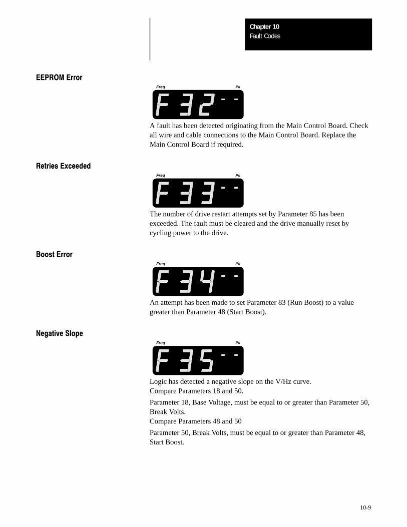
Fault CodesChapter 10
10-9
EEPROM ErrorFreq PR
A fault has been detected originating from the Main Control Board. Checkall wire and cable connections to the Main Control Board. Replace theMain Control Board if required.
Retries ExceededFreq PR
The number of drive restart attempts set by Parameter 85 has beenexceeded. The fault must be cleared and the drive manually reset bycycling power to the drive.
Boost ErrorFreq PR
An attempt has been made to set Parameter 83 (Run Boost) to a valuegreater than Parameter 48 (Start Boost).
Negative SlopeFreq PR
Logic has detected a negative slope on the V/Hz curve.Compare Parameters 18 and 50.
Parameter 18, Base Voltage, must be equal to or greater than Parameter 50,Break Volts.Compare Parameters 48 and 50
Parameter 50, Break Volts, must be equal to or greater than Parameter 48,Start Boost.
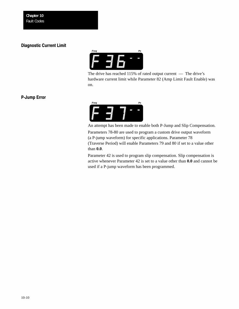
Fault CodesChapter 10
10-10
Diagnostic Current LimitFreq PR
The drive has reached 115% of rated output current –– The drive’shardware current limit while Parameter 82 (Amp Limit Fault Enable) wason.
PJump ErrorFreq PR
An attempt has been made to enable both P-Jump and Slip Compensation.
Parameters 78-80 are used to program a custom drive output waveform(a P-jump waveform) for specific applications. Parameter 78 (Traverse Period) will enable Parameters 79 and 80 if set to a value otherthan 0.0.
Parameter 42 is used to program slip compensation. Slip compensation isactive whenever Parameter 42 is set to a value other than 0.0 and cannot beused if a P-jump waveform has been programmed.
AAppendix
A-1
Logic Interface Options
1336MODL1 The Contact Closure Interface Board provides a means of interfacing+5V DC TTL Logic Contact various signals and commands to the 1336VT drive by using contactClosure Interface Board closures. The board is self-powered and does not require a separate user
power source. Plug in connectors on the Interface Board allow it to beplugged directly into connectors on the Main Control Board. Twomounting thumb screws secure the board in place.
!ATTENTION: If the Contact Closure Interface Board is toreplace either the 1336-MOD-L2 or 1336-MOD-L3, externalcircuits must be reconfigured to operate at the +5V DC logicpotentials supplied by the board. The application of either +24VDC or 115V AC to the Contact Closure Interface Board willdamage both the Interface Board and the Main Control Board.
Operation
Each of the twelve terminals on the board are defined as being either a usercommand input signal or interface common.
When an open circuit is present between a terminal and interface common,a +5V DC potential will exist. This represents the not selected state or high= False.
When a closed circuit is present between a terminal and interface common,the input will go low to approximately zero volts or true. When the inputsignal is pulled low to interface common, a sinking current of 15-20mAwill flow.
Requirements
Circuits used with the Contact Closure Interface Board must meet thefollowing criteria:
• Circuits must be capable of operating with low = True logic.
• In the low state, external circuits must be capable of a sinking current ofapproximately 20mA to pull the terminal voltage to 0.4V DC or less.
• In the high state, external circuits must allow the terminal voltage to riseto a voltage of 2.5-5V DC.
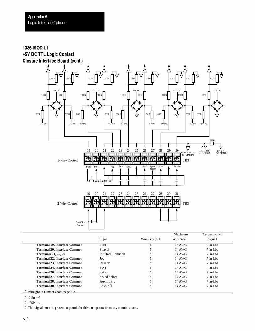
Logic Interface OptionsAppendix A
A-2
+5V DC+5V DC
100Ω
+5V DC
+5V DC
390Ω
4.7kΩ
390Ω
+5V DC
+5V DC
100Ω
4.7kΩ4.7kΩ
390Ω
100Ω
+5V DC
390Ω
+5V DC
+5V DC
100Ω
4.7kΩ4.7kΩ
390Ω
100Ω
+5V DC
390Ω
+5V DC
100Ω
4.7kΩ4.7kΩ
390Ω
100Ω
+5V DC
390Ω
+5V DC
100Ω
4.7kΩ4.7kΩ
390Ω
100Ω
EARTH19 20 21 22 23 24 25 26 27 28 29 30
Aux EnableRev SW2 SpeedSelect
I
GND
1336MODL1
+5V DC TTL Logic Contact
Closure Interface Board (cont.)
3-Wire Control TB3
19 20 21 22 23 24 25 26 27 28 29 30
2-Wire Control TB3
Start/StopContact
Start Stop Jog
+5V DC
SW1
GROUNDINTERFACECOMMON
CHASSISGROUND
Maximum RecommendedSignal Wire Group ❶ Wire Size ❷ Torque ❸
Terminal 19, Interface Common Start 5 14 AWG 7 In-LbsTerminal 20, Interface Common Stop ❹ 5 14 AWG 7 In-LbsTerminals 21, 25, 29 Interface Common 5 14 AWG 7 In-LbsTerminal 22, Interface Common Jog 5 14 AWG 7 In-LbsTerminal 23, Interface Common Reverse 5 14 AWG 7 In-LbsTerminal 24, Interface Common SW1 5 14 AWG 7 In-LbsTerminal 26, Interface Common SW2 5 14 AWG 7 In-LbsTerminal 27, Interface Common Speed Select 5 14 AWG 7 In-LbsTerminal 28, Interface Common Auxiliary ❹ 5 14 AWG 7 In-LbsTerminal 30, Interface Common Enable ❹ 5 14 AWG 7 In-Lbs
❶ Wire group number chart, page 6-3.
❷ 2.5mm2.
❸ .79N-m.
❹ This signal must be present to permit the drive to operate from any control source.
Logic Interface OptionsAppendix A
A-3
1336MODL1 Important: Control functions affected by drive parameter programming+5V DC TTL Logic Contact and selection are indicated on the following pages. Refer to the 1336VTClosure Interface Board (cont.) Programming Manual to verify that the drive is programmed to meet your
requirements.
If two-wire control is installed, option L1, L2 or L3 must also be installed.The 2-wire scheme allows a fault to be cleared by cycling the start/stopcontact if the following is true:
• Parameter 14 = 1
• Parameter 39 = 1
If Parameter 14 is not set to “1”, the drive can remain in an “F11” loop.Power must then be cycled in order to clear the fault.
!ATTENTION: Unexpected machine motion can cause injury ordeath. Do not use a Local or Remote Control Panel with option L1,L2, or L3 in any 2-wire start/stop control application.
A maintained start command or 2-wire control between terminals19 and 20 of TB3 on option L1, L2 or L3 will affect Control Panelstop pushbutton operation. The drive will automatically restart afterthe Control Panel stop pushbutton is depressed and released.
Logic Interface OptionsAppendix A
A-4
1336MODL1 Terminal 19 and Interface Common
+5V DC TTL Logic Contact
Closure Interface Board (cont.) Start
Momentary True = StartFalse = Continue Last State
This input will command the drive to start if all hardwired interlocks areclosed. The drive will continue to run until a stop command is received, aninterlock is opened, or a fault is detected. A maintained True state is notrequired to keep the drive running but is permitted. A False state isrequired to allow the drive to respond to a momentary stop input.
Terminal 20 and Interface Common
(This signal must be maintained as True to permit the drive
to operate from any control source.)
Stop
Maintained True = Not stop
Momentary False = Stop
Stop must be a maintained True input to permit the drive to start and run. Amomentary False input of 20mS or more or any other drive stop commandwill initiate a drive stop sequence as programmed by Parameter 10, StopSelect.
Terminals 21, 25, 29
Interface Common
Terminals 21, 25 and 29 are specifically used to terminate both minus orinterface common signals to TB3. For the 1336-MOD-L1 Interface Board,Terminals 21, 25 and 29 are also internally connected to drive signalcommon, chassis ground, and earth ground.
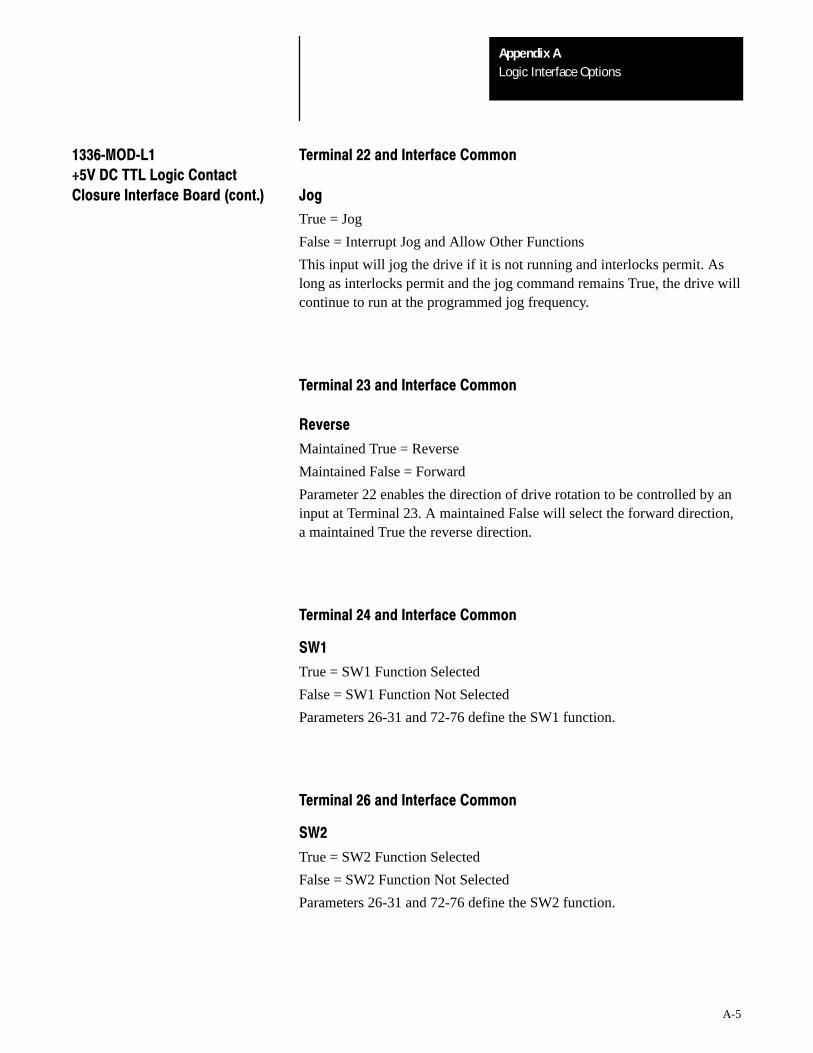
Logic Interface OptionsAppendix A
A-5
1336MODL1 Terminal 22 and Interface Common
+5V DC TTL Logic Contact
Closure Interface Board (cont.) Jog
True = Jog
False = Interrupt Jog and Allow Other Functions
This input will jog the drive if it is not running and interlocks permit. Aslong as interlocks permit and the jog command remains True, the drive willcontinue to run at the programmed jog frequency.
Terminal 23 and Interface Common
Reverse
Maintained True = Reverse
Maintained False = Forward
Parameter 22 enables the direction of drive rotation to be controlled by aninput at Terminal 23. A maintained False will select the forward direction,a maintained True the reverse direction.
Terminal 24 and Interface Common
SW1
True = SW1 Function Selected
False = SW1 Function Not Selected
Parameters 26-31 and 72-76 define the SW1 function.
Terminal 26 and Interface Common
SW2
True = SW2 Function Selected
False = SW2 Function Not Selected
Parameters 26-31 and 72-76 define the SW2 function.
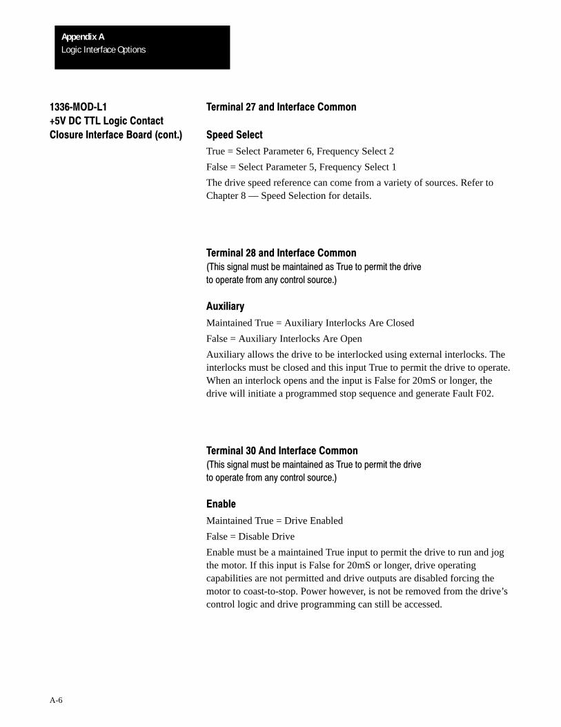
Logic Interface OptionsAppendix A
A-6
1336MODL1 Terminal 27 and Interface Common
+5V DC TTL Logic Contact
Closure Interface Board (cont.) Speed Select
True = Select Parameter 6, Frequency Select 2
False = Select Parameter 5, Frequency Select 1
The drive speed reference can come from a variety of sources. Refer toChapter 8 — Speed Selection for details.
Terminal 28 and Interface Common
(This signal must be maintained as True to permit the drive
to operate from any control source.)
Auxiliary
Maintained True = Auxiliary Interlocks Are Closed
False = Auxiliary Interlocks Are Open
Auxiliary allows the drive to be interlocked using external interlocks. Theinterlocks must be closed and this input True to permit the drive to operate.When an interlock opens and the input is False for 20mS or longer, thedrive will initiate a programmed stop sequence and generate Fault F02.
Terminal 30 And Interface Common
(This signal must be maintained as True to permit the drive
to operate from any control source.)
Enable
Maintained True = Drive Enabled
False = Disable Drive
Enable must be a maintained True input to permit the drive to run and jogthe motor. If this input is False for 20mS or longer, drive operatingcapabilities are not permitted and drive outputs are disabled forcing themotor to coast-to-stop. Power however, is not be removed from the drive’scontrol logic and drive programming can still be accessed.

Logic Interface OptionsAppendix A
A-7
1336MODL2 +24V DC The +24V DC Logic Interface Board provides a means of interfacingLogic Interface Board various signals and commands to the 1336VT drive using +24V DC
signals. A +24V DC power source must be supplied by the user for theboard to operate. Plug in connectors on the +24V DC Interface Boardallow it to be plugged directly into connectors on the Main Control Board.Two mounting thumb screws secure the board in place.
!ATTENTION: If the +24V DC Interface Board is to replaceeither the 1336-MOD-L1 or 1336-MOD-L3, external circuits mustbe reconfigured to operate at the +24V DC logic potentials requiredby the board. The application of either +5V DC or 115V AC to the+24V DC Interface Board will damage both the +24V DC InterfaceBoard and the Main Control Board.
Operation
Each of the twelve terminals on the board are defined as being either a usercommand input signal or interface common.
When a closed circuit is present between a terminal and interface common,a +20 to +26V DC potential will exist. This represents the selected state orhigh = True.
When an open circuit is present between a terminal and interface common,the input will go lower to a False state.
Requirements
Circuits used with the +24V DC Logic Interface Board must meet thefollowing criteria:
• Circuits must be capable of operating with high = True logic.
• In the low state, circuits must generate a voltage of no more than 3.0VDC. The leakage current must be less than 1mA into a 2.8kΩ load.
• In the high state, circuits must generate a voltage of +20 to +26V DCand source a current of approximately 8.5mA for each input.
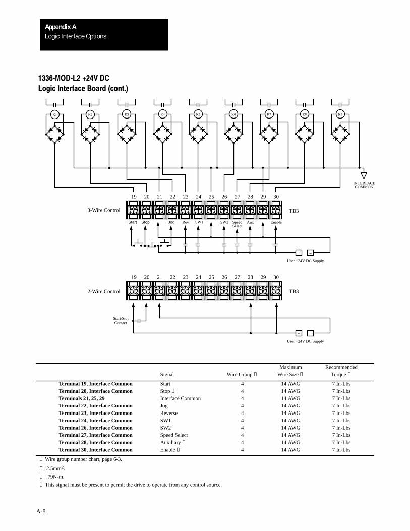
Logic Interface OptionsAppendix A
A-8
I
K9K8K7K6K5K4K3K2K1
3-Wire Control
2-Wire Control TB3
19 20 21 22 23 24 25 26 27 28 29 30
+ –
User +24V DC Supply
TB3
19 20 21 22 23 24 25 26 27 28 29 30
+ –
User +24V DC Supply
Aux EnableRev SW2 SpeedSelect
Start/StopContact
Start Stop Jog
INTERFACECOMMON
SW1
1336MODL2 +24V DC
Logic Interface Board (cont.)
Maximum RecommendedSignal Wire Group ❶ Wire Size ❷ Torque ❸
Terminal 19, Interface Common Start 4 14 AWG 7 In-LbsTerminal 20, Interface Common Stop ❹ 4 14 AWG 7 In-LbsTerminals 21, 25, 29 Interface Common 4 14 AWG 7 In-LbsTerminal 22, Interface Common Jog 4 14 AWG 7 In-LbsTerminal 23, Interface Common Reverse 4 14 AWG 7 In-LbsTerminal 24, Interface Common SW1 4 14 AWG 7 In-LbsTerminal 26, Interface Common SW2 4 14 AWG 7 In-LbsTerminal 27, Interface Common Speed Select 4 14 AWG 7 In-LbsTerminal 28, Interface Common Auxiliary ❹ 4 14 AWG 7 In-LbsTerminal 30, Interface Common Enable ❹ 4 14 AWG 7 In-Lbs
❶ Wire group number chart, page 6-3.
❷ 2.5mm2.
❸ .79N-m.
❹ This signal must be present to permit the drive to operate from any control source.
Logic Interface OptionsAppendix A
A-9
1336MODL2 +24V DC Important: Control functions affected by drive Parameter programmingLogic Interface Board (cont.) and selection are indicated on the following pages. Refer to the 1336VT
Programming Manual to verify that the drive is programmed to meet yourrequirements.
If two-wire control is installed, option L1, L2 or L3 must also be installed.The 2-wire scheme allows a fault to be cleared by cycling the start/stopcontact if the following is true:
• Parameter 14 = 1
• Parameter 39 = 1
If Parameter 14 is not set to “1”, the drive can remain in an “F11” loop.Power must then be cycled in order to clear the fault.
!ATTENTION: Unexpected machine motion can cause injury ordeath. Do not use a Local or Remote Control Panel with option L1,L2, or L3 in any 2-wire start/stop control application.
A maintained start command or 2-wire control between terminals19 and 20 of TB3 on option L1, L2 or L3 will affect Control Panelstop pushbutton operation. The drive will automatically restart afterthe Control Panel stop pushbutton is depressed and released.
Terminal 19 and Interface Common
Start
Momentary True = Start
False = Continue Last State
This input will command the drive to start if all hardwired interlocks areclosed. The drive will continue to run until a stop command is received, aninterlock is opened, or a fault is detected. A maintained True state is notrequired to keep the drive running but is permitted. A False state isrequired to allow the drive to respond to a momentary stop input.
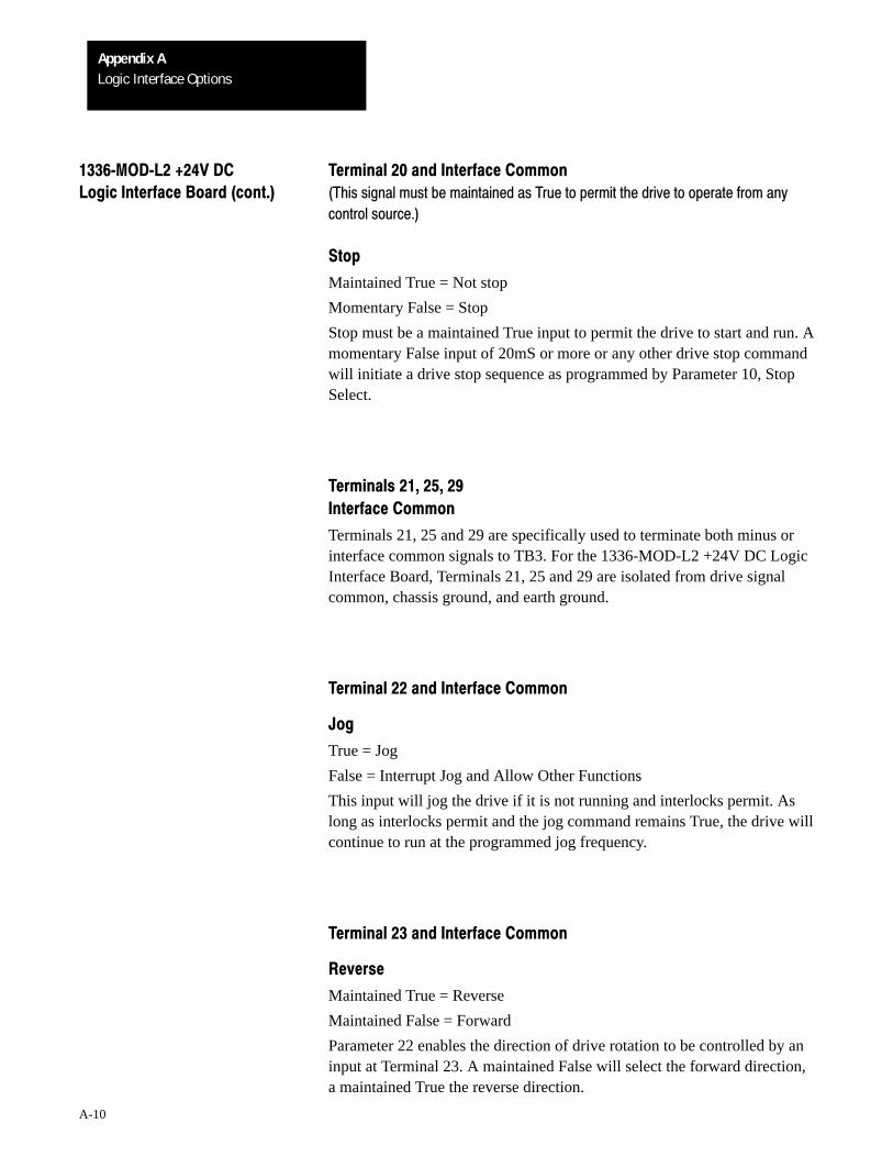
Logic Interface OptionsAppendix A
A-10
1336MODL2 +24V DC Terminal 20 and Interface Common
Logic Interface Board (cont.) (This signal must be maintained as True to permit the drive to operate from any
control source.)
Stop
Maintained True = Not stop
Momentary False = Stop
Stop must be a maintained True input to permit the drive to start and run. Amomentary False input of 20mS or more or any other drive stop commandwill initiate a drive stop sequence as programmed by Parameter 10, StopSelect.
Terminals 21, 25, 29
Interface Common
Terminals 21, 25 and 29 are specifically used to terminate both minus orinterface common signals to TB3. For the 1336-MOD-L2 +24V DC LogicInterface Board, Terminals 21, 25 and 29 are isolated from drive signalcommon, chassis ground, and earth ground.
Terminal 22 and Interface Common
Jog
True = Jog
False = Interrupt Jog and Allow Other Functions
This input will jog the drive if it is not running and interlocks permit. Aslong as interlocks permit and the jog command remains True, the drive willcontinue to run at the programmed jog frequency.
Terminal 23 and Interface Common
Reverse
Maintained True = Reverse
Maintained False = Forward
Parameter 22 enables the direction of drive rotation to be controlled by aninput at Terminal 23. A maintained False will select the forward direction,a maintained True the reverse direction.
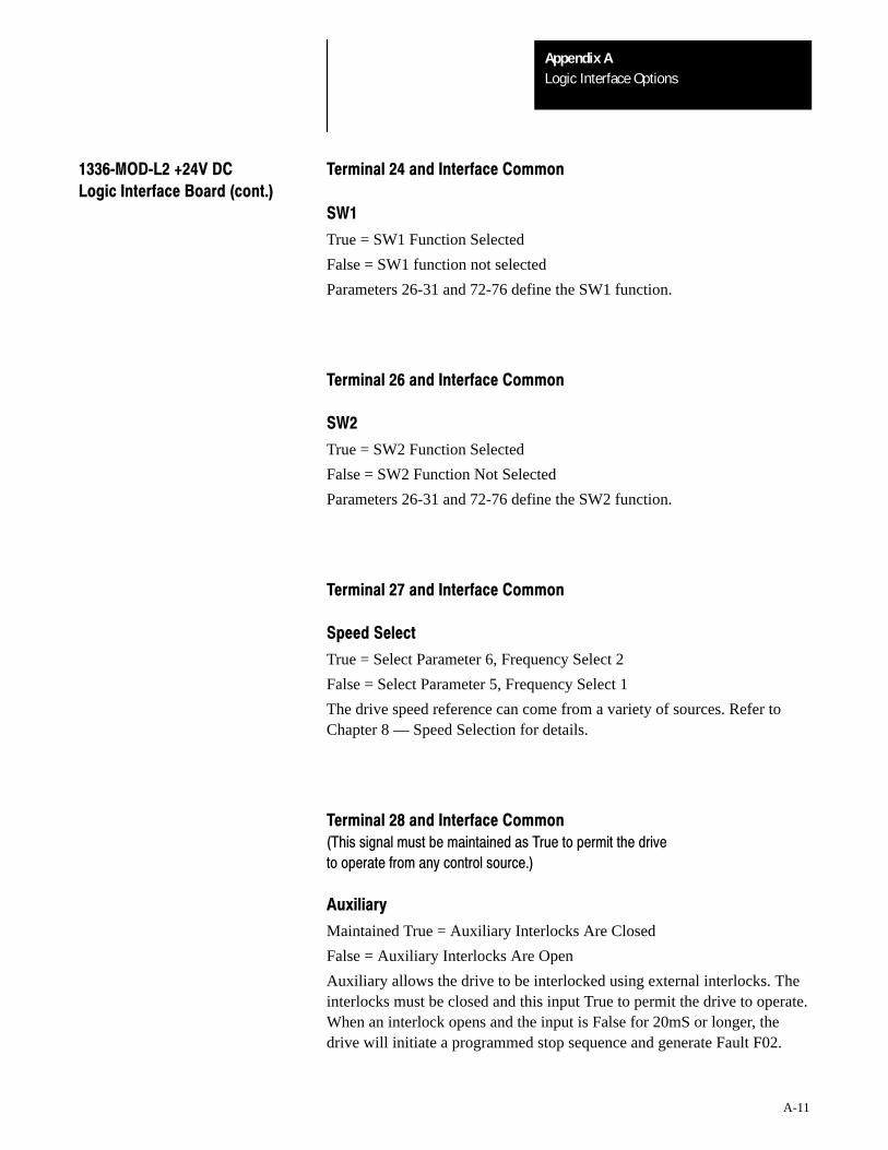
Logic Interface OptionsAppendix A
A-11
1336MODL2 +24V DC Terminal 24 and Interface Common
Logic Interface Board (cont.)
SW1
True = SW1 Function Selected
False = SW1 function not selected
Parameters 26-31 and 72-76 define the SW1 function.
Terminal 26 and Interface Common
SW2
True = SW2 Function Selected
False = SW2 Function Not Selected
Parameters 26-31 and 72-76 define the SW2 function.
Terminal 27 and Interface Common
Speed Select
True = Select Parameter 6, Frequency Select 2
False = Select Parameter 5, Frequency Select 1
The drive speed reference can come from a variety of sources. Refer toChapter 8 — Speed Selection for details.
Terminal 28 and Interface Common
(This signal must be maintained as True to permit the drive
to operate from any control source.)
Auxiliary
Maintained True = Auxiliary Interlocks Are Closed
False = Auxiliary Interlocks Are Open
Auxiliary allows the drive to be interlocked using external interlocks. Theinterlocks must be closed and this input True to permit the drive to operate.When an interlock opens and the input is False for 20mS or longer, thedrive will initiate a programmed stop sequence and generate Fault F02.
Logic Interface OptionsAppendix A
A-12
1336MODL2 +24V DC Terminal 30 and Interface Common
Logic Interface Board (cont.) (This signal must be maintained as True to permit the drive to operate from any
control source.)
Enable
Maintained True = Drive Enabled
False = Disable Drive
Enable must be a maintained True input to permit the drive to run and jogthe motor. If this input is False for 20mS or longer, drive operatingcapabilities are not permitted and drive outputs are disabled forcing themotor to coast-to-stop. Power however, is not be removed from the drive’scontrol logic and drive programming can still be accessed.
Logic Interface OptionsAppendix A
A-13
1336MODL3 115V AC The 115V AC Logic Interface Board provides a means of interfacingLogic Interface Board various signals and commands to the 1336VT drive using 115V AC
signals. A 115V AC power source must be supplied by the user for theboard to operate. Plug in connectors on the 115V AC Interface Board allowit to be plugged directly into connectors on the Main Control Board. Twomounting thumb screws secure the board in place.
!ATTENTION: If the 115V AC Interface Board is to replace eitherthe 1336-MOD-L1 or 1336-MOD-L2, external circuits must bereconfigured to operate at the 115V AC logic potentials required bythe board. The application of either +5V DC or +24V AC to the115V AC Interface Board will damage both the 115V AC InterfaceBoard and the Main Control Board
Operation
Each of the twelve terminals on the board are defined as being either a usercommand input signal or interface common.
When a closed circuit is present between a terminal and interface common,a 115V AC potential will exist. This represents the selected state or high =True.
When an open circuit is present between a terminal and interface common,the input will go lower to a False state.
Requirements
Circuits used with the 115V AC Logic Interface Board must meet thefollowing criteria:
• Circuits must be capable of operating with high = True logic.
• In the low state, circuits must generate a voltage of no more than 10.0VAC. The leakage current must be less than 1mA into a 13kΩ load.
• In the high state, circuits must generate a voltage of 115V AC ±10% andsource a current of approximately 8.5mA for each input.
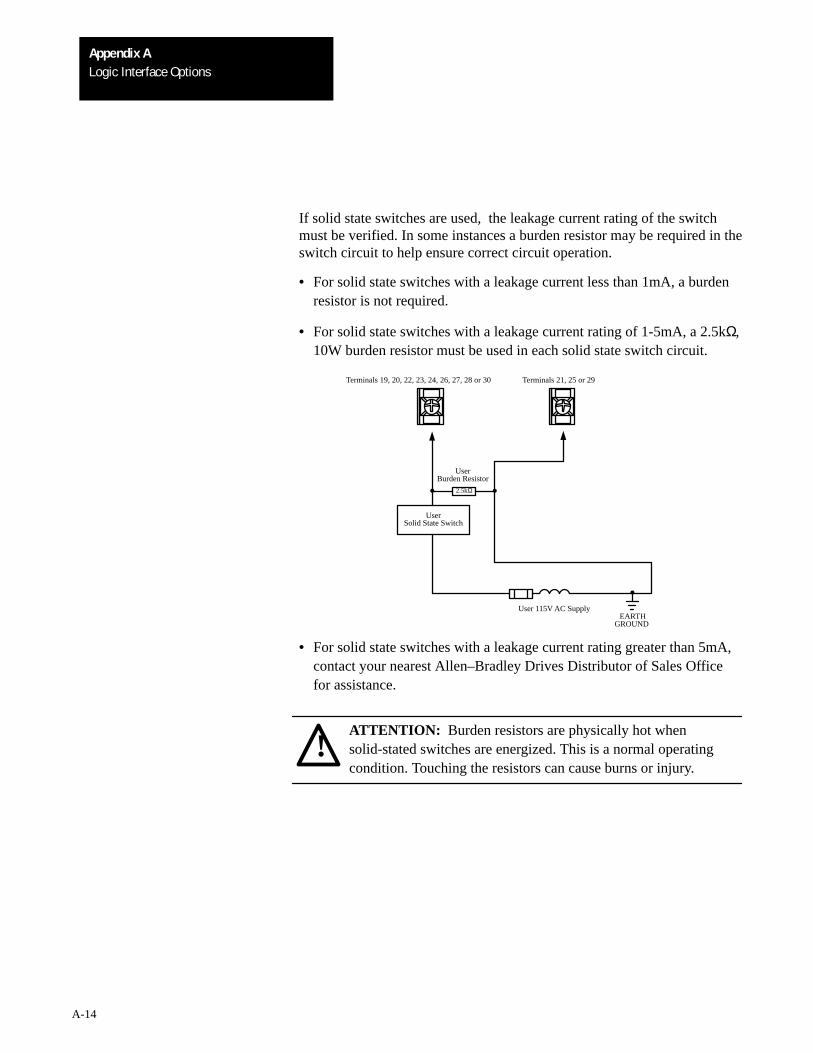
Logic Interface OptionsAppendix A
A-14
If solid state switches are used, the leakage current rating of the switchmust be verified. In some instances a burden resistor may be required in theswitch circuit to help ensure correct circuit operation.
• For solid state switches with a leakage current less than 1mA, a burdenresistor is not required.
• For solid state switches with a leakage current rating of 1-5mA, a 2.5kΩ,10W burden resistor must be used in each solid state switch circuit.
2.5kΩ
User 115V AC SupplyEARTH
GROUND
UserSolid State Switch
UserBurden Resistor
Terminals 21, 25 or 29Terminals 19, 20, 22, 23, 24, 26, 27, 28 or 30
• For solid state switches with a leakage current rating greater than 5mA,contact your nearest Allen–Bradley Drives Distributor of Sales Officefor assistance.
!ATTENTION: Burden resistors are physically hot whensolid-stated switches are energized. This is a normal operatingcondition. Touching the resistors can cause burns or injury.
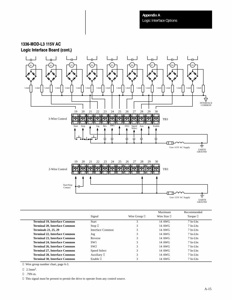
Logic Interface OptionsAppendix A
A-15
5.6kΩ 5.6kΩ 5.6kΩ 5.6kΩ 5.6kΩ 5.6kΩ 5.6kΩ 5.6kΩ 5.6kΩ 5.6kΩ 5.6kΩ 5.6kΩ 5.6kΩ 5.6kΩ 5.6kΩ5.6kΩ5.6kΩ 5.6kΩ
19 20 21 22 23 24 25 26 27 28 29 30
I
K9K8K7K6K5K4K3K2K1
Aux EnableStart Stop Jog Rev SW2 SpeedSelect
User 115V AC SupplyEARTH
GROUND
3-Wire Control
2-Wire Control TB3
TB3
19 20 21 22 23 24 25 26 27 28 29 30
User 115V AC Supply
Start/StopContact
INTERFACECOMMON
SW1
EARTHGROUND
1336MODL3 115V AC
Logic Interface Board (cont.)
Maximum RecommendedSignal Wire Group ❶ Wire Size ❷ Torque ❸
Terminal 19, Interface Common Start 3 14 AWG 7 In-LbsTerminal 20, Interface Common Stop ❹ 3 14 AWG 7 In-LbsTerminals 21, 25, 29 Interface Common 3 14 AWG 7 In-LbsTerminal 22, Interface Common Jog 3 14 AWG 7 In-LbsTerminal 23, Interface Common Reverse 3 14 AWG 7 In-LbsTerminal 24, Interface Common SW1 3 14 AWG 7 In-LbsTerminal 26, Interface Common SW2 3 14 AWG 7 In-LbsTerminal 27, Interface Common Speed Select 3 14 AWG 7 In-LbsTerminal 28, Interface Common Auxiliary ❹ 3 14 AWG 7 In-LbsTerminal 30, Interface Common Enable ❹ 3 14 AWG 7 In-Lbs
❶ Wire group number chart, page 6-3.
❷ 2.5mm2.
❸ .79N-m.
❹ This signal must be present to permit the drive to operate from any control source.

Logic Interface OptionsAppendix A
A-16
1336MODL3 115V AC Important: Control functions affected by drive Parameter programmingLogic Interface Board and selection are indicated on the following pages. Refer to the 1336VT
Programming Manual to verify that the drive is programmed to meet yourrequirements.
If two-wire control is installed, option L1, L2 or L3 must also be installed.The 2-wire scheme allows a fault to be cleared by cycling the start/stopcontact if the following is true:
• Parameter 14 = 1
• Parameter 39 = 1
If Parameter 14 is not set to “1”, the drive can remain in an “F11” loop.Power must then be cycled in order to clear the fault.
!ATTENTION: Unexpected machine motion can cause injury ordeath. Do not use a Local or Remote Control Panel with option L1,L2, or L3 in any 2-wire start/stop control application.
A maintained start command or 2-wire control between terminals19 and 20 of TB3 on option L1, L2 or L3 will affect Control Panelstop pushbutton operation. The drive will automatically restart afterthe Control Panel stop pushbutton is depressed and released.
Terminal 19 and Interface Common
Start
Momentary True = Start
False = Continue Last State
This input will command the drive to start if all hardwired interlocks areclosed. The drive will continue to run until a stop command is received, aninterlock is opened, or a fault is detected. A maintained True state is notrequired to keep the drive running but is permitted. A False state isrequired to allow the drive to respond to a momentary stop input.
Logic Interface OptionsAppendix A
A-17
1336MODL3 115V AC Terminal 20 and Interface Common
Logic Interface Board (This signal must be maintained as True to permit the drive to operate from any
control source.)
Stop
Maintained True = Not Stop
Momentary False = Stop
Stop must be a maintained True input to permit the drive to start and run. Amomentary False of 90mS or more or any other drive stop command willinitiate a drive stop sequence as programmed by Parameter 10, Stop Select.
Terminals 21, 25, 29
Interface Common
Terminals 21, 25 and 29 are used to terminate both minus or interfacecommon signals to TB3. Terminals 21, 25 and 29 are also used to terminateany shields for cables connected to TB3. For the 1336-MOD-L3 115V ACLogic Interface Board, Terminals 21, 25 and 29 are isolated from drivesignal common, chassis ground, and earth ground.
Terminal 22 and Interface Common
Jog
True = Jog
False = Interrupt Jog and Allow Other Functions
This input will jog the drive if it is not running and interlocks permit. Aslong as interlocks permit and the jog command remains True, the drive willcontinue to run at the programmed jog frequency.
Terminal 23 and Interface Common
Reverse
Maintained True = Reverse
Maintained False = Forward
Parameter 22 enables the direction of drive rotation to be controlled by aninput at Terminal 23. A maintained False will select the forward direction,a maintained true the reverse direction.
Logic Interface OptionsAppendix A
A-18
1336MODL3 115V AC Terminal 24 and Interface Common
Logic Interface Board SW1
True = SW1 Function Selected
False = SW1 Function Not Selected
Parameters 26-31 and 72-76 define the SW1 function.
Terminal 26 and Interface Common
SW2
True = SW2 Function Selected
False = SW2 Function Not Selected
Parameters 26-31 and 72-76 define the SW2 function.
Terminal 27 and Interface Common
Speed Select
True = Select Parameter 6, Frequency Select 2
False = Select Parameter 5, Frequency Select 1
The drive speed reference can come from a variety of sources. Refer toChapter 8 — Speed Selection for details.
Terminal 28 and Interface Common
(This signal must be maintained as True to permit the drive
to operate from any control source.)
Auxiliary
Maintained True = Auxiliary Interlocks Are Closed
False = Auxiliary Interlocks Are Open
Auxiliary allows the drive to be interlocked using external interlocks. Theinterlocks must be closed and this input True to permit the drive to operate.When an interlock opens and the input is False for 90mS or longer, thedrive will initiate a programmed stop sequence and generate Fault F02.
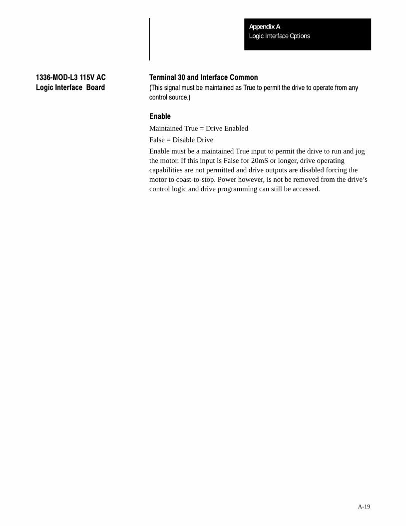
Logic Interface OptionsAppendix A
A-19
1336MODL3 115V AC Terminal 30 and Interface Common
Logic Interface Board (This signal must be maintained as True to permit the drive to operate from any
control source.)
Enable
Maintained True = Drive Enabled
False = Disable Drive
Enable must be a maintained True input to permit the drive to run and jogthe motor. If this input is False for 20mS or longer, drive operatingcapabilities are not permitted and drive outputs are disabled forcing themotor to coast-to-stop. Power however, is not be removed from the drive’scontrol logic and drive programming can still be accessed.
Publication 1336VT-5.0 March, 1994 P/N 163734Supersedes July, 1993 Copyright 1994, AllenBradley Company, Inc. Printed in USA
Recommended