Upendra N Singh1, Jirong Yu1, Yingxin Bai2, Mulugeta Petros1 and Songsheng Chen1
1NASA Langley Research Center, Hampton, VA 2Science Systems and Applications, Inc, One Enterprise Parkway, Hampton, VA
SOLID-STATE, HIGH REPETITION RATE TM: FIBER PUMPED HO:YLF 2-ΜM COHERENT LASER TRANSMITTER FOR AIR AND SPACE-BASED
CO2 MEASUREMENTS
Acknowledgement: Research and development under NASA Laser Risk Reduction Program funded by NASA Earth Science Technology Office (ESTO)
(Program Director: George Komar)

Outline• Background• 2-micron Pulsed Lidar Approach for CO2
Measurement• 2-micron Pulsed Coherent Detection Lidar- for
Mobile Ground-based CO2 Profiling• 2-micron Pulsed Direct Detection IPDA Lidar for
CO2 Column Measurement from Airborne Platform• Summary

Pulsed Lidar Approach• The National Academies has identified CO2 measurement
from space as a critical mission for study of climate change and global warming
• NASA has planned Active Sensing Of CO2 Emissions Over Nights, Days, And Seasons (ASCENDS) mission for CO2
column measurements from space
• For column measurements, the pulsed lidar approach can eliminate contamination from aerosols and clouds to yield high accuracy measurements
• The pulse approach can determine CO2 concentrations as a function of distance with high spatial and temporal resolution, a valuable data product that is not currently available

CO2 Absorption Line at 2-micron
2.040 2.045 2.050 2.055 2.060 2.065 2.070 2.075 2.0800.00E+000
2.00E-022
4.00E-022
6.00E-022
8.00E-022
1.00E-021
1.20E-021
1.40E-021
CO
2 ab
sorp
tion
cro
ss s
ecti
on (
cm2 )
Wavelength (m)
% (P=1013.25mbar T=296K Volume Mixing Ratio=0.1)
2.0508 2.0509 2.0510 2.0511 2.0512 2.05130.00E+000
2.00E-022
4.00E-022
6.00E-022
8.00E-022
1.00E-021
1.20E-021
1.40E-021
CO
2 ab
sorp
tion
cro
ss s
ecti
on (c
m2 )
Wavelength (m)
% (P=1013.25mbar T=296K )Volume Mixing Ratio=0.1)
R30 lineLine Center
Off Line
On Line

Atmospheric Testing—2007 Results• DIAL at better than 0.7%
precision for column over ½ hour (9000 pulses).• Range-resolved at better than
2.4% on500-m bins and 6.7 minutes (2000 pulses)Improvements for 2010 Tests
• Higher pulse energy (90mJ to 250mJ) for higher SNR.
• Higher pulse repetition rate (5Hz to 10 Hz) for more pulse averaging.
• Double pulsing format for more pulse averaging and better atmospheric sampling.
• More favorable line (R30) for less water vapor bias.
380
390
400
410
420
430
380
390
400
410
420
430
in-situ sensor
DIAL 6.7 minute integration DIAL 30 minute rolling average
CO
2 con
cent
ratio
n (p
pm)
time (local)
6:00 7:00 8:00 9:00 10:00 11:00 12:00
sunrise
G.J. Koch et. al., Applied Optics 47, (7), 944-956 (Mar. 2008)
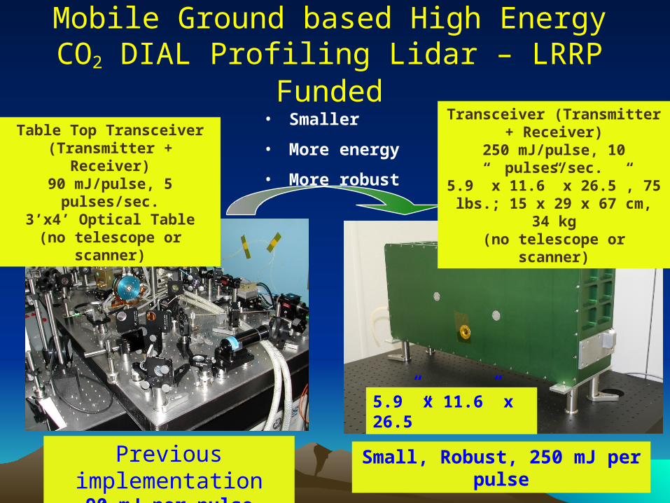
Previous implementation90 mJ per pulse
Small, Robust, 250 mJ per pulse
Transceiver (Transmitter + Receiver)
250 mJ/pulse, 10 pulses/sec.5.9” x 11.6” x 26.5”, 75 lbs.; 15 x
29 x 67 cm, 34 kg(no telescope or scanner)
5.9” x 11.6” x 26.5”
• Smaller
• More energy
• More robust
Table Top Transceiver (Transmitter + Receiver)90 mJ/pulse, 5 pulses/sec.
3’x4’ Optical Table(no telescope or scanner)
Mobile Ground based High Energy CO2 DIAL Profiling Lidar – LRRP Funded

Double Pulsed 2-µm Laser Operation
0.0000 0.0005 0.0010 0.00150.0
0.1
0.2
0.3
0.4
0.5
Re
lativ
e H
o p
op
ula
tion
in 5
I7
Time (s) 0 20 40 60 80 100 120 140 160 180
0.0
0.4
0.8
1.2
1.6
FWHM = 137ns
Double Pulses (Iosc.= 65A)
Time between two pulses = 150 s
Am
plit
ud
e (
arb
. Un
it)
Time (s)
-0.6 -0.3 0.0 0.3 0.60.0
0.5
1.0
Time (s)
-0.8 -0.4 0.0 0.4 0.8
0.0
0.5
1.0 FWHM
= 230ns
Time (s)

Pulsed Coherent CO2 DIAL
• Pulsed 2-micron laser transmitter• 250 mJ/10Hz
• Coherent DIAL• Provide CO2 profiling/column density
measurement
Transceiver
(2 micron Laser and
Receiver electronics)
6” Telescope & Steering Mirrors
Seeding & Wave-length Locking Control
19” Electronic Rack:
1. Laser Control Electronics 5U (8.75”)
2. DAS Analog Processing 3U (5.25”)
3. PXI Controller 3U (5.25”)
4. User Interface Computer 3U (5.25”)
Cooling System Transmit
Return
Signals & Feedback
Control

On-Off Return Signal
0 1000 2000 3000 4000 5000 6000 7000 8000 9000-38
-36
-34
-32
-30
-28
-26
-24
-22
-20
-18
-16
P
ow
er
Sp
ectr
um
De
nsity
Range (meter)
Off-line 2G 3G 4G

• Pulsed 2 mm lidar, with ranging capabilities, provides a direct measurement of the atmospheric CO2 path
• Provides high sensitivity in the boundary layer with no bias from aerosol layers and clouds on the measurement accuracy
• Higher per-pulse SNR (signal-to-noise ratio) obtainable with high energy 2 mm pulsed backscatter means less reliance on multi-pulse averaging, providing potential for higher along-track spatial resolution and better measurement capability in regions of partial cloud coverage, benefiting high precision measurements.
• Operating at 2 mm results in a weighting function that peaks near the surface
• Technical Challenges for IPDA Lidar Transmitter:• High efficiency• High average power• Good beam quality• Single frequency• Wavelength switching and controlling
Pulsed 2 mm Direct Detection IPDA Lidar System for CO2 Column Measurement

Advanced-Space Carbon and Climate Observation of Planet Earth Mission Studies
• A-SCOPE: Scientific objective: The observation of the spatial and temporal gradients of atmospheric XCO2 with a precision and accuracy sufficient to constrain CO2 fluxes within 0.02 Pg C yr-1 on a scale of 1000 x 1000 km2.
• A-SCOPE: IPDA: Instrument Parameters for two wavelengths (1.57 and 2.05 micron)
A
Transmitter WavelengthPulse EnergyPulse Repetition FrequencySpectral line width
ReceiverTelescope diameter
DetectorQuantum efficiencyNoise Equivalent Power
1.57 m 50 mJ50 Hz
50 MHz
1 m
0.7446 fW/Hz0.5
2.05 m 55 mJ50 Hz
50 MHz
1.2 m
0.75100 fW/Hz0.5
European Space Agency (ESA), “A-SCOPE – Advanced Space Carbon and Climate Observation of Planet Earth, Report For Assessment”, ESA-SP1313/1 (2008), available at http://esamultimedia.esa.int/docs/SP1313-1_ASCOPE.pdf.Ehret G., Kiemle C., Wirth M., Amediek A., Fix A., Houweling S., “Space-borne remote sensing of CO2, CH4, and N2O by integrated path differential absorption lidar: a sensitivity analysis”, Applied Physics B 90, 593-608 (2008), an comprehensive study funded by European Space Agency under contract No.10880/03/NL/FF

Ho Laser Energy Level Diagram
Tm:fiber Laser Pumping0.78/0.792mm Diode Pumping
low heat loading (5% pump power)less up-conversion
high efficiencyCW/high repetition operation
Ho3+
Laser pump
1.94mm
2.06mm
2.05mm 5I8
5I7
Tm3+ Ho3+
Light pump
Dipole-dipole
0.79
2mm
1.94mm
2.06mm
2.05mm
5I7
5I83H6
3H4
3F4
heat loading (23% pump power) up conversion
Low repetition rate

Schematics of Lidar Transmitter
Tm fiber laser HoAmplifier
WavelengthControl
HoOscillator
Commercially available
Technology demonstrated and bread boarded; compacting and packaging is planned
Technology need to be developed/improved/demonstrated; system engineering and packaging is planned

O.C.
Q.Switch.
Pm
Ho:YLF
HeNe
Tm:Fiber laser
M1
M2
M3
M4
M5M6M7
M8
PSeed Laser
Output
Faraday Isolatorsl/2
PZT
M9F
D1
The pump, oscillator, and seed beams are all mode-matched.
Master Slave Laser System

0 2 4 6 8 10 12 140
5
10
15
20
25
30
35100nS
Th
e o
utp
ut
pu
lse
ener
gy
(m
J)
Tm:fiber laser pump power (W)
Ho:YLF Oscillator Performance (100 Hz)

Oscillator Performance (High RR)
0 2 4 6 8 10 12 14 160
1
2
3
4
5
6
Th
e ou
tpu
t p
uls
e en
ergy (
mJ)
Tm:fiber laser pump power (W)
1 KHz
0 2 4 6 8 10 12 14 160.0
0.5
1.0
1.5
2.0
2.5
3.0
Th
e o
utp
ut
pu
lse e
nergy (
mJ)
Tm:fiber laser pump power (W)
2 KHz
0 2 4 6 8 10 12 14 160.0
0.2
0.4
0.6
0.8
1.0
Th
e o
utp
ut
pu
lse e
nergy (
mJ)
Tm:fiber laser pump power (W)
7.5 KHz
0 2 4 6 8 10 12 14 160.0
0.1
0.2
0.3
0.4
0.5
0.6
0.7
0.8
Th
e o
utp
ut
pu
lse e
nergy (
mJ)
Tm:fiber laser pump power (W)
10 KHz
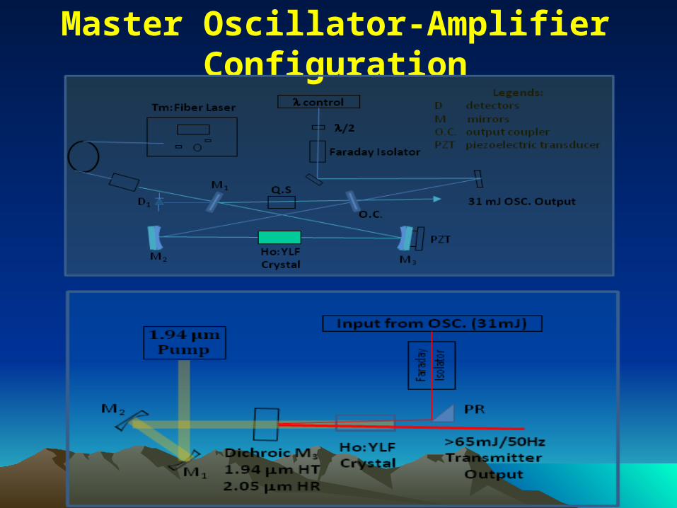
Master Oscillator-Amplifier Configuration

Breadboard Seed Lasers Schematic

Lidar Components
Thulium-Fiber Pump LaserRuggedly Packaged 80 W laser
CO2 DIAL/IPDA Wavelength ControlPrototype wavelength and control layout
CO2 DIAL/IPDA Telescope
CO2 DIAL/IPDA ElectronicsCO2 DIAL/IPDA Data Acquisition System

2-micron Laser Transmitter Specifications
Parameter Development Objectives for Current
System
Target Objectives for Space-based System
Wavelength (µm) 2.051 2.051
Energy(mJ)/ Rep. Rate (Hz)
>65mJ / 50Hz 65mJ / 50Hz
Pulse width (ns) <= 50ns <= 50nsTransverse Mode TEMoo TEMoo
Longitudinal mode Single frequency Single frequency
Frequency Control accuracy
<2MHz 2MHz

Summary• NASA Earth Science Technology Office (ESTO) funded 2-micron Doppler
lidar technology under LRRP was heavily leveraged in developing high energy, pulsed 2-micron coherent lidar system for ground-based CO2 profiling. The system was field tested in Wisconsin during 2007
• 2-micron team has successfully developed a double-pulsed, high energy coherent DIAL system and demonstrated ground based measurement
• Accurate laser wavelength control and switching has been demonstrated, which meets the frequency stability and accuracy requirement for the CO2 DIAL
• The NASA LaRC developed Ho pulse laser meets or exceeds the generally accepted requirements of a direct detection 2µm IPDA system, which can provide adequate CO2 column density measurements from space
• The pulsed lidar transmitter architecture, energy, repetition rate, line width, frequency control are all suitable for space application without major scale up requirements.
Recommended


![1 1 1 1 1 1 1 ¢ 1 1 1 - pdfs.semanticscholar.org€¦ · 1 1 1 [ v . ] v 1 1 ¢ 1 1 1 1 ý y þ ï 1 1 1 ð 1 1 1 1 1 x](https://img.pdfslide.us/doc/110x75/5f7bc722cb31ab243d422a20/1-1-1-1-1-1-1-1-1-1-pdfs-1-1-1-v-v-1-1-1-1-1-1-y-1-1-1-.jpg)


![1 1 1 1 1 1 1 ¢ 1 , ¢ 1 1 1 , 1 1 1 1 ¡ 1 1 1 1 · 1 1 1 1 1 ] ð 1 1 w ï 1 x v w ^ 1 1 x w [ ^ \ w _ [ 1. 1 1 1 1 1 1 1 1 1 1 1 1 1 1 1 1 1 1 1 1 1 1 1 1 1 1 1 ð 1 ] û w ü](https://img.pdfslide.us/doc/110x75/5f40ff1754b8c6159c151d05/1-1-1-1-1-1-1-1-1-1-1-1-1-1-1-1-1-1-1-1-1-1-1-1-1-1-w-1-x-v.jpg)