Page | 1
UNIVERSITY OF EDINBURGH
COLLEGE OF SCIENCE AND ENGINEERING
SCHOOL OF PHYSICS
MSC IN E-SCIENCE
INDIVIDUAL RESEARCH PROJECT: DISSERTATION
REFINING OGSA-DAI INSTALLATION
FOR RAPID DEPLOYMENT OF
DISTRIBUTED DATA SERVERS
SUPPORTING GENE THERAPY CLINICAL
TRIALS IN CYSTIC FIBROSIS
David Mac Randal
(s0792469)
Page | 2
I, David Mac Randal, confirm that this dissertation and the work presented in it are my own
achievement.
1. Where I have consulted the published work of others this is always clearly attributed;
2. Where I have quoted from the work of others the source is always given. With the
exception of such quotations this dissertation is entirely my own work;
3. I have acknowledged all main sources of help;
4. If my research follows on from previous work or is part of a larger collaborative research
project I have made clear exactly what I have contributed myself;
5. I have read and understand the penalties associated with plagiarism.
Signed:
Matriculation Number: s0792469
Date:
Page | 3
ABSTRACT
Cystic fibrosis is a debilitating disease and affects over 8,000 people making it the UK‘s most
common life-threatening inherited disease. Currently there is no cure for this disease and
treatment is targeted at managing the symptoms and slowing down its progress. There are
currently clinical trials being run at the Molecular Medicine Centre to try and develop a gene
therapy to combat this disease. These trials are producing larger amounts of data that must be
stored and analysed. The idea behind this project is to simplify the set of remote data servers
to aid in this storage and analysis. The project developed a graphical installer which would
install a Tomcat web service with a Globus Toolkit web service core onto which OGSA-DAI
could be deployed. The installer also installs a database designed to store the trial data and
access to the database is controlled via OGSA-DAI.
Page | 4
ACKNOWLEDGEMENTS
I would like to express my great thanks to Rob Kitchen and Jano van Hemert for all there
help with this project, it would not have possible without them.
I would also like to thank Craig Thomson, not only for the original software I have adapted
but also the help he gave me during implementation.
Page | 5
CONTENTS
1. Introduction ........................................................................................................................ 7
1.1. Overview ..................................................................................................................... 9
1.2. Background ................................................................................................................. 9
1.2.1. Cystic Fibrosis ..................................................................................................... 9
1.2.2. Microarrays ........................................................................................................ 10
1.2.3. Real-time PCR ................................................................................................... 12
1.2.4. Current Procedures............................................................................................. 12
1.2.5. Technology ........................................................................................................ 13
2. Design .............................................................................................................................. 17
2.1. System Overview ...................................................................................................... 17
2.1.1. Client .................................................................................................................. 18
2.1.2. Server ................................................................................................................. 18
2.2. Design Aims .............................................................................................................. 18
2.3. Current Installer......................................................................................................... 19
2.3.1. Structure of Current Installer ............................................................................. 19
2.4. Design Choices .......................................................................................................... 22
2.4.1. Refining Installer ............................................................................................... 23
2.4.2. Database ............................................................................................................. 24
2.4.3. Security .............................................................................................................. 27
2.4.4. Platform Independence ...................................................................................... 28
2.5. Work plan .................................................................................................................. 28
2.5.1. Methodology ...................................................................................................... 28
2.5.2. Schedule ............................................................................................................. 29
3. Implementation ................................................................................................................ 31
3.1. Development Environment ....................................................................................... 31
Page | 6
3.2. Initial Reverse engineer ............................................................................................. 32
3.2.1. Info ..................................................................................................................... 33
3.2.2. Panels ................................................................................................................. 33
3.2.4. Packs .................................................................................................................. 35
3.3. Refining the installer ................................................................................................. 37
3.3.1. Packs .................................................................................................................. 37
3.3.2. Ant Scripts ......................................................................................................... 37
3.4. Database deployment ................................................................................................ 39
3.4.1. Database install .................................................................................................. 39
3.4.2. Schema Deployment .......................................................................................... 41
3.4.3. New User interface ............................................................................................ 44
3.5. Security deployment .................................................................................................. 46
4. Evaluation ........................................................................................................................ 48
4.1. Evaluation of Implementation ................................................................................... 48
4.1.1. Evaluation of Finished Installer ......................................................................... 48
4.1.2. Robustness ......................................................................................................... 49
4.1.3. Problems with the Development ........................................................................ 50
4.2. Evaluation of the Original Work Plan ....................................................................... 51
4.2.1. Evaluation of Chosen Software Engineering Methodology .............................. 51
4.2.2. Evaluation of the Schedule ................................................................................ 51
5. Conclusions and Future Work ......................................................................................... 53
5.1. Conclusions ............................................................................................................... 53
5.2. Future Development .................................................................................................. 54
6. Bibliography .................................................................................................................... 56
7. Appendix .......................................................................................................................... 58
Page | 7
TABLE OF FIGURES
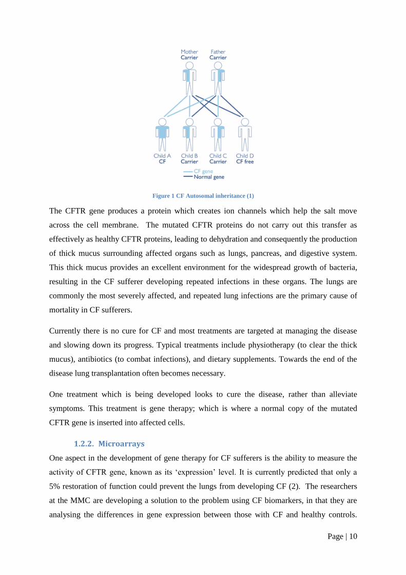
Figure 1 CF Autosomal inheritance (1) ................................................................................... 10
Figure 2 OGSA-DAI Generic Web Services (6) ..................................................................... 13
Figure 3 OGSA-DAI Security Levels ...................................................................................... 15
Figure 4 System Design for The Proposed System ................................................................. 17
Figure 5 The Structure of the Original Installers User Interface ............................................. 19
Figure 6 Container Choice Panel from the Original Installer .................................................. 20
Figure 7 Host Information Panel from the Original Installer .................................................. 21
Figure 8 Resource Deployment Panel from the Original Installer .......................................... 21
Figure 9 Resource Details Panel from the Original Installer ................................................... 21
Figure 10 Install Panel from the Original Installer .................................................................. 22
Figure 11 Finish Panel from the Original Installer .................................................................. 22
Figure 12 Updated Structure for the Installers User Interface ................................................. 26
Figure 13 The Original Schedule of Work .............................................................................. 30
Figure 14 Program and VM arguments needed to setup eclipse ............................................. 31
Figure 15 the Original Installers Source Files ......................................................................... 32
Figure 16 Changes to the Source Files .................................................................................... 33
Figure 17 Info element from Install.xml .................................................................................. 33
Figure 18 The panels element in Install.xml ............................................................................ 34
Figure 19 Panel number 1 from UserInputSpec.xml ............................................................... 34
Figure 20 The resource Deployment Panel defined in Figure 19 ............................................ 35
Figure 21 Deploy Resource Condition from Conditions.xml .................................................. 35
Figure 22 <pack> Element from install.xml ............................................................................ 36
Figure 23 Ant call from antActionSpec.xml ............................................................................ 37
Figure 24 Ant call to start the tomcat server ............................................................................ 38
Figure 25 Start Tomcat ant call StartTomcat.xml .................................................................... 38
Figure 26 Commands to Start Tomcat in UNIX ...................................................................... 39
Figure 27 Figure 19 XML used to add the MySQL files to a pack ......................................... 39
Figure 28 Ant Script to edit the MySQL configuration file..................................................... 39
Figure 29 A variable definition in an Ant Script ..................................................................... 40
Figure 30 Connection Details for the Java OGSA-DAI Client................................................ 41
Figure 31 SQL Statement in the Java OGSA-DAI Client ....................................................... 41
Figure 32 SQL Statement Execution in the Java OGSA-DAI Client ...................................... 42
Page | 8
Figure 33 Executing Java Program with an Ant Script............................................................ 42
Figure 34 Ant Script to Execute the Schema Script ................................................................ 43
Figure 35 The New Pack Decision on the Packs Panel ........................................................... 44
Figure 36 User Information panel XML definition ................................................................. 44
Figure 37 The User Input Panel Created For the Installer ....................................................... 45
Figure 38 The Decision Tree for the Installer .......................................................................... 45
Figure 39 Pack Selection Condition from Conditions.xml ...................................................... 46
Figure 40 Panel Condition to decide whether to display the userName Panel ........................ 46
Figure 41 The Ant Script to Deploy GT onto Tomcat ............................................................. 46
Figure 42 A Security Descriptor for OGSA-DAI Services ..................................................... 46
Figure 43 The Ant Commands to Secure the Services ............................................................ 47
Figure 44 Schedule of Work .................................................................................................... 53
Page | 9
1. Introduction
1.1. Overview
The aim of this project was to assist in the data management of the Gene Therapy clinical
trials in Cystic Fibrosis. The data produced from these trials is not only financially valuable
(the cost of running the experiments) but scientifically valuable, as it is hoped these results
could one day lead to a cure for Cystic Fibrosis. It is the value of this data that motivated this
project, as this project will lead the way to being able to set-up quick and reliable backup
systems to protect the trial data. Another major motivation for this project is that if the data
can be stored and managed it can then be shared and analysed over a distributed network of
institutions running similar studies. A system was developed to simplify the process of setting
servers to store the trial data. The system has a simple user interface to encourage its use by
the biologists running the trials. At the same time the system also addresses some of the
major concerns of system administrators, namely the security aspects of distributed data
storage.
1.2. Background
1.2.1. Cystic Fibrosis
Cystic Fibrosis (CF) is a hereditary disease that affects both the lungs and the digestive
system. It is the UK‘s most common life-threatening inherited disease affecting over 8,000
people. According to the Cystic Fibrosis Trust(1) the current average life expectancy for a CF
sufferer is around 31 years. CF is a genetic condition caused by a mutation in the Cystic
Fibrosis Transmembrane Conductance Regulator (CFTR) gene on chromosome 7. It is an
autosomal recessive disease, meaning that for a child to be born with CF it must inherit a pair
of defective genes from the parents. If only one defective gene is inherited then the child is
said to be a carrier of CF, but is otherwise completely healthy. Therefore, a child born to two
carriers has a 25% chance of inheriting both defective chromosomes and developing the
disease. The various permutations are illustrated in Figure 1. Around 1 in every 25 people in
the UK and 1 in 22 Europeans is a carrier of the mutated gene; carriers however show no
symptoms of the disease but can be tested for the mutation.
Page | 10
Figure 1 CF Autosomal inheritance (1)
The CFTR gene produces a protein which creates ion channels which help the salt move
across the cell membrane. The mutated CFTR proteins do not carry out this transfer as
effectively as healthy CFTR proteins, leading to dehydration and consequently the production
of thick mucus surrounding affected organs such as lungs, pancreas, and digestive system.
This thick mucus provides an excellent environment for the widespread growth of bacteria,
resulting in the CF sufferer developing repeated infections in these organs. The lungs are
commonly the most severely affected, and repeated lung infections are the primary cause of
mortality in CF sufferers.
Currently there is no cure for CF and most treatments are targeted at managing the disease
and slowing down its progress. Typical treatments include physiotherapy (to clear the thick
mucus), antibiotics (to combat infections), and dietary supplements. Towards the end of the
disease lung transplantation often becomes necessary.
One treatment which is being developed looks to cure the disease, rather than alleviate
symptoms. This treatment is gene therapy; which is where a normal copy of the mutated
CFTR gene is inserted into affected cells.
1.2.2. Microarrays
One aspect in the development of gene therapy for CF sufferers is the ability to measure the
activity of CFTR gene, known as its ‗expression‘ level. It is currently predicted that only a
5% restoration of function could prevent the lungs from developing CF (2). The researchers
at the MMC are developing a solution to the problem using CF biomarkers, in that they are
analysing the differences in gene expression between those with CF and healthy controls.
Page | 11
Biomarkers are identified as genes which are consistently, and significantly, differentially
expressed between groups of CF patients and controls. The efficacy of the gene therapy will
be monitored, as a time-course experiment, by measuring changes in the expression of these
biomarkers and of all other genes. It is hoped that gene therapy will bring the expression of
the biomarkers in CF sufferers closer to that seen in the healthy controls. The researchers
employ microarray technology to monitor this gene expression.
DNA microarrays are a new research tool for analysing the expression of thousands of genes
simultaneously. Microarrays are made up of thousands of gene specific probes arranged in a
known order on a solid background. As mentioned above microarrays are used to quantify
gene expressions in a cell, where a gene‘s expression is a measurement of its activity in the
nucleus. A gene is a strand of DNA and acts as the blueprint for protein production. First the
gene is transcribed to create messenger RNA (mRNA), the mRNA then produces proteins
which affect the surrounding cells, and the cells affect the body. To measure the gene
expression the amount of mRNA in the cell is measured as, this is thought to influence the
amount of proteins made, which in turn affects the body/cell.
Each probe on the array is made up of a large number of copies of a single, unique, DNA
strand. In a microarray experiment, mRNA is extracted from sample tissue, in this case either
CF or control, and tagged with a fluorescent dye. The tagged strands of mRNA are washed
over the microarray and each will bind specifically to one of the DNA probes on the array.
Once the binding has taken place the array is washed to remove any unbound mRNA. The
probes on the array are individually scanned with a laser, causing the bound mRNA to
fluoresce. By measuring and recording the intensity of the light emitted from each probe the
amount of mRNA bound to each probe can be quantified (the more bound mRNA the greater
the light intensity). This technique allows for the direct comparison of gene expressions
between CF patients and controls.
As the laser scans the microarray chip, the fluorescence is recorded using a photomultiplier
tube. The resulting output from the experiment is a TIFF image of the entire chip. In order for
useful biological analyses, software algorithms transform this image into an array of numbers
representing the average signal recorded for each probe. This array is called a gene
expression matrix and is the base for all further statistical investigations on the genes.
Page | 12
1.2.3. Real-time PCR
Another method of analysing gene expression is real-time PCR. Real time Polymerase Chain
Reaction (real-time PCR) is commonly used to confirm microarray results. PCR uses the
same principles of RNA to DNA binding as microarray analyses. The major difference
between the two processes is that while microarrays simultaneously analyse thousands of
gene expressions, real-time PCR concentrates on just one. Before undergoing real-time PCR,
mRNA must be reverse-transcribed to complementary DNA (cDNA). Once converted to
cDNA it is then amplified using DNA polymerase (an enzyme that replicates DNA). Once
amplified the resulting amount of DNA is measured, like in the microarray experiments the
DNA is tagged with a florescent marker, thus meaning the greater intensity of the
fluorescence the greater the amount of DNA. This process of amplification and measurement
is then iterated around 40 times and the results plotted on a graph. Using a number of controls
the exact rate of amplification can be calculated and then, using this value, the researchers
can extrapolate the original mRNA concentration in the sample, thus measuring the gene
expression in the cell.
1.2.4. Current Procedures
The Molecular Medicine Centre(2) is currently researching the use of gene therapy to aid in
the treatment of Cystic Fibrosis. The clinical trials currently running require the comparison
of gene expressions in cells of affected patients versus controls. The current process for the
analysis of gene expression in a single sample is listed below
1. Total RNA is extracted from the cells and the mRNA is separated
2. The mRNA is quality checked using an Agilent 2100 Bio analyser (3)
3. The mRNA is then amplified to become aRNA
4. The quality of the aRNA is again assessed, again using the 2100 Bio analyser
5. The aRNA is then used in a microarray experiment.
Once the results of the microarray experiment have been analysed, any genes shown to be
significantly differentially expressed between disease and control are selected and re-tested
using real-time PCR. In this process the first four steps are as above, then
5. The aRNA is reverse transcribed into cDNA
6. The quality of the cDNA is then assessed
7. The sample is used in the real-time PCR experiments
Page | 13
In these experiments, steps 2, 4, 5(in both microarray and real-time PCR) 6 and 7 all produce
data that needs to be easily managed, stored, and processed. Currently a system has been
developed by Rob Kitchen to manage the data output from these experiments(4). The current
system is a desktop application, which takes the data produced from the experiments and
stores it in a local database. This project aimed to simplify the process of backing up and
sharing data remotely. The information gathered in these trials is subject to statistical analysis
and it is anticipated that by increasing the sample size, the effect will be to produce more
statistically significant results. Extrapolating to the situation where, if the data were pooled
between multiple institutions, the effect on the significance of the results could be
tremendous. Distributed data would not only increase the sample size, but also normalise it,
as geographical anomalies could become apparent (for example, highlighting the differences
in the data analysis procedures at different institutions).
1.2.5. Technology
Open Grid Services Architecture Data Access and Integration (OGSA-DAI) is a middleware
product that allows data resources, such as relational or XML databases, to be accessed via
web services (5). The OGSA-DAI project started in 2002 and is ongoing; the project has
created 3 major releases so far.
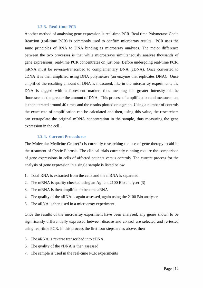
The first problem encountered when sharing data resources is how to give users access. One
way to do this is to expose the functionality of the data server in an application-specific web
service. The benefits are that using the web service approach gives a platform-neutral
solution and also provides a good security infrastructure. The problem arises when dealing
with multiple databases of multiple types (see A in Figure 2). The solution developed by the
OGSA-DAI team was to use generic, non-application-specific web services (see B Figure 2).
Figure 2 OGSA-DAI Generic Web Services (6)

Page | 14
OGSA-DAI not only provides a framework for exposing data resources on a grid it also
provides support for the following:
Data transformation.
Data can be delivered to clients or other OGSA-DAI web services, URLs, FTP
servers, GridFTP servers.
Information about resources such as schemas can be accessed by clients.
1.2.5.1. Security
One of the focuses of this project is the OGSA-DAI security. The default security model in
OGSA-DAI is based on the Grid Security Infrastructure and X.509 certificates. The X.509
certificates are used in authentication, ensuring the identity of a user. A certificate is an
electronic document which binds together a user‘s identity with a public key (a number used
in the encryption of information). Certificates are usually issued by a controlling body known
as a certificate authority (CA). The purpose of the CA issuing certificates is so that the
authenticity of the certificate is verified by a trusted third party, the CA. Once a user has a
certificate this can be used as part of a secure conversation where both ends of the
communication are verified before messages are passed between them. The public keys
associated with the certificates are also used as part of the encryption algorithms protecting
messages, which means only the intended party can decrypt the message.
Page | 15
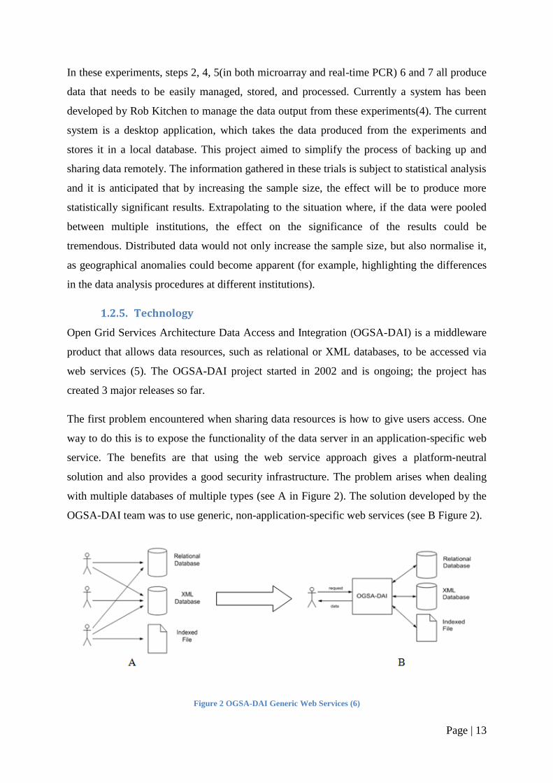
Figure 3 OGSA-DAI Security Levels
In OGSA-DAI, once the authentication is established there are two methods of
communication security as seen in Figure 3. Message level security encrypts the contents of
the message before it is transported, whilst transport level security encrypts the entire
conversation.
1.2.5.2. Container
OGSA-DAI requires a web service container. This is an environment inside a web server
where web services can be executed. OGSA-DAI supports two different containers: Globus
Toolkit (GT) and Apache Axis. The Globus Toolkit is a fundamental enabling technology for
the "Grid", letting people share computing power, databases, and other tools securely online
across corporate, institutional, and geographic boundaries without sacrificing local autonomy
(7). Apache Axis is an open source xml based web service framework. Both of these products
provide the framework for and execution of web services, which includes the implementation
of a SOAP server. SOAP is the messaging protocol at the heart of web services and concerns
sending XML over the internet using standard HTTP. The two containers can be deployed in
conjunction with an Apache Tomcat web server or the Globus Toolkit can be deployed as a
standalone container.
Page | 16
1.2.5.3. Database
OGSA-DAI is used to expose the access to resources over the internet. The resource in
question can be a multitude of things such as a file system or an XML database. In this report
the resource in question is a relational database.
Page | 17
2. Design
2.1. System Overview
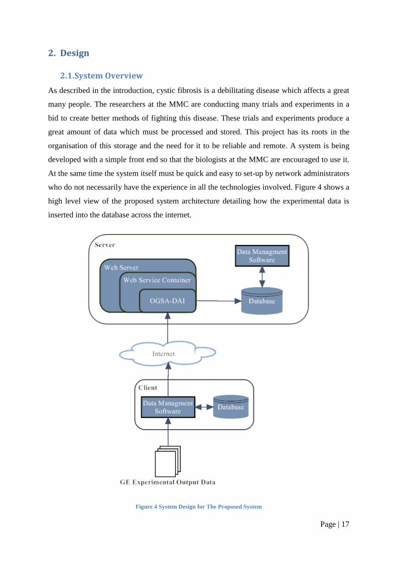
As described in the introduction, cystic fibrosis is a debilitating disease which affects a great
many people. The researchers at the MMC are conducting many trials and experiments in a
bid to create better methods of fighting this disease. These trials and experiments produce a
great amount of data which must be processed and stored. This project has its roots in the
organisation of this storage and the need for it to be reliable and remote. A system is being
developed with a simple front end so that the biologists at the MMC are encouraged to use it.
At the same time the system itself must be quick and easy to set-up by network administrators
who do not necessarily have the experience in all the technologies involved. Figure 4 shows a
high level view of the proposed system architecture detailing how the experimental data is
inserted into the database across the internet.
Figure 4 System Design for The Proposed System
Page | 18
2.1.1. Client
The client has been developed by Rob Kitchen (4) and is run on the scientist‘s local machine.
The client collects and manages the data from the experiments and produces a number of
SQL statements to commit this data to a remote database. These statements are then
transported to the web server on the remote server machine, using http protocols on the
internet, where they are processed and executed using OGSA-DAI and committed to the
database. The data management software in the client is the same data management software
on the server.
2.1.2. Server
The server consists of four components, firstly the web server which listens to a set port for
the communications from the client. Then the web service container which creates the
environment for the OGSA-DAI services to run. Thirdly the OGSA-DAI services‘
themselves which process the input from the client, so it can be passed to the final
component, the database.
2.2. Design Aims
Each of the components in the server has their own installation procedures, some of which
are very longwinded, using complicated command line arguments. Another drawback to
these procedures is the set-up required on the host machine. As well as having the Java
Development Environment (7) the machine must also have Apache Ant(8) and GNU
Compiler Collection(9). All this makes the set-up very unfriendly and time consuming for an
inexperienced user.
This project aims to simplify the set-up of a server. To do this the installation of the web
server, web service container, OGSA-DAI and database must be simplified and incorporated
into one easy-to-use installer. With this in mind the major design aims in this project are:
A complete installer to set-up a server
A simple user interface to facilitate the rapid deployment by non experienced users
The flexibility and security to satisfy the requirements set by system administrators
To achieve these aims this project intends to expand on an existing program developed as
part of the BEinGrid project (10). The program is a graphical user interface for the
installation of OGSA-DAI 3.0.
Page | 19
2.3. Current Installer
The current installer is produced using IzPack which is an open source software project
started in 2001. The software is a Java-based solution for packaging, distributing, and
deploying applications. The software generates a single JAR file that only requires the Java
runtime environment to operate, thus negating complex set-up on the host. This sole
dependence on the Java virtual machine also makes it easy to produce a cross-platform
compatible installer. This platform independence is of major benefit to the server set-up, as it
gives flexibility to the choice of machines used. Izpack also provides integration with apache
ant so is well suited for use in automating the OGSA-DAI deployment.
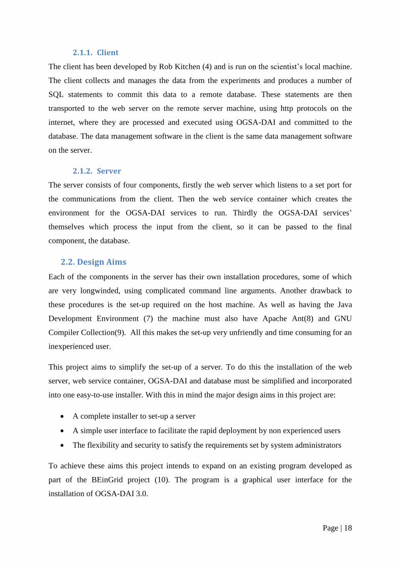
2.3.1. Structure of Current Installer
Figure 5 The Structure of the Original Installers User Interface
Figure 5 shows the structure of the current installer with each entity on the diagram
representing a panel presented to the user. The panels are split into two categories: those that
Page | 20
require user input and those that present installation information. The latter category will
remain unchanged and includes the welcome screen, the install screen and the finish screen.
There are five user input screens covering three areas of the setup:
Container choice
Web server setup
Resource deployment
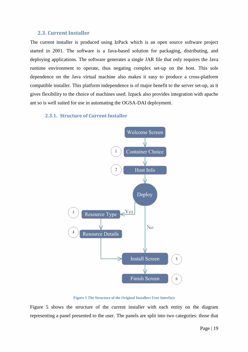
Figure 6 Container Choice Panel from the Original Installer
The first input screen is screen one in Figure 5 and is shown in Figure 6, the container
choice, where the user is asked to choose between the three distributions of OGSA-DAI
1. Globus
2. Tomcat with GT
3. Tomcat with Axis
Page | 21
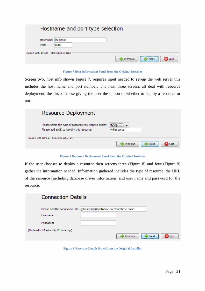
Figure 7 Host Information Panel from the Original Installer
Screen two, host info shown Figure 7, requires input needed to set-up the web server this
includes the host name and port number. The next three screens all deal with resource
deployment, the first of these giving the user the option of whether to deploy a resource or
not.
Figure 8 Resource Deployment Panel from the Original Installer
If the user chooses to deploy a resource then screens three (Figure 8) and four (Figure 9)
gather the information needed. Information gathered includes the type of resource, the URL
of the resource (including database driver information) and user name and password for the
resource.
Figure 9 Resource Details Panel from the Original Installer
Page | 22
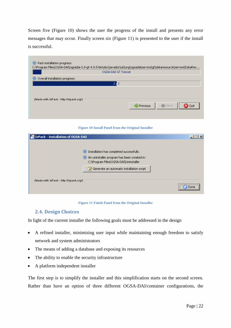
Screen five (Figure 10) shows the user the progress of the install and presents any error
messages that may occur. Finally screen six (Figure 11) is presented to the user if the install
is successful.
Figure 10 Install Panel from the Original Installer
Figure 11 Finish Panel from the Original Installer
2.4. Design Choices
In light of the current installer the following goals must be addressed in the design
A refined installer, minimising user input while maintaining enough freedom to satisfy
network and system administrators
The means of adding a database and exposing its resources
The ability to enable the security infrastructure
A platform independent installer
The first step is to simplify the installer and this simplification starts on the second screen.
Rather than have an option of three different OGSA-DAI/container configurations, the
Page | 23
container best suited to this project will be chosen and this will be the one presented to the
user.
2.4.1. Refining Installer
2.4.1.1. Container Choice
2.4.1.1.1. Web server
The first aspect in choosing which OGSA-DAI set-up is right for this project is to choose
which web server to use. There are two options
1. Apache Tomcat
2. Globus
The Globus web server is part of the Globus Toolkit and has one distinct advantage over the
Tomcat option in that it is both the web server and the web service container. It being the
complete package makes this a smaller option but only by about 10 mega bytes. Another
major advantage to the Globus option is that OGSA-DAI was developed with the Globus
Toolkit in mind. OGSA-DAI is in fact an off shoot of the Globus project.
The major drawback to using Globus as the web server is also the main selling point for
Tomcat and that is brand power. Outside the grid world Globus is not very well known
whereas Tomcat is synonymous with web servers in both the academic and business worlds.
This familiarity will work as a major benefit when presenting the installer to system and
network administrators. Another major benefit to Tomcat‘s popularity is that as an open
source product, the more use of the system, the more likely bugs will be spotted and a
solution devised. This means Tomcat is a very stable system which again makes it a very
popular choice. Finally one of the major reasons why Tomcat was chosen for this project is
its compatibility with operating systems. Tomcat is supplied with a number of features which
aid in its deployment into an operating system, the main one of these is that the start up
scripts also set the environment variables, unlike Globus which fails if the environment has
not been set-up. One further feature of Tomcat is its easy integration with operating systems
start up procedures which means it can be set to automatically start up when the system is
initialised.
Page | 24
2.4.1.1.2. Web Service Container
Having chosen Tomcat as the web server of choice the next decision is what web service
container to deploy inside of Tomcat. There are again two options
1. Globus Toolkit
2. Apache Axis
The Globus Toolkit is the larger of the two installations but only by 20 megabytes. As stated
in 2.4.1.1.1 above, OGSA-DAI and Globus are high compatible as OGSA-DAI has been
developed with Globus in mind. There is also extensive documentation available from the
OGSA-DAI project detailing the set-up and usage of the Globus Toolkit with Tomcat.
Axis is developed by the Apache Software Foundation and as such is extremely compatible
with Tomcat. Not only does the fact that Tomcat and Axis are developed by the same people
lead to compatibly and stability, it also gives great benefit to the community and therefore the
support that can be offered. However in this case it is the support that made the decision
between the containers a lot easier. Whereas there is plenty of support available on the web
for the integration of Axis into Tomcat, there is not that same level of support for the
integration of OGSA-DAI into Axis. The OGSA-DAI Axis documentation does not cover the
set-up of security. Given that security is one of the aims of the project the natural decision is
to use the Globus Toolkit as the web service container.
2.4.2. Database
The second major design decision is the inclusion of a local database install into the set-up.
The database is one of the most critical aspects in this system as this is where the data will
eventually be stored. Of the many different database systems available, both commercially
and freely, the MySQL database server was chosen. The reason for the choice of MySQL is
that it is the system currently in use at the MMC(2) with Rob Kitchen‘s client(4). Another
aspect in the addition of a local database is the need to deploy a database matching a set
schema. The schema for this project is again provided from the current working system
developed by Rob Kitchen. The schema sets out the format of the tables as well as the access
rights for users. The schema in this project defines two databases; the first is an
administrative database for user account management. The second is an individual database
for the user, containing the tables required to store the data from the experiments. The first
database is for administrative users and as such requires higher level access rights. This
Page | 25
means two resources will need to be deployed, one for the user and one for the database
administrator.
One feature in the implementation of this schema is the ease by which it can be updated or
changed. Consideration is given to ensuring the schema definition is separated from the main
installation so it can be readily changed or replaced.
2.4.2.1. New User Interface of the Installer
As discussed above the first design choice was to simplify the installation procedure by
eliminating the choice of OGSA-DAI distributions. The next major design change to the
installer is the addition of a database installation. Due to this addition the first decision now
presented to the user is whether to include the installation of a local database or to proceed
with either no resource or a remote resource.
Page | 26
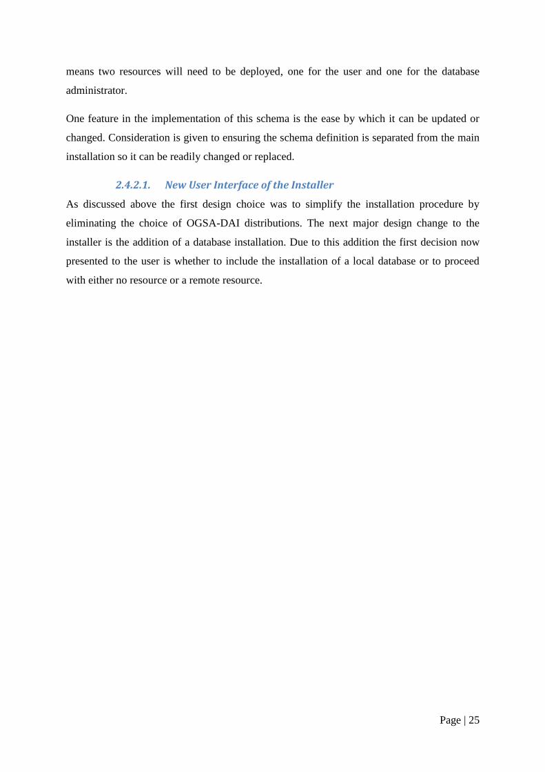
Figure 12 Updated Structure for the Installers User Interface
As can be seen from Figure 12 the installer has been stream-lined considerably when the user
chooses to deploy a local database. Instead of being presented with four screens the user now
is presented with only two. The first screen is the same as before, taking the host information
of hostname and port number but the second screen is new, taking the username, password
and a name for the resource. The reason this side of the installer has such minimal input is
due to the fact that many variables are hard wired into the program. The hard coded variables
all concern the database details, which can be set as the local database and its set-up is
known. The left hand fork of the installer remains relatively unchanged to offer the flexibility
of the remote resource deployment. The right hand fork is streamlined with the minimum
user input as this is expected to be the default route for new users.
Page | 27
2.4.3. Security
The final design decision is what level of security to enable with the installer. As is
mentioned in 1.2.5.1 above there are two possible levels of security
Message Level Security
Transport Level Security
Message Level Security (MLS) is a feature rich protocol supporting both GSI Secure
Message and GSI Secure Conversation. Advantages include that because the encryption is
done at message level separate portions of messages can be encrypted. This means if
messages contain a mixture of sensitive and non-sensitive information only the sensitive
information needs to be encrypted. Another advantage is the fact the MLS has a good
integration with web service standards. However due to the fact that it is relatively new MLS
has some performance issues which could lead to the slow transfer of data.
Transport Level Security (TLS) is used by default in the Globus Toolkit and has been a
standard for years. Given that TLS has been around in various forms since 1994 its current
incarnation has relatively good performance. Due to the large quantities of data being
transferred through the server, performance will become an issue and therefore TLS was
considered to be a better option.
Another OGSA-DAI security option is whether to enable integrity or privacy. Integrity
guarantees that messages have not been altered by third parties, whilst privacy guarantees
messages have not been altered by third parties and additionally encrypts the messages so that
it cannot be read by third parties. Although enabling integrity would mean a high
performance, the risk that third parties will be able to read the contents of the messages
means it is unfit for this project. As there is sensitive medical information being transferred
through the server, the privacy protection level must be enabled to encrypt all aspects of the
message transfers, thus securing the message from third parties.
A further aspect of the security set-up is authentication, for this aspect there is no choice
involved as the Globus Toolkit only supports the X.509 standard. This means using
certificates to identify users.
Lastly with respect to the security infrastructure is the access to the database. This was only
of concern when implementing a local database. The database is installed with a root user
account; this account originally has no password and total access and control over all
Page | 28
databases. This is account can only be accessed by the local host but still must still be secured
with a password. It was decided to hardwire the password as only the database administrator
would need to know it, not the users installing the system. The other issue with the database
is user access for the deployed resource; this is controlled by the schema set by Rob Kitchen.
In the database schema the access rights for the database and also individual tables are set.
2.4.4. Platform Independence
The final step to consider in the design of the system was keeping the platform independence.
This issue was dealt with in the implementation phase of the project. Any additional
functionality added to the installer must be implemented in such a way that it can run on
multiple platforms. One of the reasons the Izpack software was chosen for this project is its
cross-platform abilities. Izpack can determine the operating system it is being run on and
therefore any installation process can be tailored for multiple operating systems.
2.5. Work plan
2.5.1. Methodology
This project is going to utilise an agile methodology inspired by extreme programming (XP)
(11). The reason it is only inspired by XP is that not all the aspects of XP apply or can apply
to a project of this size. The main reasons for choosing the agile methodology are
1. The primary aim of the project is to simplify the installer; once this is done the next steps
are adding functionality. Using the XP method the primary objective can be designed,
implemented, and tested before work starts on the extra features. Early feedback will be
necessary, regarding whether the installer performs appropriately and if the correct level
of complexity has been achieved. It will also be necessary to monitor the level of
transparency of the installer so as to satisfy network and system administrators. If a more
unified approach was used the system would not be available to the user until the end of
the project, at which point changes to the basic implementation would be extremely
difficult.
2. Due to the fact that this is a software evolution, it will be necessary to maintain a regime
of continuous testing to ensure new additions to the code don‘t compromise the integrity
of the existing system.
3. Another reason for this agile approach is that the constant design, implementation, and
testing will fit very well into the work plan. It will be a very realistic goal to produce
Page | 29
constant releases which can then be evaluated at the meeting with supervisors and
contributors.
Areas where the methodology diverges from XP will be in the onsite customer and pair
programming. To solve the problem of not having an onsite customer, regular meetings will
be arranged to review each major development. As for pair programming given this is a solo
project and not a large project it is unfeasible. The effectiveness of this methodology will be
evaluated in Section 4.1 below.
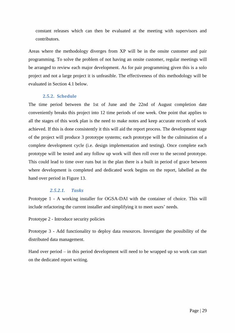
2.5.2. Schedule
The time period between the 1st of June and the 22nd of August completion date
conveniently breaks this project into 12 time periods of one week. One point that applies to
all the stages of this work plan is the need to make notes and keep accurate records of work
achieved. If this is done consistently it this will aid the report process. The development stage
of the project will produce 3 prototype systems; each prototype will be the culmination of a
complete development cycle (i.e. design implementation and testing). Once complete each
prototype will be tested and any follow up work will then roll over to the second prototype.
This could lead to time over runs but in the plan there is a built in period of grace between
where development is completed and dedicated work begins on the report, labelled as the
hand over period in Figure 13.
2.5.2.1. Tasks
Prototype 1 - A working installer for OGSA-DAI with the container of choice. This will
include refactoring the current installer and simplifying it to meet users‘ needs.
Prototype 2 - Introduce security policies
Prototype 3 - Add functionality to deploy data resources. Investigate the possibility of the
distributed data management.
Hand over period – in this period development will need to be wrapped up so work can start
on the dedicated report writing.
Page | 30
The development period for each prototype is 2 weeks. It was reasoned that this is a generous
enough time period for each deliverable while also keeping the project moving forward at a
good pace.
Figure 13 The Original Schedule of Work
1 2 3 4 5 6 7 8 9 10 11 12
Set-up
Prototype 1
Prototype 2
Prototype 3
Hand Over Period
Dedicated Write Up Time
Revise Report in Light of Feedback
Proof Read/Hand In
Dead Line for Submitting Drafts on which
Supervisors May Give Feedback
Submit Draft Report
Structure to Supervisors
Page | 31
3. Implementation
3.1. Development Environment
The development environment used for the implementation of this project was a virtual
machine using Microsoft Virtual PC 2007 (12). A virtual machine is a software
implementation of a computer that executes programs like a real computer. Once the
operating system had been installed onto the virtual system there are a number of
environment variables that must be set-up. The first and most important aspect of the system
setup is that of the Java development kit (JDK) (7). This kit includes the Java runtime
environment (JRE) which is required to run the Izpack software as well as other Java
programs. The JDK also includes a Java compiler which is needed to develop the Java based
OGSA-DAI clients.
The second aspect of environment setup is to install the Izpack software. This software is
provided in a jar file which must be unpacked to the working directory. Once unpacked the
Izpack compiler must be set-up for use. In this project it was decided to use the compiler
alongside the eclipse (13) integrated development environment (IDE) rather than set the
operating systems class path and use the command line for compiling. By doing this, all the
development such as XML and Java editing as well as the compiling could be carried out
within the eclipse environment.
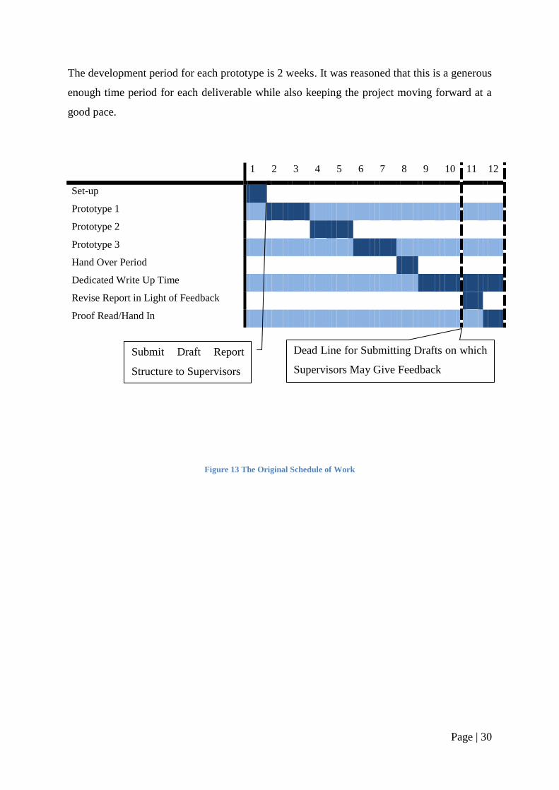
To setup the compile environment in eclipse the run dialog for the project must be created.
Firstly the Izpack compiler must be added as the main class in the project. The program
arguments must then be set; these are the settings used by the compiler to produce the
installer and are shown in Figure 14.
Figure 14 Program and VM arguments needed to setup eclipse
Page | 32
The first argument is the location of the main definition file of the installer, in this case
install.xml, the –b indicates that this is the base path to be used for the installer. The second
argument –o specifies that the next variable is the destination path for the program including
the file name for the installer jar file. The final piece of eclipse setup is the VM argument;
this is set to the location of the Izpack base directory.
The final aspect of setup needed on the test machine is the installation of the apache ant
software. This is needed for manually testing the ant scripts created for the installer. Apache
Ant is distributed as an archive which must be unpacked and its destination directory must be
added to the class path by creating an environment variable ANT_HOME.
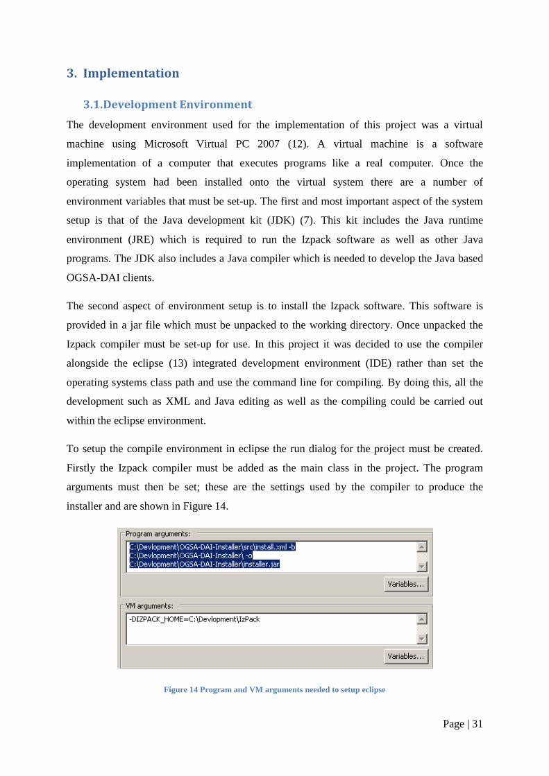
3.2. Initial Reverse engineer
Figure 15 the Original Installers Source Files
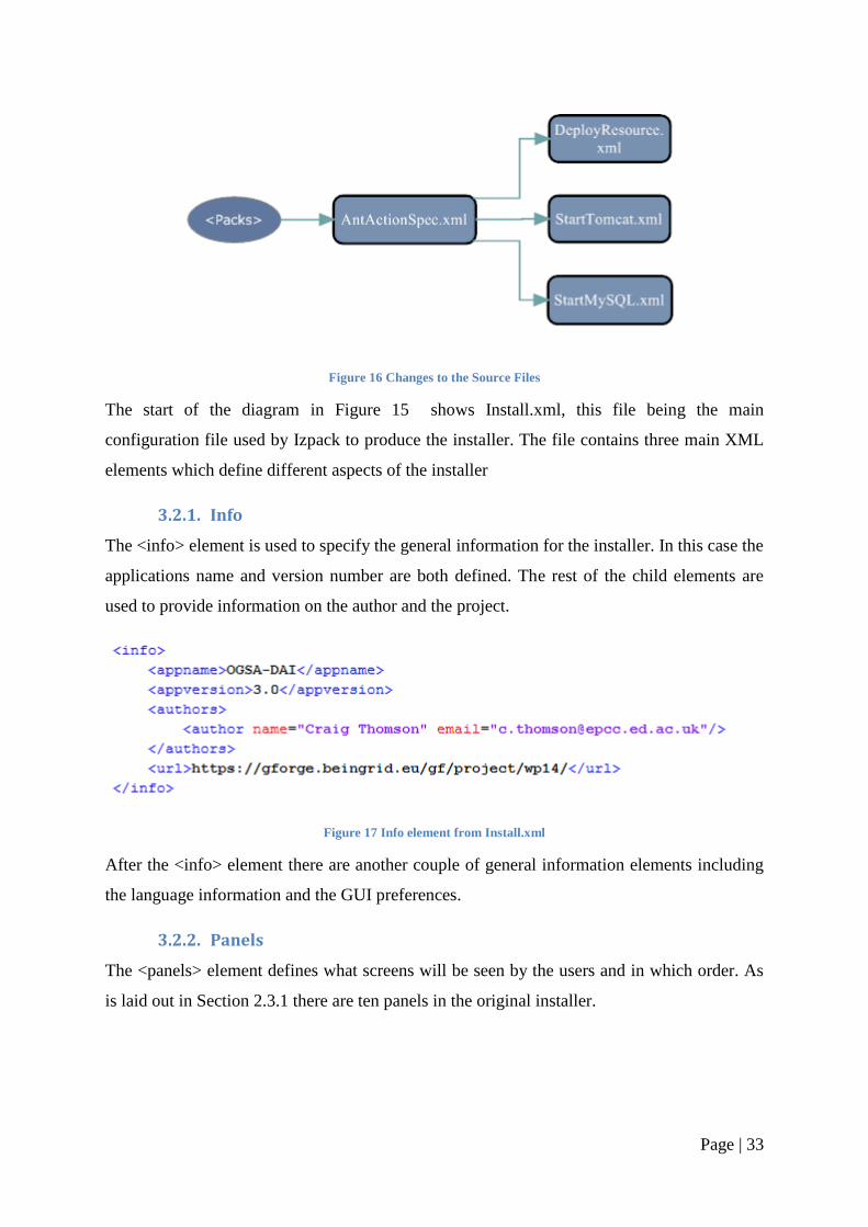
The diagram in Figure 15 shows the original source files as well as some key XML elements,
shown in the ovals. The main development process will be to edit the existing source files to
configure the changes discussed in Section 2.4. This refinement of the current source files
will be discussed in Section 3.3 below. One addition to the source files, shown in Figure 16,
is the StartMySQL.xml file added to configure the local database install. This development is
addressed in Section 3.4.
Page | 33
Figure 16 Changes to the Source Files
The start of the diagram in Figure 15 shows Install.xml, this file being the main
configuration file used by Izpack to produce the installer. The file contains three main XML
elements which define different aspects of the installer
3.2.1. Info
The <info> element is used to specify the general information for the installer. In this case the
applications name and version number are both defined. The rest of the child elements are
used to provide information on the author and the project.
Figure 17 Info element from Install.xml
After the <info> element there are another couple of general information elements including
the language information and the GUI preferences.
3.2.2. Panels
The <panels> element defines what screens will be seen by the users and in which order. As
is laid out in Section 2.3.1 there are ten panels in the original installer.
Page | 34
Figure 18 The panels element in Install.xml
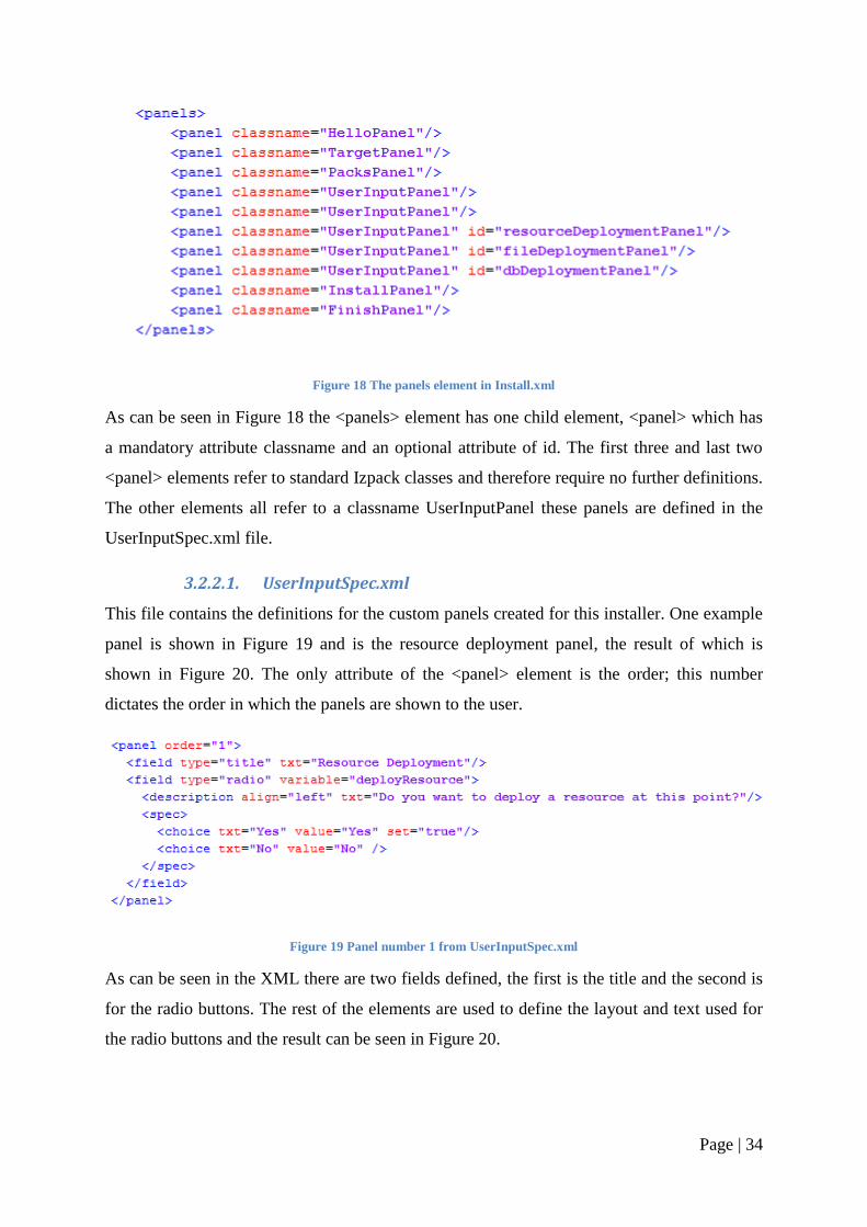
As can be seen in Figure 18 the <panels> element has one child element, <panel> which has
a mandatory attribute classname and an optional attribute of id. The first three and last two
<panel> elements refer to standard Izpack classes and therefore require no further definitions.
The other elements all refer to a classname UserInputPanel these panels are defined in the
UserInputSpec.xml file.
3.2.2.1. UserInputSpec.xml
This file contains the definitions for the custom panels created for this installer. One example
panel is shown in Figure 19 and is the resource deployment panel, the result of which is
shown in Figure 20. The only attribute of the <panel> element is the order; this number
dictates the order in which the panels are shown to the user.
Figure 19 Panel number 1 from UserInputSpec.xml
As can be seen in the XML there are two fields defined, the first is the title and the second is
for the radio buttons. The rest of the elements are used to define the layout and text used for
the radio buttons and the result can be seen in Figure 20.
Page | 35
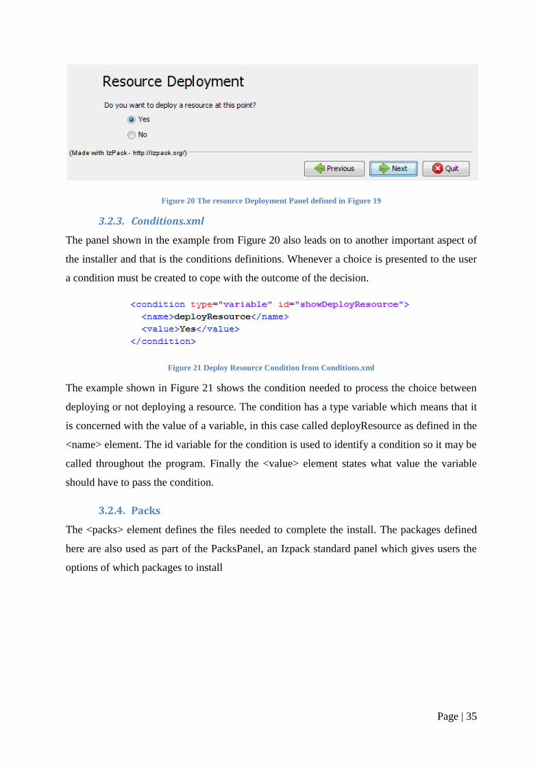
Figure 20 The resource Deployment Panel defined in Figure 19
3.2.3. Conditions.xml
The panel shown in the example from Figure 20 also leads on to another important aspect of
the installer and that is the conditions definitions. Whenever a choice is presented to the user
a condition must be created to cope with the outcome of the decision.
Figure 21 Deploy Resource Condition from Conditions.xml
The example shown in Figure 21 shows the condition needed to process the choice between
deploying or not deploying a resource. The condition has a type variable which means that it
is concerned with the value of a variable, in this case called deployResource as defined in the
<name> element. The id variable for the condition is used to identify a condition so it may be
called throughout the program. Finally the <value> element states what value the variable
should have to pass the condition.
3.2.4. Packs
The <packs> element defines the files needed to complete the install. The packages defined
here are also used as part of the PacksPanel, an Izpack standard panel which gives users the
options of which packages to install
Page | 36
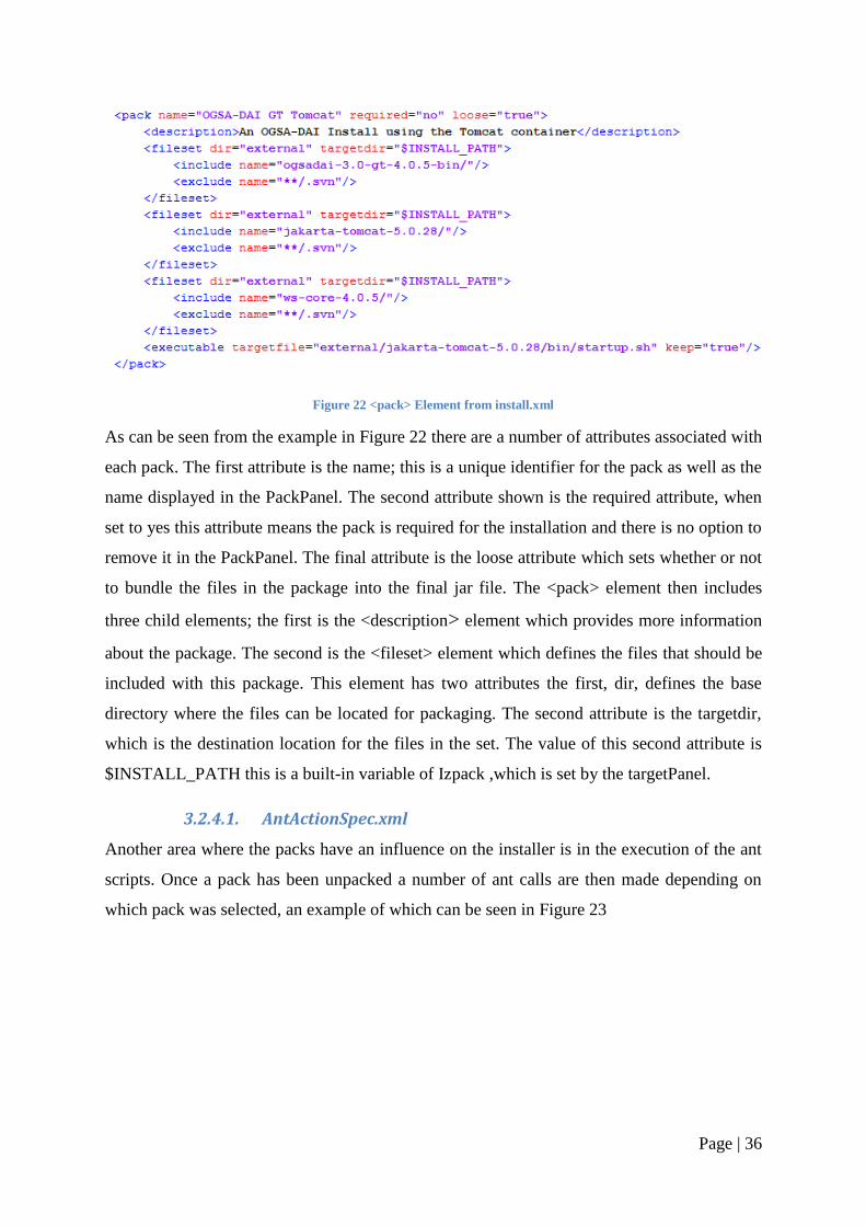
Figure 22 <pack> Element from install.xml
As can be seen from the example in Figure 22 there are a number of attributes associated with
each pack. The first attribute is the name; this is a unique identifier for the pack as well as the
name displayed in the PackPanel. The second attribute shown is the required attribute, when
set to yes this attribute means the pack is required for the installation and there is no option to
remove it in the PackPanel. The final attribute is the loose attribute which sets whether or not
to bundle the files in the package into the final jar file. The <pack> element then includes
three child elements; the first is the <description> element which provides more information
about the package. The second is the <fileset> element which defines the files that should be
included with this package. This element has two attributes the first, dir, defines the base
directory where the files can be located for packaging. The second attribute is the targetdir,
which is the destination location for the files in the set. The value of this second attribute is
$INSTALL_PATH this is a built-in variable of Izpack ,which is set by the targetPanel.
3.2.4.1. AntActionSpec.xml
Another area where the packs have an influence on the installer is in the execution of the ant
scripts. Once a pack has been unpacked a number of ant calls are then made depending on
which pack was selected, an example of which can be seen in Figure 23
Page | 37
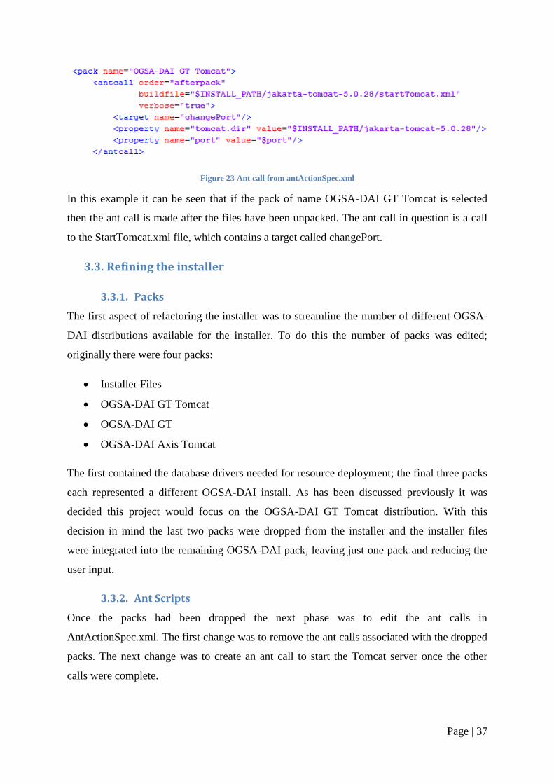
Figure 23 Ant call from antActionSpec.xml
In this example it can be seen that if the pack of name OGSA-DAI GT Tomcat is selected
then the ant call is made after the files have been unpacked. The ant call in question is a call
to the StartTomcat.xml file, which contains a target called changePort.
3.3. Refining the installer
3.3.1. Packs
The first aspect of refactoring the installer was to streamline the number of different OGSA-
DAI distributions available for the installer. To do this the number of packs was edited;
originally there were four packs:
Installer Files
OGSA-DAI GT Tomcat
OGSA-DAI GT
OGSA-DAI Axis Tomcat
The first contained the database drivers needed for resource deployment; the final three packs
each represented a different OGSA-DAI install. As has been discussed previously it was
decided this project would focus on the OGSA-DAI GT Tomcat distribution. With this
decision in mind the last two packs were dropped from the installer and the installer files
were integrated into the remaining OGSA-DAI pack, leaving just one pack and reducing the
user input.
3.3.2. Ant Scripts
Once the packs had been dropped the next phase was to edit the ant calls in
AntActionSpec.xml. The first change was to remove the ant calls associated with the dropped
packs. The next change was to create an ant call to start the Tomcat server once the other
calls were complete.
Page | 38
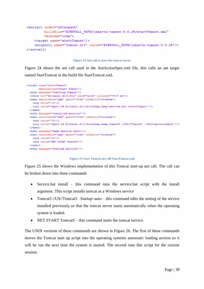
Figure 24 Ant call to start the tomcat server
Figure 24 shows the ant call used in the AntActionSpec.xml file, this calls an ant target
named StartTomcat in the build file StartTomcat.xml.
Figure 25 Start Tomcat ant call StartTomcat.xml
Figure 25 shows the Windows implementation of this Tomcat start-up ant call. The call can
be broken down into three commands
Service.bat install – this command runs the service.bat script with the install
argument. This script installs tomcat as a Windows service
Tomcat5 //US//Tomcat5 –Startup=auto – this command edits the setting of the service
installed previously so that the tomcat server starts automatically when the operating
system is loaded.
NET START Tomcat5 – this command starts the tomcat service.
The UNIX versions of these commands are shown in Figure 26. The first of these commands
moves the Tomcat start up script into the operating systems automatic loading section so it
will be run the next time the system is started. The second runs this script for the current
session.
Page | 39
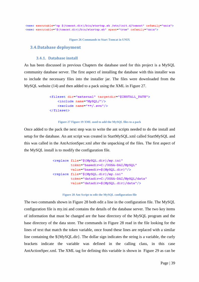
Figure 26 Commands to Start Tomcat in UNIX
3.4. Database deployment
3.4.1. Database install
As has been discussed in previous Chapters the database used for this project is a MySQL
community database server. The first aspect of installing the database with this installer was
to include the necessary files into the installer jar. The files were downloaded from the
MySQL website (14) and then added to a pack using the XML in Figure 27.
Figure 27 Figure 19 XML used to add the MySQL files to a pack
Once added to the pack the next step was to write the ant scripts needed to do the install and
setup for the database. An ant script was created in StartMySQL.xml called StartMySQL and
this was called in the AntActionSpec.xml after the unpacking of the files. The first aspect of
the MySQL install is to modify the configuration file.
Figure 28 Ant Script to edit the MySQL configuration file
The two commands shown in Figure 28 both edit a line in the configuration file. The MySQL
configuration file is my.ini and contains the details of the database server. The two key items
of information that must be changed are the base directory of the MySQL program and the
base directory of the data store. The commands in Figure 28 read in the file looking for the
lines of text that match the token variable, once found these lines are replaced with a similar
line containing the ${MySQL.dir}. The dollar sign indicates the string is a variable, the curly
brackets indicate the variable was defined in the calling class, in this case
AntActionSpec.xml. The XML tag for defining this variable is shown in Figure 29 as can be
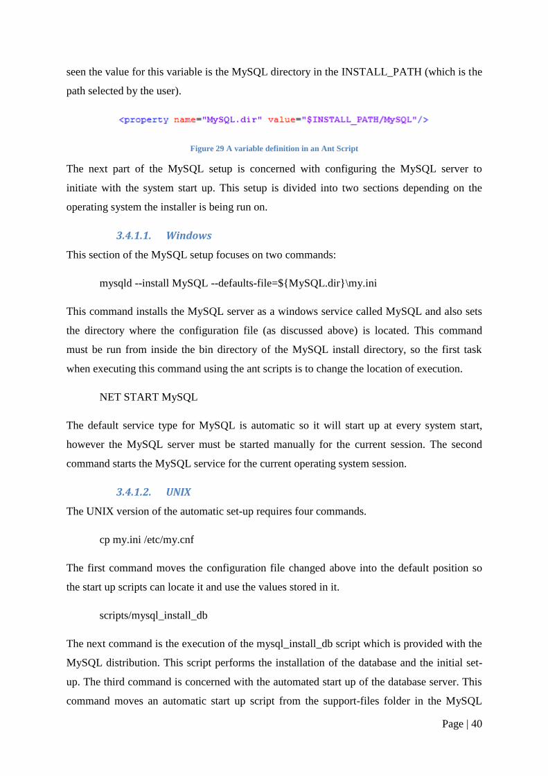
Page | 40
seen the value for this variable is the MySQL directory in the INSTALL_PATH (which is the
path selected by the user).
Figure 29 A variable definition in an Ant Script
The next part of the MySQL setup is concerned with configuring the MySQL server to
initiate with the system start up. This setup is divided into two sections depending on the
operating system the installer is being run on.
3.4.1.1. Windows
This section of the MySQL setup focuses on two commands:
mysqld --install MySQL --defaults-file=${MySQL.dir}\my.ini
This command installs the MySQL server as a windows service called MySQL and also sets
the directory where the configuration file (as discussed above) is located. This command
must be run from inside the bin directory of the MySQL install directory, so the first task
when executing this command using the ant scripts is to change the location of execution.
NET START MySQL
The default service type for MySQL is automatic so it will start up at every system start,
however the MySQL server must be started manually for the current session. The second
command starts the MySQL service for the current operating system session.
3.4.1.2. UNIX
The UNIX version of the automatic set-up requires four commands.
cp my.ini /etc/my.cnf
The first command moves the configuration file changed above into the default position so
the start up scripts can locate it and use the values stored in it.
scripts/mysql_install_db
The next command is the execution of the mysql_install_db script which is provided with the
MySQL distribution. This script performs the installation of the database and the initial set-
up. The third command is concerned with the automated start up of the database server. This
command moves an automatic start up script from the support-files folder in the MySQL
Page | 41
distribution to the init.d folder, where the operating systems automated start up scripts are
stored.
cp /support-files/mysql.server /etc/init.d/mysql
The final command starts the database for the current operating system session. All these
commands need to be run in the main folder of the MySQL distribution.
bin/mysqld_safe &
3.4.2. Schema Deployment
3.4.2.1. Java Deployment
3.4.2.1.1. Java Client
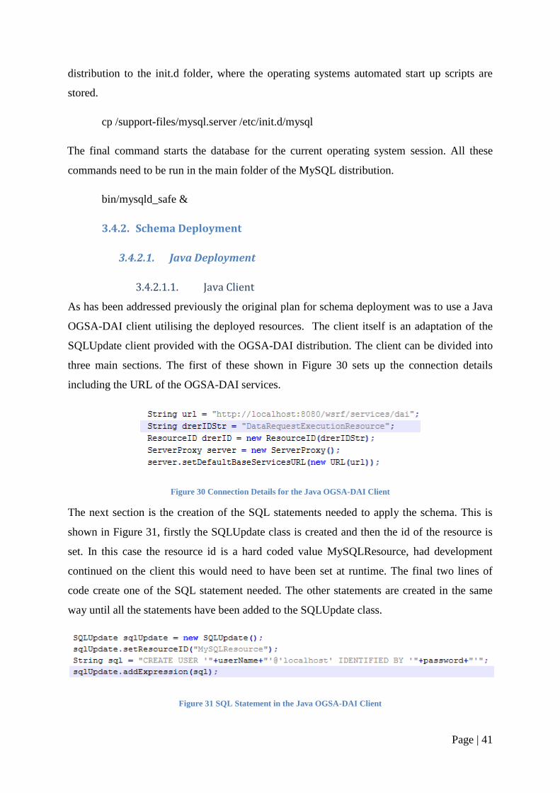
As has been addressed previously the original plan for schema deployment was to use a Java
OGSA-DAI client utilising the deployed resources. The client itself is an adaptation of the
SQLUpdate client provided with the OGSA-DAI distribution. The client can be divided into
three main sections. The first of these shown in Figure 30 sets up the connection details
including the URL of the OGSA-DAI services.
Figure 30 Connection Details for the Java OGSA-DAI Client
The next section is the creation of the SQL statements needed to apply the schema. This is
shown in Figure 31, firstly the SQLUpdate class is created and then the id of the resource is
set. In this case the resource id is a hard coded value MySQLResource, had development
continued on the client this would need to have been set at runtime. The final two lines of
code create one of the SQL statement needed. The other statements are created in the same
way until all the statements have been added to the SQLUpdate class.
Figure 31 SQL Statement in the Java OGSA-DAI Client
Page | 42
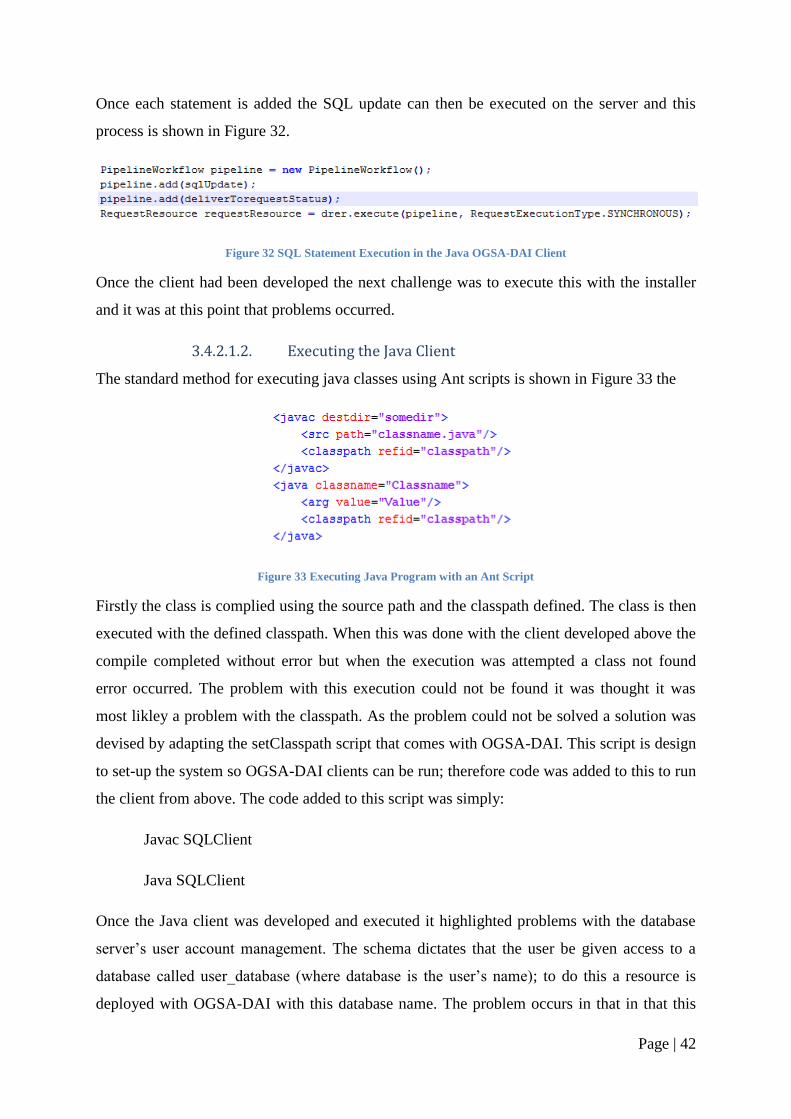
Once each statement is added the SQL update can then be executed on the server and this
process is shown in Figure 32.
Figure 32 SQL Statement Execution in the Java OGSA-DAI Client
Once the client had been developed the next challenge was to execute this with the installer
and it was at this point that problems occurred.
3.4.2.1.2. Executing the Java Client
The standard method for executing java classes using Ant scripts is shown in Figure 33 the
Figure 33 Executing Java Program with an Ant Script
Firstly the class is complied using the source path and the classpath defined. The class is then
executed with the defined classpath. When this was done with the client developed above the
compile completed without error but when the execution was attempted a class not found
error occurred. The problem with this execution could not be found it was thought it was
most likley a problem with the classpath. As the problem could not be solved a solution was
devised by adapting the setClasspath script that comes with OGSA-DAI. This script is design
to set-up the system so OGSA-DAI clients can be run; therefore code was added to this to run
the client from above. The code added to this script was simply:
Javac SQLClient
Java SQLClient
Once the Java client was developed and executed it highlighted problems with the database
server‘s user account management. The schema dictates that the user be given access to a
database called user_database (where database is the user‘s name); to do this a resource is
deployed with OGSA-DAI with this database name. The problem occurs in that in that this
Page | 43
resource cannot be used to create the user_database on the database server. The solution for
this is to have a separate resource deployed to standard database from which the user
database can be created. This second resource must have the correct privileges to create
databases and user accounts; it was decided to use the default MySQL root account. MySQL
is installed with one standard root account available for use from the local host. The OGSA-
DAI resource required a second root account with the same privileges but accessible from a
non local host. There is no non SQL method for creating this second user therefore the SQL
statement must be executed in MySQL. It was decided that if scripts needed to be written to
execute one SQL statement, they should be written to execute all the SQL statements. This
decision meant the Java client was no longer needed.
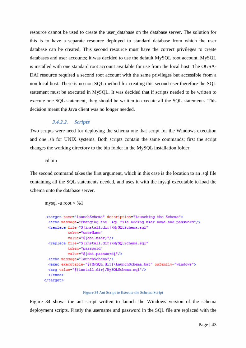
3.4.2.2. Scripts
Two scripts were need for deploying the schema one .bat script for the Windows execution
and one .sh for UNIX systems. Both scripts contain the same commands; first the script
changes the working directory to the bin folder in the MySQL installation folder.
cd bin
The second command takes the first argument, which in this case is the location to an .sql file
containing all the SQL statements needed, and uses it with the mysql executable to load the
schema onto the database server.
mysql -u root < %1
Figure 34 Ant Script to Execute the Schema Script
Figure 34 shows the ant script written to launch the Windows version of the schema
deployment scripts. Firstly the username and password in the SQL file are replaced with the
Page | 44
values provided by the user in the installation. The LaunchSchema.bat script file can then be
executed with the destination of the SQL file as a command line argument.
3.4.3. New User interface
It was decided with the addition of the local database install to have two package options; one
which would include the local database files and one that would not. This was done so the
packs panel would become a decision point for the user; pack one would lead to the new
implementation including the local database, pack two would keep the old functionality of the
remote database deployment. This decision panel can be seen in Error! Reference source
ot found.
Figure 35 The New Pack Decision on the Packs Panel
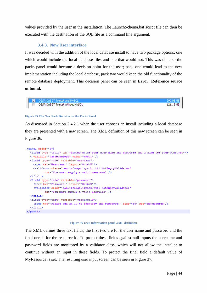
As discussed in Section 2.4.2.1 when the user chooses an install including a local database
they are presented with a new screen. The XML definition of this new screen can be seen in
Figure 36.
Figure 36 User Information panel XML definition
The XML defines three text fields, the first two are for the user name and password and the
final one is for the resource id. To protect these fields against null inputs the username and
password fields are monitored by a validator class, which will not allow the installer to
continue without an input in these fields. To protect the final field a default value of
MyResource is set. The resulting user input screen can be seen in Figure 37.
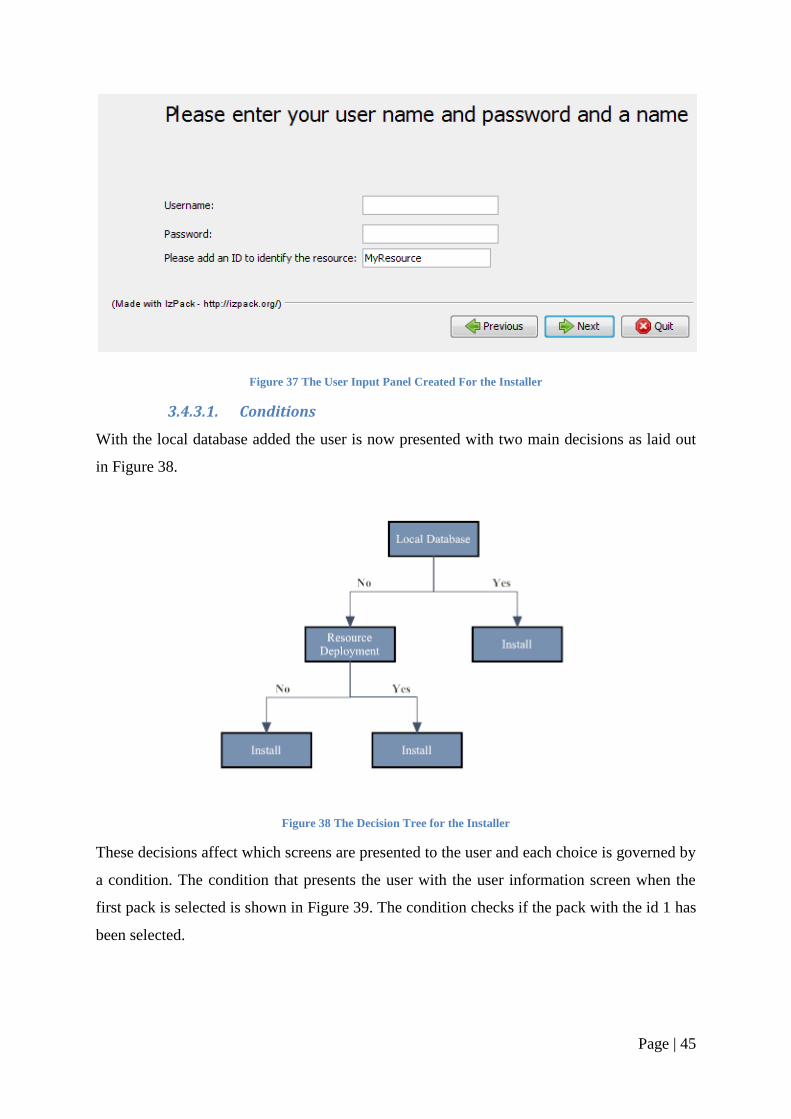
Page | 45
Figure 37 The User Input Panel Created For the Installer
3.4.3.1. Conditions
With the local database added the user is now presented with two main decisions as laid out
in Figure 38.
Figure 38 The Decision Tree for the Installer
These decisions affect which screens are presented to the user and each choice is governed by
a condition. The condition that presents the user with the user information screen when the
first pack is selected is shown in Figure 39. The condition checks if the pack with the id 1 has
been selected.
Page | 46
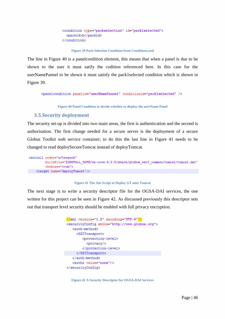
Figure 39 Pack Selection Condition from Conditions.xml
The line in Figure 40 is a panelcondition element, this means that when a panel is due to be
shown to the user it must satify the codition referenced here. In this case for the
userNamePannel to be shown it must satisfy the pack1selected condition which is shown in
Figure 39.
Figure 40 Panel Condition to decide whether to display the userName Panel
3.5. Security deployment
The security set-up is divided into two main areas, the first is authentication and the second is
authorisation. The first change needed for a secure server is the deployment of a secure
Globus Toolkit web service container; to do this the last line in Figure 41 needs to be
changed to read deploySecureTomcat instead of deployTomcat.
Figure 41 The Ant Script to Deploy GT onto Tomcat
The next stage is to write a security descriptor file for the OGSA-DAI services, the one
written for this project can be seen in Figure 42. As discussed previously this descriptor sets
out that transport level security should be enabled with full privacy encryption.
Figure 42 A Security Descriptor for OGSA-DAI Services
Page | 47
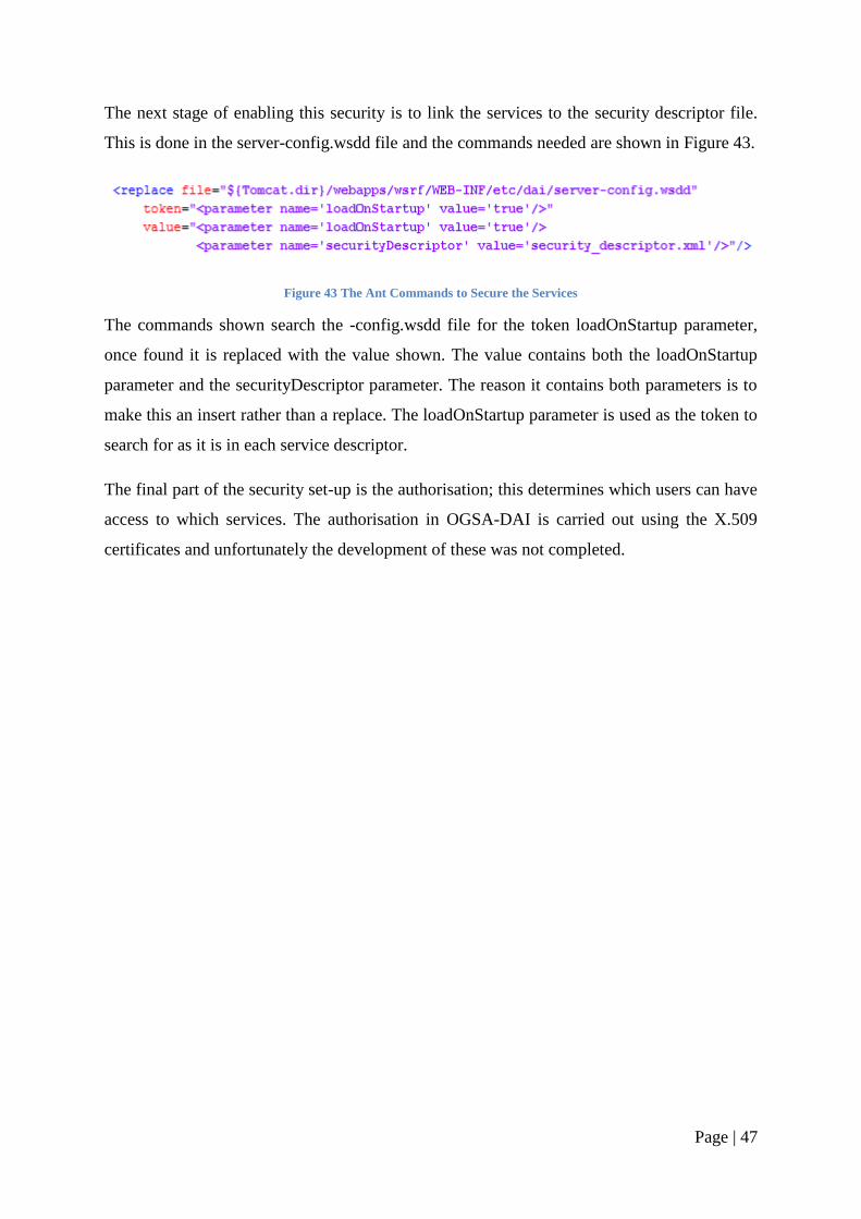
The next stage of enabling this security is to link the services to the security descriptor file.
This is done in the server-config.wsdd file and the commands needed are shown in Figure 43.
Figure 43 The Ant Commands to Secure the Services
The commands shown search the -config.wsdd file for the token loadOnStartup parameter,
once found it is replaced with the value shown. The value contains both the loadOnStartup
parameter and the securityDescriptor parameter. The reason it contains both parameters is to
make this an insert rather than a replace. The loadOnStartup parameter is used as the token to
search for as it is in each service descriptor.
The final part of the security set-up is the authorisation; this determines which users can have
access to which services. The authorisation in OGSA-DAI is carried out using the X.509
certificates and unfortunately the development of these was not completed.
Page | 48
4. Evaluation
4.1. Evaluation of Implementation
4.1.1. Evaluation of Finished Installer
The main goal for this project was to produce a complete installer that could set-up a machine
capable of storing clinical trial data; the machine also needed to be remotely accessible. This
goal has been achieved; the installer sets up a local database with a schema designed to
manage the trial data. The resource is exposed with a Tomcat web server and a GT web
service core, into which OGSA-DAI is deployed.
In order to achieve this main goal of a complete installer four goals were set out
A refined installer, minimising user input while maintaining enough freedom to satisfy
network and system administrators
The means of adding a database and exposing its resources
The ability to enable the security infrastructure
A platform independent installer
The first goal was achieved and the installation processes have been simplified. When
deploying the server with a local database the user is confronted with only two input screens
asking for simple host and user details. Also thanks to the IzPack software, and its sole
dependency on the Java Virtual Machine, it means there is no complicated set-up before the
installer can be run. This step, although one of the simplest to implement, was also one of the
hardest to achieve. The balance between minimising user interaction, while still giving the
flexibility in the set-up, was a fine line to tread. Information, such as the connection URI,
could be hard coded to prevent errors but the resource name needed to be editable so users
could change its value to match their clients. This process of refinement was ongoing
throughout the project as each new feature created new issues in the balance of the installer.
One way to avoid this constant iteration after each change would have been to implement this
step last, once all the features had been added. An example of this is the addition of the local
database. This was the second goal but its addition meant that three screens could be
condensed into one, thus achieving progress with the refinement.
The second goal required the addition of a local database, which was realized by attaching a
MySQL database server installation. Now, when a user chooses to, a MySQL database is
Page | 49
installed and the schema specified by Rob Kitchen is applied to it. Once this is complete the
database is exposed as an OGSA-DAI resource. One aspect in the database installation was
the need for the flexibility to change the schema definition. By using an SQL file as part of
the set-up scripts rather than hard coding the SQL statements, the schema can be updated or
replaced without the need to modify the installer.
The third goal was the addition of security into the setup. Whilst securing the server was a
relatively easy task, the problem came with the authorisation and authentication. To secure
the server required changes to the OGSA-DAI configuration files and the server set-up as
discussed in Section 3.5. The second stage of the security set-up is the addition of the
authorisation, defining which user can have access to the server. As discussed previously the
Globus Toolkit security model relies on the X.509 standard. This reliance on certificates
caused problems in the development as a certificate infrastructure needed to be created,
including a certificate authority, user certificates and host certificates. This implementation
was unable to be completed mainly due to the complexity of the development and the short
space of time allocated for it to be achieved.
The fourth goal of keeping the installer platform independent was achieved utilising the
IzPack framework. By utilizing the ability of IzPack to distinguish the host operating system,
different scripts and commands could be executed, on both Windows and UNIX systems, to
achieve the same goals.
4.1.2. Robustness
4.1.2.1. Inputs
One problem that could arise with inputs is if the fields are left blank. An area where this
would be a problem is in the user name and password fields. This problem has been avoided
by utilising a validator class from the IzPack software. The class NotEmptyValidator checks
that an input is placed into the field and will not let the installer proceed until it has been
done. All the other fields combat this problem by having default inputs. If a user does delete
the default and fails to replace it, the installer will fail. This problem could be solved simply
by enabling the validator on all fields.
Another area where user input can cause errors in the program is the host port. If a non
integer is placed in this field it will cause problems with the web server set-up. The installer
Page | 50
itself will complete without error and the web server will run. However, when trying to
access the applications and services on the web server, the requests will fail.
4.1.2.2. A space in install path
One problem identified with the installer is in the choice of target directory. If a space is
included in the target directory such as ―Program files‖ the installer fails when trying to
deploy the resources. The error presented to the user is ogsadai-3.0-gt-4.0.5-bin\build.xml
line 637: Java returned 1.
4.1.2.3. Multiple installs
The installer is not set-up for multiple installs and problems will arise when they are
attempted. The main problem with a multiple install is automatic start up configuration. The
host operating system can only have one program of a given name as an automatic start up
program. As this installer has the names of the web server and database hard coded this
causes a problem with multiple installs. Without this automated start up problem the only
issue with running the installer multiple times on the same machine is the port number. So
long as each set-up has a different port number then they can run side by side without
problems.
4.1.3. Problems with the Development
As discussed in the implementation chapter the development environment used was a virtual
machine (VM) using virtual pc 2007. This gave a lot of advantages to the development, the
key one being that a clean operating system could be loaded each time the installer was
tested. The use of a VM did however create some problems leading to delays in development.
The major issue with the VM was the speed, the installer took around 15 minutes to complete
on the VM which meant debugging took a lot of time.
Another problem was discovered with the network mapping on the VM. When the OGSA-
DAI was deployed on the VM, although the web server could be accessed and a list of the
OGSA-DAI services displayed, the services themselves could not be accessed. The exact
fault could not be determined so instead the testing was moved on to a real operating system
and the problem was resolved. The main reason for this problem not being resolved more
quickly was due to difficulty in diagnosing what the problem was. When the problem first
started it was still possible to access some of the services but not others therefore it was
assumed (wrongly) that the problem was in the setup not in the operating system. It was not
Page | 51
until the original services also stopped working that the installer was tried on a real machine
and a solution was produced.
Another major problem with the development was in the schema deployment. It was
originally thought the schema could be deployed using a Java client. As discussed in Section
3.4.2 to use a Java client to deploy the schema would require a user account on the database
with total privileges that can be accessed from an unknown host. It was originally thought
that just a local host account would be suitable but when this was implemented the OGSA-
DAI resource failed. Once it was discovered that a separate multi host user would be needed,
development was switched to scripts rather than Java clients. The main reason for the switch
to scripts was that a script was needed to execute the SQL commands which were necessary
to set-up the multi host user. Once it had been decided that this script was required it was felt
unnecessary to then use a Java client to execute the other SQL statements. The change to
scripts did have an advantage in that it meant the database could be better secured without the
multi host user. However the change did slow development as the Java client had already
been written before the problem was discovered.
4.2. Evaluation of the Original Work Plan
4.2.1. Evaluation of Chosen Software Engineering Methodology
The agile methodology as outlined in Section 2.5.1 worked well for this project. The
structured breakdown of work led to an efficient development period. This structured
breakdown was also a major benefit to the implementation as each stage of the program could
be developed separately and then tested before moving on to the next phase.
One of the drawbacks to agile methodologies is the risk of repetition in development. Each
phase is designed and implemented in the simplest manner without thought to later additional
functionality. One area which was affected in this development was in the second phase:
where the aim was to add a local database installer. The addition of the database installation
had the side effect of also simplifying the interface; this had been the aim of the first phase
but was much more effective with the addition of a local database.
4.2.2. Evaluation of the Schedule
The schedule of work changed in a number of ways, which can be seen in Figure 44. The
most significant of these changes was the order of prototype releases. The second and third
prototype releases were switched; the reason for this exchange was that it was felt that the
Page | 52
third prototype was critical to fulfilling the primary goal of simplifying the installer. By
adding a local database the user interface was cut by three screens and the complexity of user
input was greatly reduced. Other changes to the schedule were mainly due to delays in
development. As mentioned above a problem with the virtual machine caused the tests of
database deployment to fail. These negative test results caused a delay which is shown in the
extended development time of prototype three. This delay in prototype three had follow-on
consequences, which led to the implementation phase continuing after the proposed cut off
point. This implementation extension meant that instead of dedicated write up time in weeks
11 and 12 the final aspects of the report had to be finished concurrently with the final
implementation.
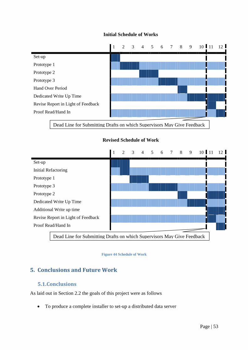
Page | 53
Figure 44 Schedule of Work
5. Conclusions and Future Work
5.1. Conclusions
As laid out in Section 2.2 the goals of this project were as follows
To produce a complete installer to set-up a distributed data server
Initial Schedule of Works
1 2 3 4 5 6 7 8 9 10 11 12
Set-up
Prototype 1
Prototype 2
Prototype 3
Hand Over Period
Dedicated Write Up Time
Revise Report in Light of Feedback
Proof Read/Hand In
Revised Schedule of Work
1 2 3 4 5 6 7 8 9 10 11 12
Set-up
Initial Refactoring
Prototype 1
Prototype 3
Prototype 2
Dedicated Write Up Time
Additional Write up time
Revise Report in Light of Feedback
Proof Read/Hand In
Dead Line for Submitting Drafts on which Supervisors May Give Feedback
Dead Line for Submitting Drafts on which Supervisors May Give Feedback
Page | 54
To create a simple user interface to facilitate the rapid deployment of data servers by
non experienced users
To satisfy the requirements set by system administrators in terms of flexibility and
security
The installer developed fulfils two of these goals and sets up a server with a Tomcat web
server and a GT web service core, into which OGSA-DAI is deployed. The installer also
installs a MySQL database server and exposes a schema defined database using OGSA-DAI.
There is a simple user interface to facilitate the rapid deployment by non experienced users.
When deploying the server with a local database the user is confronted with only two input
screens asking for simple host and user details. Rapid deployment is achieved thanks to the
IzPack software and its sole dependency on the Java virtual machine, meaning no
complicated set-up before the installer can be run. Unfortunately the security component of
the system has not been fully developed. As mentioned previously the X.509 certificate based
security model provided many challenges. The process of securing the server has been
completed but without proper authorisation it means that the task is not yet finalised.
The installer is fairly robust and can handle a number of common problems such as errors in
user input. The problem of null fields is addressed with default values and a validator class
checking for input. One area where the installer is not so robust is in multiple installs. The
main problem is that the installer integrates the programs with the operating system and this
can only be done once. However if the operating system integration is removed then the
installer can be run multiple times on the same machine.
The success of this project is one further step towards the aim of providing distributed data
sources able to contain the data from not only the Molecular Medicine Centre‘s cystic fibrosis
clinical trials but also other clinical trials from other institutions across the globe.
5.2. Future Development
The first major piece of follow on work to this project should be the adaptation of the current
client system to utilise the OGSA-DAI resources deployed using this installer. Once this
modification is completed then the system envisioned in Figure 4 can be made a reality.
Further work to the installer will come in the form of firstly correcting the flaws identified in
the robustness tests. Another area where the installer could be improved is in the automatic
detection of current software. For example if a Tomcat server is already on the system this
Page | 55
installer will have problems. One thing that could be done to improve this would be for the
installer to detect this server and deploy OGSA-DAI and the Globus Toolkit onto it. More
work will also be needed to finish the development of the security model. A certificate
hierarchy will need to be developed and then this can be combined with the installer.
Lastly an extension to the project could come in the form of a different security framework.
The current installer utilises the security model supported by OGSA-DAI. The X.509
certificate based security model may be too complex for the biologist to use in conjunction
with the client system. A custom authentication and authorisation model could be constructed
to simplify the users‘ involvement in the security process.

Page | 56
6. Bibliography
1. Cystic Fibrosis Trust. What causes Cystic Fibrosis?:Cystic Fibrosis Trust. Cystic Fibrosis
Trust Web site. [Online] [Cited: 24 july 2008.]
http://www.cftrust.org.uk/aboutcf/whatiscf/whatcausescf/.
2. Medical Genetics Section. Overview: Medical Genetics Section. Medical Genetics
Section. [Online] [Cited: 24 july 2008.] http://www.genetics.med.ed.ac.uk/cysfib/.
3. Agilent Technologies. 2100 Bioanalyzer: Agilent Technologies. Agilent Technologies.
[Online] [Cited: 24 july 2008.] http://www.chem.agilent.com/scripts/pds.asp?lpage=51.
4. Kitchen, Rob. Wrapping Tools to Automate Workflows for Gene Expression Analyses in
Cystic Fibrosis. Edinburgh : s.n., 2007.
5. OGSA-DAI. OGSA-DAI. [Online] [Cited: 24 july 2008.]
http://www.ogsadai.org.uk/about/ogsa-dai/.
6. —. Documentation Overview: OGSA-DAI. OGSA-DAI. [Online] OGSA-DAI. [Cited: 24
july 2008.] http://www.ogsadai.org.uk/documentation/ogsadai3.0/ogsadai3.0-
gt/Overview.html#OverviewWhatIsOGSADAI.
7. Sun Micro Systems. Home: Java. Java. [Online] [Cited: 25 july 2008.]
http://www.java.com/en/.
8. Apache. Home: Apache. Apache Ant. [Online] [Cited: 25 july 2008.]
http://ant.apache.org/.
9. GNU. GNU Compiler Collection. GNU Compiler Collection. [Online] 5 july 2008. [Cited:
27 july 2008.] http://gcc.gnu.org/.
10. BEinGRID. Welcome: BEinGRID. BEinGRID. [Online] [Cited: 24 july 2008.]
www.beingrid.com/.
11. wikipedia. Extreme_Programming: wikipedia. wikipedia. [Online] [Cited: 24 july 2008.]
http://en.wikipedia.org/wiki/Extreme_Programming.
12. Microsoft. Virtual PC 2007: Microsoft. Microsoft. [Online] [Cited: 9 august 2008.]
http://www.microsoft.com/windows/products/winfamily/virtualpc/default.mspx.
Page | 57
13. Eclipse. Home: Eclipse. Eclipse. [Online] [Cited: 10 august 2008.]
http://www.eclipse.org/org/.
14. MySQL. MySQL. MySQL. [Online] [Cited: 24 july 2008.] www.mysql.com.
15. Chris, Bennett and Daniel, Peckham. The Genetics of Cystic Fibrosis: Cystic Fibrosis
Medicine. Cystic Fibrosis Medicine. [Online] August 2002. [Cited: 24 july 2008.]
http://www.cysticfibrosismedicine.com/htmldocs/CFText/genetics.htm.
16. Ian, Foster, Carl, Kesselman and Steven, Tuecke. The Anatomy of the Grid Enabling
Scalable Virtual Organizations. Globus. [Online] [Cited: 24 july 2008.]
http://www.globus.org/alliance/publications/papers/anatomy.pdf.
17. The Storage Resource Broker Project: University of Queensland Australia. University of
Queensland australia. [Online] [Cited: 24 july 2008.]
http://www.vislab.uq.edu.au/research/SRB/background.html.
18. The Centre for Molecular Medicine. The Centre for Molecular Medicine. The Centre
for Molecular Medicine. [Online] [Cited: 24 july 2008.] http://www.mmc.med.ed.ac.uk/.
19. Globus. Main page: Globus. Globus. [Online] [Cited: 24 july 2008.]
http://www.globus.org/.
20. Apache. Apache. Apache. [Online] [Cited: 24 july 2008.] http://apache.org/.
21. IzPack. home: IzPack. IzPack. [Online] [Cited: 24 july 2008.] http://izpack.org/.
22. San Diego Supercomputer Center. home: San Diego Supercomputer Center. San Diego
Supercomputer Center. [Online] [Cited: 24 july 2008.] http://www.sdsc.edu/.
23. iIRODS. home: iIRODS. iIRODS. [Online] [Cited: 24 july 2008.] https://www.irods.org/.
24. Susan, Malaika and Dirk, Hain. Accessing DB2 Universal Database using the Globus
Toolkit and OGSA-DA: IBM Developerworks. IBM Developerworks. [Online] 14 August
2003. [Cited: 27 july 2008.]
http://www.ibm.com/developerworks/db2/library/techarticle/0308malaika/0308malaika.html.
25. OGSA-DAI 3.0 – The Whats and the Whys. Antonioletti, Mario, et al. Edinburgh : All
Hands Meeting, 2007.
Page | 58
26. The Design and Implementation of Grid Database Services in OGSA-DAI. Antonioletti,
M., et al. 2-4, 2005, Concurrency and Computation: Practice and Experience, Vol. 17, pp.
Pages 357-376.
27. Introduction to OGSA-DAI Services. Karasavvas, K., et al. may 2005, Lecture Notes in
Computer Science, Vol. 3458, pp. 1-12.
28. Globus. Chapter 10.2: The Globus Toolkit 4 Programmer's Tutorial. The Globus Toolkit
4 Programmer's Tutorial. [Online] [Cited: 4 august 2008.] http://gdp.globus.org/gt4-
tutorial/multiplehtml/ch10s02.html.
7. Appendix
Recommended