UNIVERSITI TEKNIKAL MALAYSIA MELAKA
IMPROVEMENT OF THE EFFICIENCY OF MINI
THERMOELECTRIC REFRIGERATOR BY USING PELTIER
MODULE
This report is submitted in accordance with the requirement of the Universiti
Teknikal Malaysia Melaka (UTeM) for the Bachelor of Mechanical Engineering
Technology (Refrigeration and Air-Conditioning Systems) with Honours
by
LEE WEI HAU
B071210144
920628-02-5425
FACULTY OF ENGINEERING TECHNOLOGY 2015
UNIVERSITI TEKNIKAL MALAYSIA MELAKA
BORANG PENGESAHAN STATUS LAPORAN PROJEK SARJANA MUDA
TAJUK: Improvement of the Efficiency of Mini Thermoelectric Refrigerator by
Using Peltier Module
SESI PENGAJIAN: 2015/16 Semester 1
Saya LEE WEI HAU
mengaku membenarkan Laporan PSM ini disimpan di Perpustakaan Universiti
Teknikal Malaysia Melaka (UTeM) dengan syarat-syarat kegunaan seperti berikut:
1. Laporan PSM adalah hak milik Universiti Teknikal Malaysia Melaka dan penulis. 2. Perpustakaan Universiti Teknikal Malaysia Melaka dibenarkan membuat salinan
untuk tujuan pengajian sahaja dengan izin penulis. 3. Perpustakaan dibenarkan membuat salinan laporan PSM ini sebagai bahan
pertukaran antara institusi pengajian tinggi.
4. **Sila tandakan ( )
SULIT
TERHAD
TIDAK TERHAD
(Mengandungi maklumat yang berdarjah keselamatan
atau kepentingan Malaysia sebagaimana yang termaktub
dalam AKTA RAHSIA RASMI 1972)
(Mengandungi maklumat TERHAD yang telah ditentukan
oleh organisasi/badan di mana penyelidikan dijalankan)
____________________
Alamat Tetap:
198, Taman Pulasan
Jalan Alor Mengkudu
05400 Alor Star, Kedah
Tarikh: ________________________
Disahkan oleh:
____________________
Cop Rasmi:
Tarikh: _______________________
** Jika Laporan PSM ini SULIT atau TERHAD, sila lampirkan surat daripada pihak berkuasa/organisasi
berkenaan dengan menyatakan sekali sebab dan tempoh laporan PSM ini perlu dikelaskan sebagai
SULIT atau TERHAD.
iii
DECLARATION
I hereby, declared this report entitled “Improvement of the Efficiency of Mini
Thermoelectric Refrigerator by Using Peltier Module” is the results of my own
research except as cited in references.
Signature : ………………………
Name : ………………………
Date : ………………………

iv
APPROVAL
This report is submitted to the Faculty of Engineering Technology of UTeM as a
partial fulfillment of the requirements for the degree of Bachelor of Mechanical
Engineering Technology (Refrigeration and Air-Conditioning Systems) (Hons.).
The member of the supervisory is as follow:
……………………………….
(Project Supervisor)

v
ABSTRACT
The human activity of releasing chlorofluorocarbons (CFCs) and hydrofluorocarbons (HCFCs) from vapour compression refrigeration systems have caused adverse impact to the environment. This phenomenon leads to the necessity of developing air-conditioning and refrigeration technologies which are more environmentally friendly and energy-efficient. Thermoelectric refrigerator is one of the most promising devices that suit this requirement. This device consists of Peltier module as one of its vital components. Since it is not driven by compressor, thermoelectric refrigerator offers several advantages such as light weight, easy maintenance and less noisy as compared to conventional compressor-driven vapour compression refrigerator. When electric current applied to a Peltier module, the hot side of the module becomes very hot, thus it needs a heat sink to dissipate the heat to the surrounding. In this study, several prototypes of mini thermoelectric refrigerators were fabricated by using Peltier module as its main components. This study aims to improve the dissipation of the heat at the hot side of Peltier module in order to achieve lower cooling temperature of the mini refrigerator. The effects of several parameters on the temperature of the hot side of the Peltier module were investigated. These parameters are ambient temperature, insulation materials, design of heat sink, the direction of air flow by fan, quantity of electric current and the effect of using paraffin Phase Change Material (PCM) as a cooling source. The result showed that the main parameters affected the temperature of the Peltier module was the quantity of electric current. This is because the more electric current supplied, the greater the temperature difference between the hot and cold sides of the Peltier module. The design of heat sink is also very important in order to dissipate the heat efficiently. The lowest cooling temperature of the mini refrigerator was 11℃ and the thermal efficiency was 5.79%. With further improvement especially in the techniques of reducing the temperature of the hot side of the Peltier module, thermoelectric refrigerator can be developed further to achieve lower cooling temperature and more energy-efficient. Thus, thermoelectric refrigerator would provide an alternative technology to replace the conventional compressor-driven vapour compression refrigerator for some applications.

vi
ABSTRAK
Aktiviti manusia yang melepaskan klorofluorokarbon dan hydrofluorocarbons daripada sistem penyejukan telah memberi kesan negatif kepada alam sekitar. Fenomena ini melahirkan konvensional keperluan untuk membangunkan teknologi penghawa dingin dan penyejukan yang lebih mesra alam dan cekap tenaga. Peti sejuk termoelektrik adalah salah satu peranti yang paling sesuai untuk memenuhi keperluan ini. Peranti ini terdiri daripada modul Peltier sebagai salah satu komponen yang utama. Disebabkan ia tidak mengguna pemampat, peti sejuk termoelektrik mempunyai beberapa kelebihan seperti ringan, mudah diselenggara dan kurang bising berbanding dengan sistem penyejukan yang menggunakan pemampat konvensional. Apabila arus elektrik mengalir ke modul Peltier, bahagian panas modul akan menjadi sangat panas, oleh itu pelepas haba diperlukan untuk melepaskan haba ke persekitaran. Dalam kajian ini, beberapa mini prototaip peti sejuk termoelektrik telah direka dengan menggunakan modul Peltier sebagai komponen yang utama. Kajian ini bertujuan untuk meningkatkan pelepasan haba di bahagian panas modul Peltier untuk mencapai suhu penyejukan yang lebih rendah. Beberapa parameter yang memberi kesan kepada bahagian suhu panas modul Peltier itu telah dikaji. Parameter tersebut ialah suhu persekitaran, bahan-bahan penebat peti sejuk, reka bentuk pelepas haba, arah aliran udara oleh kipas, kuantiti arus elektrik dan kesan bahan perubahan fasa parafin sebagai sumber penyejukan juga telah dikaji. Hasilnya menunjukkan bahawa parameter utama yang mempengaruhi suhu modul Peltier itu ialah kuantiti arus elektrik. Ini disebabkan semakin tinggi arus elektrik dibekalkan, semakin besar perbezaan suhu di antara bahagian panas dan sejuk modul Peltier. Reka bentuk pelepas haba juga ialah parameter yang penting dalam kajian ini. Ia menjadi salah satu komponen yang utama untuk menyebarkan haba dengan cekap. Suhu penyejukan terendah yang dicapai oleh mini peti sejuk ialah 11℃ dan kecekapan tenaga ialah 5.79%. Dengan penambahbaikan terutamanya dalam teknik-teknik mengurangkan suhu bahagian panas modul Peltier, peti sejuk termoelektrik boleh ditambah baik lagi untuk mencapai suhu penyejukan yang lebih rendah dan kecekapan tenaga yang lebih tinggi. Oleh itu, peti sejuk termoelektrik boleh menawarkan suatu teknologi alternatif untuk menggantikan sistem penyejukan konvensional yang menggunakan pemampat bagi aplikasi tertentu.

vii
DEDICATIONS
This thesis is dedicated to my beloved parents, supervisor and friends for their help
and guidance to complete the final year project successfully.

viii
ACKNOWLEDGMENTS
First and foremost, I would offer my sincere gratitude to my supervisor Encik
Aludin Bin Mohd Serah for his knowledge, understanding and most importantly
patience while guiding me. Without his guidance, encouragement and patience, this
project would never have been completed on time. For everything you have done for
me, Encik Aludin I thank you. I could not have wished for a better adviser, as a
teacher and a person.
I would also like to thank all my friends for their encouragement and support
when I faced any problems and difficulty in completing this project. I am very
grateful with the co-operation from the lecturer and technicians who borrow the
instruments and the laboratory in order to complete the test in the result of my
project. Last and but not least, I would like to express the highest gratitude to my
parents and my family for giving me the moral support when I need them. Words just
cannot illustrate how much I thank all of you.
ix
TABLE OF CONTENTS
DECLARATION ................................................................................................................. iii
APPROVAL ......................................................................................................................... iv
ABSTRACT ........................................................................................................................... v
ABSTRAK ........................................................................................................................... vi
DEDICATIONS .................................................................................................................. vii
ACKNOWLEDGMENTS.................................................................................................. viii
TABLE OF CONTENTS ..................................................................................................... ix
LIST OF FIGURES............................................................................................................ xiii
LIST OF TABLE ................................................................................................................. xv
LIST OF SYMBOLS AND ABBREVIATIONS .............................................................. xvi
CHAPTER 1........................................................................................................................... 1
1.0 Introduction ............................................................................................................. 1
1.1 Project Background ................................................................................................. 1
1.2 Problem Statement................................................................................................... 5
1.3 General Objective of Research ................................................................................ 5
1.3.1 Specific Objectives........................................................................................... 5
1.4 Scope of Research ................................................................................................... 6
CHAPTER 2........................................................................................................................... 7
2.0 Introduction ............................................................................................................. 7
x
2.1 A Brief History of Thermoelectric .......................................................................... 7
2.2 Thermoelectric Coolers ......................................................................................... 10
2.2.1 Peltier Module ................................................................................................ 10
2.2.2 Application of Peltier Module ........................................................................ 12
2.2.3 Advantages of Peltier Module ........................................................................ 12
2.2.4 Disadvantages of Peltier Module ................................................................... 13
2.3 Thermoelectric Refrigerator .................................................................................. 13
2.3.1 Internal Components of A Peltier Module ..................................................... 14
2.3.2 Thermoelectric Materials ............................................................................... 15
2.3.3 How Thermoelectric Coolers Work ............................................................... 16
2.3.4 Heat Sink ........................................................................................................ 17
2.3.4.1 Types of Heat Sinks ................................................................................ 18
2.4 Phase Change Material (PCM) .............................................................................. 20
2.4.1 Classification of PCM .................................................................................... 22
2.4.2 Organic PCM ................................................................................................. 23
CHAPTER 3......................................................................................................................... 24
3.0 Introduction ........................................................................................................... 24
3.1 Overall View of a Mini Thermoelectric Refrigerator............................................ 24
3.2 Prototypes of Mini Thermoelectric Refrigerator ................................................... 26
3.2.1 Prototype 1 ..................................................................................................... 26
3.2.2 Prototype II..................................................................................................... 27
3.2.3 Prototype III ................................................................................................... 28
3.3 Selection of Materials and Specifications ............................................................. 29
xi
3.3.1 Types of Peltier Module ................................................................................. 29
3.3.1.1 General Specifications of Peltier Module ............................................... 30
3.3.2 Cooling Element............................................................................................. 34
3.3.3 Heat Sink ........................................................................................................ 35
3.3.4 Fan Assembly with Heat Sink ........................................................................ 36
3.3.5 Electrical Connection of Peltier Module ........................................................ 37
3.3.6 Phase Change Material (PCM)....................................................................... 38
3.3.7 List of Materials ............................................................................................. 38
3.4 Calculation of Coefficient of Performance (COP) ................................................ 39
3.4.1 Method 1 ........................................................................................................ 40
3.4.2 Method 2 ........................................................................................................ 40
CHAPTER 4......................................................................................................................... 42
4.0 Introduction ........................................................................................................... 42
4.1 Prototype and Parameters ...................................................................................... 42
4.2 Effect of Each Parameter ....................................................................................... 43
4.2.1 Effect of Ambient Temperature and Insulation Material ............................... 43
4.2.2 Effect of Heat Sink Design ............................................................................ 45
4.2.3 Effect of Phase Change Material (PCM) ....................................................... 50
4.2.4 Effect of Fan Air Flow Direction ................................................................... 54
4.2.5 Effect of Quantity of Electric Current ............................................................ 57
4.3 Graph Analysis for Each Parameter Studied ......................................................... 61
4.3.1 Effect of Ambient Temperature and Insulation Material ............................... 61
4.3.2 Effect of Heat Sink Design ............................................................................ 62
xii
4.3.3 Effect of Phase Change Material (PCM) ....................................................... 65
4.3.4 Effect of Fan Air Flow Direction ................................................................... 67
4.3.5 Effect of Quantity of Electric Current ............................................................ 69
4.4 Calculation of Efficiency ....................................................................................... 71
4.4.1 Method 1 ........................................................................................................ 72
4.4.2 Method 2 ........................................................................................................ 73
CHAPTER 5......................................................................................................................... 75
5.0 Introduction ........................................................................................................... 75
5.1 Summary of Research............................................................................................ 75
5.2 Achievement of Research Objectives .................................................................... 78
5.3 Significance of Research ....................................................................................... 79
5.4 Problems Faced During Research ......................................................................... 79
5.5 Suggestion for Future Work .................................................................................. 80
REFERENCES ..................................................................................................................... 82

xiii
LIST OF FIGURES
Figure 1.1: Green House Effect ................................................................................... 2
Figure 1.2: Vapor Compression Refrigeration System ................................................ 2
Figure 1.3: Seebeck Effect ........................................................................................... 3
Figure 1.4: Peltier Effect .............................................................................................. 4
Figure 1.5: Peltier Module ........................................................................................... 4
Figure 2.1: Thomas Johann Seebeck ............................................................................ 7
Figure 2.2: Instrument Used by Seebeck ..................................................................... 8
Figure 2.3: First Idea of Thermoelectric Device .......................................................... 9
Figure 2.4: Seebeck Effect ......................................................................................... 11
Figure 2.5: Peltier Effect ............................................................................................ 11
Figure 2.6: Internal Components of A Peltier Module .............................................. 14
Figure 2.7: Electrical and Thermal Connectivity of Thermoelectric Couples Within a Module ....................................................................................................................... 15
Figure 2.8: Thermoelectric Figure of Merit of Semiconductor Materials ................. 16
Figure 2.9: N-type Semiconductor Element Utilized to Facilitate the Peltier Effect . 17
Figure 2.10: Stampings Heat Sink ............................................................................. 18
Figure 2.11: Extrusions Heat Sinks ............................................................................ 19
Figure 2.12: Bonded / Fabricated Fins ....................................................................... 19
Figure 2.13: Castings Heat Sink................................................................................. 20
Figure 2.14: Folded Heat Sinks .................................................................................. 20
Figure 2.15: Phase Transformation of PCM .............................................................. 21
Figure 2.16: Paraffinic PCM ...................................................................................... 21
Figure 2.17: Classification of PCMs .......................................................................... 22
Figure 3.1: A Mini Thermoelectric Refrigerator........................................................ 25
Figure 3.2: Exploded View of Prototype I ................................................................. 27
Figure 3.3: Exploded View of Prototype II ................................................................ 28
Figure 3.4: Exploded View of Prototype III .............................................................. 29
Figure 3.5: Peltier Module Type A ............................................................................ 30
Figure 3.6: Peltier Module Type B ............................................................................ 30
Figure 3.7: A Sample of Peltier Module, ID: TEC1-12709 ....................................... 31
Figure 3.8: Performance Curve of the Peltier Module ............................................... 32
Figure 3.9: Finned Surface Heat Sink ........................................................................ 35
Figure 3.10: Aluminum Heat Sink with the Fan Assembly ....................................... 36
Figure 3.11: Connection of Peltier Module................................................................ 37
Figure 4.1: Prototype I ............................................................................................... 44
Figure 4.2: Double-sided Finned Heat Sink ............................................................... 46

xiv
Figure 4.3: Single-sided Finned Heat Sink ................................................................ 46
Figure 4.4: Prototype II .............................................................................................. 47
Figure 4.5: Prototype III ............................................................................................. 47
Figure 4.6: Heat Sink Without PCM .......................................................................... 50
Figure 4.7: Heat Sink With PCM ............................................................................... 51
Figure 4.8: Upward Direction .................................................................................... 54
Figure 4.9: Inward Direction ...................................................................................... 55
Figure 4.10: Power Source of 3 Ampere .................................................................... 57
Figure 4.11: AC-DC Adapters of 5 Ampere .............................................................. 58
Figure 4.12: Effect of Ambient Temperature and Insulation Material ...................... 61
Figure 4.13: Effect of Heat Sink Design of Prototype II ........................................... 62
Figure 4.14: Effect of Heat Sink Design of Prototype III .......................................... 63
Figure 4.15: Effect of Heat Sink Design for Prototype II and III .............................. 63
Figure 4.16: Bottom Surface of the Heat Sink ........................................................... 64
Figure 4.17: Effect Without PCM .............................................................................. 65
Figure 4.18: Effect With PCM ................................................................................... 65
Figure 4.19: Effect With and Without PCM .............................................................. 66
Figure 4.20: Effect of Air Flow Outward................................................................... 67
Figure 4.21: Effect of Air Flow Inward ..................................................................... 67
Figure 4.22: Effect of Air Flow Outward and Inward ............................................... 68
Figure 4.23: Fan Remove Heat to the Surrounding ................................................... 68
Figure 4.24: Effect of 3 Ampere by Power Source .................................................... 69
Figure 4.25: Effect of 5 Ampere by AC-DC Adapter ................................................ 69
Figure 4.26: Effect of 3 and 5 Ampere ...................................................................... 70
Figure 5.1: The Effect of Ambient Temperature, Electric Current and PCM on the Peltier Module. ........................................................................................................... 77
Figure 5.2: PCM With the Heat Sink and the Fan ..................................................... 80
Figure 5.3: Recommended of the Arrangement of the Components ......................... 81

xv
LIST OF TABLE
Table 2.1: Summary of Thermoelectric Effect ............................................................ 9
Table 3.1: Summarizes the Prototypes and the Parameters to be Studied For Each Prototype .................................................................................................................... 25
Table 3.2: The general Specifications of the Peltier Module ..................................... 33
Table 3.3: Comparison of Different Cooling Materials ............................................. 34
Table 3.4: Range of Heat Transfer Efficiencies for Common Types of Heat Sinks .. 35
Table 3.5: List of Materials ........................................................................................ 39
Table 4.1: Study the Relationship of the Effect and the Prototype ............................ 43
Table 4.2: Data for the Temperature of the Plastic Container ................................... 44
Table 4.3: Temperature Data When Double-sided Finned Heat Sink Used In Prototype II................................................................................................................. 48
Table 4.4: Temperature Data When Single-sided Finned Heat Sink Used In Prototype III ................................................................................................................................ 49
Table 4.5: Data of Heat Sink Without PCM .............................................................. 52
Table 4.6: Data of Heat Sink With PCM ................................................................... 53
Table 4.7: Data Upward Direction ............................................................................. 55
Table 4.8: Data Inward Direction............................................................................... 56
Table 4.9: Data for Power Source of 3 Ampere ......................................................... 59
Table 4.10: Data for AC-DC Adapter of 5 Ampere ................................................... 60
Table 4.11: Efficiency of the Prototype III for 5 Ampere.......................................... 72
Table 5.1: The Efficiency of the Parameters .............................................................. 76

xvi
LIST OF SYMBOLS AND ABBREVIATIONS
A = Ampere
AC = Alternating Current
AIN = Aluminium Nitride
Bi2Te3 = Bismuth Telluride
Bi-Sb = Bismuth-Antimony
CFCs = chlorofluorocarbons
COP = coefficient of performance
DC = Direct Current
EMF = electromotive force
HCFCs = hydrochlorofluorocarbons
n = Neutron
p = Proton
PbTe = Lead Telluride
PCM = Phase Change Material
SiGe = Silicon Germanium
Tc = Temperature of cold side
Th = Temperature of hot side
V = Voltage

1
CHAPTER 1 INTRODUCTION
1.0 Introduction
Refrigeration is a process where the work is done to remove the heat from cold
medium to hot medium. The work of the heat transfer is driven by the mechanical
work. A thermoelectric refrigerator functions the same way as a conventional
compressor refrigerator. Thermoelectric device provides a promising alternatives
refrigerator system due to the compressor which is consuming a lot of electricity and
adverse impact to the environment. The thermoelectric refrigerator is using the
Peltier module to function it which also known as thermoelectric module. It works as
a solid state active heat pump which transfers the heat from one side to another side,
with consumption of electrical energy and depending on the direction of the current.
1.1 Project Background
Recently, the activity of releasing chlorofluorocarbons (CFCs) and
hydrochlorofluorocarbons (HCFCs) to the atmosphere from the vapor compression
refrigeration systems has raised the awareness towards environment. It has become a
great concern among researchers, technologist, businessman and politician that leads
to develop of environmentally friendly refrigeration technologies. Hence, many
researches have been conducted to find alternative refrigeration technology in
replacing the old refrigerator system. Nowadays, modern refrigeration system does
not use CFC because CFCs are harmful to the atmosphere and caused the green
house effect which shown in Figure1.1. Instead, the refrigeration system now is using
less harmful HFC which is compressed by compressor in the refrigeration cycle.
2
Figure 1.1: Green House Effect
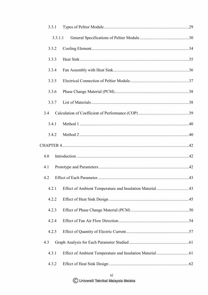
Vapor compression refrigeration system, as shown in Figure 1.2, has
compressor as one of its main component. This system, in which the refrigerant
undergoes phase change, is one of the most widely used systems for air-conditioning
of building and household refrigerators.
Figure 1.2: Vapor Compression Refrigeration System
One of the disadvantages of the compressor is they are very big and heavy. In
this system, liquid refrigerant circulate the system while changing its phase. If any
leakage occurs, the refrigerant might harm the environment. Besides that, it is
expensive to change a new compressor if it is damaged and it is also hard to maintain
3
the system well. The compressor also produces annoying noise and consumes a large
amount of electricity during operation.
Thermoelectric device provides a promising alternatives refrigeration system
as compared to compressor which is consuming a lot of electricity and an adverse
impact to the environment. Thermoelectric cooling has many advantages such as
compact in size, no mechanical moving parts and thus no noise, no working fluid that
make it more environmentally friendly. Seebeck effect is the direct conversion of
temperature differences to electric voltage and vice versa.
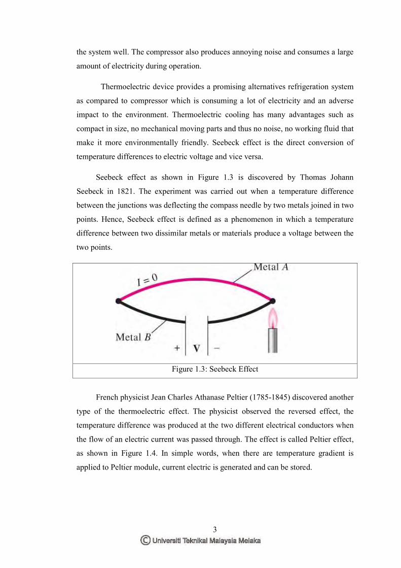
Seebeck effect as shown in Figure 1.3 is discovered by Thomas Johann
Seebeck in 1821. The experiment was carried out when a temperature difference
between the junctions was deflecting the compass needle by two metals joined in two
points. Hence, Seebeck effect is defined as a phenomenon in which a temperature
difference between two dissimilar metals or materials produce a voltage between the
two points.
Figure 1.3: Seebeck Effect
French physicist Jean Charles Athanase Peltier (1785-1845) discovered another
type of the thermoelectric effect. The physicist observed the reversed effect, the
temperature difference was produced at the two different electrical conductors when
the flow of an electric current was passed through. The effect is called Peltier effect,
as shown in Figure 1.4. In simple words, when there are temperature gradient is
applied to Peltier module, current electric is generated and can be stored.

4
Figure 1.4: Peltier Effect
Peltier module is a device that implies Peltier effect which works as a heat
pump which transfers the heat from one side to another side. It consumes electrical
energy and also depending on the direction of the current when it transfers the heat.
This Peltier device functions as heat pump because it does not create heat or cold. It
simply transfers the heat from one side to another side. A Peltier consists of two
plates, that is, one cold side and hot side. Several of the thermocouples are connected
to each other together with two wires as shown in Figure 1.5. When voltage is
applied to both of the wires, the cool side becomes cool whereas the hot side
becomes hot. Peltier is usually made of semiconductor materials.
Figure 1.5: Peltier Module
The hot side becomes very hot after a few minutes of running. Therefore, the
hot side is connected to the heat sink to dissipate the heat to the surrounding.

5
1.2 Problem Statement
In this study, a mini thermoelectric refrigerator was fabricated by using Peltier
module. The Peltier module generates hot side and cold side after applying electrical
current to it. The main problem is the hot side of the Peltier module. This is because
the hot side of the Peltier module generally apply the thermo equilibrium principle
with the cold side of the Peltier module, thus affects the cooling temperature of the
mini refrigerator. The hot side of the Peltier module becomes very hot after a few
minutes of running. Instead, the hot side is connected to the heat sink by dissipating
the heat to the surrounding. However, the cooling temperature of refrigerator using
Peltier module is relatively low. Therefore, in order to increase the cooling
temperature of a mini refrigerator, the effect of the ambient temperature, insulation
material, design of the heat sink, Phase Change Material (PCM), the direction of the
fan air flow and quantity of electric current have to be studied.
1.3 General Objective of Research
To improve the cooling temperature of a mini thermoelectric refrigerator by
several techniques in order to reduce the temperature of the heat sink of the Peltier
module
1.3.1 Specific Objectives
i. To design and fabricate a mini thermoelectric refrigerator by using
Peltier module
ii. To study the effect of ambient temperature, insulation material, design
of the heat sink, Phase Change Material (PCM), the direction of the
fan air flow and quantity of electric current on the cooling temperature
of the mini thermoelectric refrigerator
iii. To calculate the coefficient of performance (COP) of the mini
thermoelectric refrigerator

6
1.4 Scope of Research
In this project, the aim is to design a mini thermoelectric refrigerator which
uses Peltier module and improve its efficiency by several techniques by changing the
insulation material, design of the heat sink, the direction of the air flow, quantity of
electric current and by applying the Phase Change Material (PCM) as a cooling
source. In this research, the efficiency of the mini refrigerator was evaluated mainly
based on the cooling temperature of the mini refrigerator and the coefficient of
performance (COP).

7
CHAPTER 2 LITERATURE REVIEW
2.0 Introduction
This chapter discusses mainly on the history of the thermoelectric and the
application of the Peltier module. The main components of thermoelectric
refrigerator such as Peltier module, design of heat sink and the Phase Change
Material (PCM) have been reviewed in this chapter.
2.1 A Brief History of Thermoelectric
In the year 1822, the study of thermoelectric began when Thomas Johann
Seebeck (1821) as shown in Figure 2.1, a German physicist found that a circuit made
from two different types of metals, with junctions at different temperatures would
deflect a compass magnet, shown in Figure 2.2. This showed that an electric field
was created between the two metals. This was due to magnetism induced by the
temperature differences which deflected the needle.
Figure 2.1: Thomas Johann Seebeck

8
Figure 2.2: Instrument Used by Seebeck
The temperature difference produces an electrical potential which can drive
an electric current in a closed circuit. Today, it is known as the Seebeck effect.
Seebeck then discovered that some metals can create stronger fields with the same
temperature difference and the amount of deflection in the needle was proportional to
the temperature difference between two conducting metals. These principles
provided the foundations of thermoelectric. Later, the Seebeck coefficient was
discovered which means that the voltage was produced between two points of a
conductor where a uniform temperature difference of 1K exists between those two
points. The discovery of the Seebeck coefficient was named after the founding father
of thermoelectric, Thomas Johann Seebeck.
In the year 1834, the thermoelectric materials could also work in reverse and
this was discovered by a French watchmaker named Jean Charles Athanase Peltier
(1834). Peltier found that an electric current would produce heat at the junction of
two different dissimilar metals. Although the discovery of the thermoelectric cooling
is generally credited by Peltier, he did not understand the physics of the
phenomenon. In 1838, Emil Lenz (1838) gave the full explanation by showing him
the heat could either removed from a junction to freeze water into ice, or by
reversing the current, heat can generated to melt ice depending on the direction of the
current. The heat absorbed or created at the junction is proportional to the electric
current which is known as Peltier coefficient.
Recommended