UNIVERSITI PUTRA MALAYSIA
DEVELOPMENT OF ONLINE FACILITIES BOOKING SYSTEM
TAN YI YEIN
FSKTM 2003 14
DEVELOPMENT OF ONLINE FACILITIES BOOKING SYSTEM
TANYIYEIN
FACULTY OF COMPUTER SCIENCE AND INFORMATION TECHNOLOGY
UNIVERSITI PUTRA MALAYSIA
SERDANG, SELANGOR DARUL EHSAN
2003
DEVELOPMENT OF ONLINE FACILITIES BOOKING SYS TEM
By
TAN YIYEIN
A Project Paper submitted in partial fulfillment of the requirement for the degree of
Master of Science (Information Technology) in
Faculty of Computer Science and Information Technology
Universiti Putra Malaysia
2003
I hereby confirmed that I have this project entitled:
DEVELOPMENT OF ONLINE FACILITIES BOOKING SYS TEM
By
TANYIYEIN
I agree that this project is accepted as partial fulfillment of the requirement for the
degree of
Master of Science (Information Technology)
(Pn. Norhayati Mohd Ali)
Faculty of Computer Science and Information Technology
Universiti Putra Malaysia
Date: _1>a:.-__ '")..&D __ 3_
ACKNOWLEDG EMENT
I wish to express my deepest appreciation and profuse thanks to Pn. Norhayati Mohd.
Ali for her advice, support, insightful guidance that made it possible for me to successfully
completes the study.
I would also like to dedicate my gratitude to my friends for their encouragement and
help in the programming; and also my family for their advice, support, concern and
understanding throughout my life.
1
LIST OF FIGURES
Page
Figme 1.1 : System architectme of Facilities Booking System 3
Figme 2.1 : Database access via ODBC 9
Figure 3.1 : Model of prototyping process 11
Figure 3.2 : Entity relationship diagram of Facilities Booking System 15
Figme3.3 : Level 0 DFD of Facilities Booking System 16
Figme 3.4 : Level l process 2.0 of Facilities Booking System 17
Figure 3.5 : Facilities Booking System Architectme Design 20
Figme 3.6 : Facilities Booking System Main Modules 22
Figme4.1 : Main page of Facilities Booking System 27
Figure 4.2 : Register Form for new user 27
Figme4.3 : Confinnation of registration 28
Figme4.4 : Registration successes 28
Figure 4.5 : Usemame taken by existing user 29
Figme4.6 : Login page 30
Figme4.7 : Booking Calendar 31
Figure 4.8 : Booking Details of selected booking 31
Figure 4.9 : Booking Fonn 33
Figme4.10 : Edit booking details 34
Figme4.11 : Booking stunmaty of the current month 34
Figme4.12 : Booking Stunmaty by Facilities 35
11
Table 3.1
Table 3.2
Table 3.3
LIST OF TABLES
: Data structure for Table User
: Data structure for Table Calendar
: Data structure for Table Facilities
111
Page
19
19
20
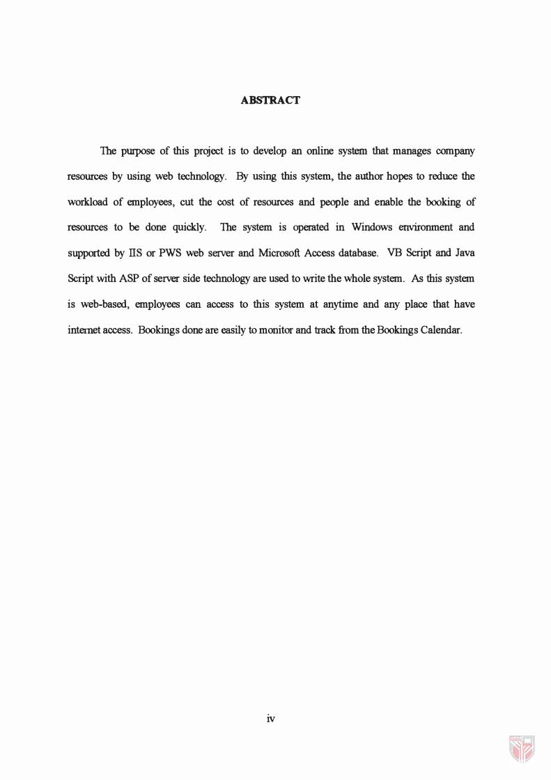
ABSTRACT
The purpose of this project is to develop an online system that manages company
resources by using web technology. By using this system, the author hopes to reduce the
workload of employees, cut the cost of resources and people and enable the booking of
resources to be done quickly. The system is operated in Windows environment and
supported by ns or PWS web server and Microsoft Access database. VB Script and Java
Script with ASP of server side technology are used to write the whole system. As this system
is web-based, employees can access to this system at anytime and any place that have
internet access. Bookings done are easily to monitor and track from the Bookings Calendar.
iv
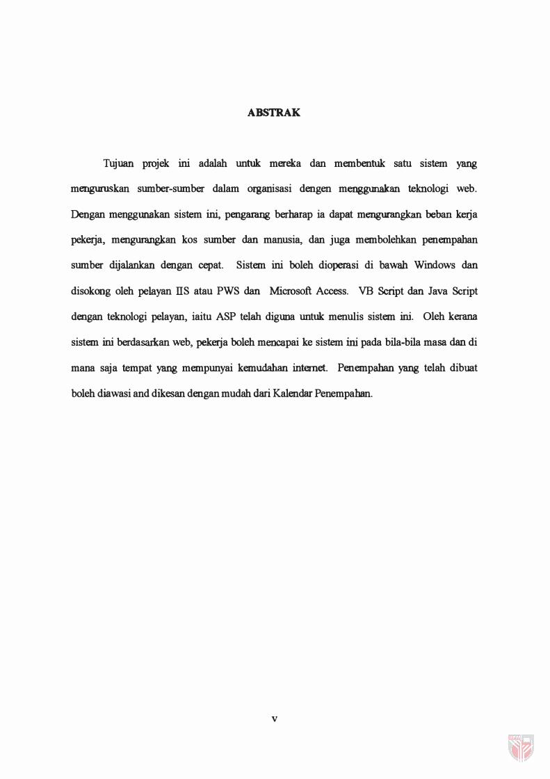
ABSTRAK
Tujuan projek ini adalah untuk mereka dan membentuk satu sistem yang
menguruskan sumber-sumber dalam organisasi dengen menggunakan teknologi web.
Dengan menggunakan sistem ini, pengarang berharap ia dapat mengurangkan beban keIja
pekerja, mengumngkan kos sumber dan manusia, dan juga membolehkan penempaban
sumber dijalankan dengan cepat. Sistem ini boleh dioperasi di bawah Windows dan
disokong oleh pelayan IIS atau PWS dan Microsoft Access. VB Script dan Java Script
dengan teknologi pelayan, iaitu ASP telah digtma untuk menulis sistem ini. Oleh kerana
sistem ini berdasarkan web, pekeIja boleh mencapai ke sistem ini pada bila-bila masa dan di
mana saja tempat yang mempunyai kemudahan internet. Penempahan yang telah dibuat
boleh diawasi and dikesan dengan mudah dari Kalendar Penempahan.
v
TABLE OF CONTENTS
ACKNOWLEDGEMENT ...... '" ...... ...... ...... '" ...... '" ...... ... ... ...... '" ... ... '" ..... .i
LIST OF FIGURES ...... '" ... ... '" ... ...... ... ...... ......... ...... ... ...... ...... ... ...... '" .... .ii
LIST OF TABLES ............ ... ......... ...... ...... '" ...... ... ........ , ...... ... '" ... ... ....... .iii
ABS'TRACT ...... ... ... ........... , ... ...... ......... ... ......... ... .. , ... ... ...... ... ......... ..... . iv
ABSTRAK ... ... ......... ... ... ... ...... ... ... ... ... ...... ... ... ............... ............ ... ......... v
CHAPTER 1 - INTRODUCTION ...................................................................................... 1
1.1 Overview .................................................................................................................... 1
1.2 Problem Statement. ........... . ............ ............................. ......... . .................................. . .. 1
1.3 Objective ........................... . ...................................... .............. .... ............... .............. . .. 2
1.4 Scope of Project. .... . ......................................................... .................................. ..... . .. 3
1.4.1 Web server and server-side technology .. . ........................ ................................ . .. 4
1.4.2 Client-side scripting language .................................................... . .................... . .. 5
1.4.3 Database Management System (DBMS) ..................................... . ...................... 5
CHAPTER 2 - LITERATURE REVIEW .. ........................... ........... ................................... 6
2.1 Facilities Booking System ......... . .................... .. ........ . . ........ .. ......... . .... . ......... . ........ . . .. 6
2.2 Active Server Page (ASP) ......................................... . ........... . ................................... 7
2.3 Database Server ........................................ . ................................................................ 8
CHAPTER 3 - METHODOLOGy ............................ .. ....... ... ........................................... . 10
3.1 Introduction ....................... ... ....................... ............................................................ . 10
3.2 Requirement Analysis .... .. . . . .... . ......... . . . ........ ........................................................... . 12
3.3 Modeling Analysis ....................... ....................................... ... . ............................. ... . 14
3.3.1 Entity Relationship Diagram ............... . ................................... . ........ ...... . ........ . 14
3.3.2 Data Flow Diagram ............................... . ........... . ....................................... ....... . 14
3.4 Software Design ............................................................ ................................... . ...... . 18
3.4.1 Data design .................................................................... .. ................................ . 18
3.4.2 Architectural Design ......................................... . ....................................... . ....... 20
3.4.3 Interface Design ........ . ... ......................... . .............................................. . . ... . ..... . 21
3.4.4 Component-Level Design ................................. . ........................................ ....... 22
3.5 System Coding ................ . ........................................ ............................................... . 23
3.6 System Testing .................. . . ................. . .. .......................................................... ....... 23
3.6.1 Unit testing ...................................... ............. .................. . ................................. . 24
3.6.2 Integration testing ................................... ........... ............ ............ ...................... . 24
3.6.3 Validation testing ....................................................... ...................................... . 24
3.6.4 System testing ..................................................... .............. . . .............................. 24
3.7 Implementation .................... ............. .................. ............ ......................................... 25
CHAP'TER 4 - SYS'TEM MODULES ... .. . . ............ . ............... ........................................... 26
4.1 Introduction .......... ......... . ... . . ......... ........ . .... .. . .. . ......... .............. . .................. ............... 26
4.2 Main Page module ............ .................................................................... ................... 26
4.3 Register module ...... ................. . ..... ...... .... . ........ ..... .... ......................... ..................... 26
4.4 Login module ............................................... . ............ . .. ............... . ........................... . 29
4.5 Booking Calendar module ................................. . .................. .............. ............ ........ . 30
4.6 Add Booking module . . ................... .................. ....................................................... . 32
4.7 EditlDelete Booking module ........ .. .......... . ... ............ .............. . ......... .. . .................... 33
4.8 Bookings Summary module .......... . ........................... .. . ...................... ........... ......... . 34
CHAP'TER 5 - CONCLUSION .. ..... . .... . .... ... ............. . .. .. ... . . .......... ........................... ........ . 36
REFERENCES ................. ..................... ....... ............. ........................... . .............. . ........... . . 37
APPENDIXES ................................................ ................................................................... 38
CHAPTER 1
INTRODUCTION
1.1 Overview
Facilities Booking System is a web-based scheduling system that replaces 'pen &
paper'. The Facilities Booking application efficiently manages shared resources, such as
meeting rooms, equipment and parking spaces. From the desktops, the employees can
quickly view availability of suitable facilities and select an available time window to
book the facilities. In this project, a web-based Facilities Booking System is developed to
manage the shared facilities available in organization. Any user of the network, via the
organization intranet or browse online through internet, can use very simple forms to
enter a Booking Request and look for a suitable time slots in real time Facilities Diaries.
By using this system, it can help the company to minimize inventory losses as we
can easily track or monitor the usage of the resources. It also saves time as bookings can
be done with simple clicks and approval will be notified through email.
1.2 Problem Statement
Facilities available in an organization are inventory for the company. Without
proper management of these shared resources, they will be misused, misplaced or not
being shared out among the users in an organization. This mean that the facilities are
under utilizes. There have been a few cases in AAG where the equipment was misplaced
or spoilt by the users after used. When the next person would like to use it, the equipment
could not be found and company has to buy new unit to replace the lost unit. If this trend
continues, it will be costly to the company as most of the equipments are expensive.
1
Besides the poor maintenance of resources in AAG, there is also no proper
procedure to record the bookings done. Therefore, overlapping in bookings occurred
where a few users booked the same facility at the same time. This will disrupt the
working process of staffs in the company and they will not be able to get their job done
well accordingly.
With the traditional way of booking facilities, the time consumes to getting an
approval from manager for booking the resources are also long. This is due to the routing
of document from one personnel to another personnel. If the personnel have overlooked
the booking request, the applicant will end up waiting for ages.
However, by using the Facilities Booking System, the problems stated above can
be solved. Among the benefits of this system are as below:
• Saves money as we can track resources and people costs
• Helps minimize inventory losses
• Helps reduce operational workload as system will analyze the availability of
facilities or time-slots that was previously done by Manager.
• Saves time as the system reduces problem turn-around time and helps minimize
down time
1.3 Objective
In view of the problems with traditional way of managing facilities , the objectives
of this project is to develop an online Facilities Booking System which serve the
following functions:
i) As a database of facilities available
ii) Ability to let users check the availability of facilities for their booking.
iii) Display real time Facilities Calendar for scheduling each resources
2
iv) Quick notification to users on the outcome of their request for booking.
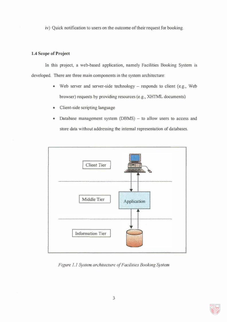
1.4 Scope of Project
In this project, a web-based application, namely Facilities Booking System IS
developed. There are three main components in the system architecture:
• Web server and server-side technology - responds to client (e.g., Web
browser) requests by providing resources (e.g., XHTML documents)
• Client-side scripting language
• Database management system (DBMS) - to allow users to access and
store data without addressing the internal representation of databases.
Client Tier
Middle Tier Application
Information Tier
Figure 1. 1 System architecture of Facilities Booking System
3
1.4.1 Web server and server-side technology
Active Server Page (ASP) is a server side technology which will be used in this
system. It displays dynamic content on the web pages. It is web page that contains
server-side scripts in addition to the usual mixture of text and HfML (Hypertext Markup
Language) tags. Server-side scripts are special commands we put in Web pages that are
processed before pages are sent from our Personal Web Server (PWS) to the Web
browser of someone who's visiting our website. ASP itself isn't a language actually;
instead it uses VBScript or JavaScript to display dynamic content. ASP is more of a
technology used by VBScript / JavaScript on the server side.
To fWl an ASP page, we will need the following system requirement:
• Minimum Windows 95 and above
• Personal Web Server (PWS) for Win95 & Win98 or Internet Information Server
(lIS) for WinNT on the PC.
How ASP works? ASPs are processed by an ActiveX component (i.e., a server
side ActiveX control) called a scripting engine. An ASP file has the file extension .asp
and contains XHTML tags and scripting code. When a server receives a client's HTTP
(HyperText Transfer Protocol) request, the server loads the document (or page) requested
by the client. XHTML document are static documents - all client see the same content
when the document is requested. The ASP processes the request (which often includes
interacting with a database) and returns the results to the client - normally in the form of
an XHfML document, but other data formats (e.g., images, binary, data, etc) can be
retu:rD.ed.
4
1.4.2 Client-side scripting language
In this syMem, the client-side scripting language that will be using is Visual Basic
Script (VBScript). VBScript is a subset of Microsoft Visual Basic® used in World Wide
Web IITML documents to enhance the functionality of a web page displayed in a Web
browser. Microsoft's Internet Explorer Web browser contains a VBScript scripting
engine (i.e., an interpreter) that executes VBScript code.
VBScript is particularly valuable when used with Microsoft Web servers to create
Active Server Pages (ASP). Although other scripting languages can be used, VBScript is
the de facto language for ASP.
1.4.3 Database Management System (DBMS)
A database is an integrated collection of data. Many companies maintain
databases to organize information. Many strategies exist for organizing data to facilitate
access and manipulation. A DBMS provides mechanisms for storing and organizing data
in a manner consistent with the database's format. In this system, Microsoft SQL Server
will be function as the DBMS to store and organize the database.
5
CHAPTER 2
LITERATURE REVIEW
2.1 Facilities Booking System
Managing resources in a company have not always been considered as an
important issue by most of the organization. Even though these resources might be use
daily, many do not realized that they are part of the company asset. And because of this,
many organizations do not have any procedures in recording the usages of their resources,
and even worst is that some of them do not even have any records of what they have!
This is very bad, as company will end up paying extra costs to replace the lost unit. It
will also wasting people costs when employees need to search for the unit, especially
when they are in a rush.
There might also be some exception where some organizations do keep record of
what they own and who have used them. However, these were all done in paper and it
take longer time. The study has shown that whenever employee needs to book or use any
of the resources, they will need to fill in a requisition form in seven days advance and
send it to the administrator. Administrator will then check on the availability of resources
and send the request to the manager to approve the bookings of resources. The whole
process takes a long time and if the administrator overlooks the request, requestors will be
waiting for ages.
In view of this and also the easy-to-get facilities of internet, they are many
Facilities Management System being developed in the market with the objective of
reducing workload, save times and save costs. There are basically two ways in using the
system, as a stand-alone product or a web-based system. The stand-alone product has the
disadvantage of user need to install the system to their computer and all execution needs
6
to be done from the computer installed. However, web-based system provides a more
flexible environment where user can access to the system at anytime and from any place
that have internet access. This is very useful especially for sales person who needs to
travel a lot.
This is why web-based system is gaining popUlarity for most organization while
developing system.
2.2 Active Server Page (ASP)
ASP is the latest server-based technology from Microsoft, designed to create
interactive lITML pages for a World Wide Web \NWW) site, or corporate internet. It is
just of an all encompassing concept called the Active Platform which has been developed
along with Microsoft Windows NT Server and Microsoft Internet Information Server
(lIS). In this project, Microsoft Windows 98 platform and Personal Web Server (PWS)
were used for a small-scale application instead of Microsoft NT server and lIS.
ASP is an open standard web enhancement tool that was developed and
distributed by Microsoft. As such, ASP scripting host is distributed within Microsoft's
web specific products - its web server, lIS and PWS and its specific HfML editors.
ASP is supplied with ActiveX Data Objects (ADO) that provides a high
performance interface to databases that are Open Database Connectivity (ODBC) or OLE
DB compliant.
The beauty of ASP is that ASP scripting host is language-independent. However,
VB Script is the most preferred scripting language for ASP. Another popular scripting
language in the market is Java Script. In order to get the most out of the ASP technology,
combination of both scripting language most probably used. Of course, combination of
more than two scripting language is also allowed.
7
A web application is really no more than a collection of ASP pages and server
components and a website can contain several. The distinction between them is made by
the definition of the application's starting point or root directory within the site. All the
content within this directory and the physical directory structure underneath it is
considered to be part of the application until another application root directory is found.
Each application has its own set of variables and attributes that define its current state,
and these are maintained throughout the lifetime of the application from the moment it is
first run until the end of the last session is closed.
2.3 Database Server
Database Server plays a vital role in internet application development. The
database server is used to store, search and retrieve information that is stored in a
database. This same database that distributes information to web servers can also be
accessed and maintained from corporate walls.
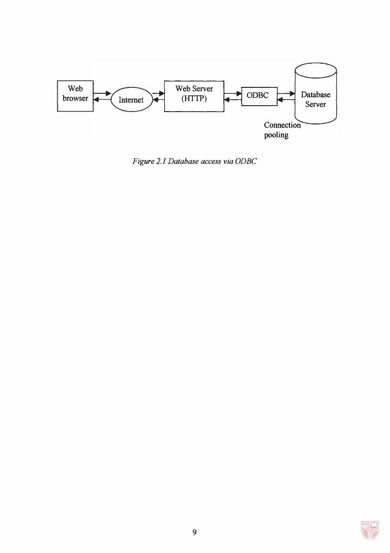
When using the HTTP server as a connection utility to Database Server, there is a
shift in architecture that differs from traditional application development. The new
architecture consists of three components, namely the requesting web browser, the web
server and the Database server, as illustrated in Figure 2.1 . The browser is responsible for
submitting query requests and displaying the results from the database.
The web server is responsible for accepting the query from the browser, creating a
connection to the database, querying the database, formatting the results into HTML and
delivering the HTML back to the requesting browser. The Database Server is responsible
for accepting requests from the web server and delivering the results back to the web
server.
8
Web browser
Web Server (HTTP)
Figure 2.1 Database access via ODBC
9
Server
CHAPTER 3
METHODOLOGY
3.1 Introduction
All software development can be characterized as a problem solving. To solve
this problem, software engineer must incorporate a development strategy that
encompasses the process, methods and tools and the generic phases. This strategy is
often referred to as a process model. A process model for software engineering is chosen
based on the nature of the project and application, the methods and tools to be used, and
the controls and deliverables that are required.
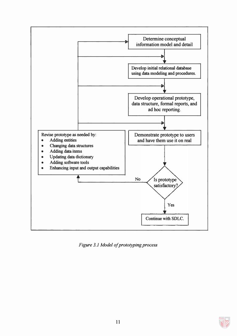
Software development of Facilities Booking System is based on prototyping
model. The prototyping approach to systems development is, in many ways, the very
opposite of an old-style Software Development Life Cycle. Instead of spending a lot of
time producing very detailed specifications, the developers find out only generally what
the users want. The developers do not develop the complete system all at once. Instead
they quickly create the prototype, which either contains portions of the system of most
interest to the users, or is a small-scale working model of the entire system. After
reviewing the prototype with the users, the developers refine and extend it. This process
continues through several iterations until either the users approve the deign or it becomes
apparent that the proposed system cannot meet their needs. If the system is viable, the
developers create a fill-scale version that includes additional features. Figure 3.1 shows a
flow-chart of then prototyping process.
10
Revise prototype as needed by: • Adding entities
• Changing data structures
• Adding data items
• Updating data dictionary
• Adding software tools • Enhancing input and output capabilities
t
... Determine conceptual
information model and detail
•
Develop initial relational database using data modeling and procedures .
.. ...
�r Develop operational prototype,
data structure, formal reports, and ad hoc reporting .
•
Demonstrate prototype to users and have them use it on real
No Is prototype satisfactory?
Yes
� Continue with SOLC.
Figure 3.1 Model o!prototypingprocess
11
In this prototyping process, there are six main phases:
1. Requirements analysis
11. Modeling analysis
111. System design
IV. Coding
v. Testing
VI. Implementation
3.2 Requirement Analysis
Before requirements can be analyzed, modeled or specified, they must be gathered
through an elicitation process. The most commonly used requirement elicitation
technique is to conduct a meeting or interview. As such, an interview has been conducted
on the staff of organization.
To initiate the communication in an interview, a set of questions has been set to
lead to a basic understanding of the problem, the people who want a solution, the nature
of the solution that is desired, and the effectiveness of the first encounter itself The set of
the questions focused on the user, the overall goals and the benefits. Below are the
questions set in the interview conducted for Facilities Booking System:
1. Who is behind the request for this work?
2. Who will use the solution?
3. What are the features require in the solution?
4. Describe the environment in which the solution will be used?
5. Will special performance issues or constraints affect the way the solution
is approached?
6. What are the information require in the solution?
12
7. What will be the economic benefit of a successful solution?
8. What main tasks or functions require by user?
9. What system information will the user acquire, produce or change?
10. Does the user wish to be inform about the unexpected changes?
After the interview has been conducted, the requirements analysis was done and
has identified the following aspects in Facilities Booking System:
• Objectives:
i) Increase the convenience and efficiency of reserving a facility.
ii) Reduce the workload of the facilities administrator.
iii) Maintain control of the booking of facilities by administrator.
• Users:
i) General users (staff) - person who book the facilities
ii) Administrator - person who update the database.
• Requirements,'
� Allowing users wishing to book a facility to browse the schedule, checking the
status of a particular facility at various times, in order to decide upon a particular
facility to reserve for a particular time.
� Allowing users to submit electronically a reservation request for a particular
facility at a particular time.
� The system should have a graphical user interface and should require no training
of requestors and only minimal training of administrators.
� The system should be accessible through the web access.
� The requestors should be able to create or delete any bookings. (It is assumes that
this power will be used to correct mistakes).
13
� Any user should be able to delete any booking that was made or requested by that
user.
3.3 Modeling Analysis
Upon identifying the system and user requirements, a combination of text and
diagram were used to depict the requirements for data, function and behavior in a way
that is easy to understand. The analysis model has three primary objectives:
1. To describe what the user required.
11. To establish a basis for the creation of a software design.
111. To define a set of requirements that can be validated once the software is built.
3.3.1 Entity Relationship Diagram
The entity relationship diagram (ERD) depicts relationships between data objects.
The ERD is the notation that is used to conduct the data modeling activity. Data objects
are represented by a labeled rectangle. Relationships are indicated with a labeled line
connecting objects. The diamond at the connecting lines represents the relationship.
Connections between data objects and relationships are established using a variety
symbols that indicate cardinality and modality.
The ERD diagram for Facilities Booking System is illustrated in Figure 3.2.
3.3.2 Data Flow Diagram
As information moves through software, it is modified by a senes of
transformations. A data flow diagram (DFD) is a graphical representation that depicts
14
Recommended