Technical White Paper for the Unified Control Plane of the SingleBackbone Solution

Technical White Paper for the Unified Control Plane of the SingleBackbone Solution
1 Overview .......................................................................................................................1
2 Model of Unified Control Plane ......................................................................................2
2.1 Peer Model ....................................................................................................................2
2.2 Overlay Model ...............................................................................................................2
2.3 Border Peer Model .........................................................................................................3
3 Key Technologies for a Unified Control Plane .................................................................5
3.1 GMPLS ..........................................................................................................................5
3.1.1 Overview .................................................................................................................................................5
3.1.2 Basic GMPLS Protocols ............................................................................................................................6
3.1.3 Multi-Layer Control .................................................................................................................................6
3.1.4 Related Standards ...................................................................................................................................7
3.2 UNI ...............................................................................................................................7
3.2.1 Overview .................................................................................................................................................7
3.2.2 Basic Functions of UNI .............................................................................................................................9
3.2.3 Relevant Standards ................................................................................................................................12
3.3 PCE .............................................................................................................................13
3.3.1 Overview ...............................................................................................................................................13
3.3.2 PCE Deployment Mode ..........................................................................................................................13
3.3.3 PCE Computation Models ......................................................................................................................16
3.3.4 PCE Discovery and Load Balancing .........................................................................................................19
3.3.5 Communication Between PCCs and PCEs, PCEs and PCEs ......................................................................19
3.3.6 Relevant Standards ................................................................................................................................19
4 Typical Solutions and Application Scenarios .................................................................20
4.1 UNI + Centralized Transport PCE ..................................................................................20
4.2 UNI + Centralized Transport PCE ..................................................................................20
4.3 UNI + Centralized Multi-Layer PCE ...............................................................................21
5 Summary .....................................................................................................................22
6 Acronyms and Abbreviations ........................................................................................23
7 References ...................................................................................................................24
1
1 Overview
The idea of SingleBackbone Solution is IP&OTN Synergy, and there are
3 phases for IP&OTN Synergy: manual synergy, semi-automatic synergy,
Intelligent synergy. During the last two phases, the control plane will play an
important role , because it brings the following changes:
Enables a user to freely apply for bandwidth or release bandwidth. •
Facilitates network management. •
Enables quick and easy service provisioning. •
Enables equipment to provide services at different service level agreements •
(SLAs).
Improves service reliability, by providing various protection recovery •
approaches, which can be used flexibly.
Increases network resource utilization. •
A unified control plane refers to a control plane with integration of various
switching technologies, such as packet switching, timeslot switching,
wavelength switching, and port/fiber switching.
Abstract
This white paper presents details on the technologies relevant to the control
plane involved in the SingleBackbone solution.
Key Words
MPLS, GMPLS, PCE, UNI, ASON, control plane

2
2 Model of Unified Control Plane
Currently in the industry, a unified control plane is presented in three models, that
is, peer model, overlay model, and border peer model. The following sections use
a network with the IP/MPLS layer and optical layer as an example to illustrate
the three models in aspects of features, and their strengths and weaknesses.
2.1 Peer Model
All GMPLS, one domain
NNI
NNINNI
In this model, all nodes run generalized multi-protocol label switching (GMPLS)
to control Layer 3 packets, Layer 2 packets, time division multiplexing (TDM)
services, wavelengths, and even fibers. GMPLS floods the network topology
information to all routers and optical nodes. Then, each node needs to
interpret the topology information and compute paths involving networks
with different switching capabilities based on the topology information. Then,
a label switched path (LSP) can be created to provide an end-to-end path.
This model is a notional model, which has not been allegedly supported by
any supplier. The major challenges for this model are network management,
security, and scalability. In addition, MPLS is mature currently and has been
deployed by router suppliers, making it less likely to change MPLS to GMPLS.
Therefore, MPLS and GMPLS control IP and optical networks, respectively.
This situation cannot be changed in a short term. To achieve an IP & Optical
control plane, interaction between MPLS and GMPLS is essential.
2.2 Overlay Model
In this model, the IP/MPLS network functions as the client layer (clients) and the
optical/GMPLS network functions as the server layer (network). The client layer
and server layer do not exchange routing information in any way. That is to say,
each layer only knows the routing information of that one. To overcome the
3
IP/MPLS
Optical/GMPLS
UNI-C UNI-C
R1 R2
UNIINNI
UNI-N UNI-N
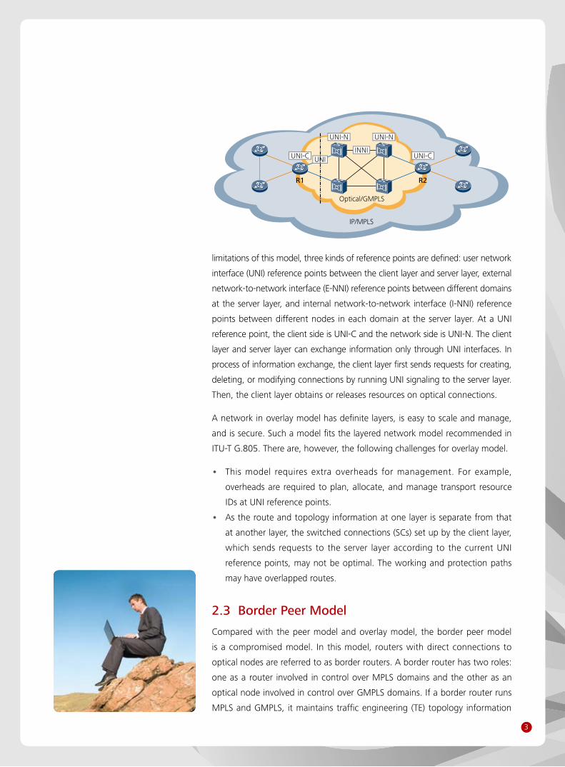
limitations of this model, three kinds of reference points are defined: user network
interface (UNI) reference points between the client layer and server layer, external
network-to-network interface (E-NNI) reference points between different domains
at the server layer, and internal network-to-network interface (I-NNI) reference
points between different nodes in each domain at the server layer. At a UNI
reference point, the client side is UNI-C and the network side is UNI-N. The client
layer and server layer can exchange information only through UNI interfaces. In
process of information exchange, the client layer first sends requests for creating,
deleting, or modifying connections by running UNI signaling to the server layer.
Then, the client layer obtains or releases resources on optical connections.
A network in overlay model has definite layers, is easy to scale and manage,
and is secure. Such a model fits the layered network model recommended in
ITU-T G.805. There are, however, the following challenges for overlay model.
This model requires extra overheads for management. For example, •
overheads are required to plan, allocate, and manage transport resource
IDs at UNI reference points.
As the route and topology information at one layer is separate from that •
at another layer, the switched connections (SCs) set up by the client layer,
which sends requests to the server layer according to the current UNI
reference points, may not be optimal. The working and protection paths
may have overlapped routes.
2.3 Border Peer Model
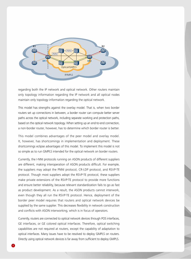
Compared with the peer model and overlay model, the border peer model
is a compromised model. In this model, routers with direct connections to
optical nodes are referred to as border routers. A border router has two roles:
one as a router involved in control over MPLS domains and the other as an
optical node involved in control over GMPLS domains. If a border router runs
MPLS and GMPLS, it maintains traffic engineering (TE) topology information
4
IP/MPLS
Optical/GMPLS
BR1 BR2
R2R1
INNIINNI
regarding both the IP network and optical network. Other routers maintain
only topology information regarding the IP network and all optical nodes
maintain only topology information regarding the optical network.
This model has strengths against the overlay model. That is, when two border
routers set up connections in between, a border router can compute better server
paths across the optical network, including separate working and protection paths,
based on the optical network topology. When setting up an end-to-end connection,
a non-border router, however, has to determine which border router is better.
This model combines advantages of the peer model and overlay model.
It, however, has shortcomings in implementation and deployment. These
shortcomings eclipse advantages of this model. To implement this model is not
so simple as to run GMPLS intended for the optical network on border routers.
Currently, the I-NNI protocols running on ASON products of different suppliers
are different, making interoperation of ASON products difficult. For example,
the suppliers may adopt the PNNI protocol, CR-LDP protocol, and RSVP-TE
protocol. Though most suppliers adopt the RSVP-TE protocol, these suppliers
make private extensions of the RSVP-TE protocol to provide more functions
and ensure better reliability, because relevant standardization fails to go as fast
as product development. As a result, the ASON products cannot interwork,
even though they all run the RSVP-TE protocol. Hence, deployment of the
border peer model requires that routers and optical network devices be
supplied by the same supplier. This decreases flexibility in network construction
and conflicts with ASON interworking, which is in focus of operators.
Currently, routers are connected to optical network devices through POS interfaces,
GE interfaces, or GE colored optical interfaces. Therefore, optical switching
capabilities are not required at routers, except the capability of adaptation to
optical interfaces. Many issues have to be resolved to deploy GMPLS on routers.
Directly using optical network devices is far away from sufficient to deploy GMPLS.
5
3 Key Technologies for a Unified Control Plane
The key technologies for a unified control plane are GMPLS, UNI, and PCE.
This chapter presents details on these key technologies.
3.1 GMPLS
3.1.1 Overview
An ASON is a next-generation optical network, with switching and transport
features, where paths are computed based on user requirements and optical
connections are automatically created, restored, or deleted by means of signaling
control. Unlike a traditional optical network, an ASON has a control plane, which
enables the network to automatically compute paths, create, restore, and delete
optical connections. The control plane for an ASON is based on GMPLS.
GMPLS is based on MPLS. Though GMPLS and MPLS are based on the same set of
protocols (such as RSVP as the signaling protocol and OSPF as the routing protocol),
they greatly differ from each other as they extend the basic protocols. GMPLS is
designed for the control plane and focuses on management of connections;
MPLS is designed for the data plane and focuses on transport of data streams.
Originally, GMPLS is intended to apply MPLS to control wavelength switching.
Currently, GMPLS has extended to fiber/port switching, wavelength switching (WDM
and G.709 OTN), timeslot switching (TDM), Layer 2 switching (Ethernet, ATM, and
frame relay), and packet switching (MPLS and MPLS-TP). With a design to support
different network technologies, GMPLS can control both an optical network and
an MPLS data network. An optical network can be considered as a transport plane
controled and managed by GMPLS and an MPLS data network as a data plane also
controled and managed by GMPLS. Unlike MPLS, GMPLS has the following features:
Separate control channel and data channel: A fault on the control channel •
does not affect data transmission over the data channel.
Bidirectional LSP: A bidirectional LSP can be set up in only one signaling process. •
Link-level protection: GMPLS diffuses and uses the protection capabilities •
of links (such as 1+1, 1:1, and ring protection).
Bandwidth allocation by priority: Bandwidth resources are allocated by priority. •
Shared risk link group (SRLG): Paths for a service under 1+1 protection can •
include links in different SRLGs. This improves service reliability.
6
Multi-layer network control: A multi-layer network, such as IP over SDH •
over WDM, IP over OXC over WDM, or IP over DWDM network, can be
controlled in a unified manner.
On the control plane, GMPLS enables the following functions:
Auto-discovery of resources: Available resources on a network are •
automatically discovered and resource information is automatically updated.
Route control: GMPLS automatically discovers and updates the network •
topology, provisions routes, calculates service paths, and provides traffic
engineering (TE).
Connection management: GMPLS enables end-to-end connections for •
services, as well as creation, query, modification, deletion, protection, and
restoration of the connections.
3.1.2 Basic GMPLS Protocols
The common control and measure plane (CCAMP) workgroup of IETF studies
and defines GMPLS-related protocols, which are based on extensions of
protocols related to MPLS-TE. These GMPLS-related protocols can be classified
into link management protocols, routing protocols, and signaling protocols.
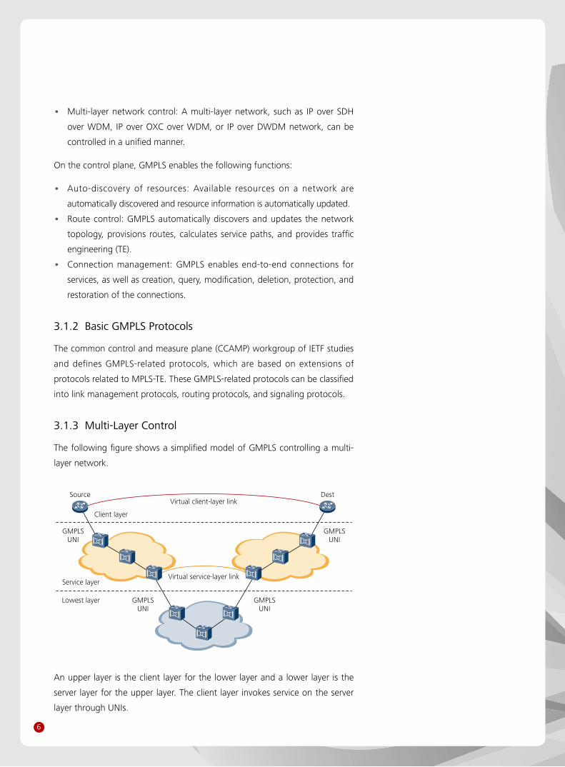
3.1.3 Multi-Layer Control
The following figure shows a simplified model of GMPLS controlling a multi-
layer network.
Source
Service layer
Lowest layer
DestVirtual client-layer link
Client layer
Virtual service-layer link
GMPLSUNI
GMPLSUNI
GMPLSUNI
GMPLSUNI
An upper layer is the client layer for the lower layer and a lower layer is the
server layer for the upper layer. The client layer invokes service on the server
layer through UNIs.
7
For multi-layer control, there are three methods to express and compute the
multi-layer paths:
LSPs at the server layer are advertised as virtual TE links at the client layer. •
The TE topology at the server layer is not visible to the client layer and
LSPs at the server layer are expressed by link at the client layer. The TE
topology at the client layer is a virtual topology. This approach is simple
and fits the layer network model. In this approach, LSPs are easy to
manage but optimal end-to-end LSPs cannot be computed.
The client layer shares the TE topology view of the server layer. That is, •
the TE topology at the server layer is visible to the client layer. Then, the
client layer can compute end-to-end paths according to the topologies
at the client layer and server layer. In this approach, optimal paths can be
computed, but resources at the server layer may be wasted. In addition,
links must be advertised as links with multiple switching capabilities.
Another optional approach is PCE. In this approach, there is a centralized •
PCE at each layer and PCEs at these layers coordinate with each other
to compute multi-layer paths. For more information regarding PCE, see
section 4.3 "UNI + Centralized Multi-Layer PCE."
3.1.4 Related Standards
Currently, GMPLS-related standards are mature and they are:
IETF, RFC 3945, RFC 3471, RFC 3473, RFC 3209, RFC 4139, RFC 4202, RFC
4203, RFC 4258, RFC 4204, RFC 4209, RFC 4872, RFC 4873, RFC 5212
3.2 UNI
3.2.1 Overview
In the late 1990s, certain telecommunication equipment suppliers showcased
their ASON products, which, however, were based on different signaling
protocols, such as CR-LDP, PNNI, and RSVP-TE. To ensure internetworking
between these ASON products, certain suppliers and operators established
the optical internetworking forum (OIF), which focused on standardization
and testing related to internetworking. Since 2001, the OIF has successfully
organized many internetworking tests and released relevant standards. For
more information regarding history of the OIF, see the following table.
After years of development, the OIF UNI standard has been mature and the
major optical network equipment suppliers, including Huawei, also support
OIF UNI. The OIF UNI protocol is based on the IETF RSVP protocol, with the
8
former extending the later. Now, OIF UNI has not been acknowledged by
the IETF and the IETF even presents GMPLS UNI. Therefore, there are two
UNI protocols. One is OIF UNI stipulated by the OIF and the other is GMPLS
UNI stipulated by the IETF. Major router suppliers support GMPLS UNI, most
optical network equipment suppliers support OIF UNI, and certain other
suppliers, including Huawei, support both.
Currently, internetworking of GMPLS UNI is demonstrated on MPLS
2004/2005/2006, or iPOP 2005/2006 held by ISOCORE with focus on data
or IP & Optical synergy. Internetworking of OIF UNI and GMPLS UNI is also
demonstrated on iPOP.
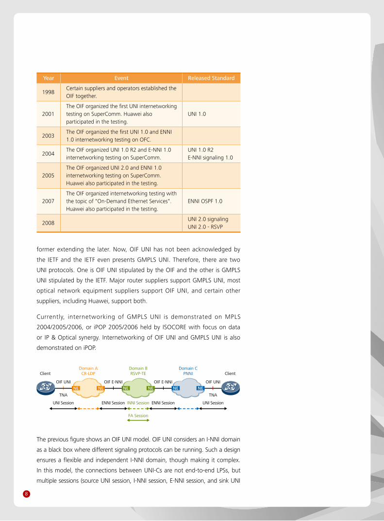
Year Event Released Standard
1998Certain suppliers and operators established the OIF together.
2001The OIF organized the first UNI internetworking testing on SuperComm. Huawei also participated in the testing.
UNI 1.0
2003The OIF organized the first UNI 1.0 and ENNI 1.0 internetworking testing on OFC.
2004The OIF organized UNI 1.0 R2 and E-NNI 1.0 internetworking testing on SuperComm.
UNI 1.0 R2E-NNI signaling 1.0
2005The OIF organized UNI 2.0 and ENNI 1.0 internetworking testing on SuperComm. Huawei also participated in the testing.
2007The OIF organized internetworking testing with the topic of "On-Demand Ethernet Services". Huawei also participated in the testing.
ENNI OSPF 1.0
2008UNI 2.0 signalingUNI 2.0 - RSVP
Client
UNI Session
OIF UNI OIF UNIOIF E-NNI OIF E-NNI
TNA TNA
UNI SessionENNI Session ENNI Session
ClientDomain A
CR-LDPDomain BRSVP-TE
INNI Session
FA Session
Domain CPNNI
NE NE NE NENENE
The previous figure shows an OIF UNI model. OIF UNI considers an I-NNI domain
as a black box where different signaling protocols can be running. Such a design
ensures a flexible and independent I-NNI domain, though making it complex.
In this model, the connections between UNI-Cs are not end-to-end LPSs, but
multiple sessions (source UNI session, I-NNI session, E-NNI session, and sink UNI
9
session). OIF UNI defines a TNA address for a UNI interface. This requires special
configuration management and extension of OSPF to flood the reachability
information of TNA addresses.
Client
GMPLS UNI GMPLS UNI
LSP Stitching
GMPLS GMPLS
E2E Session
ClientDomain BRSVP-TE
Domain CRSVP-TE
Domain ARSVP-TE
FA Session FA SessionFA Session
NENE NENENENE
The previous figure shows a GMPLS UNI model. In this model, the address
space and addressing approach used at a UNI interface are the same as those
for the network domain. The RSVP-TE protocol is used as UNI signaling, I-NNI
signaling, and E-NNI signaling. Connections between UNI-Cs are end-to-end
LSPs, and thus there is only one RSVP session.
Implementation of GMPLS UNI, however, is not that simple. Though most
ASON equipment suppliers choose RSVP-TE, standardization (especially in the
aspect of protection restoration) lags behind product development. Therefore,
the suppliers extend the protocol to satisfy their own requirements. In this
manner, the relevant functions and features also differ from each other,
making I-NNI internetworking difficult. Consequently, conversion between
standard objects and non-standard objects is essential at a UNI-N node.
3.2.2 Basic Functions of UNI
With the help of UNI, a user can freely send a request for creating or deleting
a connection to a transmission network, through a UNI interface. The
requested connections can be either unidirectional or bidirectional, and can
be SDH/SONET connections, OTN connections, or Ethernet connections.
Call Control
UNI has the call control function.
Calls refer to association relationships between end nodes or key transport
nodes (such as border nodes on a network). One call supports one instance
of user service. A call itself does not ensure connectivity of the link for user
service transmission, but only builds the association relationships between
one or more connections. Calls also refer to contractual relationships between
end nodes, and are used to manage a group of connections, simply and
easily. This group of connections provide end-to-end data transfer service for
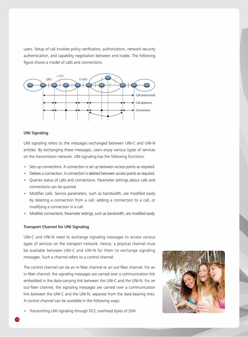
10
users. Setup of call involves policy verification, authorization, network security
authentication, and capability negotiation between end nodes. The following
figure shows a model of calls and connections.
UNI E-NNI
Call (end-to-end)
Call segments
Connections
I-NNI
UNI Signaling
UNI signaling refers to the messages exchanged between UNI-C and UNI-N
entities. By exchanging these messages, users enjoy various types of services
on the transmission network. UNI signaling has the following functions:
Sets up connections. A connection is set up between access points as required. •
Deletes a connection. A connection is deleted between access points as required. •
Queries status of calls and connections. Parameter settings about calls and •
connections can be queried.
Modifies calls. Service parameters, such as bandwidth, are modified easily •
by deleting a connection from a call, adding a connection to a call, or
modifying a connection in a call.
Modifies connections. Parameter settings, such as bandwidth, are modified easily. •
Transport Channel for UNI Signaling
UNI-C and UNI-N need to exchange signaling messages to access various
types of services on the transport network. Hence, a physical channel must
be available between UNI-C and UNI-N for them to exchange signaling
messages. Such a channel refers to a control channel.
The control channel can be an in-fiber channel or an out-fiber channel. For an
in-fiber channel, the signaling messages are carried over a communication link
embedded in the data-carrying link between the UNI-C and the UNI-N. For an
out-fiber channel, the signaling messages are carried over a communication
link between the UNI-C and the UNI-N, separate from the data-bearing links.
A control channel can be available in the following ways:
Transmitting UNI signaling through DCC overhead bytes of SDH •
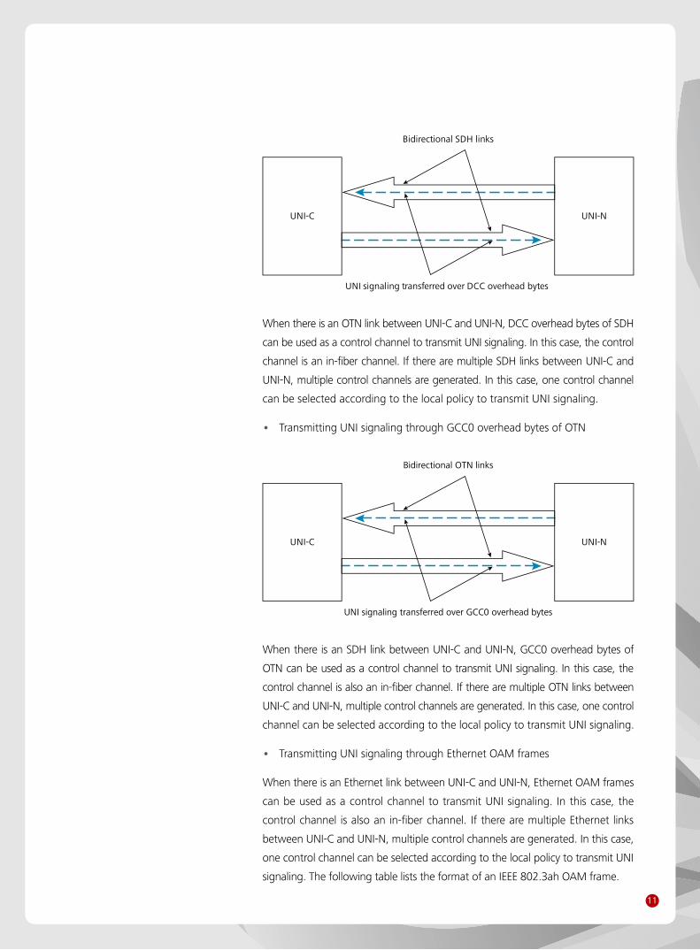
11
Bidirectional SDH links
UNI signaling transferred over DCC overhead bytes
UNI-C UNI-N
When there is an OTN link between UNI-C and UNI-N, DCC overhead bytes of SDH
can be used as a control channel to transmit UNI signaling. In this case, the control
channel is an in-fiber channel. If there are multiple SDH links between UNI-C and
UNI-N, multiple control channels are generated. In this case, one control channel
can be selected according to the local policy to transmit UNI signaling.
Transmitting UNI signaling through GCC0 overhead bytes of OTN •
Bidirectional OTN links
UNI signaling transferred over GCC0 overhead bytes
UNI-C UNI-N
When there is an SDH link between UNI-C and UNI-N, GCC0 overhead bytes of
OTN can be used as a control channel to transmit UNI signaling. In this case, the
control channel is also an in-fiber channel. If there are multiple OTN links between
UNI-C and UNI-N, multiple control channels are generated. In this case, one control
channel can be selected according to the local policy to transmit UNI signaling.
Transmitting UNI signaling through Ethernet OAM frames •
When there is an Ethernet link between UNI-C and UNI-N, Ethernet OAM frames
can be used as a control channel to transmit UNI signaling. In this case, the
control channel is also an in-fiber channel. If there are multiple Ethernet links
between UNI-C and UNI-N, multiple control channels are generated. In this case,
one control channel can be selected according to the local policy to transmit UNI
signaling. The following table lists the format of an IEEE 802.3ah OAM frame.

12
Field Size in Octets
Fields in MAC Frame
Value (s)
6Destination Address
0x01-80-C2-00-00-02 (Slow_Protocols_Multicast address)
6 Source Address UNI 1.0
2 Type/Length
1 Subtype 0x88-09 (Slow_Protocols_Type field value)
2 Flags 0x03 (OAM)
1 Code
3Data/Pad
0xFE (vendor unique)
39-1493 0x00-0F-10 (OIF OUI)
4 FCSData – IP packet as described in the protocol-specific IA
The data field in an OAM frame can be used to carry UNI signaling messages.
When there are multiple logical Ethernet ports at a UNI interface, an Ethernet
port must be specified to transmit signaling messages.
Transmitting UNI signaling through an external IP transmission network •
Bidirectional data links
UNI signaling transmitted through anexternal IP transmission network
IP transmissionnetwork
UNI-C UNI-N
UNI signaling can also be transmitted through an external IP transmission
network. In this case, the control channel is an out-fiber channel.
Transmitting UNI signaling through an exclusive signaling channel •
A bidirectional connection can be set up between UNI-C and UNI-N to exclusively
transmit UNI signaling. In this case, the control channel is an out-fiber channel.
3.2.3 Relevant Standards
Currently, the UNI-relevant standards are as follows:
IETF: RFC 4208, RFC 4974 •
OIF: OIF-UNI-01.0-R2-Common, OIF-UNI-01.0-R2-RSVP, OIF-UNI-02.0- •
Common, OIF-UNI-02.0-RSVP
13
3.3 PCE
3.3.1 Overview
On an MPLS or GMPLS network, paths must be computed based on constraints
to achieve traffic engineering. On a large network, path computation based
on constraints is complex and requires powerful computation capabilities on
relevant elements. If distributed path computation is used, each node must
have powerful capabilities of path computation, leading to high costs at each
node. On a multi-domain network, the topology of each domain is not visible
to other domains. Therefore, to compute optical end-to-end multi-domain
paths, the path computation elements in these domains must collaborate
with each other to compute optimal multi-domain paths. PCE is such a path
computation technology intended to satisfy the preceding requirements.
A PCE has powerful computation capabilities. The PCE function can be deployed
on either a network node or an external server. A PCE is responsible for path
computation in one domain. Path computation requests in each domain can be
sent to the PCE in the domain. After finishing path computation, the PCE sends the
computation results to the requester or path computation client (PCC). Multiple
PCEs, when collaborating with each other, can compute optical multi-domain
paths. A domain in this document may be one or multiple IGP areas or ASs.
3.3.2 PCE Deployment Mode
A PCE can be deployed in various modes.
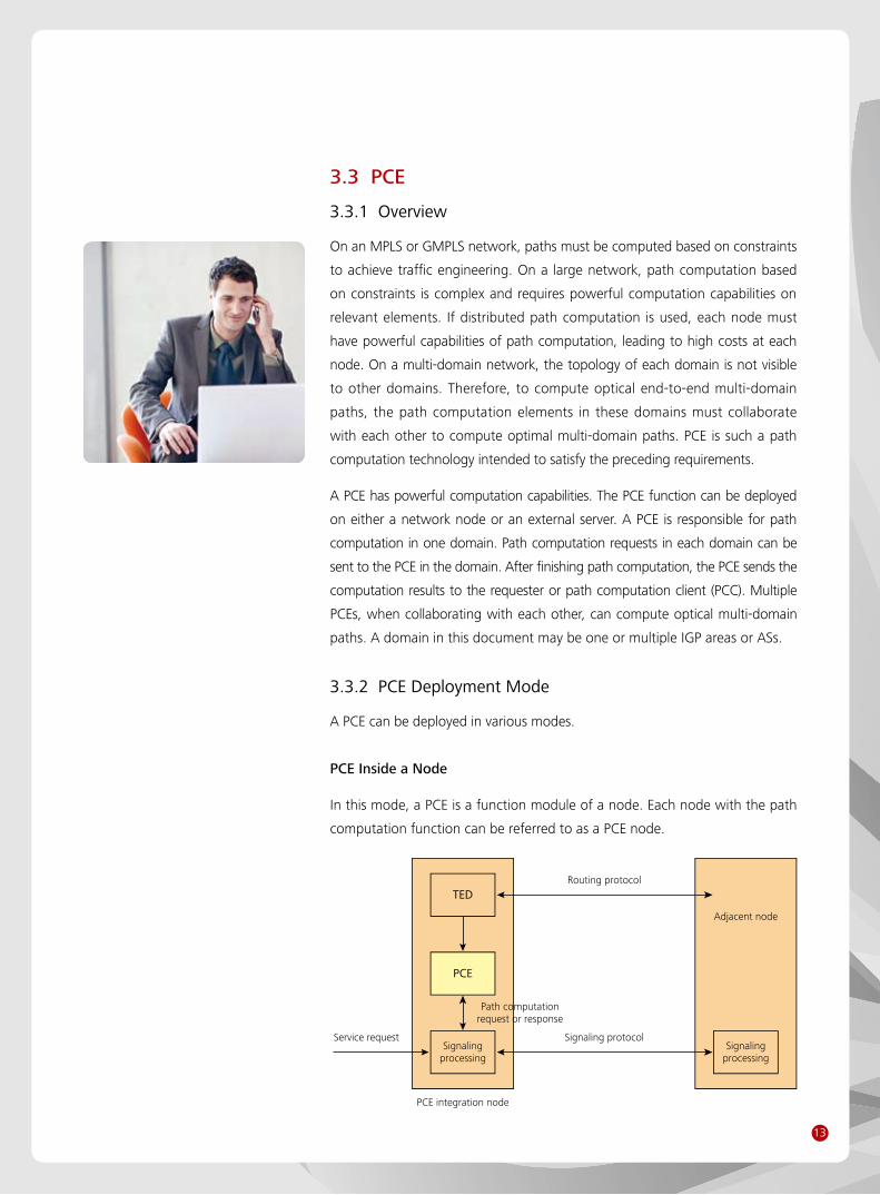
PCE Inside a Node
In this mode, a PCE is a function module of a node. Each node with the path
computation function can be referred to as a PCE node.
PCE
Signalingprocessing
Path computationrequest or response
Routing protocol
Signaling protocolService request
PCE integration node
Adjacent node
Signalingprocessing
TED
14
The preceding figure shows a typical centralized PCE node. This node exchanges
TE information with an adjacent node by running a routing protocol and saves the
TE information in TED. When receiving a request for establishing a TE LSP, the node
asks the PCE to compute a path. After the PCE finishes path computation, the node
receives the path computation result and triggers the signaling process to send
signaling messages with the request for establishing a TE LSP to a downstream node.
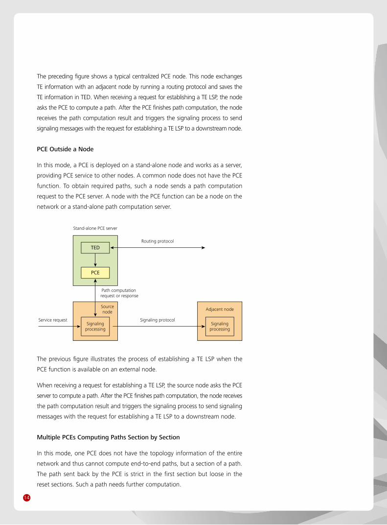
PCE Outside a Node
In this mode, a PCE is deployed on a stand-alone node and works as a server,
providing PCE service to other nodes. A common node does not have the PCE
function. To obtain required paths, such a node sends a path computation
request to the PCE server. A node with the PCE function can be a node on the
network or a stand-alone path computation server.
PCE
Signalingprocessing
Path computation request or response
Adjacent nodeSourcenode
Signalingprocessing
Routing protocol
Signaling protocolService request
Stand-alone PCE server
TED
The previous figure illustrates the process of establishing a TE LSP when the
PCE function is available on an external node.
When receiving a request for establishing a TE LSP, the source node asks the PCE
server to compute a path. After the PCE finishes path computation, the node receives
the path computation result and triggers the signaling process to send signaling
messages with the request for establishing a TE LSP to a downstream node.
Multiple PCEs Computing Paths Section by Section
In this mode, one PCE does not have the topology information of the entire
network and thus cannot compute end-to-end paths, but a section of a path.
The path sent back by the PCE is strict in the first section but loose in the
reset sections. Such a path needs further computation.
15
Path computationrequest or response
Path computationrequest or response
Signalingprocessing
Servicerequest
Signalingprotocol
Signalingprotocol
Stand-alone PCE server
Source node Intermediate node Adjacent node
Stand-alone PCE server
PCE
Signalingprocessing
TED
PCE
Signalingprocessing
TED
As shown in the previous figure, when receiving a request for establishing
a TE LSP, the source node asks the first PCE to compute a path. This PCE
computes only a section of a path and sends the path section to the source
node. When receiving the path section, the source node triggers the signaling
process and sends signaling messages with a request for establishing a TE LSP
to a downstream node. When the signaling messages reach an intermediate
node (for path re-computation), the intermediate node asks the second PCE
to compute the rest sections of the path. When finishing path computation,
the intermediate node continues the signaling process and sends signaling
messages with a request for establishing a TE LSP to a downstream node.
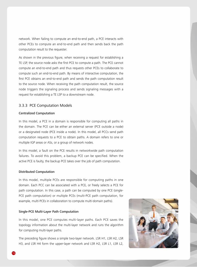
Multiple PCEs Computing Complete Paths Together
In this mode, a PCE does not have the topology information about the entire
Path computationrequest or response
Signalingprocessing
Servicerequest
Signalingprotocol
Signalingprotocol
Stand-alone PCE server
Source node Intermediate node Adjacent node
Stand-alone PCE server
PCE
Signalingprocessing
TED
Signalingprocessing
PCE
TED
PCE communication protocol
16
network. When failing to compute an end-to-end path, a PCE interacts with
other PCEs to compute an end-to-end path and then sends back the path
computation result to the requester.
As shown in the previous figure, when receiving a request for establishing a
TE LSP, the source node asks the first PCE to compute a path. The PCE cannot
compute an end-to-end path and thus requests other PCEs to collaborate to
compute such an end-to-end path. By means of interactive computation, the
first PCE obtains an end-to-end path and sends the path computation result
to the source node. When receiving the path computation result, the source
node triggers the signaling process and sends signaling messages with a
request for establishing a TE LSP to a downstream node.
3.3.3 PCE Computation Models
Centralized Computation
In this model, a PCE in a domain is responsible for computing all paths in
the domain. The PCE can be either an external server (PCE outside a node)
or a designated node (PCE inside a node). In this model, all PCCs send path
computation requests to a PCE to obtain paths. A domain refers to one or
multiple IGP areas or ASs, or a group of network nodes.
In this model, a fault on the PCE results in networkwide path computation
failures. To avoid this problem, a backup PCE can be specified. When the
active PCE is faulty, the backup PCE takes over the job of path computation.
Distributed Computation
In this model, multiple PCEs are responsible for computing paths in one
domain. Each PCC can be associated with a PCE, or freely selects a PCE for
path computation. In this case, a path can be computed by one PCE (single-
PCE path computation) or multiple PCEs (multi-PCE path computation, for
example, multi-PCEs in collaboration to compute multi-domain paths).
Single-PCE Multi-Layer Path Computation
In this model, one PCE computes multi-layer paths. Each PCE saves the
topology information about the multi-layer network and runs the algorithm
for computing multi-layer paths.
The preceding figure shows a simple two-layer network. LSR H1, LSR H2, LSR
H3, and LSR H4 form the upper-layer network and LSR H2, LSR L1, LSR L2,

17
LSRL1
LSRL2
LSRH1
LSRH2
LSRH3
LSRH4
PCE
and LSR H3 form the lower-layer network. A PCE saves topology information
about the two layers of networks and thus can compute end-to-end multi-
layer paths. For example, to compute a path from LSR H1 to LSR H4, a PCE
computes the H1-H2-L1-L2-H3-H4 path according to the network topology
information. The H2-L1-L2-H3 section of the path is at the lower layer. After
connections are set up along the section, a TE link can be advertised to the
upper layer and then connections at the upper layer can be set up.
Multi-Layer PCE Path Computation
In this model, one PCE does not save the topology information about all layers.
A PCE at each layer is responsible for computing paths at the layer. To compute
end-to-end multi-layer paths, multiple PCEs need to collaborate with each other.
LSRL1
LSRL2
LSRH1
LSRH2
LSRH3
LSRH4
PCEHi
PCELo
The previous figure shows a multi-layer network. Assume that PCE Hi is
responsible for computing paths at the upper layer and PCE Lo is responsible
for computing paths at the lower layer. Then, the process for computing a
path from layer H1 to layer H4 is as follows:
LSR H1 sends a request for computing an H1-to-H4 path to PCE Hi. •
PCE Hi selects H2 or H3 as an ingress or egress node on the network at the •
lower layer.
18
PCE Hi requests PCE Lo to compute an H2-to-H3 path. •
PCE Lo returns the H2-L1-L2-H3 path to PCE Hi. •
PCE Hi computes the H1-H2-L1-L2-H3-H4 end-to-end path and sends the •
path back to LSR H1.
The PCEs at the upper and lower layers may not interact. In this case, the PCE
at the upper layer computes paths at the upper layer and signaling carries
information about upper-layer paths to set up connections. When signaling
reaches the ingress node on the lower-layer network, the ingress node
requests the PCE at the lower layer to compute paths at the lower layer and
to set up connections along the lower-layer path. After connections at the
lower layer are set up, the connections are used as links at the upper layer
and thus forwarding upper-layer signaling can continue.
When the network consists of three or more layers, the models of "single PCE for
computation of multi-layer paths" and "multi-layer PCEs for path computation"
can be used together. For example, on an MPLS-SDH-OTN network, an upper-
layer PCE is responsible for computing paths on the MPLS network and a lower-
layer PCE is responsible for computing paths on the SDH and OTN networks.
Synchronous or Asynchronous Path Computation
Sometimes to provision a service, such as a service under 1+1 protection,
multiple paths must be computed.
When multiple paths need to be computed, a PCC can send multiple stand-
alone requests to a PCE to compute multiple paths or one request to a PCE
to compute a group of paths. A PCC can specify synchronous computation or
asynchronous computation in a path computation request sent to a PCE.
In the case of synchronous computation, a PCE computes a group of paths
(paths up to certain constraints, such as mutual separation) and places the
path group in one or multiple response messages sent back to the PCC.
In the case of asynchronous computation, a PCE considers multiple requests
from multiple stand-alone request messages or one message as stand-alone
requests for path computation and places the path computation results stand-
alone response messages sent to the PCC or places multiple computation
results in one response message sent to the PCC.
In the case of synchronous path computation, multiple paths are computed
according to constraints on these paths, such as path separation. In the case
of asynchronous path computation, stand-alone path computation requests
19
are processed without any constraint being considered. Hence, synchronous
path computation is better than asynchronous path computation, but the
former is less efficient than the latter.
3.3.4 PCE Discovery and Load Balancing
A PCC does not broadcast a request message to all PCEs on the network, waiting
for response from a PCE. Instead, a PCC sends a request message to a designated
PCE. Therefore, a PCC needs to know from which PCE it can obtain path
information and relevant information about such a PCE, such as addresses. A PCC
can discover PCEs according to static configuration or by running a protocol.
When multiple PCEs are available for a PCC, a PCE is selected according to
the information about the PCEs and the local policy. When multiple PCEs are
available, a computation task can be executed by multiple PCEs together. In
this manner, the workload of path computation is evenly loaded on the PCEs.
For example, each PCE has its own computation capability or saves topology
information about different domains.
3.3.5 Communication Between PCCs and PCEs, PCEs and PCEs
When the PCE function is deployed inside a node, a communication protocol
(PCE CP) does not need to be defined between a PCC and a PCE. Instead, only
internal interface communication needs to be defined. If a PCC and a PCE are
at different nodes, they need to communicate with each other by running a
protocol (for path computation requests and responses). When multiple PCEs
compute multi-domain paths together, PCEs also need to communicate with
each other by running a protocol. When one PCE sends a path computation
request to another PCE, the latter considers the former as a PCC.
A PCE CP enables a PCC to send a path computation request message to
a PCE and a PCE to send a path computation response message to a PCC.
When path computation is successful, a PCE sends the path information
back to the PCC. When path computation fails, a PCE sends back a response
message to a PCC, indicating the probable cause of the failure whenever
possible.
3.3.6 Relevant Standards
Currently, PCE-relevant standards are mature and they are:
IETF, RFC 4655, RFC 4657, RFC 4674, RFC 4927, RFC 5440, RFC 5089, RFC
5088, RFC 5541, RFC 5557, RFC 5520, RFC 5521, RFC 5394
20
4 Typical Solutions and Application Scenarios
The solution of UNI + PCE is applicable to control of a network with an IP/
MPLS layer and optical/GMPLS layer. The IP/MPLS network and optical/GMPLS
network interact with each other through UNI interfaces. A PCE can be
deployed to achieve computation of paths involving the two layers.
4.1 UNI + Centralized Transport PCE
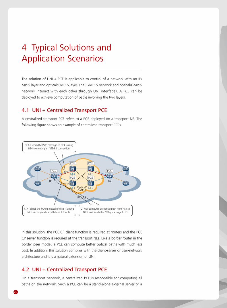
A centralized transport PCE refers to a PCE deployed on a transport NE. The
following figure shows an example of centralized transport PCEs.
2. NE1 computes an optical path from NE4 to NE3, and sends the PCRep message to R1.
3. R1 sends the Path message to NE4, askingNE4 to creating an NE3-R2 connection.
1. R1 sends the PCReq message to NE1, asking NE1 to computate a path from R1 to R2.
IP/MPLS
Optical/GMPLS
NE4 NE3
NE1 NE2
R1 R2
PCC PCC
PCE PCE
PCE PCE
In this solution, the PCE CP client function is required at routers and the PCE
CP server function is required at the transport NEs. Like a border router in the
border peer model, a PCE can compute better optical paths with much less
cost. In addition, this solution complies with the client-server or user-network
architecture and it is a natural extension of UNI.
4.2 UNI + Centralized Transport PCE
On a transport network, a centralized PCE is responsible for computing all
paths on the network. Such a PCE can be a stand-alone external server or a
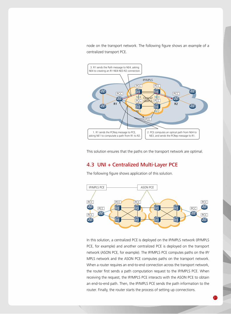
21
2. PCE computes an optical path from NE4 to NE3, and sends the PCRep message to R1.
3. R1 sends the Path message to NE4, askingNE4 to creating an R1-NE4-NE3-R2 connection.
1. R1 sends the PCReq message to PCE, asking NE1 to computate a path from R1 to R2.
IP/MPLS
Optical/GMPLS
NE4 NE3
NE1 NE2
R1 R2
PCC PCC
PCC PCC
PCC PCC
PCE
node on the transport network. The following figure shows an example of a
centralized transport PCE.
PCC
IP/MPLS PCE ASON PCE
PCC PCC
PCC
PCC
PCC
PCC PCC
In this solution, a centralized PCE is deployed on the IP/MPLS network (IP/MPLS
PCE, for example) and another centralized PCE is deployed on the transport
network (ASON PCE, for example). The IP/MPLS PCE computes paths on the IP/
MPLS network and the ASON PCE computes paths on the transport network.
When a router requires an end-to-end connection across the transport network,
the router first sends a path computation request to the IP/MPLS PCE. When
receiving the request, the IP/MPLS PCE interacts with the ASON PCE to obtain
an end-to-end path. Then, the IP/MPLS PCE sends the path information to the
router. Finally, the router starts the process of setting up connections.
This solution ensures that the paths on the transport network are optimal.
4.3 UNI + Centralized Multi-Layer PCE
The following figure shows application of this solution.

22
5 Summary
In summary, the unified control plane of SingleBackbone Solution adopts
the overlay model, which is an open architecture. And the key technologies
include GMPLS, UNI, PCE. With the trend of intelligent network, the unified
control plane will be more and more important to SingleBackbone Solution.
More detailed information of SingleBackbone Solution, you can refer to the
Technical White Paper for the SingleBackbone Solution.
http://www.huawei.com/broadband/iptime_backbone_solution.do

23
6 Acronyms and Abbreviations
ABR Area Border Router
ARPU Average Revenue Per User
AS Autonomous System
ASBR Autonomous System Boundary Router
ASON Automatically Switched Optical Network
CAPEX CAPital EXpenditure
CR-LDP Constraint-based Routed-Label Distribution Protocol
E-NNI External Network-to-Network Interface
ERO Explicit Route Object
FRR Fast Reroute
GMPLS Generalized Multi-Protocol Label Switching
IETF Internet Engineering Task Force
I-NNI Internal Network-to-Network Interface
ITU International Telecommunication Union
LMP Link Management Protocol
LSP Label Switched Path
MPLS Multi-Protocol Label Switching
NNI Network-to-Network Interface
OIF Optical Internetworking Forum
OPEX OPerational EXpenditure
OSPF Open Shortest Path First
OTN Optical Transport Network
PCC Path Computation Client
PCE Path Computation Element
PCECP Path Computation Element Communication Protocol
RSVP Resource ReSerVation Protocol
SC Switched Connection
SRLG Shared Risk Link Group
TDM Time Division Multiplexing
TE Traffic Engineering
TED Traffic Engineering Database
UNI User-Network Interface
UNI-C User-Network Interface-Client
UNI-N User-Network Interface-Network
WDM Wavelength Division Multiplexing
24
7 References
IETF, RFC 3945, Generalized Multi-Protocol Label Switching (GMPLS) •
Architecture
IETF, RFC 3471, Generalized Multi-Protocol Label Switching (GMPLS) •
Signaling Functional Description
IETF, RFC 3473, Generalized Multi-Protocol Label Switching (GMPLS) •
Signaling Resource ReserVation Protocol-Traffic Engineering (RSVP-TE)
Extensions
IETF, RFC 3209, RSVP-TE: Extensions to RSVP for LSP Tunnel •
IETF, RFC 4139, Requirements for Generalized MPLS (GMPLS) Signaling •
Usage and Extensions for Automatically Switched Optical Network (ASON)
IETF, RFC 4202, Routing Extensions in Support of GMPLS •
IETF, RFC 4203, OSPF Extensions in Support of Generalized Multi-Protocol •
Label Switching (GMPLS)
IETF, RFC 4258, Requirements for Generalized Multi-Protocol Label •
Switching (GMPLS) Routing for the Automatically Switched Optical
Network (ASON)
IETF, RFC 4204, Link Management Protocol (LMP) •
IETF, RFC 4209, Link Management Protocol (LMP) for Dense Wavelength •
Division Multiplexing (DWDM) Optical Line Systems
IETF, RFC 4872, RSVP-TE Extensions in Support of End-to-End Generalized •
Multi-Protocol Label Switching (GMPLS) Recovery
IETF, RFC 4873, GMPLS Segment Recovery •
IETF, RFC 5212, Requirements for GMPLS-Based Multi-Region and Multi- •
Layer Networks (MRN/MLN)
IETF, RFC 4208, Generalized Multiprotocol Label Switching (GMPLS) User- •
Network Interface (UNI): Resource ReserVation Protocol-Traffic Engineering
(RSVP-TE) Support for the Overlay Model
IETF, RFC 4974, Generalized MPLS (GMPLS) RSVP-TE Signaling Extensions •
in Support of Calls
OIF, OIF-UNI-01.0, User Network Interface (UNI) 1.0 Signaling Specification •
OIF, OIF-UNI-01.0-R2-Common, User Network Interface (UNI) 1.0 •
Signaling Specification, Release 2: Common Part
OIF, OIF-UNI-01.0-R2-RSVP, RSVP Extensions for User Network Interfaces •
(UNI) 1.0 Signaling, Release 2
OIF, OIF-UNI-02.0-Common, User Network Interface (UNI) 2.0 Signaling •
Specification: Common Part
25
OIF, OIF-UNI-02.0-RSVP, RSVP Extensions for User Network Interface (UNI) •
2.0 Signaling
IETF, RFC 4655, A Path Computation Element (PCE)-Based Architecture •
IETF, RFC 4657, Path Computation Element (PCE) Communication Protocol •
Generic Requirements
IETF, RFC 4674, Requirements for Path Computation Element (PCE) •
Discovery
IETF, RFC 4927, Path Computation Element Communication Protocol •
(PCECP) Specific Requirements for Inter-Area MPLS and GMPLS Traffic
Engineering
IETF, RFC 5440, Path Computation Element (PCE) Communication Protocol •
(PCEP)
IETF, RFC 5089, IS-IS Protocol Extensions for Path Computation Element •
(PCE) Discovery
IETF, RFC 5088, OSPF Protocol Extensions for Path Computation Element •
(PCE) Discovery
IETF, RFC 5541, Encoding of Objective Functions in the Path Computation •
Element Communication Protocol (PCEP)
IETF, RFC 5557, Path Computation Element Communication Protocol (PCEP) •
Requirements and Protocol Extensions in Support of Global Concurrent
Optimization
IETF, RFC 5520, Preserving Topology Confidentiality in Inter-Domain Path •
Computation Using a Path-Key-Based Mechanism
IETF, RFC 5521, Extensions to the Path Computation Element •
Communication Protocol (PCEP) for Route Exclusions
IETF, RFC 5394, Policy-Enabled Path Computation Framework •

Technical White Paper for the Unified Control Plane of the SingleBackbone Solution
Copyright © Huawei Technologies Co., Ltd. 2010. All rights reserved.
No part of this document may be reproduced or transmitted in any form or by any means without prior written consent of Huawei Technologies Co., Ltd.
Trademark Notice
, HUAWEI, and are trademarks or registered trademarks of Huawei Technologies Co., Ltd.
Other trademarks, product, service and company names mentioned are the property of their respective owners.
NO WARRANTY
THE CONTENTS OF THIS MANUAL ARE PROVIDED “AS IS”. EXCEPT AS REQUIRED BY APPLICABLE LAWS,
NO WARRANTIES OF ANY KIND, EITHER EXPRESS OR IMPLIED, INCLUDING BUT NOT LIMITED TO, THE
IMPLIED WARRANTIES OF MERCHANTABILITY AND FITNESS FOR A PARTICULAR PURPOSE, ARE MADE IN
RELATION TO THE ACCURACY, RELIABILITY OR CONTENTS OF THIS MANUAL.
TO THE MAXIMUM EXTENT PERMITTED BY APPLICABLE LAW, IN NO CASE SHALL HUAWEI
TECHNOLOGIES CO., LTD BE LIABLE FOR ANY SPECIAL, INCIDENTAL, INDIRECT, OR CONSEQUENTIAL
DAMAGES, OR LOST PROFITS, BUSINESS, REVENUE, DATA, GOODWILL OR ANTICIPATED SAVINGS
ARISING OUT OF OR IN CONNECTION WITH THE USE OF THIS MANUAL.
HUAWEI TECHNOLOGIES CO., LTD.
Huawei Industrial Base
Bantian Longgang
Shenzhen 518129, P.R. China
Tel: +86-755-28780808
Version No.: M3-013080799-20100928-C-1.0
www.huawei.com
Recommended