Undulator Physics Update October 12, 2004 Heinz-Dieter Nuhn, SLAC / LCLSFacility Advisory Committee Meeting [email protected]@slac.stanford.edu
Undulator Physics UpdateHeinz-Dieter Nuhn, SLAC / LCLS
October 12, 2004
Undulator Physics UpdateHeinz-Dieter Nuhn, SLAC / LCLS
October 12, 2004
FY2004 Parameter Change Summary Canted Poles Electromagnetic Quadrupoles Wakefield Simulations including AC Conductivity
FY2004 Parameter Change Summary Canted Poles Electromagnetic Quadrupoles Wakefield Simulations including AC Conductivity
Undulator Physics Update October 12, 2004 Heinz-Dieter Nuhn, SLAC / LCLSFacility Advisory Committee Meeting [email protected]@slac.stanford.edu
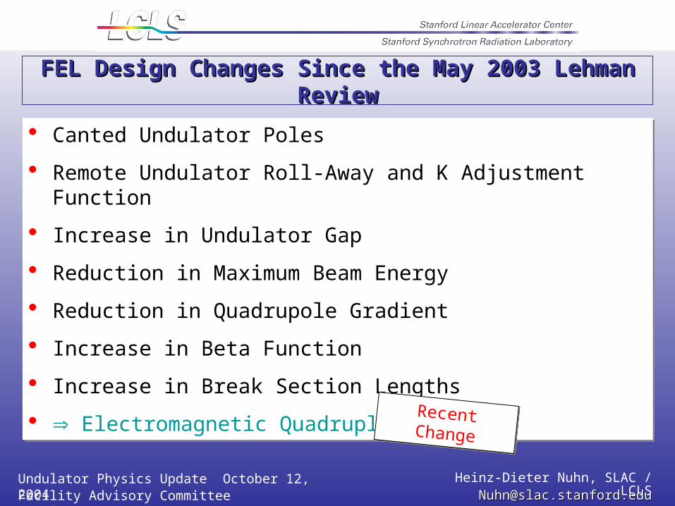
FEL Design Changes Since the May 2003 Lehman ReviewFEL Design Changes Since the May 2003 Lehman Review
Canted Undulator Poles
Remote Undulator Roll-Away and K Adjustment Function
Increase in Undulator Gap
Reduction in Maximum Beam Energy
Reduction in Quadrupole Gradient
Increase in Beta Function
Increase in Break Section Lengths
Electromagnetic Quadruples
Canted Undulator Poles
Remote Undulator Roll-Away and K Adjustment Function
Increase in Undulator Gap
Reduction in Maximum Beam Energy
Reduction in Quadrupole Gradient
Increase in Beta Function
Increase in Break Section Lengths
Electromagnetic QuadruplesRecent ChangeRecent Change
Undulator Physics Update October 12, 2004 Heinz-Dieter Nuhn, SLAC / LCLSFacility Advisory Committee Meeting [email protected]@slac.stanford.edu
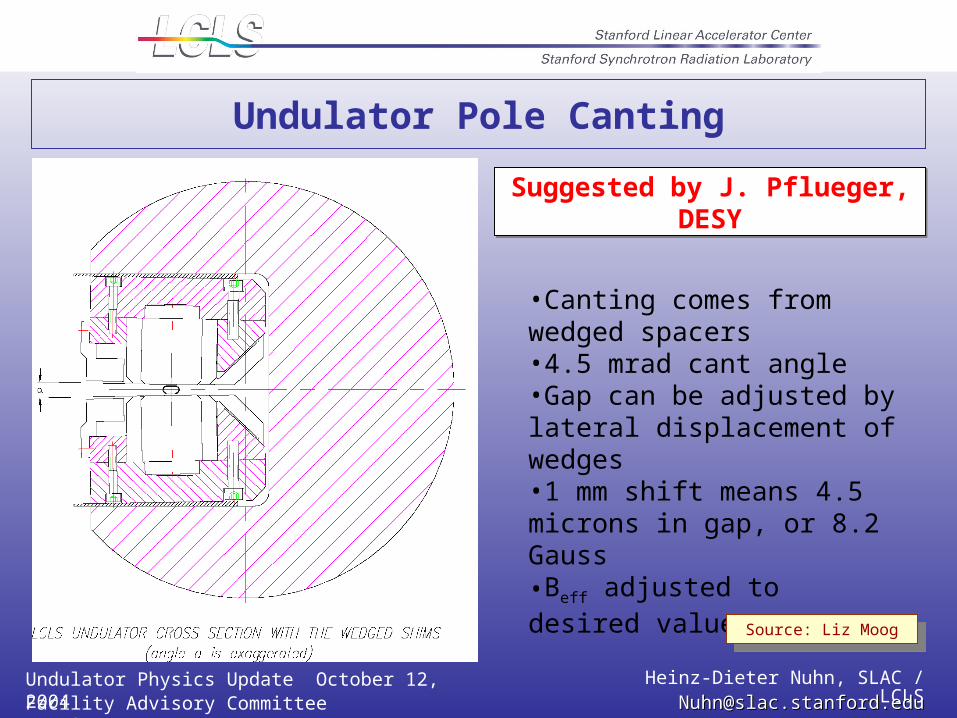
Undulator Pole Canting
•Canting comes from wedged spacers•4.5 mrad cant angle•Gap can be adjusted by lateral displacement of wedges•1 mm shift means 4.5 microns in gap, or 8.2 Gauss •Beff adjusted to desired value
Source: Liz MoogSource: Liz Moog
Suggested by J. Pflueger, DESYSuggested by J. Pflueger, DESY
Undulator Physics Update October 12, 2004 Heinz-Dieter Nuhn, SLAC / LCLSFacility Advisory Committee Meeting [email protected]@slac.stanford.edu
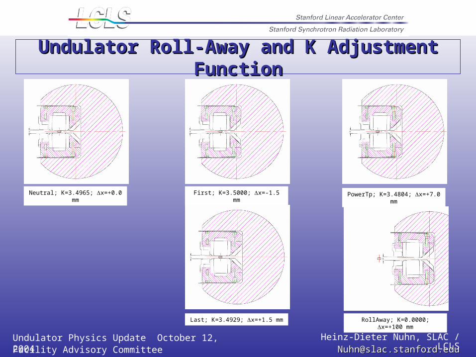
Undulator Roll-Away and K Adjustment FunctionUndulator Roll-Away and K Adjustment Function
Neutral; K=3.4965; x=+0.0 mm First; K=3.5000; x=-1.5 mm
Last; K=3.4929; x=+1.5 mm RollAway; K=0.0000; x=+100 mm
PowerTp; K=3.4804; x=+7.0 mm
Undulator Physics Update October 12, 2004 Heinz-Dieter Nuhn, SLAC / LCLSFacility Advisory Committee Meeting [email protected]@slac.stanford.edu
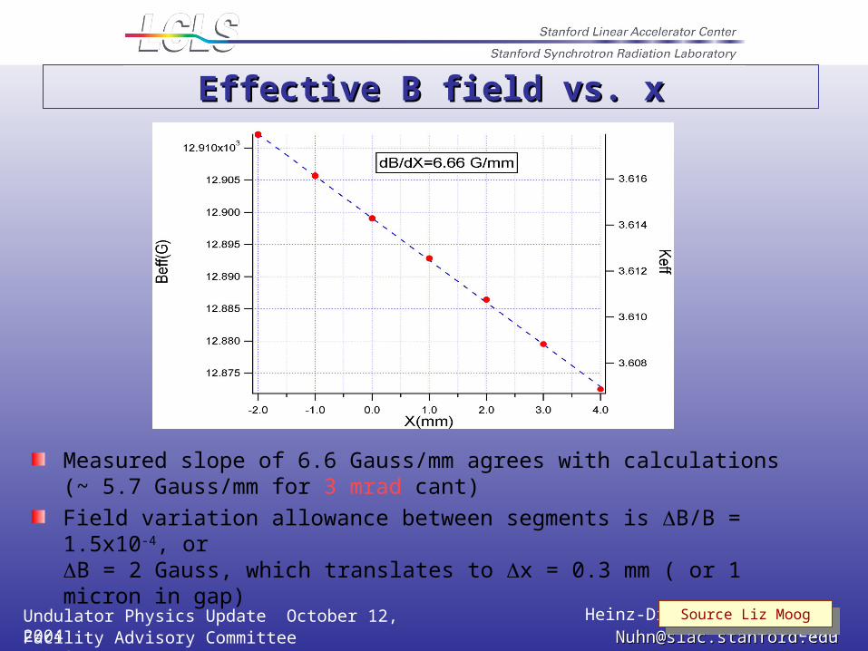
Effective B field vs. xEffective B field vs. x
Measured slope of 6.6 Gauss/mm agrees with calculations(~ 5.7 Gauss/mm for 3 mrad cant)
Field variation allowance between segments is B/B = 1.5x10⁻⁴, or B = 2 Gauss, which translates to x = 0.3 mm ( or 1 micron in gap)
Source Liz MoogSource Liz Moog
Undulator Physics Update October 12, 2004 Heinz-Dieter Nuhn, SLAC / LCLSFacility Advisory Committee Meeting [email protected]@slac.stanford.edu
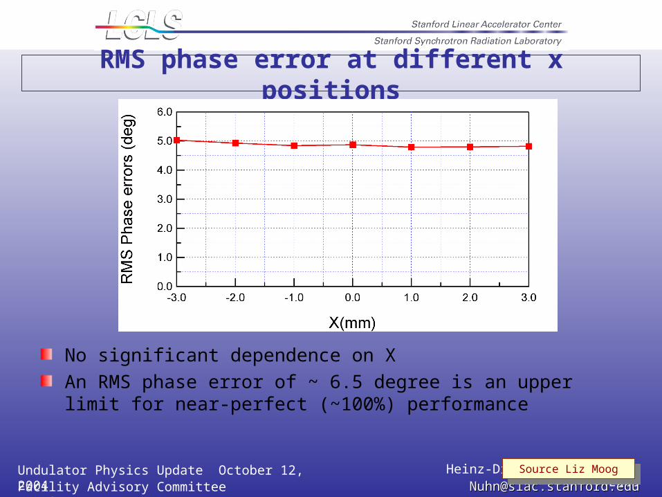
RMS phase error at different x positions
No significant dependence on X
An RMS phase error of ~ 6.5 degree is an upper limit for near-perfect (~100%) performance
Source Liz MoogSource Liz Moog
Undulator Physics Update October 12, 2004 Heinz-Dieter Nuhn, SLAC / LCLSFacility Advisory Committee Meeting [email protected]@slac.stanford.edu
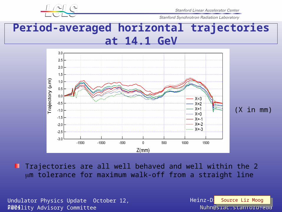
Period-averaged horizontal trajectories at 14.1 GeV
Trajectories are all well behaved and well within the 2 m tolerance for maximum walk-off from a straight line
(X in mm)
Source Liz MoogSource Liz Moog
Undulator Physics Update October 12, 2004 Heinz-Dieter Nuhn, SLAC / LCLSFacility Advisory Committee Meeting [email protected]@slac.stanford.edu
Canting the poles helps in many ways
Facilitates final setting of Beff
Remote control of position allows run-time adjustment
Allows compensating for temperature effect on field strength: ±1.0°C temperature error would require ±1.2 mm lateral shift of undulator
Source Liz MoogSource Liz Moog
Undulator Physics Update October 12, 2004 Heinz-Dieter Nuhn, SLAC / LCLSFacility Advisory Committee Meeting [email protected]@slac.stanford.edu
Change in Undulator Quadrupole Technology
LCLS undulator contains 33 quadrupole magnets located in break sections.
Permanent magnet technology (PMQ) in the past
Now changed to electromagnet technology (EMQ)
Initial cost estimate $740k lower that costs budgeted for permanent magnet solution
Undulator Physics Update October 12, 2004 Heinz-Dieter Nuhn, SLAC / LCLSFacility Advisory Committee Meeting [email protected]@slac.stanford.edu
Some of the reasons for using PMQ in the past
Sufficient for focusing of entire operational range
Sufficient for BBA
Small. Fit into small break sections
No heat dissipation. No cooling water requirements.
No magnet power supplies required. No wiring.
No problems from cooling water vibrations.
Undulator Physics Update October 12, 2004 Heinz-Dieter Nuhn, SLAC / LCLSFacility Advisory Committee Meeting [email protected]@slac.stanford.edu
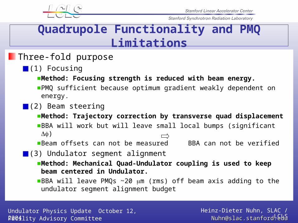
Quadrupole Functionality and PMQ Limitations
Three-fold purpose(1) Focusing
Method: Focusing strength is reduced with beam energy.
PMQ sufficient because optimum gradient weakly dependent on energy.
(2) Beam steeringMethod: Trajectory correction by transverse quad displacement
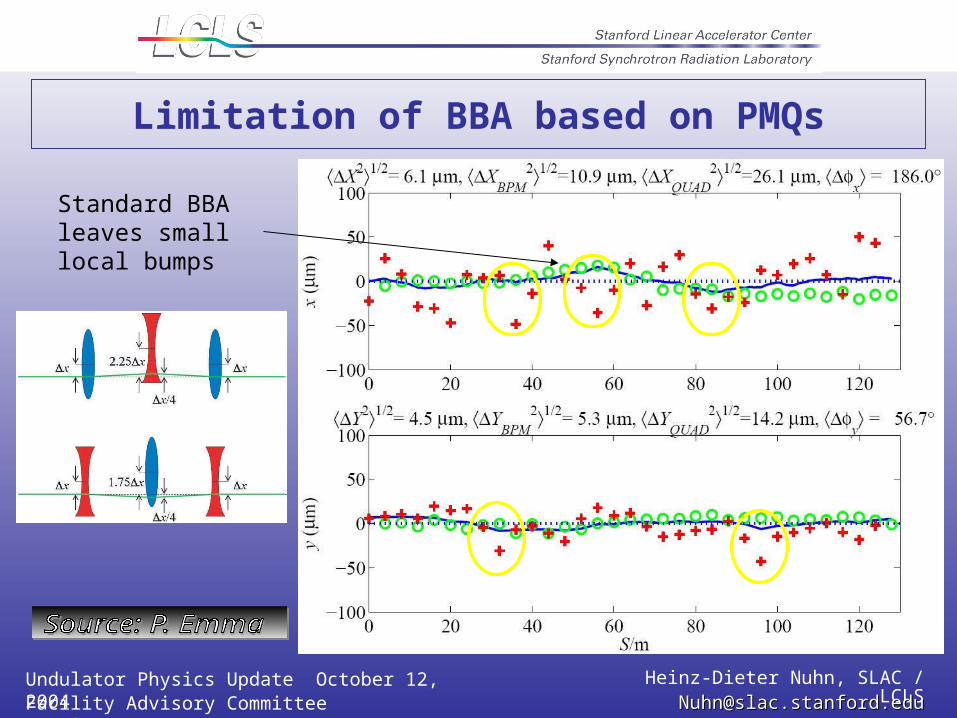
BBA will work but will leave small local bumps (significant )
Beam offsets can not be measured BBA can not be verified
(3) Undulator segment alignmentMethod: Mechanical Quad-Undulator coupling is used to keep beam centered in Undulator.
BBA will leave PMQs ~20 m (rms) off beam axis adding to the undulator segment alignment budget
Undulator Physics Update October 12, 2004 Heinz-Dieter Nuhn, SLAC / LCLSFacility Advisory Committee Meeting [email protected]@slac.stanford.edu
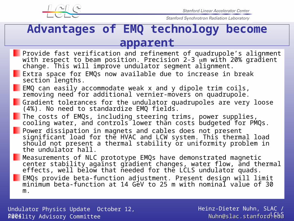
Advantages of EMQ technology become apparent
Provide fast verification and refinement of quadrupole’s alignment with respect to beam position. Precision 2-3 m with 20% gradient change. This will improve undulator segment alignment.Extra space for EMQs now available due to increase in break section lengths.EMQ can easily accommodate weak x and y dipole trim coils, removing need for additional vernier-movers on quadrupole.Gradient tolerances for the undulator quadrupoles are very loose (4%). No need to standardize EMQ fields.The costs of EMQs, including steering trims, power supplies, cooling water, and controls lower than costs budgeted for PMQs.Power dissipation in magnets and cables does not present significant load for the HVAC and LCW system. This thermal load should not present a thermal stability or uniformity problem in the undulator hall.Measurements of NLC prototype EMQs have demonstrated magnetic center stability against gradient changes, water flow, and thermal effects, well below that needed for the LCLS undulator quads.EMQs provide beta-function adjustment. Present design will limit minimum beta-function at 14 GeV to 25 m with nominal value of 30 m.
Undulator Physics Update October 12, 2004 Heinz-Dieter Nuhn, SLAC / LCLSFacility Advisory Committee Meeting [email protected]@slac.stanford.edu
Limitation of BBA based on PMQs
Standard BBA leaves small local bumps
Undulator Physics Update October 12, 2004 Heinz-Dieter Nuhn, SLAC / LCLSFacility Advisory Committee Meeting [email protected]@slac.stanford.edu
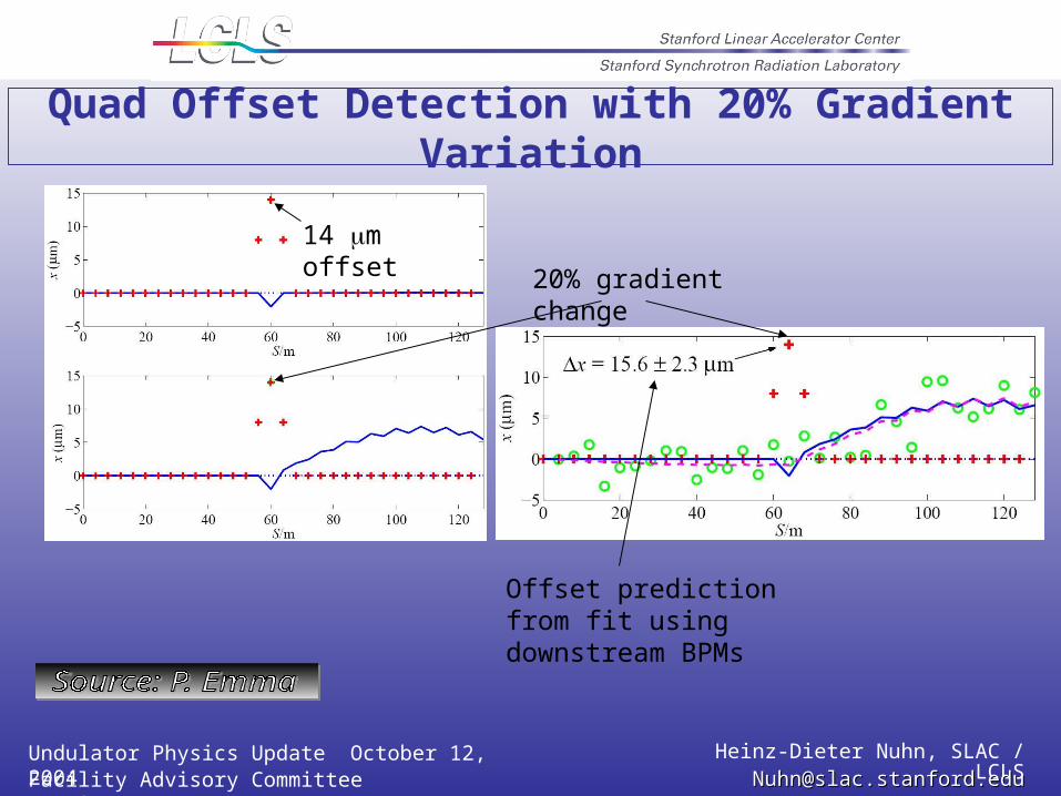
Quad Offset Detection with 20% Gradient Variation
20% gradient change
14 m offset
Offset prediction from fit using downstream BPMs
Undulator Physics Update October 12, 2004 Heinz-Dieter Nuhn, SLAC / LCLSFacility Advisory Committee Meeting [email protected]@slac.stanford.edu
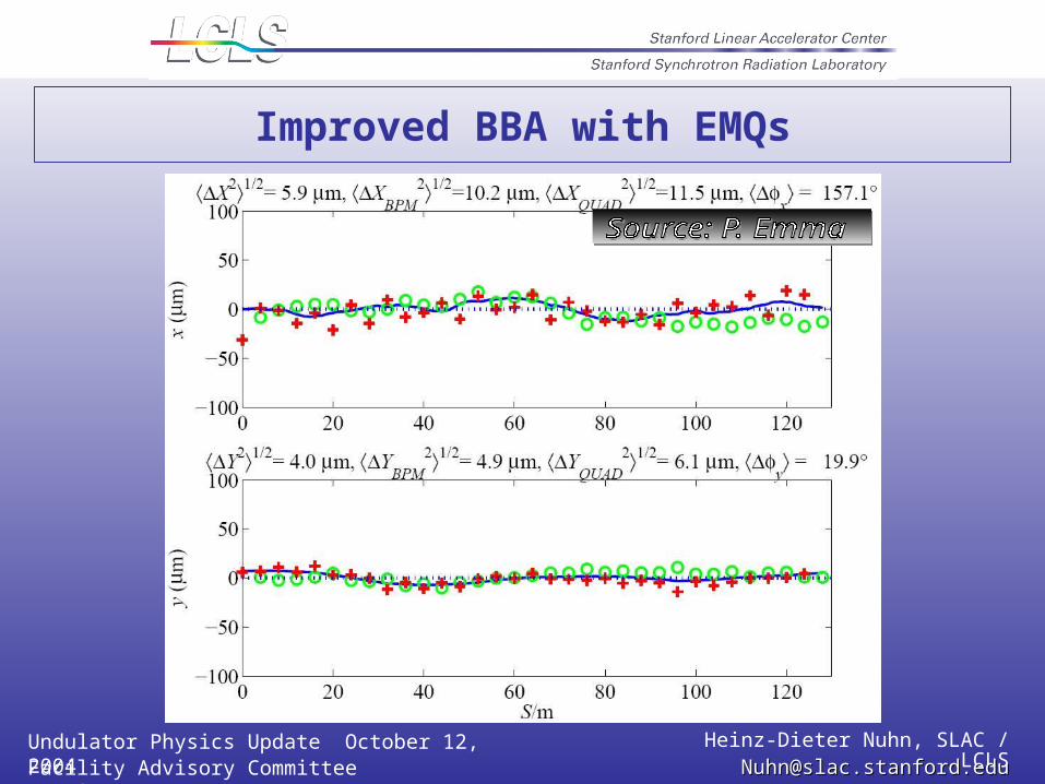
Improved BBA with EMQs
Undulator Physics Update October 12, 2004 Heinz-Dieter Nuhn, SLAC / LCLSFacility Advisory Committee Meeting [email protected]@slac.stanford.edu
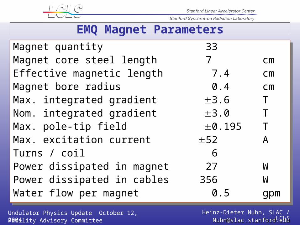
Magnet quantity 33Magnet core steel length 7 cmEffective magnetic length 7.4 cmMagnet bore radius 0.4 cmMax. integrated gradient 3.6 TNom. integrated gradient 3.0 TMax. pole-tip field 0.195 TMax. excitation current 52 ATurns / coil 6Power dissipated in magnet 27 WPower dissipated in cables 356 WWater flow per magnet 0.5 gpm
Magnet quantity 33Magnet core steel length 7 cmEffective magnetic length 7.4 cmMagnet bore radius 0.4 cmMax. integrated gradient 3.6 TNom. integrated gradient 3.0 TMax. pole-tip field 0.195 TMax. excitation current 52 ATurns / coil 6Power dissipated in magnet 27 WPower dissipated in cables 356 WWater flow per magnet 0.5 gpm
EMQ Magnet Parameters
Undulator Physics Update October 12, 2004 Heinz-Dieter Nuhn, SLAC / LCLSFacility Advisory Committee Meeting [email protected]@slac.stanford.edu
Magnet quantity 33
Effective magnetic length 7.4 cm
Maximum dipole field 50 G
Maximum excitation current 2 A
Turns/coil 8
Power dissipated in magnet 0.06 W
Power dissipated in cables 0.12 W
Equivalent EMQ displacement 123 m
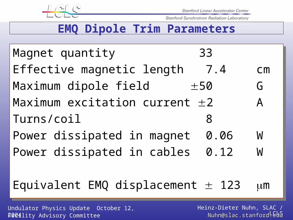
Magnet quantity 33
Effective magnetic length 7.4 cm
Maximum dipole field 50 G
Maximum excitation current 2 A
Turns/coil 8
Power dissipated in magnet 0.06 W
Power dissipated in cables 0.12 W
Equivalent EMQ displacement 123 m
EMQ Dipole Trim Parameters
Undulator Physics Update October 12, 2004 Heinz-Dieter Nuhn, SLAC / LCLSFacility Advisory Committee Meeting [email protected]@slac.stanford.edu
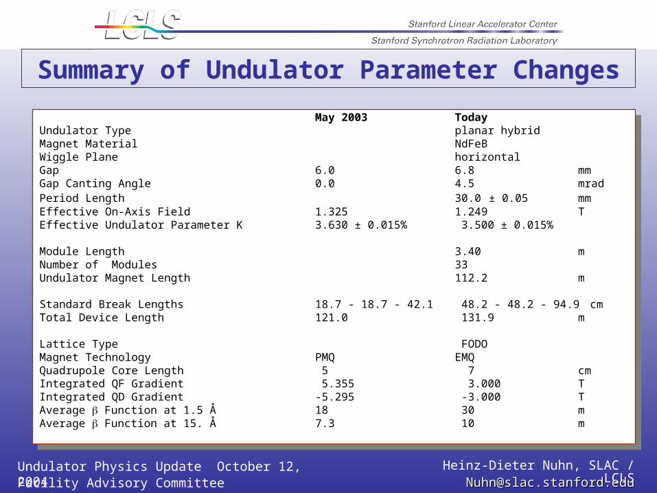
May 2003 TodayUndulator Type planar hybridMagnet Material NdFeBWiggle Plane horizontalGap 6.0 6.8 mmGap Canting Angle 0.0 4.5 mradPeriod Length 30.0 ± 0.05 mmEffective On-Axis Field 1.325 1.249 TEffective Undulator Parameter K 3.630 ± 0.015% 3.500 ± 0.015%
Module Length 3.40 mNumber of Modules 33Undulator Magnet Length 112.2 m
Standard Break Lengths 18.7 - 18.7 - 42.1 48.2 - 48.2 - 94.9 cmTotal Device Length 121.0 131.9 m
Lattice Type FODOMagnet Technology PMQ EMQQuadrupole Core Length 5 7 cmIntegrated QF Gradient 5.355 3.000 TIntegrated QD Gradient -5.295 -3.000 TAverage Function at 1.5 Å 18 30 mAverage Function at 15. Å 7.3 10 m
Summary of Undulator Parameter Changes
Undulator Physics Update October 12, 2004 Heinz-Dieter Nuhn, SLAC / LCLSFacility Advisory Committee Meeting [email protected]@slac.stanford.edu
May 2003 Today Change
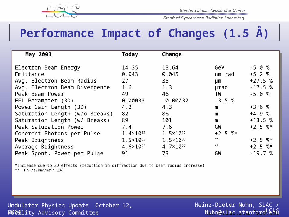
Electron Beam Energy 14.35 13.64 GeV -5.0 %Emittance 0.043 0.045 nm rad +5.2 %Avg. Electron Beam Radius 27 35 µm +27.5 %Avg. Electron Beam Divergence 1.6 1.3 µrad -17.5 %Peak Beam Power 49 46 TW -5.0 %FEL Parameter (3D) 0.00033 0.00032 -3.5 %Power Gain Length (3D) 4.2 4.3 m +3.6 %Saturation Length (w/o Breaks) 82 86 m +4.9 %Saturation Length (w/ Breaks) 89 101 m +13.5 %Peak Saturation Power 7.4 7.6 GW +2.5 %*Coherent Photons per Pulse 1.4×10¹² 1.5×10¹² +2.5 %*Peak Brightness 1.5×1033 1.5×1033 ** +2.5 %*Average Brightness 4.6×10²² 4.7×10²² ** +2.5 %*Peak Spont. Power per Pulse 91 73 GW -19.7 %
*Increase due to 3D effects (reduction in diffraction due to beam radius increase)** [Ph./s/mm2/mr2/.1%]
May 2003 Today Change
Electron Beam Energy 14.35 13.64 GeV -5.0 %Emittance 0.043 0.045 nm rad +5.2 %Avg. Electron Beam Radius 27 35 µm +27.5 %Avg. Electron Beam Divergence 1.6 1.3 µrad -17.5 %Peak Beam Power 49 46 TW -5.0 %FEL Parameter (3D) 0.00033 0.00032 -3.5 %Power Gain Length (3D) 4.2 4.3 m +3.6 %Saturation Length (w/o Breaks) 82 86 m +4.9 %Saturation Length (w/ Breaks) 89 101 m +13.5 %Peak Saturation Power 7.4 7.6 GW +2.5 %*Coherent Photons per Pulse 1.4×10¹² 1.5×10¹² +2.5 %*Peak Brightness 1.5×1033 1.5×1033 ** +2.5 %*Average Brightness 4.6×10²² 4.7×10²² ** +2.5 %*Peak Spont. Power per Pulse 91 73 GW -19.7 %
*Increase due to 3D effects (reduction in diffraction due to beam radius increase)** [Ph./s/mm2/mr2/.1%]
Performance Impact of Changes (1.5 Å)
Undulator Physics Update October 12, 2004 Heinz-Dieter Nuhn, SLAC / LCLSFacility Advisory Committee Meeting [email protected]@slac.stanford.edu
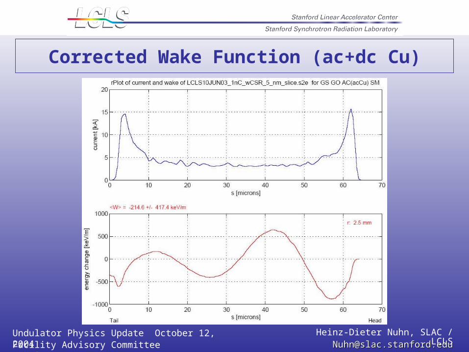
Resistive Wall Wakefield with AC Conductivity
Revised resistive wall wakefield theory by K. Bane and G. Stupakov.
Significant impact on bunch wake function
Study of impact on performance is underway using FEL simulations
Initial results are available.
Revised resistive wall wakefield theory by K. Bane and G. Stupakov.
Significant impact on bunch wake function
Study of impact on performance is underway using FEL simulations
Initial results are available.
Undulator Physics Update October 12, 2004 Heinz-Dieter Nuhn, SLAC / LCLSFacility Advisory Committee Meeting [email protected]@slac.stanford.edu
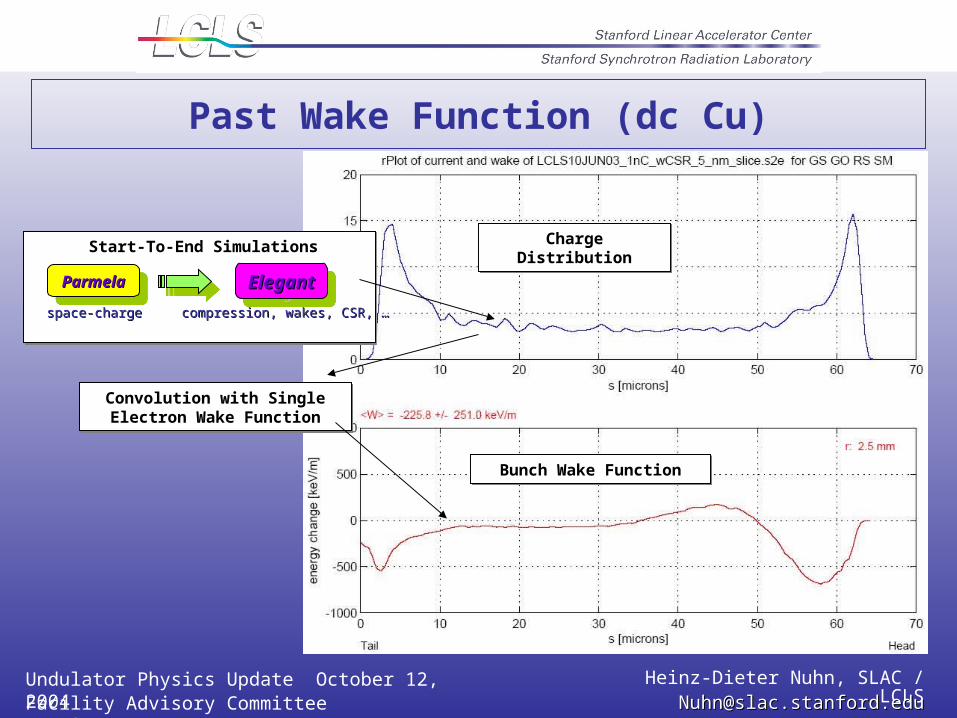
Past Wake Function (dc Cu)
ParmelaParmelaParmelaParmela ElegantElegantElegantElegant
space-chargespace-charge compression, wakes, CSR, …compression, wakes, CSR, …
Start-To-End Simulations
Convolution with Single Electron Wake Function
Convolution with Single Electron Wake Function
Charge DistributionCharge Distribution
Bunch Wake FunctionBunch Wake Function
Undulator Physics Update October 12, 2004 Heinz-Dieter Nuhn, SLAC / LCLSFacility Advisory Committee Meeting [email protected]@slac.stanford.edu
Corrected Wake Function (ac+dc Cu)
Undulator Physics Update October 12, 2004 Heinz-Dieter Nuhn, SLAC / LCLSFacility Advisory Committee Meeting [email protected]@slac.stanford.edu
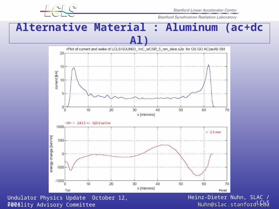
Alternative Material : Aluminum (ac+dc Al)
Undulator Physics Update October 12, 2004 Heinz-Dieter Nuhn, SLAC / LCLSFacility Advisory Committee Meeting [email protected]@slac.stanford.edu
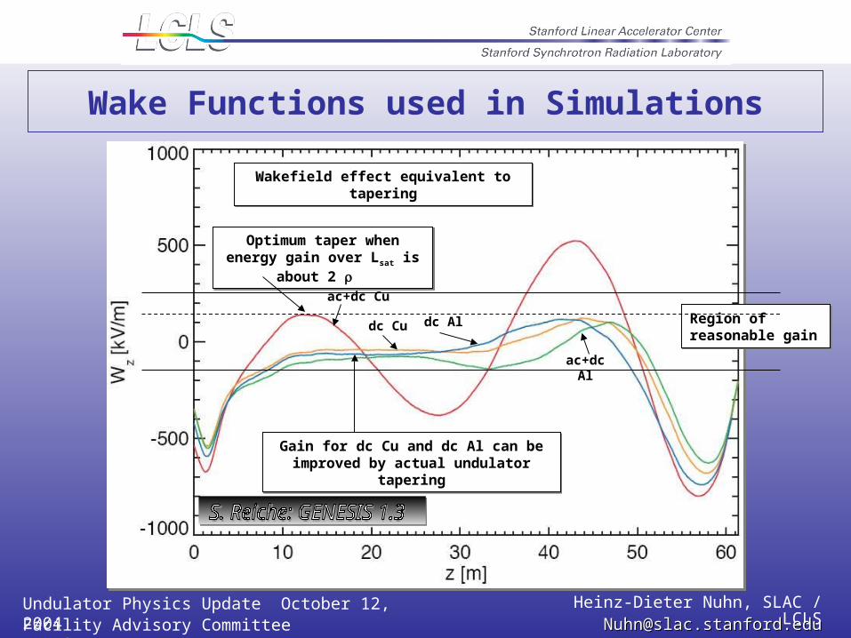
Wake Functions used in Simulations
Wakefield effect equivalent to taperingWakefield effect equivalent to tapering
Region of reasonable gainRegion of reasonable gain
Optimum taper when energy gain over Lsat is about 2
Optimum taper when energy gain over Lsat is about 2
ac+dc Cu
dc Aldc Cu
ac+dc Al
Gain for dc Cu and dc Al can be improved by actual undulator tapering
Gain for dc Cu and dc Al can be improved by actual undulator tapering
Undulator Physics Update October 12, 2004 Heinz-Dieter Nuhn, SLAC / LCLSFacility Advisory Committee Meeting [email protected]@slac.stanford.edu
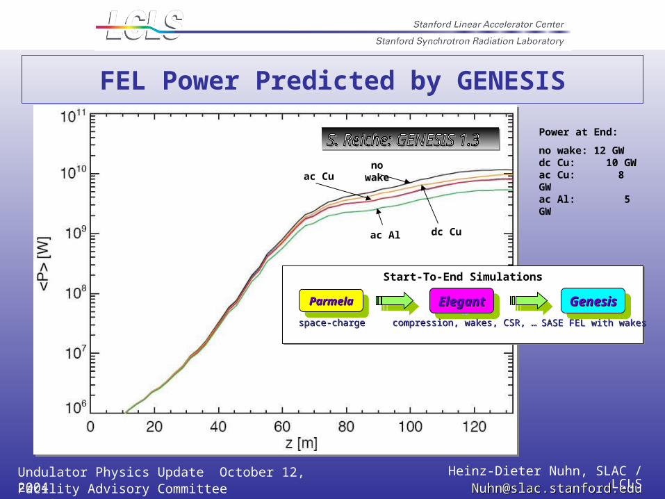
FEL Power Predicted by GENESIS
ParmelaParmelaParmelaParmela ElegantElegantElegantElegant GenesisGenesisGenesisGenesis
space-chargespace-charge compression, wakes, CSR, …compression, wakes, CSR, … SASE FEL with wakesSASE FEL with wakes
Start-To-End Simulations
ac Cuno wake
dc Cuac Al
Power at End:
no wake: 12 GWdc Cu: 10 GWac Cu: 8 GWac Al: 5 GW
Undulator Physics Update October 12, 2004 Heinz-Dieter Nuhn, SLAC / LCLSFacility Advisory Committee Meeting [email protected]@slac.stanford.edu
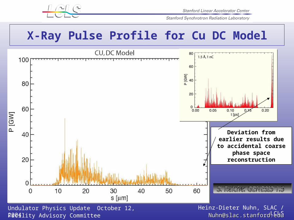
X-Ray Pulse Profile for Cu DC Model
Deviation from earlier results due to accidental
coarse phase space reconstruction
Deviation from earlier results due to accidental
coarse phase space reconstruction
Undulator Physics Update October 12, 2004 Heinz-Dieter Nuhn, SLAC / LCLSFacility Advisory Committee Meeting [email protected]@slac.stanford.edu
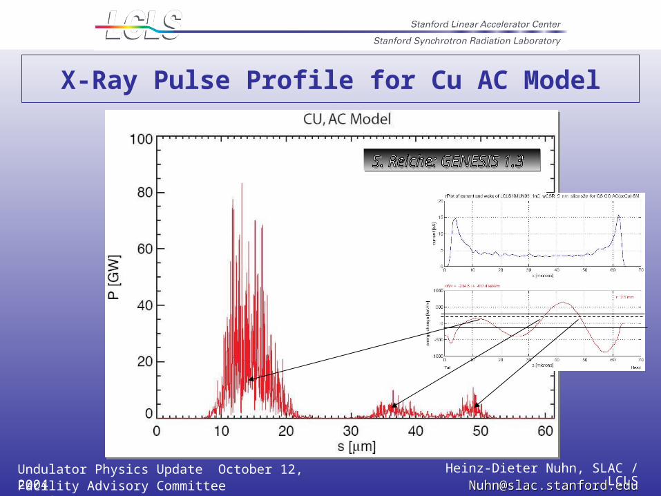
X-Ray Pulse Profile for Cu AC Model
Undulator Physics Update October 12, 2004 Heinz-Dieter Nuhn, SLAC / LCLSFacility Advisory Committee Meeting [email protected]@slac.stanford.edu
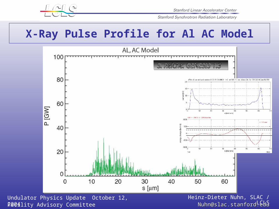
X-Ray Pulse Profile for Al AC Model
Undulator Physics Update October 12, 2004 Heinz-Dieter Nuhn, SLAC / LCLSFacility Advisory Committee Meeting [email protected]@slac.stanford.edu
Alternate Vacuum Chamber Cross Sections
Parallel plates reduce wakefield effect by 30-40%(as shown by K. Bane)
Elliptical or rectangular chamber with ratio 2:1 or larger is reasonable approximation.
This will be investigated with simulations.
Parallel plates reduce wakefield effect by 30-40%(as shown by K. Bane)
Elliptical or rectangular chamber with ratio 2:1 or larger is reasonable approximation.
This will be investigated with simulations.
Undulator Physics Update October 12, 2004 Heinz-Dieter Nuhn, SLAC / LCLSFacility Advisory Committee Meeting [email protected]@slac.stanford.edu
Alternate Vacuum Chamber Radius ?
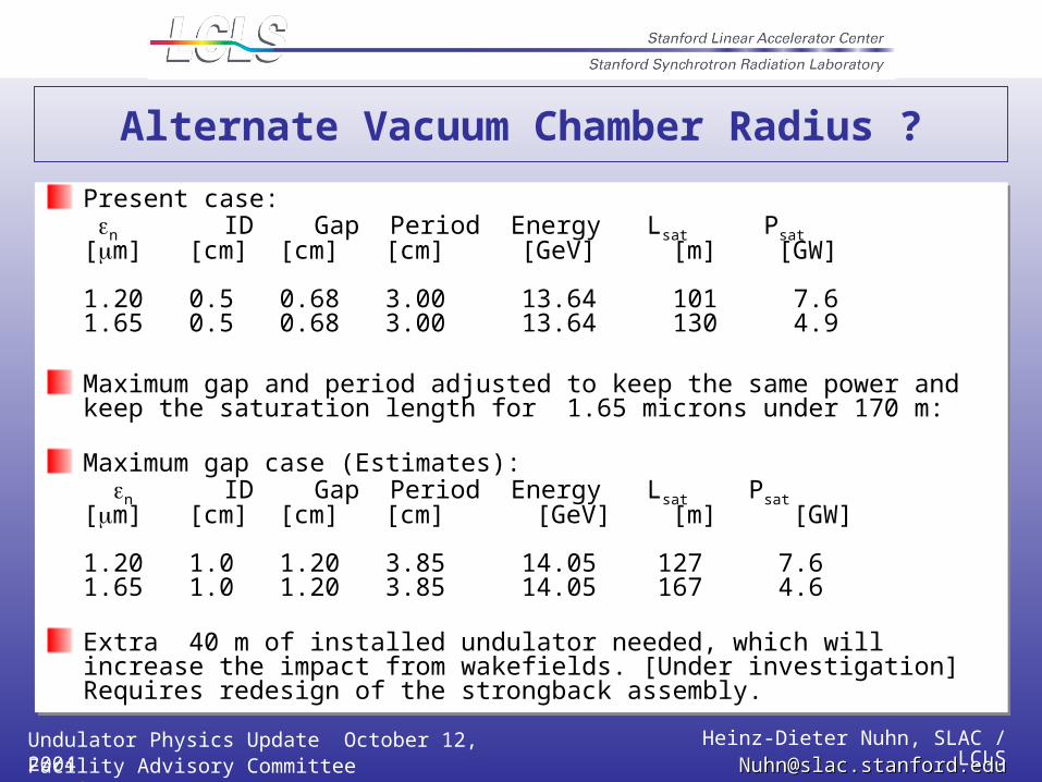
Present case: n ID Gap Period Energy Lsat Psat [m] [cm] [cm] [cm] [GeV] [m] [GW]
1.20 0.5 0.68 3.00 13.64 101 7.6 1.65 0.5 0.68 3.00 13.64 130 4.9
Maximum gap and period adjusted to keep the same power and keep the saturation length for 1.65 microns under 170 m:
Maximum gap case (Estimates): n ID Gap Period Energy Lsat Psat [m] [cm] [cm] [cm] [GeV] [m] [GW]
1.20 1.0 1.20 3.85 14.05 127 7.6 1.65 1.0 1.20 3.85 14.05 167 4.6
Extra 40 m of installed undulator needed, which will increase the impact from wakefields. [Under investigation] Requires redesign of the strongback assembly.
Undulator Physics Update October 12, 2004 Heinz-Dieter Nuhn, SLAC / LCLSFacility Advisory Committee Meeting [email protected]@slac.stanford.edu
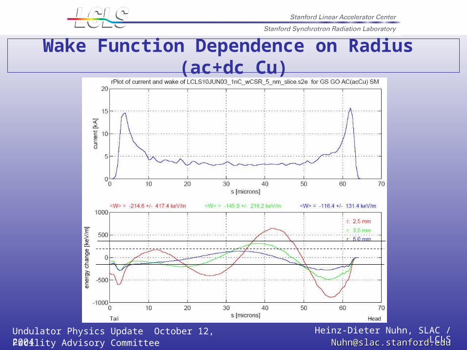
Wake Function Dependence on Radius (ac+dc Cu)
Undulator Physics Update October 12, 2004 Heinz-Dieter Nuhn, SLAC / LCLSFacility Advisory Committee Meeting [email protected]@slac.stanford.edu
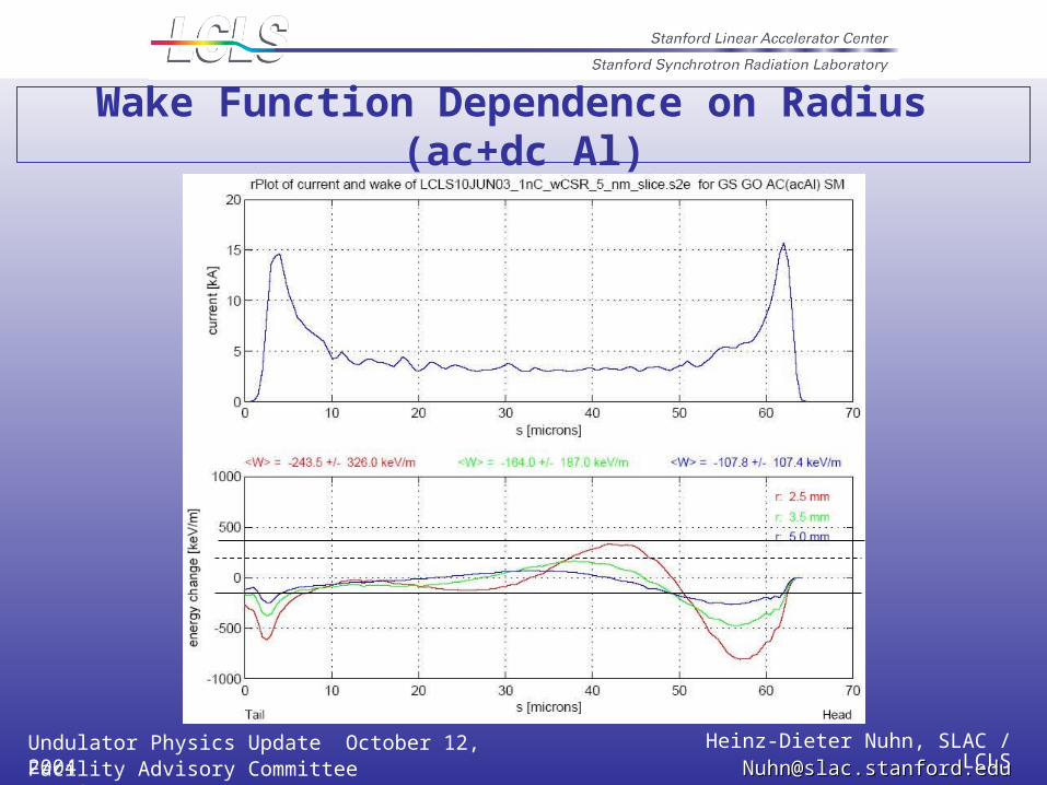
Wake Function Dependence on Radius (ac+dc Al)
Undulator Physics Update October 12, 2004 Heinz-Dieter Nuhn, SLAC / LCLSFacility Advisory Committee Meeting [email protected]@slac.stanford.edu
Conclusions
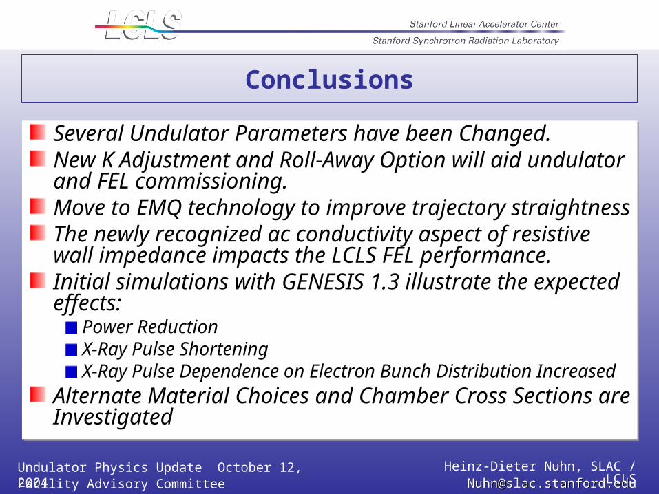
Several Undulator Parameters have been Changed.New K Adjustment and Roll-Away Option will aid undulator and FEL commissioning.Move to EMQ technology to improve trajectory straightnessThe newly recognized ac conductivity aspect of resistive wall impedance impacts the LCLS FEL performance. Initial simulations with GENESIS 1.3 illustrate the expected effects:
Power ReductionX-Ray Pulse ShorteningX-Ray Pulse Dependence on Electron Bunch Distribution Increased
Alternate Material Choices and Chamber Cross Sections are Investigated
Undulator Physics Update October 12, 2004 Heinz-Dieter Nuhn, SLAC / LCLSFacility Advisory Committee Meeting [email protected]@slac.stanford.edu
End of Presentation
Recommended