Global l ine of premium compact
low voltaGe switchGear
UL Low VoLtage Disconnect
switches

2 mersen • Surge-Trap® Solutions
mersen’s l ine of premium low voltaGe switchGear
t h e s a f e s t way to s w i tc h p ow e r o n a n D o f f i n yo U r i n D U s t r i a L c o n t r o L pa n e L s
You need a range of disconnect switches for
your industrial control requirements ranging from
“Service Entrance Rated” to motor isolation. You
need DIN-rail and direct mountable disconnect
switches that conform to UL 508 and UL 98. You
need a range of handles, shafts and accessories to
select from.
Mersen Electrical Power has now the broadest
range of switches in the industry, with a full line
of accessories to accommodate virtually any
application. This range is global and encompasses
both UL and IEC standard products for AC and
DC applications. On the UL side, our fusible line of
switches now extends to 1200A
Class L.
Compact size enables the smallest footprint
amongst the competition. Our 40A UL508 switches
are only 35mm wide! Comfortable pistol-style
handles allow greater leverage and gripping force.
Robust design incorporates rugged, pivot-able
mounting feet.
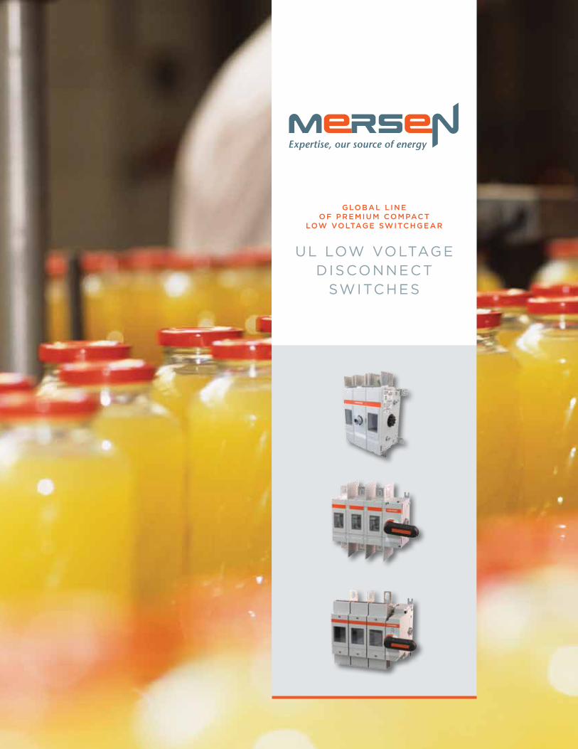
Non-Fusible Switches16A to 1200A, 600VAC
PV-Rated Switches100A to 400A, Up to 1500 VDC
Fusible Switches30A to 1200A, 600VAC
• Performance: Higher
power ratings than
competition, suitable for
many applications
• Size: Typically has the
smallest footprint
• Flexibility in installation: Fast and reliable installation every time
• Environmental impact: All products
conform to RoHS and REACH
• Safety: Safe to install and
safe to the user
• Performance: Suitable for
all locations in low voltage networks
• Size: Typically has the smallest footprint
• Flexibility in installation: Complete range
of accessories which support installation
flexibility
• Environmental impact: All products
conform to RoHS and REACH
• Safety: Touchsafe design with
visible contacts
• Performance: Higher power
ratings than competition,
suitable for many applications
• Size: Typically has the smallest
footprint
• Flexibility in installation: Fast and reliable
installation every time
• Environmental impact: All products
conform to RoHS and REACH

ep.mersen.com • UL Low Voltage Disconnect Switches 3
ul 508 non-fusible disconnect switches (m163 – m803)
The M-series Load Break Switch is the most compact industrial-grade
switch on the market. Capable of making or breaking loads up to
600V (UL), it is suitable as a motor disconnect. Extremely compact
and robust, these switches have a variety of mounting options
including DIN-rail, base, or door-mounting. A wide assortment of
handles, shafts and accessories is available to accommodate any
installation requirement.
F E AT U R E S / B E N E F I T S
• Compact
• Robust
• DIN-rail, base, or door-mounting
• Choice of handles and shafts
• Padlockable
• Side-mount auxiliary contacts and additional poles
• Double-break, silver-plated contacts
a p p L i c at i o n s
• Line of sight disconnect
• Electrical isolation
disconnect switches
UL 508 NON-FUSIBLE
R AT I N g S ( U L ) :
• Volts: 600VAC
• Amps: 20, 30, 40, 63, and 80A.
Suitable as motor disconnect
up to 40hp.
A P P R OVA L S :
• UL 508 listed E196672
• IEC 60947-3
cataloG number desiGnation
MSwitch
M = Mersen AC Switch
80Ampacity
16-80
3Number of Poles
_____Special Configurations
DM: Door Mounting
• Branch-circuit switch
• Motor disconnect

4 ep.mersen.com • UL Low Voltage Disconnect Switches
ul 508 non-fusible disconnect switches (m163 – m803)
ul 508 disconnect switches—front operated
M163 M163DM M633 M633DM
switch body ampere ratinG 20 30 40 63 80
Base Part # M163 M253 M403 M633 M803
Door-Mounted Version M163DM M253DM M403DM M633DM M803DM
handles and shafts direct front operation lockinG handle
HD40 HD40 HD40 HD125 HD125
external front operation
Selector Style NEMA Type 1, 3R, 12 HSBX, HSRX
Shaft—SAxxx (xxx = length in mm) SA85, SA105, SA120, SA130, SA180, SA250
Door mounted version (no shaft required) HSBPDM, HSRPDM HSBWDM, HSRWDM
Pistol Style NEMA Type 1, 3R, 12 HB45, HR45, HB65, HR65, HB80, HR80
NEMA Type 4, 4X HB45X, HR45X, HB65X, HR65X, HB80, HB80X
NEMA 4X Stainless Steel HM65X
Shaft— SAxxx (xxx = length in mm) SPA130, SPA210, SPA290, SPA360, SPA430
B=Black, R=Black
accessories fourth poles
Limited to one additional pole per switch 4P40 4P40 4P40 4P80 4P80
neutral poles
Limited to one additional pole per switch NP40 NP40 NP40 NP80 NP80
terminal shrouds
3-pole TS40-3 TS40-3 TS40-3 TS63-3 TS63-3
4-pole (Add this to the 3-pole shroud) TS40-1 TS40-1 TS40-1 TS63-1 TS63-1
auxiliary contacts*
NC Right side mounting OA1G01 OA1G01 OA1G01 OA1G01 OA1G01
NO left side mounting OA1G10 OA1G10 OA1G10 OA1G10 OA1G10
NO+NC (Mounting on either side) OA2G11 OA2G11 OA2G11 OA2G11 OA2G11
*Rated 2A max continous @690VAC
4P40 4P80
OA1G10
OA1G01
OA2G11
SA105 SPA130
HB65
HD40

ep.mersen.com • UL Low Voltage Disconnect Switches 5
ul 508 non-fusible disconnect switches (m163 – m803)
technical data accordinG to ul/culus
part number m163 m253 m403 m633 m803
General purpose amp ratinG pf= 0.7...0.8 -40° to 40 °C a 20 30 40 60 80
Maximum Operating Voltage V 600 600 600 600 600
Max. horsepower rating / motor FLA current
pf= 0.4...0.5 Three phase
240 V HP/A 5/15.2 7.5/22.0 10/28.0 15/42.0 20/54.0
480 V HP/A 10/14.0 15/21.0 20/27.0 30/40.0 40/52.0
600 V HP/A 11-Oct 20/22.0 25/27.0 30/32.0 40/41.0
Single phase120 V HP/A 1/16.0 1.5/20.0 2/24.0 2/24.0 2/24.0
240 V HP/A 2/13.2 3/18.7 5/30.8 7.5/40.0 10/57.5
Short circuit rating with fuse
Maximum fuse size A 30 602) 30 602) 30 602) 100 150 100 150
Fuse type CC kA 10 10 10
Fuse type J kA 10 10 10 10 10 10 100 100
Fuse type T kA 10 10 10 10 10 10 100 100
Fuse type RK1 kA 10 10 10 10 5 10 5
Fuse type RK5 kA 5 5 5 5 5 5 5 5
Fuse type L kA
Fuse type H kA
enduranCes
Min. electrical endurance, pf. 0.75...0.8 oper. cycles 6 000 6 000 6 000 6 000 6 000
Mechanical endurance operations 20 000 20 000 20 000 20 000 20 000
Terminal lug kits Integral Integral Integral Integral Integral
Wire range AWG 18-8 18-8 18-8 14-4 14-4
Torque Wire tightening lb. in 7 7 7 18 18
Lug mounting
technical data accordinG to iec 60947-3Rated insulation voltage and rated operational voltage AC20/DC20 Pollution degree 3 V 750 750 750 750 750
Dielectric strength 50 Hz 1min. kV 6 6 6 6 6
Rated impulse withstand voltage kV 8 8 8 8 8
Rated operational current, AC-22A
up to 415 V A 16 25 40 63 80
440...500 V A 16 25 40 63 80
690 V A 16 25 40 63 80
Rated operational current, AC-23A
up to 415 V A 16 20 23 45 75
440 V A 16 20 23 45 65
500 V A 16 20 23 45 58
690 V A 10 11 12 20 20Rated conditional short-circuit current Ip (r.m.s.) and corresponding max. allowed cut-off current îc. The cut-off current îc refers to values listed by fuse manufacturers
Ip (r.m.s.) 50 kA kA 6.5 6.5 6.5 13 13
Max. fuse size gG/aM 415 V A 40/32 40/32 40/32 100/80 100/80
Ip (r.m.s.) 10 kA kA
Max. fuse size gG/aM 690 V A
(single phase test acc. to IEC60269)
Ip (r.m.s.) 50 kA kA 4 4 4 11 11
Max. fuse size gG/aM 690 V A 25/16 25/16 25/16 80/63 80/63
at prospective SC-current 80 kA kA
Max. fuse size gG/aM 690 V A
Rated short-time withstand current r.m.s. -value Icw 690 V, 1 s kA 0.5 0.5 0.5 1 1.5
Rated short circuit making capacity Peak value Icm 690 V/500 V A 0.705 0.705 0.705 1.4 2.1
Power loss / pole At rated operational current W 0.3 0.6 1.6 2.8 4.5
Mechanical endurance Divide by two for operation cycles Oper. 20 000 20 000 20 000 20 000 20 000
Weight without accessories 3-pole kg 0.11 0.11 0.11 0.27 0.27
4-pole kg 0.15 0.15 0.15 0.35 0.351) UL Listed switches are also CSA Approved. 2) Fuse size 70A for RK5.

6 ep.mersen.com • UL Low Voltage Disconnect Switches
ul 98 non-fusible disconnect switches
Mersen’s non-fusible disconnect switches are listed to UL 98 and
bear the CE mark as conformance to IEC 60947-3. They are “service
entrance” devices that are capable of fully rated load-break and
load-make. All switches over 100A have windows to provide visual
indication of the contact status. Engineered to have the smallest
footprint, these switches also employ a modular design that enables
the handle to be placed amongst the poles or at the ends.
A wide range of ergonomic handles are available, as are all manner of
accessories, to accommodate multiple applications.
F E AT U R E S / B E N E F I T S
• Service entrance rated
• Front or side operation
• Most compact size
• Internally mounted auxiliary
contacts
• Flange mounting accessories
• 15-year warranty
disconnect switches
UL 98 NON-FUSIBLE
R AT I N g S ( U L ) :
• Volts: 600VAC
• Amps: 30A, 60A, 100A, 200A,
400A, 600A, 800A, 1200A
• Short-Circuit Current Rating (SCCR): Up to 200kA with
fuses. Suitable as motor
disconnect
A P P R OVA L S :
• All UL switches meet the
requirements of UL and CSA
• UL listed guide WHTY, File
E191605 for UL 98 (ratings from
30 A to 1200 A)
• IEC 60947-3
cataloG number desiGnation
MSwitch
M = Mersen AC Switch
200Ampacity
16-1200
UType
U = non-fused UL 98
3Number of Poles/Left of handle
1-3
0Number of
Poles/Right of handle
Blank = < 200A
non-fused, 0, 2, 3
_____Revision
Blank = 0
_____Special
Configuration
F = Flange-mount
ActuationDM = Door mounted
c o n f i g U r at i o n s
Gearbox on the side
Gearbox in the middle
Side operated

ep.mersen.com • UL Low Voltage Disconnect Switches 7
ul 98 non-fusible disconnect switches
ul 98 disconnect switches
M100U3 M200U30 with HD250 Direct Handle M200U30
switch body ampere ratinG 30 60 100 200Base Part # M30U3 M60U3 M100U3 M200U
3-pole configurations 12, 30
For Flange-mount Actuation M30U3F M60U3F M100U3F
For Door-mounting M30U3DM M60U3DM M100U3DM
handles and shafts direct front operation lockinG handleHD125 HD125 HD125 HD250
external front operationSelector Style HSBX, HSRX N/A
Shaft—SAxxx (xxx = length in mm) SA85, SA105, SA120, SA130, SA180, SA250 N/A
Door mounted version (no shaft required) HSBWDM, HSRWDM N/A
Pistol Style NEMA Type 1, 3R, 12 HB45, HR45, HB65, HR65, HB80, HR80
NEMA Type 4, 4X HB45X, HR45X, HB65X, HR65X, HB80X, HR80X
NEMA 4X Stainless Steel HM65X
Shaft— SAxxx (xxx = length in mm) SPA130, SPA210, SPA290, SPA360, SPA430
B=Black, R=Black
accessories fourth poles4P60 4P60 4P125 4P250
neutral polesNP60 NP60 NP125
terminal shrouds3-pole TS125-3 TS125-3 TS125-3 TS250-13
4-pole TS125-1 TS125-1 TS125-1 TS250-14
Shrouds with “-3” suffix are single shrouds that cover all three terminals. Shrouds with “-13” or “-14” are single pole shrouds with 3 or 4 per
auxiliary contacts*Normally Closed OA1G01 OA1G01 OA1G01 OA3G01
Normally Open OA1G10 OA1G10 OA1G10 OA1G10
NO+NC OA2G11 OA2G11 OA2G11
Module for 8 aux. contacts N/A N/A N/A OEA28
*Rated 2A max continous @690VAC
flanGe operation
Flange bracket assemblyIncl with M30U3F**
Incl with M60U3F**
Incl with M100U3F** FOM4
Rod Flange handle NEMA 12 FHR12 FHR12 FHR12 NA
Rod Flange handle NEMA 4X FHR4X FHR4X FHR4X NA
Rod, 16 inch RODNF16 RODNF16 RODNF16 NA
Rod, 24 inch RODNF24 RODNF24 RODNF24 NA
Cable Flange Handle, NEMA 12 NA NA NA FHC12
Cable Flange Handle, NEMA 4X NA NA NA FHC4X
Cable for FHC handles NA NA NA CABLE36*
Other cable lengths available: 48”, 60”, 72”, 84”, 96”, 108”. For example, CABLE108. **These switches have not been tested to conform to UL standards
4P125 4P250
TS250-13
OA1G10
OA1G01
OA2G11
OEA28
HSBX
HB65
HD250
8 ep.mersen.com • UL Low Voltage Disconnect Switches
ul 98 non-fusible disconnect switches
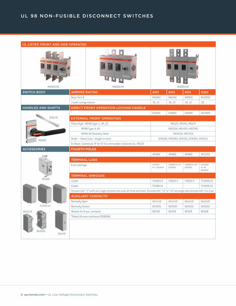
ul listed front and side operated
M400U30 M600U30 M200U30
switch body ampere ratinG 400 600 800 1200
Base Part # M400U M600U M800U M1200U
3-pole configurations 30, 12 30, 12 30, 12 30
handles and shafts direct front operation lockinG handle
HD400 HD800 HD800 HD1000
external front operation
Pistol Style NEMA Type 1, 3R, 12 HB125, HB145, HB274
NEMA Type 4, 4X HB125X, HB145X, HB274X
NEMA 4X Stainless Steel HM125X, HM175X
Shaft— SAxxx (xxx = length in mm) SFB185, SFB280, SFB325, SFB395, SFB535
B=Black. Substitute ‘R’ for ‘B’ if a red handle is desired. Ex. HR125
accessories fourth poles
4P400 4P800 4P800 4P1250
terminal luGs
6 per package LUG400 #2 - 600MCM
LUG800 2 x #2 600MCM
LUG800 2 x #2 600MCM
LUG1200 4 x #2 600MCM
terminal shrouds
3-pole TS400-13 TS600-3 TS800-3 TS1600-13
4-pole TS400-14 TS1600-14
Shrouds with “-3” suffix are single shrouds that cover all three terminals. Shrouds with “-13” or “-14” are single pole shrouds with 3 or 4 per
auxiliary contacts*
Normally Open OA1G10 OA1G10 OA1G10 OA1G10
Normally Closed OA3G01 OA3G01 OA3G01 OA3G01
Module for 8 aux. contacts OEA28 OEA28 OEA28 OEA28
*Rated 2A max continous @690VAC
HD800
SFB135
4P400
TS250-13
OA1G10
OA3G01OEA28

ep.mersen.com • UL Low Voltage Disconnect Switches 9
ul 98 non-fusible disconnect switches
technical data accordinG to ul/culuspart number m30u3 m60u3 m100u3 m200uxx
General purpose amp ratinG pf= 0.7...0.8 -40° to 40 °C a 30 60 100 200Maximum Operating Voltage V 600 600 600 600
Max. horsepower rating / motor FLA current
pf= 0.4...0.5 Three phase
240 V HP/A 10/28.0 20/54.0 30/80.0 75/192.0480 V HP/A 20/27.0 40/52.0 50/65.0 150/180.0600 V HP/A 30/32.0 40/41.0 50/52.0 200/192.0
Single phase 120 V HP/A 2/24.0 3/34.0 5/56.0240 V HP/A 5/28.0 7.5/40.0 15/68.0
Short circuit rating with fuse Maximum fuse size A 60 150 150 200 400Fuse type CC kA Fuse type J kA 50 50 50 200 65Fuse type T kA 50 50 50Fuse type RK1 kAFuse type RK5 kAFuse type L kAFuse type H kA
Maximum General Use, DC ratings
Current rating at 250 VDC A 200at 600 VDC A 100
DC horsepower rating for 4-pole switch at 600 VDC HP 50DC horsepower rating for 2-pole switch In open air at 125 VDC HP 20
In enclosure2) at 250 VDC HP -DC short circuit rating for 4-pole switch with circuit breaker kA 10
DC short circuit rating for 2-pole switch
with circuit breaker at 250 VDC kA 14with circuit breaker at 600 VDC kA 10with class J fuse at 250 VDC kA 100... with fuse size A 200
enduranCesMin. electrical endurance, pf. 0.75...0.8 oper. cycles 6 000 6 000 6 000 6 000Mechanical endurance operations 20 000 20 000 20 000 20 000Terminal lug kits Integral Integral Integral LUG-200Wire range AWG 14-4 14-4 8-1/0 4-300MCMTorque Wire tightening lb. in 55 55 55 275
Lug mounting 72
technical data accordinG to iec 60947-3Rated insulation voltage and rated operational voltage AC20/DC20 Pollution degree 3 V 750 750 750 1 000Dielectric strength 50 Hz 1min. kV 6 6 6 10Rated impulse withstand voltage kV 8 8 8 12
Rated operational current, AC-22A up to 415 V A 40 63 100 250440...500 V A 40 63 100 250690 V A 40 63 100 250
Rated operational current, AC-23A up to 415 V A 40 63 80 250440 V A 40 63 65 250500 V A 40 63 60 250690 V A 40 63 40 250
Rated conditional short-circuit current Ip (r.m.s.) and corresponding max. allowed cut-off current îc. The cut-off current îc refers to values listed by fuse manufacturers
Ip (r.m.s.) 50 kA kA 16.5 16.5 16.5Max. fuse size gG/aM 415 V A 125/125 125/125 125/125Ip (r.m.s.) 10 kA kA 8.2 8.2 8.2Max. fuse size gG/aM 690 V A 125/100 125/100 125/100
(single phase test acc. to IEC60269)
Ip (r.m.s.) 50 kA kA 10 10 10 35Max. fuse size gG/aM 690 V A 63/63 63/63 63/63 355/315at prospective SC-current 80 kA kA 40.5Max. fuse size gG/aM 690 V A 355/315
Rated short-time withstand current r.m.s. -value Icw 690 V, 1 s kA 2.5 2.5 2.5 8Rated short circuit making capacity Peak value Icm 690 V/500 V A 3.6 3.6 3.6 30Power loss / pole At rated operational current W 0.7 1.6 4.0 6.5Mechanical endurance Divide by two for operation cycles Oper. 20 000 20 000 20 000 20 000Weight without accessories 3-pole kg 0.36 0.36 0.36 1.2
4-pole kg 0.50 0.50 0.50 1.51) UL Listed switches are also CSA Approved. 2) Fuse size 70A for RK5.

10 ep.mersen.com • UL Low Voltage Disconnect Switches
ul 98 non-fusible disconnect switches
technical data accordinG to ul/culuspart number m400u m600u m800u m1200u
General purpose amp ratinG pf= 0.7...0.8 -40° to 40 °C a 400 600 800 1200Maximum Operating Voltage V 600 600 600 600
Max. horsepower rating / motor FLA current
pf= 0.4...0.5 Three phase
240 V HP/A 125/312.0 200/480.0 200/602 200/602480 V HP/A 250/302.0 450/515.0 500/590 500/590600 V HP/A 350/338.0 500/472.0 500/472 500/472
Single phase120 V HP/A 240 V HP/A
Short circuit rating with fuse
Maximum fuse size A 600 600 800 800 1200Fuse type CC kA Fuse type J kA 100 100Fuse type T kA 100Fuse type RK1 kAFuse type RK5 kA 100 100 100Fuse type L kAFuse type H kA
Maximum General Use, DC ratings
Current ratingat 250 VDC A 400 600at 600 VDC A 200 200
DC horsepower rating for 4-pole switch at 600 VDC HP 50 -
DC horsepower rating for 2-pole switchIn open air at 125 VDC HP 40 -In enclosure2) at 250 VDC HP 50 50
DC short circuit rating for 4-pole switch with circuit breaker kA 10 10
DC short circuit rating for 2-pole switch
with circuit breaker at 250 VDC kA 14 18with circuit breaker at 600 VDC kA 10 10with class J fuse at 250 VDC kA 100 100... with fuse size A 400 500
enduranCesMin. electrical endurance, pf. 0.75...0.8 oper. cycles 1 000 1 000 500 500Mechanical endurance operations 16 000 10 000 6000 6000Terminal lug kits LUG400 LUG800 LUG800 LUG1200Wire range AWG 2 - 600MCM 2 x 2 - 600MCM 2 x 2 - 600MCM 4 x 2 - 600MCM
Torque Wire tightening lb. in 375 55 500 500Lug mounting 240 480 480 450-670
technical data accordinG to iec 60947-3Rated insulation voltage and rated operational voltage AC20/DC20 Pollution degree 3 V 1 000 1 000 1 000 1 000Dielectric strength 50 Hz 1min. kV 10 10 10 10Rated impulse withstand voltage kV 12 12 12 12
Rated operational current, AC-22Aup to 415 V A 400 800 1600 1600440...500 V A 400 800 1600 1600690 V A 400 800 1600 1600
Rated operational current, AC-23A
up to 415 V A 400 800 1250 1250440 V A 400 800 1250 1250500 V A 400 800 1250 1250690 V A 400 800 1250 1250
Rated conditional short-circuit current Ip (r.m.s.) and corresponding max. allowed cut-off current îc. The cut-off current îc refers to values listed by fuse manufacturers
Ip (r.m.s.) 50 kA kAMax. fuse size gG/aM 415 V AIp (r.m.s.) 50 kA kAMax. fuse size gG/aM 690 V A
(single phase test acc. to IEC60269)
Ip (r.m.s.) 50 kA kA 50.5 71.5Max. fuse size gG/aM 690 V A 500/500 800/1 000at prospective SC-current 80 kA kA 59 83.5Max. fuse size gG/aM 690 V A 500/500 800/1 000
Rated short-time withstand current r.m.s. -value Icw 690 V, 1 s kA 15 20 50 50Rated short circuit making capacity Peak value Icm 690 V/500 V A 65 80 110 110Power loss / pole At rated operational current W 10 40 29 48Mechanical endurance Divide by two for operation cycles Oper. 26 000 10 000Weight without accessories 3-pole kg 2.2 5.2 15.2 15.2
4-pole kg 2.8 6.41) UL Listed switches are also CSA Approved. 2) Fuse size 70A for RK5.

ep.mersen.com • UL Low Voltage Disconnect Switches 11
ul 98 fusible disconnect switches
Mersen’s fusible disconnect switches are listed to UL 98 and bear the
CE mark as conformance to IEC 60947-3. They are “service entrance”
devices capable of fully rated load-break and load-make. While long-
term safety, reliability, and functionality are always paramount in the
design of our products, these switches are also engineered to have the
smallest footprint. The modular design allows placement of the handle
anywhere amongst the poles. The fuse doors cannot open when the
switch is in the “ON” position, and all switches are double-break,
which isolates both fuse clips from voltage during fuse replacement.
The switches’ “Test” position allows actuation of the auxiliary contacts
without main power. Power taps enable energizing a CPT or surge
device without the need for a separate terminal block. A wide range of
ergonomic handles are available, as are all manner of accessories.
F E AT U R E S / B E N E F I T S
• Multiple Configurations
• Power taps
• Adjustable shaft depth
• Fuse monitoring
• Interlocked fuse doors
disconnect switches
UL 98 FUSIBLE
R AT I N g S U L :
• Volts: 600VAC
• Amps: 30, 60, 100, 200, 400,
600, 800, and 1200A
• Short-Circuit Current Rating (SCCR): Up to 200kA with
Class CC, J, or L Fuses
A P P R OVA L S :
• All UL Fusible Disconnect
Switch switches meet UL & CSA
requirements
• UL listed guide WHTY, File
E191605 for UL 98 (ratings from
30A to 1200A)
• IEC 60947-3
cataloG number desiGnation
MSwitch
M = Mersen AC Switch
60Ampacity
30-1200
JType
CC = CC fused
J = J fusedL = L fused
3Number of Poles/Left of handle
1, 2, 3, 4, etc. (N = Neutral)
0Number of
Poles/Right of handle
Blank = < 200A non-
fused, 0, 2
_____Revision
Blank = 0
SSpecial
Configuration
S = side-operated
N = Non-fused switched Neutral
F = Rod-Flange Actuated
c o n f i g U r at i o n s
Gearbox on the side
Gearbox in the middle
Side operated

12 ep.mersen.com • UL Low Voltage Disconnect Switches
ul listed front and side operated
M30CC1230A, CC fused, 3-pole with pole on left side
of handle and 2 poles on right sideM60J30
60A, J fused, with 3 poles on left side of handleM200J30 with HDF200
200A, J fused, 3 poles on left side of direct handle
switch body ampere ratinG 30 60 100 200Base Part # M30 M60 M100 M200Fuse Type CC, J J J J
3- and 4-pole configurations 12, 22, 30F, 30S
12, 22, 22N, 30, 30F, 30S, 40, 40N
12, 22, 22N, 30, 30F, 30S, 40, 40N
30, 40
S = Side operated F = Rod-Flange actuated (Direct Side Operated Handles are included with ‘S’ option)
handles and shafts direct front operationHDF30 HDF200 HDF200 HDF200
external front operation - pistol styleNEMA Type 1, 3R, 12, IP65 HB45 HB65, HB80NEMA Type 4, 4X HB45X HB65X, HB80XNEMA 4X Stainless Steel HM65XB=Black. Substitute ‘R’ for ‘B’ if a red handle is desired. Ex. HR45
shaftsShaft— SPAxxx (xxx = length in mm) SPA130, SPA210, SPA290, SPA360, SPA430
accessories terminal luGs
6 per package Integral Integral LUG100 (#14 - 2/0)
LUG200 (#6 -300MCM)
terminal shrouds3-pole (3 single shrouds per package) Integral Integral TSF160-13 TSF200-134-pole (4 single shrouds per package) T TSF160-14 TSF200-14Shrouds with “-3” suffix are single shrouds that cover all three terminals. Shrouds with “-13” or “-14” are single pole shrouds with 3 or 4 per
auxiliary contacts*NO OA1G10, w/OSZ4 OA1G10 OA1G10 OA1G10NC OA3G01, w/OSZ4 OA3G01 OA3G01 OA3G01NO, between poles OA4B1C N/A N/A N/AMounting plate OA1G10/OA3G01 OSZ4 Not needed Not needed Not neededModule for 8 aux. contacts OEA28 OEA28 OEA28 OEA28*Rated 2A max continous @690VAC
flanGe operation for cable actuation Cable Flange Handle, NEMA 12 FHC12 FHC12 FHC12 FHC12Cable Flange Handle, NEMA 4X FHC4X FHC4X FHC4X FHC4X
Bracket Assembly FOM2FOM3 for M60J12, FOM4 for M60J30
FOM4 FOM4
Cable for FHC handles CABLE36* CABLE36* CABLE36* CABLE36**Other cable lengths available: 48", 60", 72", 84", 96", 108". For example, CABLE108.
flanGe operation for rod actuation*Flange bracket assembly Incl with
M30x30FIncl with M60J30F
Incl with M100J30F
NA
Rod Flange handle NEMA 12 FHR12 FHR12 FHR12 NARod Flange handle NEMA 4X FHR4X FHR4X FHR4X NARod, 16, 21, 26 inch (ex. ROD16) RODxx RODxx RODxx NA*These products have not been tested for UL Compliance
ul 98 fusible disconnect switches
OA3G01OA1G10
OEA28
FOM4, FHC12, and CABLE36 with M200J30
HDF200HR45
HB65

ep.mersen.com • UL Low Voltage Disconnect Switches 13
ul listed front and side operated
M400J30400A, J fused, 3-pole with 3 poles on left side of handle
M800L30800A, L fused, with 3 poles on left side of handle
switch body ampere ratinG 400 600 800 1200
Base Part # M400U M600U M800U M1200U
Fuse Type J J L L
3- and 4-pole configurations 12, 30, 40 12, 30, 40 12, 30, 40 30, 40
handles and shafts direct front operation
HDF400 HDF800T HDF800T HD1250T
external front operation
NEMA Type 1, 3R, 12 HB125, HB145, HB274
NEMA Type 4, 4X HB125X, HB145X, HB274X
NEMA 4X Stainless Steel HM125X, HM175X
B=Black. Substitute ‘R’ for ‘B’ if a red handle is desired. Ex. HR125
shafts
Shaft— SFBxxx (xxx = length in mm) SFB185, SFB280, SFB325, SFB395, SFB535
accessories terminal luGs
6 per package LUG400 #2 - 600MCM
LUG800 2 x #2 600MCM
LUG800 2 x #2 600MCM
LUG1200 4 x #2 600MCM
terminal shrouds
3-pole TSF400-13 TSF600-3 TSF600-3 TSF1250-13
Suffix “-3” indicates a single 3-pole shroud; Suffix “-13” indicates 3 single pole shrouds per package
auxiliary contacts*
Normally Open OA1G10 OA1G10 OA1G10 OA1G10
Normally Closed OA3G01 OA3G01 OA3G01 OA3G01
Module for 8 aux. contacts OEA28 OEA28 OEA28 OEA28
*Rated 2A max continous @690VAC
ul 98 fusible disconnect switches
OA1G01OA1G10
OEA28
TSF400-13
HB125
HDF400SFB135

14 ep.mersen.com • UL Low Voltage Disconnect Switches
ul 98 fusible disconnect switches
technical data accordinG to ul/culus
General purpose amp ratinG pf= 0.7...0.8 -40° to 40 °C a 30 60 100 200
Maximum Operating Voltage VAC 600 600 600 600
VDC 250 250 250 250
Max. horsepower rating / motor FLA current pf= 0.4...0.5 Three phase
240 V HP/A 7.5/22.0 15/42.0 30/80.0 60/154.0
480 V HP/A 15/21.0 30/40.0 60/77.0 125/156.0
600 V HP/A 20/22.0 50/52.0 75/77.0 150/144.0
Single phase 120 V HP/A 2/24.0
240 V HP/A 3/17.0
Short circuit rating with fuse, 3- and 4- pole types kA 200 200 200 200
UL/CSA fuse size A 30 60 100 200
UL/CSA fuse type J/CC J J J
enduranCes
Min. electrical endurance, pf. 0.75...0.8 oper. cycles 6000 6000 6000 6000
Mechanical endurance operations 20 000 20 000 20 000 16 000
Terminal lug kits Integral Integral LUG100 LUG200
Wire range AWG #18-8 #14-4 #14-2/0 #4-300MCM
Torque Wire tightening lb. in 17 30/355) 120 275
Lug mounting lb. in N/A N/A 50 72
technical data accordinG to iec 60947-3
Rated insulation voltage Pollution degree 3 V 1 000 1 000 1 000 1 000
Dielectric strength 50 Hz 1min. kV 10 10 10 10
Rated impulse withstand voltage kV 12 12
Rated thermal current in ambient 40 °C / In open air A/W 32/3.5 63/7.5 160/12 200/17
max. fuse power dissipation1) In enclosure2) A/W 32/3.5 63/7.5 160/10, 135/12
200/15
...with minimum cable cross section Cu mm2 6 16 70 95
Rated operational current, AC-23A up to 500 V A 32 63 160 200
690 V A 32 63 160 200
Rated operational current, AC-233) The kW-ratings are accurate for three-phase 1500 R.P.M. standard asynchronous motors.
230 V kW 7.5 18.5 45 60
400 V kW 15 30 75 110
415 V kW 15 30 75 110
500 V kW 18.5 37 90 132
690 V kW 22 55 132 200
Rated breaking capacity in category AC-23 up to 500 V A 256 504 1280 1600
690 V A 256 504 1280 1600
Rated short-time withstand current, 1 s r.m.s. -value 690 V, 1 s kA 1 2.5 5 8
Power loss / pole With rated current, without fuse W 2 4 9 8
Weight without accessories 3-pole switch fuses kg 0.7 1.3 1.5 2.6
4-pole switch fuses kg 0.9 1.6 1.8
Built-in terminal size Cu mm2 0.75...10 2.5...25
Terminal bolt size (included) Metric thread diameter x length mm M6x20 M8x25
Fuse-links bolts tightening torque Nm 4 4
*) = Utilization category B 1) Ambient temperature 60°C: derating 20% 2) Mounting on “ceiling”: derating 10%. Mounting on wall, horizontal fuses: derating 8%.
3) Some fuses limit these figures further. Starting current characteristics must be considered separately. 4) Approval pending
5) 30 lb.in with cable size #14-10, 35 lb.in with cable size #8-4

ep.mersen.com • UL Low Voltage Disconnect Switches 15
ul 98 fusible disconnect switches
technical data accordinG to ul/culus
General purpose amp ratinG pf= 0.7...0.8 -40° to 40 °C a 400 600 800 1200
Maximum Operating Voltage VAC 600 600 600 600
VDC 250 250 250 250
Max. horsepower rating / motor FLA current pf= 0.4...0.5 Three phase
240 V HP/A 125.0/312.0 200/480.0 250/602.0 250/602.0
480 V HP/A 250.0/302.0 400/477.0 500/590.0 500/590.0
600 V HP/A 350.0/336.0 500/472.0 500/472.0 500/472.0
Single phase 120 V HP/A
240 V HP/A
Short circuit rating with fuse, 3- and 4- pole types kA 200 200 200 200
UL/CSA fuse size A 400 600 800 1200
UL/CSA fuse type J J L L
enduranCes
Min. electrical endurance, pf. 0.75...0.8 oper. cycles 1 000 1 000 500 500
Mechanical endurance operations 12 000 4 000 3 000 2 000
Terminal lug kits LUG400 LUG800 LUG800 LUG1200
Wire range AWG #2-600MCM
(2)#2-600MCM
(2)#2-600MCM
(4)#2-600MCM
Torque Wire tightening lb.in 375 500 500 500
Lug mounting lb.in 240 480 480 480
technical data accordinG to iec 60947-3
Rated insulation voltage Pollution degree 3 V 1 000 1 000 1 000 1 000
Dielectric strength 50 Hz 1min. kV 10 10 10 10
Rated impulse withstand voltage kV 12 12 12 12
Rated thermal current in ambient 40 °C / In open air A/W 400/45 630/60 800/65 1250/110
max. fuse power dissipation1) In enclosure2) A/W 400/30 570/50 720/55 1000/85
...with minimum cable cross section Cu mm2 240 2x185 2x240 2x400
Rated operational current, AC-23A up to 500 V A 400 630 800 1000 *)
690 V A 400 630 800 1000 *)
Rated operational current, AC-233) The kW-ratings are accurate for three-phase 1500 R.P.M. standard asynchronous motors.
230 V kW 132 200 250 315 *)
400 V kW 220 355 450 560 *)
415 V kW 230 355 450 560 *)
500 V kW 280 450 560 710 *)
690 V kW 400 630 710 1000 *)
Rated breaking capacity in category AC-23 up to 500 V A 3200 6400 6400 8000
690 V A 3200 6400 6400 8000
Rated short-time withstand current, 1 s r.m.s. -value kA 14 20 20
Power loss / pole With rated current, without fuse W 30 46 75 75
Weight without accessories 3-pole switch fuses kg 5.7 11.5 11.5 29
4-pole switch fuses kg
Built-in terminal size Cu mm2
Terminal bolt size (included) Metric thread diameter x length mm M10x30 M12x40 M12x40 M12x50
Fuse-links bolts tightening torque Nm 20 40 40 40
*) = Utilization category B 1) Ambient temperature 60°C: derating 20% 2) Mounting on “ceiling”: derating 10%. Mounting on wall, horizontal fuses: derating 8%.
3) Some fuses limit these figures further. Starting current characteristics must be considered separately. 4) Approval pending
5) 30 lb.in with cable size #14-10, 35 lb.in with cable size #8-4

16 ep.mersen.com • UL Low Voltage Disconnect Switches
pv-rated disconnect switches
Mersen offers a range of DC disconnect switches especially designed
for PV applications, in one- and two-circuit configurations for both
1000V and 1500V DC applications. The technology inside the switch
and the visible contacts allow a quick, safe, and reliable DC breaking
at all current levels up to 1500VDC. The product is ready and simple
to install independent of the polarity, with limited power losses, and a
smaller footprint than competition.
F E AT U R E S / B E N E F I T S
• IEC version and UL version
• Visible contacts
• Compact footprint
• Direct installation for floating
polarity configuration
• Jumper bar available for
grounded configuration
disconnect switches
UL 98B AND IEC-RATED DC switches
R AT I N g S :
• Volts: 1000 and 1500VDC
• Amps: IEC: 100 to 500A,
UL98: 100 to 400A
• Short-Circuit Current Rating (SCCR): 5 to 10kA for higher
ratings
A P P R OVA L S :
• UL98B File #E466972 WHVA
• IEC 60947-3 CE
a p p L i c at i o n s
• Medium and large power
photovoltaic installations
up to 1500VDC
• “Make and break”
on load and provide
safety isolation at string
combiner box level
cataloG number desiGnation
MDSwitch
MD = Mersen DC Switch
100Ampacity
100-500A
EType
E = IECU = UL-listed
V = 1500V
1Number of
Poles/Left of handle
1, 2, 3
1Number of
Poles/Right of handle
1, 2, 3
_____Revision
Blank = 0

ep.mersen.com • UL Low Voltage Disconnect Switches 17
pv-rated disconnect switches
ul 98b listed dc switches
MD100U11 MD100U22 MD250UV12 MD400U11 MD400U22
switch body ampere ratinG 100 200 250 320 400
1000VDC 2-pole Configuration MD100U11 MD200U11 MD250U11 MD320U11 MD400U11
1000VDC 2x2-pole Configuration MD180U22 MD180U22* MD320U22 MD400U22
1500VDC 3-pole Configuration MD250UV12 MD320UV12 MD400UV12
B=Black. Substitute ‘R’ for ‘B’ if a red handle is desired. Ex. HR45 *180A Rating
handles and shafts direct front operation
1000VDC HDD250 HDD250 HDD250 HDD400 HDD400
1500VDC HDD400 HDD400 HDD400
external pistol style
NEMA Type 1, 3R, 12 HB65, HB80 HB125, HB145
NEMA Type 4, 4X HB65X, HB80X HB125X, HB145X
B=Black. Substitute ‘R’ for ‘B’ if a red handle is desired. Ex. HR65
shafts
Shaft— SPAxxx (xxx = length in mm), SFBxxx (xxx = length in mm)
SPA130, SPA210, SPA290, SPA360, SPA430
SFB185, SFB280, SFB325, SFB395, SFB535
accessories auxiliary contacts*
NO Right side mounting OA1G10 OA1G10 OA1G10 OA1G10 OA1G10
NC left side mounting OA3G01 OA3G01 OA3G01 OA3G01 OA3G01
Module for SF aux. contacts OEA28 OEA28 OEA28 OEA28 OEA28
*Rated 2A max continous @690VAC
terminal shroud for short circuit link
For MDxxxU11, UV12 JC250 JC250 JC500 JC500 JC500
For MDxxxU22 JC500-2 JC500-2 JC500-2 JC500-2 JC500-2
terminal shroud for luGs
Kit of 4 Terminal Shrouds
1 Terminal Shroud TDS250S TDS250S TDS250S TDS400 TDS400
HDD400
HB125
OA1G01OA1G10
OEA28
JC250
JC500
JC500-2

18 ep.mersen.com • UL Low Voltage Disconnect Switches
pv-rated disconnect switches
iec-rated dc switches
MD100E11 MD100E22 MD400EV12 MD400E22 MD400EV12 MD315EV33
switch body ampere ratinG 100 160 200 250 315 400 5001000VDC 2-pole Configuration MD100E11 MD160E11 MD200E11 MD250E11 MD315E11 MD400E11 MD500E11
1000VDC 2x2-pole Config. MD100E22 MD160E22 MD200E22 MD250E22 MD315E22 MD400E22 MD500E22
1500VDC 3-pole Configuration MD315EV12 MD400EV12 MD500EV12
1500VDC 2x3-pole Config. MD315EV33 MD400EV33 MD500EV33
handles and shafts direct front operation
HDD250 HDD250 HDD250 HDD250 HDD400 HDD400 HDD400
external pistol style
NEMA Type 1, 3R, 12 HB65, HB80 HB125, HB145
NEMA Type 4, 4X HB65X, HB80X HB125X, HB125X
B=Black. Substitute ‘R’ for ‘B’ if a red handle is desired. Ex. HR65
shafts
Shaft— SPAxxx (xxx = length in mm)
SPA130, SPA210, SPA290, SPA360, SPA430 SFB185, SFB280, SFB325, SFB395, SFB535
accessories auxiliary contacts*
NO Right side mounting OA1G10 OA1G10 OA1G10 OA1G10 OA1G10 OA1G10 OA1G10
NC left side mounting OA3G01 OA3G01 OA3G01 OA3G01 OA3G01 OA3G01 OA3G01
Module for SF aux. contacts OEA28 OEA28 OEA28 OEA28 OEA28 OEA28 OEA28
*Rated 2A max continous @690VAC
short circuit link
For MDxxxE22 and EV33 JUMP500-2 JUMP500-2 JUMP500-2
For MDxxxE11, E22, EV12** JUMP250 JUMP250 JUMP250 JUMP250 JUMP500 JUMP500 JUMP500
**Shipped with one link per circuit
terminal shroud for short circuit link
For JUMP500-2 JC500-2 JC500-2 JC500-2
For JUMP250, JUMP500 JC250 JC250 JC250 JC250 JC500 JC500 JC500
terminal shrouds for luGs
Kit of 4 Terminal Shrouds TS250-14 TS250-14 TS250-14 TS250-14
1 Terminal Shroud TDS400 TDS400 TDS400
A shorter version is available for DC Switches up to 250A. 1 piece per package: TDS250S
HDD250
HB125
OA1G01OA1G10
OEA28
JC250JUMP250
JUMP500
JUMP500-2
JC500
JC500-2

ep.mersen.com • UL Low Voltage Disconnect Switches 19
pv-rated disconnect switches
technical data for 1000vdc-rated switches
technical data in accordance to ul 98b for switch-disconnectors (suitable for use in photovoltaic systems in accordance with article 690 of the nec)
switCh size md100u md200u md250u md315u md400u md250uV12 md320uV12 md400uV12
Voltage Rating VDC 1000 1000 1000 1000 1000 1500 1500 1500Current Rating A 100 200 1) 250 320 400 250 320 400Rated Ambient Temp. °C -20...+50 -20...+50 -20...+50 -20...+50 -20...+50 -20...+50 -20...+50 -20...+50Short Circuit Rating kA , 1000V 5 5 10 10 10 10 10 10
Class of Fuse Circuit breaker Circuit breaker Circuit breaker Circuit breaker Circuit breaker Circuit breaker Circuit breaker Circuit breaker
Mechanical Endurance (Divide by 2 for operation cycles) Oper. 4000 4000 2000 2000 2000Terminal Lugs LUG200 LUG200 LUG400 LUG400 LUG400 LUG400 LUG400 LUG400Wire Range MCM #4-300 #4-300 #2-600 #2-600 #2-600 #2-600 #2-600 #2-600Technical data according to IEC Same as type MD160E MD250E MD315E MD400E MD500E MD315EV12 MD400EV12 MD500EV12
1) For 4 pole switches (double circuit use), the current rating at 1000 VDC is 180 A.
technical data accordinG to iec 60947 for switch-disconnectors
switCh size a md100e md160e md200e md250e md315e md400e md500e
Rated Insulation voltage UI
Pollution degree 2 V 1500 1500 1500 1500 1500 1500 1500Pollution degree 3 V 1500 1500 1500 1500 1500 1500 1500
Rated impulse withstand50 Hz 1 min kV
kV 12 12 12 12 12 12 12Rated thermal current Ith
...with minimum cable or bar cross section
In open air, normal conditions 1) A 100 160 200 250 315 400 630In enclosure 40°C A 100 160 200 250 315 400 550In enclosure 60°C A 100 160 200 250 315 400 440Cu mm2 35 70 95 120 185 240 240
Rated operational current / poles in seriesDC-21B
1000 V 100 / 2 160 / 2 200 / 2 250 / 2 315 / 2 400 / 2 500 / 2
100 / 2x2 160 / 2x2 200 / 2x2 250 / 2x2 315 / 2x2 400 / 2x2 500 / 2x2Rated short-time withstand current, 1000 V, 1 s, R.M.S. -value Icw kA 5 5 5 5 10 10 10Rated short circuit making capacity, 1000 V, Peak value Icm kA 5 5 5 5 10 10 10Power loss / pole At rated current W 2 4 6 9,5 6 9,7 15,1Cable size Cu mm2
Terminal bolt size Metric thread diameter x length mm M8x25 M8x25 M8x25 M8x25 M10x30 M10x30 M12x40Terminal tightening torque Counter torque required Nm 15-22 15-22 15-22 15-22 30-44 30-44 50-751) Normal conditions defined in IEC 60947-1-6.1
technical data accordinG to iec 60947 for 1500vdc-rated switches
switCh size a md315eV12 md400eV12 md500eV12
Rated Insulation voltage UI
Pollution degree 2 V 1500 1500 1500Pollution degree 3 V 1500 1500 1500
kV 12 12 12Rated thermal current Ith
...with minimum cable or bar cross section
In open air, normal conditions 1) A 315 400 630In enclosure 40°C A 315 400 550In enclosure 60°C A 315 400 440Cu mm2 185 240 240
Rated operational current / poles in series
DC-21B
1000 1 circuit V 315 / 2 400 / 2 500 / 21000 2 circuits V 315 / 2 400 / 2 500 / 21000 3 circuits V 315 / 2 400 / 2 500 / 21500 1 circuit V 315 / 3 400 / 3 500 / 31500 1 circuit V 315 / 4 400 / 4 500 / 41500 2 circuits V 315 / 3 400 / 3 500 / 3
Rated short-time withstand current, 1000 V, 1 s R.M.S. -value Icw kA 10 10 10Rated short circuit making capacity, 1000 V Peak value Icm kA 10 10 10Power loss / pole At rated current W 6 9.7 15.1Terminal bolt size Metric thread dia. x length mm M 10x30 M 10x30 M 12x40Terminal tightening torque Counter torque required Nm 30-44 30-44 50-751) Normal conditions defined in IEC 60947-1-6.1

EP.mERSEN.Com
MERSEN IS A gLOBAL ExPERT in eLectricaL power anD aDVanceD materiaLs
NoRTH AmERICA
USAmersen USA 374 merrimac StreetNewburyport, mA 01950 T : 978 462 6662
EURoPE
FRANCEmersen France SB S.A.S. 15 rue Jacques de VaucansonF-69720 Saint-Bonnet-de-mureT : +33 4 72 22 66 11
BR-ULLVS-003 | 03.16 | Printex | 2500 | ©mersen
ASIA
CHINAmersen ShanghaiNo.55-A6. Shu Shan RoadSongjiang 201611 ShanghaiT : +8621 67602388
CANADA mersen Canada6200 Kestrel Roadmississauga, oN L5T 1Z1T : 416 252 9371
Recommended