Form10/00
Hitachi-GE Nuclear Energy, Ltd.
UK ABWR
UK ABWR Generic Design Assessment
Generic PCSR Chapter 32 : Spent Fuel Interim Storage
Document ID : GA91-9101-0101-32000
Document Number : FRE-GD-0008
Revision Number : C
NOT PROTECTIVELY MARKED Form01/03
Page ii / ii
GA91-9101-0101-32000 Rev.C
NOT PROTECTIVELY MARKED
UK ABWR
DISCLAIMERS
Proprietary Information
This document contains proprietary information of Hitachi-GE Nuclear Energy, Ltd. (Hitachi-GE),
its suppliers and subcontractors. This document and the information it contains shall not, in whole or
in part, be used for any purpose other than for the Generic Design Assessment (GDA) of Hitachi-GE’s
UK ABWR. This notice shall be included on any complete or partial reproduction of this document or
the information it contains.
Copyright
No part of this document may be reproduced in any form, without the prior written permission of
Hitachi-GE Nuclear Energy, Ltd.
Copyright (C) 2017 Hitachi-GE Nuclear Energy, Ltd. All Rights Reserved.
NOT PROTECTIVELY MARKED Form05/01
UK ABWR Generic Pre-Construction Safety Report
Revision C
32. Spent Fuel Interim Storage Table of Contents Ver. 0 i
NOT PROTECTIVELY MARKED
Table of Contents
Executive Summary .................................................................................................................................... ii
Introduction .................................................................................................................... 32.1-1 32.1
32.1.1 Background .................................................................................................................... 32.1-1 32.1.2 Document Structure ...................................................................................................... 32.1-2
Purpose and Scope ......................................................................................................... 32.2-1 32.2
32.2.1 Purpose ........................................................................................................................... 32.2-1 32.2.2 Scope ........................................................................................................................... 32.2-1
Spent Fuel Storage Strategy .......................................................................................... 32.3-1 32.3
32.3.1 Process Description ........................................................................................................ 32.3-4 32.3.2 Operational Experience (OPEX) .................................................................................. 32.3-5
System Description ......................................................................................................... 32.4-1 32.4
32.4.1 Design Basis .................................................................................................................... 32.4-1 32.4.2 Concept Systems, Structures and Components (SSCs) Design .................................. 32.4-4
System Performance and Safety Features .................................................................... 32.5-1 32.5
32.5.1 Safety Provision for SFIS Safety Claim 2-6.1: Functions to Maintain Spent Fuel Temperature .............................................................................................................. 32.5-1
32.5.2 Safety Provision for SFIS Safety Claim 4-14.1: Functions to Provide Containment Barrier ................................................................................................. 32.5-2
32.5.3 Safety Provision for SFIS Safety Claim 1-10.1: Functions to Maintain Sub-criticality of Spent Fuel ..................................................................................... 32.5-4
32.5.4 Safety Provision for SFIS Safety Claim 4-16.1: Functions to Provide Radiation Shield .......................................................................................................................... 32.5-4
32.5.5 Safety Provision for SFIS Safety Claim 5-16.1 / SFIS Safety Claim 5-22.1: Functions to Provide Handling and Retrievability / Function to Limit Deceleration Loading to Canister Containment Boundary ....................................... 32.5-5
32.5.6 Internal Hazard .............................................................................................................. 32.5-6 32.5.7 External Hazard ............................................................................................................. 32.5-6 32.5.8 Fault Identification and Definition ............................................................................... 32.5-6
Spent Fuel Management at the End of Generation ..................................................... 32.6-1 32.6
32.6.1 EMIT and AMP ............................................................................................................. 32.6-1 32.6.2 Removal from Site ......................................................................................................... 32.6-1 32.6.3 Decommissioning Plan ................................................................................................... 32.6-4
Spent Fuel Management Arrangements for SFIS ....................................................... 32.7-1 32.7
32.7.1 Records Management .................................................................................................... 32.7-1 32.7.2 Change Control .............................................................................................................. 32.7-1
Assumptions, Limits and Conditions for Operation ................................................... 32.8-1 32.8
32.8.1 Purpose ........................................................................................................................... 32.8-1 32.8.2 LCOs Specified for SFIS System .................................................................................. 32.8-1 32.8.3 Assumptions for SFIS System ....................................................................................... 32.8-1
Summary of ALARP Justification ................................................................................ 32.9-1 32.9
Conclusions ................................................................................................................... 32.10-1 32.10
References ..................................................................................................................... 32.11-1 32.11
Appendix A. ............................................................................................................................................. A-1
NOT PROTECTIVELY MARKED Form05/01
UK ABWR Generic Pre-Construction Safety Report
Revision C
32. Spent Fuel Interim Storage Executive Summary Ver. 0 ii
NOT PROTECTIVELY MARKED
Executive Summary
This chapter presents the high level safety case for the UK ABWR Spent Fuel Interim Storage (SFIS)
system concept design. The chapter does not specify Safety Functional Claims or Safety Property
Claims, but instead it lists a number of high level SFIS safety claims at an appropriate level for GDA.
These claims have been derived from the High Level Safety Functions (HLSFs) of the UK ABWR,
which are set out in PCSR Chapter 5 : General Design Aspects.
The safety cases for SFIS in this chapter together with Spent Fuel Export in PCSR Chapter 19 : Fuel
Storage and Handling demonstrate that the SFIS system can be safely integrated in to the UK ABWR,
and that risks associated with the design and operation of the SFIS systems for the UK ABWR are
capable of being reduced ALARP.
It should be noted that the detailed design for SFIS Systems, Structures and Components (SSCs) has
not been completed during GDA. Furthermore, because SFIS operations will not commence for a
number of years into station operation, it is not considered appropriate to identify a specific SFIS
supplier or system during GDA. This approach will allow the future licensee to adopt benefits from
future advances in technology and ensure modern standards are applied at the appropriate time for
SFIS. This is in line with UK regulatory advice.
Therefore this chapter provides proof of the concept of SFIS as part of the overall UK ABWR design
and demonstrates that options to the future licensee are not foreclosed. The approach adopted for GDA
is to present a SFIS design for the UK ABWR that is based on current commercially available
technology as a concept SFIS system, but which still allows the future licensee to take advantage of
relevant good practice and technology which may become available in the future.
The concept design of the SFIS is sufficiently developed throughout the world to enable a high level
assessment of the risks associated with SFIS operations. A high level safety analysis has been
undertaken for GDA and shows that the SFIS system is robust and tolerant to faults.
This chapter demonstrates that a SFIS system can be safely integrated into the overall UK ABWR
design and that the risks associated with its operation are capable of being reduced As Low As
Reasonably Practicable (ALARP). It is acknowledged that further work will be required post-GDA to
develop the SFIS system design and fully incorporate site specific aspects.
This work will be the responsibility of any future licensee.
NOT PROTECTIVELY MARKED Form05/01
UK ABWR Generic Pre-Construction Safety Report
Revision C
32. Spent Fuel Interim Storage 32.1 Introduction Ver. 0 32.1-1
NOT PROTECTIVELY MARKED
Introduction 32.1
This PCSR chapter focuses on the generic design aspects of the SFIS system for the UK ABWR.
Spent fuel will be generated from the UK ABWR; it will first be stored in the spent fuel pool inside
the reactor building for 10 years, after which it will be transferred to the SFIS facility for the time
period required to cool the fuel to a suitable temperature for final geological disposal. Similar to
radioactive waste, the accumulation of spent fuel will be minimised, and the radiological risks are
considered in the design.
The spent fuel strategy described in this chapter follows the UK Government Funded
Decommissioning Programme (FDP) Guidance [Ref-1] base case assumption that the spent fuel from
new nuclear power stations will be disposed of in the Geological Disposal Facility (GDF) that the UK
Government will construct to dispose of Higher Activity Wastes (HAW). The anticipated timescales
for the management of spent fuel extend long after the reactor has ceased operation. The UK ABWR
is designed by Hitachi-GE to ensure safety at all times across all plant activities. This includes the
spent fuel export steps from the reactor building and, all activities associated with interim storage until
spent fuel is removed for final disposal in the GDF. This therefore ensures safety related to spent fuel
at all times, until safe final disposal. The spent fuel is stored in accordance with good engineering
practice and the principle of passive safety. In order to ensure continued safe interim storage, spent
fuel should be repackaged into a form suitable for transportation to, and safe disposal in, the GDF.
A disposability assessment considering spent fuel generation, its safe management and subsequent
treatment concluded that spent fuel could be disposed of in the GDF [Ref-23]. Identification and
explanation of the interdependencies with offsite disposal have been recognised. Spent fuel
management is part of a strategy which is integrated with other strategies, such as decommissioning,
and is consistent with Government policy.
This chapter of the PCSR demonstrates that the concept for SFIS presented within GDA is feasible
and that risks are capable of being reduced ALARP. The scope of SFIS, presented in this chapter,
includes the expected on–site storage period prior to disposal in the UK Government-provided GDF.
32.1.1 Background
32.1.1.1 GDA Design Aspects
The UK ABWR design has been developed based on the technology demonstrated at operating
stations in Japan and around the world. The reactor design has undergone continuous improvement
since the introduction of the Boiling Water Reactor (BWR) technology in the 1950s as described in
PCSR Chapter 9 : General Description of the Unit (Facility). The handling, storage and removal of
spent fuel from the reactor building and SFIS facility have been included in the continual BWR design
development.
NOT PROTECTIVELY MARKED Form05/01
UK ABWR Generic Pre-Construction Safety Report
Revision C
32. Spent Fuel Interim Storage 32.1 Introduction Ver. 0 32.1-2
NOT PROTECTIVELY MARKED
During GDA the generic SFIS approach was considered and an ALARP optioneering study was
conducted on the storage solution for SFIS [Ref-2]. The result of this study was that a concrete cask
storage system, consistent with international good practice was adopted as the most effective solution
to take forward for GDA. This formed the basis for further design assessment and development during
GDA and provided a framework for further optioneering to provide a reference SFIS solution that is
capable of reducing risk As Low As Reasonably Practicable (ALARP).
This included the development and assessment of different options, using agreed assessment criteria
that have been developed in line with the ALARP methodology described in PCSR Chapter 28 :
ALARP Evaluation. The output of this process was a preferred option, upon which further risk
optimisation was conducted during GDA and will be continued at the appropriate stage by the future
licensee.
Fault and hazard assessments were conducted against the preferred option in order to understand the
risks involved. This has been undertaken in order to demonstrate that risks are reduced, or are capable
of being reduced, ALARP by the future licensee (Ref: paragraph 144, ONR’s guidance to RPs).
32.1.1.2 Design Status for GDA
Spent fuel pool capacity is sufficiently large to enable the storage of spent fuel for a number of years
after the start of power generation, which allows sufficient cooling prior to the subsequent safe storage.
Therefore, SFIS operations will not be required for a number of years into station operation. The proof
of concept approach taken for SFIS is to ensure that:
• the storage system technology does not adversely affect the management of spent fuel inside
the reactor building given that the potential risks posed to workers and the public (PCSR
Chapter 19),
• whilst ensuring the safe handling and storage outside of reactor building until disposal to the
GDF (this chapter).
This has been done without foreclosing any options to the future licensee and they will be able to take
advantage of worldwide experience and developing good practice which can be incorporated into the
design. This is in line with regulatory guidance contained in ONR letter REG-HGNE-0026N [Ref-25].
The evidence that the reference SFIS system can be incorporated into the station design, in a manner
in which risks are reduced, or are capable of being reduced, ALARP by the future licensee has been
provided as part of GDA [Ref-3], [Ref-4].
32.1.2 Document Structure
Following on from this introduction, Section 32.2 defines the Purpose and Scope of the chapter. The
main technical content of the chapter summarises the contents of the Topic Report on SFIS [Ref-5] as
shown in the document map in Appendix A.
NOT PROTECTIVELY MARKED Form05/01
UK ABWR Generic Pre-Construction Safety Report
Revision C
32. Spent Fuel Interim Storage 32.1 Introduction Ver. 0 32.1-3
NOT PROTECTIVELY MARKED
• Section 32.2 Purpose and Scope: This section sets out the purpose and scope. It
identifies the aspects that are included within the scope of the SFIS chapter and the scope
boundaries with spent fuel export and final disposal.
• Section 32.3 Spent Fuel Storage Strategy: This includes descriptions regarding the
spent fuel properties, which are used to allow a reasonable assessment of the risks associated
with the SFIS system and to be able to ensure the suitability of the plans for long term
storage of spent fuel to show that this is safe and that the waste will be in a condition that
would allow it to be transported for disposal. It also identifies the world wide operational
experience and good practice relevant to this chapter.
• Section 32.4 System Description: This section sets out the main safety claims and
details where the arguments and evidence can be found to support the safety claims. It also
describes the basic specification of SFIS SSCs.
• Section 32.5 System Performance and Safety Features: This section describes the key
performance criteria for the SFIS system during normal operations. It also provides
high-level discussion of the credible SFIS faults, including fault identification processes and
the approach to prevent, protect and mitigate against these faults.
• Section 32.6 Spent Fuel Management at the End of Generation (EoG): This section
summarises the removal of all spent fuel from the reactor building at the end of plant
generation, the continued safe storage of spent fuel on-site, the requirements for a
repackaging facility and for ultimate disposal of spent fuel in the GDF.
• Section 32.7 Spent Fuel Management Arrangements for SFIS: This section
summarises the records management and design change control requirements to ensure that
the conditions required for safe storage, repackaging and disposal are not adversely affected.
• Section 32.8 Assumptions, Limits and Conditions for Operation: This section
summarises at a high level any assumptions or limits and conditions applicable to the
requirements for safe storage through to disposal of the spent fuel.
• Section 32.9 Summary of ALARP Justification: This section provides a summary of
the ALARP justification.
• Section 32.10 Conclusion: This section provides a summary of the main aspects of this
chapter.
• Section 32.11 References: This section lists documents referenced within this chapter.
Other relevant information is captured in Appendices as follows:
Appendix A - Document map of key supporting references
As described previously, the SFIS system is presented at a proof of concept during GDA. This
approach means that the SFIS system is not well suited to the formal Claims, Argument, Evidence
(CAE) structuring, at this stage of the project, and therefore the production of Safety Functional Claim
(SFC) and Safety Property Claim (SPC). To account for this, Hitachi-GE has developed an alternative
NOT PROTECTIVELY MARKED Form05/01
UK ABWR Generic Pre-Construction Safety Report
Revision C
32. Spent Fuel Interim Storage 32.1 Introduction Ver. 0 32.1-4
NOT PROTECTIVELY MARKED
approach based around the use of a Text Based Approach to CAE. This is in line with the Safety Case
Development Manual (SCDM) [Ref-20]. However, it should be noted that, while this approach does
not include a formal CAE assessment, for the majority of areas that this report covers, it is still
possible to link back to the HLSFs which allows Hitachi-GE to understand what should be set out as
requirements for the safety functions, and these have therefore been included in Section 32.4 where
appropriate.
This PCSR chapter is supported by a set of reference documents, primarily the spent fuel interim
storage topic report [Ref-5] and summary of CAE tree [Ref-12], which describe where the arguments
and evidence that substantiate safety claims are presented. The SFIS topic report, in addition to the
SFE (Spent Fuel Export)/SFIS faults topic report [Ref-15], also demonstrates that risks associated with
the design and operation of the SFIS systems for the UK ABWR are capable of being reduced ALARP.
It should be noted that UK ABWR SFIS is in concept within GDA and the arguments and evidence
addressed in the topic reports are provided preliminary based on an example concept of SFIS design.
The arguments and evidence associated with the detailed design of SFIS will be completed by the
future licensee. The topic reports cover hazards and faults assessments, conceptual design for SFIS
and repackaging facility, maintenance of long term integrity of SFIS system etc. A list of main
supporting documents is provided within the document map in Appendix A.
This main links of this chapter with other Generic PCSR chapters are as follows:
• The fuel design and requirements are described in Chapter 11 : Reactor Core,
• Handling operations of non-fuel wastes (including High Level Waste) and disposability of
spent fuel are covered in Chapter 181 : Radioactive Waste Management,
• The safety case for the fuel handling and storage operations inside the reactor building and
the spent fuel export process is addressed in Chapter 19 : Fuel Storage and Handling,
• The general principles for the identification of Assumptions, Limits and Conditions for
Operation (LCOs), are described in Generic PCSR Chapter 4 : Safety Management
throughout Plant Lifecycle, section 4.12,
• The categorisation of safety functions and safety classification of SSCs in this chapter
conform to the methodology described in PCSR Chapter 5 : General Design Aspects, section
5.6. Additionally, the general requirements for Equipment Qualification, Examination
Maintenance Inspection and Testing (EMIT) and codes and standards that come from this
safety categorisation and classification are also described in Chapter 5、sections 5.7 and 5.9,
1 Handling, storage and export of High Level Waste (HLW) is not within the scope of SFIS.
However, the safety case for HLW (Chapter 18), SFE (Chapter 19) and SFIS (this chapter)
have been developed to be consistent with each other with interfaces between the cases
identified and considered.
NOT PROTECTIVELY MARKED Form05/01
UK ABWR Generic Pre-Construction Safety Report
Revision C
32. Spent Fuel Interim Storage 32.1 Introduction Ver. 0 32.1-5
NOT PROTECTIVELY MARKED
respectively. Further details can be found in the EMIT section of the corresponding Basis of
Safety Case document referred to for the PCSR section,
• For generic links to GEP, and CSA documentation, please refer to Generic PCSR Chapter 1 :
Introduction, and
• General requirements for decommissioning of the systems, structures and components within
this chapter scope are described in PCSR Chapter 31 : Decommissioning. Also, the strategy
and plan for dealing with the spent fuel until the disposal route is available are covered in
Chapter 31.
Noted that SFIS is a heavily cross-cutting topic, with interfaces to several other PCSR chapters. Since,
the design of the SFIS system remains at concept level during GDA, some relevant areas have no
direct linkages to this chapter. However, at the appropriate stage for SFIS, a consistent approach will
be adopted based on similar methodology and philosophy developed in relevant chapters as follows:
• Chapter 4 : Safety Management throughout Plant Lifecycle (General requirements related to
conventional safety aspects),
• Chapter 7 : Internal Hazards,
• Chapter 8 : Structural Integrity,
• Chapter 13 : Engineered Safety Features,
• Chapter 14 : Control and Instrumentation,
• Chapter 15 : Electrical Power Supplies,
• Chapter 20 : Radiation Protection,
• Chapter 23 : Reactor Chemistry,
• Chapter 24 : Design Basis Analysis, and
• Chapter 26 : Beyond Design Basis and Severe Accident Analysis
NOT PROTECTIVELY MARKED Form05/01
UK ABWR Generic Pre-Construction Safety Report
Revision C
32. Spent Fuel Interim Storage 32.2 Purpose and Scope Ver. 0 32.2-1
NOT PROTECTIVELY MARKED
Purpose and Scope 32.2
32.2.1 Purpose
The purpose of this PCSR chapter is to provide a concise description of the SFIS concept design and
summarise the SFIS High Level Safety Case which covers the following:
• Demonstrate that the concept for SFIS presented within GDA is feasible,
• Demonstrate that there is a viable SFIS strategy without foreclosing specific options for
spent fuel storage,
• Demonstrate that the spent fuel generated by the station can be safely stored on site and
repackaged,
• Provide an outline of requirements to the systems and processes involved in spent fuel
management,
• Identify the claims related to SFIS, and provide links to the relevant PCSR chapters and
Topic Reports (TRs),
• Demonstrate that possible faults and hazards are accounted for, and
• Demonstrate that risks are capable of being reduced ALARP.
32.2.2 Scope
The scope of this PCSR chapter is limited to the SFIS concept design and SSCs specific to SFIS
operations. This chapter outlines key interfaces between the SFIS and other SSCs for other systems
and buildings, referring to interfacing safety case and Generic Environmental Permit (GEP)
documentation for these systems and buildings as appropriate.
The SFIS lifecycle under consideration in this document spans from the end point of the SFE process
(PCSR Rev. C. Chapter 19, Section 10), which is any operation involving the movement and storage
of spent fuel from outside the reactor building door to disposal of fuel off-site. The maximum length
of on-site dry cask storage is currently proposed to last for 140 years, i.e. the safety case for spent fuel
storage is based on maximum 140 years dry storage. This is in line with requirements made in the
disposability assessment produced by NDA Radioactive Waste Management (RWM) [Ref-23]. Final
limits and conditions for the interim storage period will be considered by the future licensee at the
appropriate stage of the design. The SFIS system enables transfer of spent fuel from the reactor
building to an on-site spent fuel storage facility where fuel will be stored until it is repackaged and
sent off site for final disposal.
The scope of this document covers:
• Summarises the conceptual design for the SFIS system,
• Defines the boundaries and key interfaces of SFIS operation and identifies all links to other
chapters of the PCSR to ensure consistency across the whole safety case,
NOT PROTECTIVELY MARKED Form05/01
UK ABWR Generic Pre-Construction Safety Report
Revision C
32. Spent Fuel Interim Storage 32.2 Purpose and Scope Ver. 0 32.2-2
NOT PROTECTIVELY MARKED
• Presents the safety case claims for SFIS and describes where the arguments and evidence that
substantiate all relevant safety case claims are presented preliminarily for concept in
supporting documents,
• Describes the high level faults and hazards identified for SFIS, and
• Defines the interfaces of the safety claims of SFIS with the UK ABWR design and describes
how these claims have been integrated into the UK ABWR design.
NOT PROTECTIVELY MARKED Form05/01
UK ABWR Generic Pre-Construction Safety Report
Revision C
32. Spent Fuel Interim Storage 32.3 Spent Fuel Storage Strategy Ver. 0 32.3-1
NOT PROTECTIVELY MARKED
Spent Fuel Storage Strategy 32.3
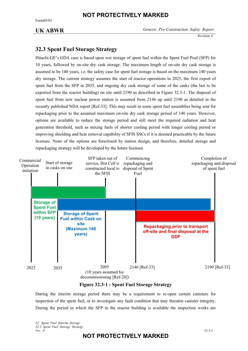
Hitachi-GE’s GDA case is based upon wet storage of spent fuel within the Spent Fuel Pool (SFP) for
10 years, followed by on-site dry cask storage. The maximum length of on-site dry cask storage is
assumed to be 140 years, i.e. the safety case for spent fuel storage is based on the maximum 140 years
dry storage. The current strategy assumes the start of reactor operations in 2025, the first export of
spent fuel from the SFP in 2035, and ongoing dry cask storage of some of the casks (the last to be
exported from the reactor building) on site until 2190 as described in Figure 32.3-1. The disposal of
spent fuel from new nuclear power station is assumed from 2146 up until 2190 as detailed in the
recently published NDA report [Ref-33]. This may result in some spent fuel assemblies being sent for
repackaging prior to the assumed maximum on-site dry cask storage period of 140 years. However,
options are available to reduce the storage period and still meet the required radiation and heat
generation threshold, such as mixing fuels of shorter cooling period with longer cooling period or
improving shielding and heat removal capability of SFIS SSCs if it is deemed practicable by the future
licensee. None of the options are foreclosed by station design, and therefore, detailed storage and
repackaging strategy will be developed by the future licensee.
Figure 32.3-1 : Spent Fuel Storage Strategy
During the interim storage period there may be a requirement to re-open certain canisters for
inspection of the spent fuel, or to investigate any fault condition that may threaten canister integrity.
During the period in which the SFP in the reactor building is available the inspection works are
2025 2095 (10 years assumed for
decommissioning [Ref-28])
2190 [Ref-33] 2035
Commercial Operation initiation
Start of storage in casks on site
SFP taken out of service, Hot Cell is constructed local to
the SFIS
Completion of repackaging and disposal
of spent fuel
Repackaging prior to transport off-site and final disposal at the
GDF
Storage of Spent Fuel within Cask on
site (Maximum 140
years)
Storage of Spent Fuel within SFP (10 years)
Commencing repackaging and disposal of Spent
Fuel
2146 [Ref-33]
NOT PROTECTIVELY MARKED Form05/01
UK ABWR Generic Pre-Construction Safety Report
Revision C
32. Spent Fuel Interim Storage 32.3 Spent Fuel Storage Strategy Ver. 0 32.3-2
NOT PROTECTIVELY MARKED
capable of being carried out within the SFP. In this case the canister would follow a reverse process to
export the canister from the reactor building to the SFIS facility and all the safety functions required
e.g. radiation shielding and containment are provided in the same manner as the export process. From
the point that SFP is no longer available, the inspection works are capable of being carried out in the
repackaging facility. It is assumed for GDA that the repackaging facility would have a hot cell for the
repackaging works and required safety functions would be provided by the repackaging facility and
the hot cell. However the ALARP demonstration depends on the final choice of SFIS detailed design
and none of the options are foreclosed, and therefore, this will be demonstrated at the appropriate
stage.
It is assumed during GDA that any damaged fuel identified during reactor operation will be stored
within the SFP until the end of generation. Due to the advancements in fuel manufacture and reactor
performance the expected number of damaged fuel pins is expected to be low. However, the potential
still exists for fuel damage to occur at some point over the 60 years life of the reactor operation.
Therefore, the strategy for damaged fuel storage during GDA is to demonstrate that there are a number
of potential solutions to handle damaged fuel of different types, within the SFIS system, ranging from
options that are currently commercially available to options that are conceptual and require research
and development before they could be deployed. This is detailed further in the topic report for GE14
Fuel Mechanical Design Report [Ref-27]. It is not considered appropriate to select a preferred option
during GDA, as the optimum solution for handling damaged fuel will depend upon the type and
quantity of damaged fuel generated during station operation. There is no envisaged scenario where
damaged fuel would need to be removed from the SFP immediately. Therefore this allows the future
licensee to develop a suitable recovery plan, other than storing the damaged fuel in an appropriate
location in the SFP. This means the licensee will have sufficient time to develop an optimum solution
for export and storage of the spent fuel. This approach also allows for the adoption of other options
and the inclusion of developing worldwide good practice as SFIS experience develops.
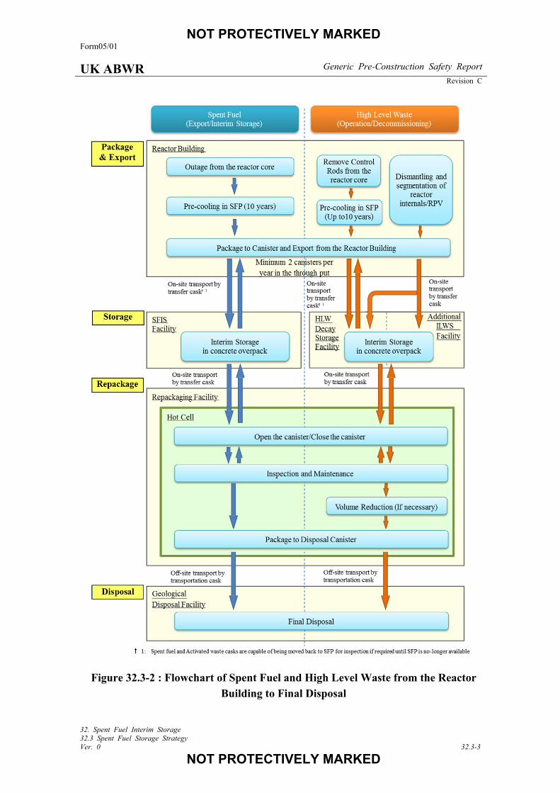
It is also considered that the repackaging facility will be commonly used for spent fuel and solid waste
– each waste stream is then diverted to its own storage facility as shown in Figure 32.3-2. The
assumed strategy for the SFIS facility and the repackaging facility is more detailed in the topic report
for SFIS [Ref-5].
NOT PROTECTIVELY MARKED Form05/01
UK ABWR Generic Pre-Construction Safety Report
Revision C
32. Spent Fuel Interim Storage 32.3 Spent Fuel Storage Strategy Ver. 0 32.3-3
NOT PROTECTIVELY MARKED
Figure 32.3-2 : Flowchart of Spent Fuel and High Level Waste from the Reactor
Building to Final Disposal
NOT PROTECTIVELY MARKED Form05/01
UK ABWR Generic Pre-Construction Safety Report
Revision C
32. Spent Fuel Interim Storage 32.3 Spent Fuel Storage Strategy Ver. 0 32.3-4
NOT PROTECTIVELY MARKED
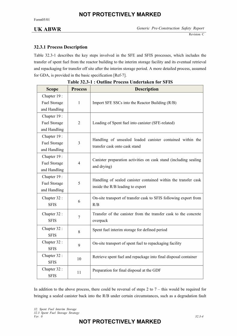
32.3.1 Process Description
Table 32.3-1 describes the key steps involved in the SFE and SFIS processes, which includes the
transfer of spent fuel from the reactor building to the interim storage facility and its eventual retrieval
and repackaging for transfer off site after the interim storage period. A more detailed process, assumed
for GDA, is provided in the basic specification [Ref-7].
Table 32.3-1 : Outline Process Undertaken for SFIS
Scope Process Description
Chapter 19 :
Fuel Storage
and Handling
1 Import SFE SSCs into the Reactor Building (R/B)
Chapter 19 :
Fuel Storage
and Handling
2 Loading of Spent fuel into canister (SFE-related)
Chapter 19 :
Fuel Storage
and Handling
3 Handling of unsealed loaded canister contained within the
transfer cask onto cask stand
Chapter 19 :
Fuel Storage
and Handling
4 Canister preparation activities on cask stand (including sealing
and drying)
Chapter 19 :
Fuel Storage
and Handling
5 Handling of sealed canister contained within the transfer cask
inside the R/B leading to export
Chapter 32 :
SFIS 6
On-site transport of transfer cask to SFIS following export from
R/B
Chapter 32 :
SFIS 7
Transfer of the canister from the transfer cask to the concrete
overpack
Chapter 32 :
SFIS 8 Spent fuel interim storage for defined period
Chapter 32 :
SFIS 9 On-site transport of spent fuel to repackaging facility
Chapter 32 :
SFIS 10 Retrieve spent fuel and repackage into final disposal container
Chapter 32 :
SFIS 11 Preparation for final disposal at the GDF
In addition to the above process, there could be reversal of steps 2 to 7 – this would be required for
bringing a sealed canister back into the R/B under certain circumstances, such as a degradation fault
NOT PROTECTIVELY MARKED Form05/01
UK ABWR Generic Pre-Construction Safety Report
Revision C
32. Spent Fuel Interim Storage 32.3 Spent Fuel Storage Strategy Ver. 0 32.3-5
NOT PROTECTIVELY MARKED
recovery and inspection. The requirement to bring the canister back to the SFP is highly unlikely,
since the design and use of the concrete cask storage system is robust, especially in conjunction with
appropriate EMIT & Ageing Management Programme (AMP) which ensures the integrity of the
canister and fuel are maintained during storage. However, the reverse process will be capable of being
implemented by the SFE and SFIS system prior to decommissioning of the reactor building. In the
unlikely event of degradation of the canister, it may be possible to recover the damage so as to ensure
containment of the spent fuel by repair welding of the canister or overpacking the canister into an
additional container within the SFIS facility. The feasible options of this reverse operation are
provided in the reports titled ‘Basic Specification of Operation Process and Equipment for Concrete
Cask Storage System’ [Ref-7] and ‘Consideration of Faults for Spent Fuel Export and Spent Fuel
Interim Storage’ [Ref-15]. All these options are not foreclosed by the design of plant and associated
SSCs. Therefore, it is feasible for the future licensee to develop these further at the appropriate stage.
The safety functions required in the processes in Table 32.3-1 are adequately provided by SFIS SSCs,
which are detailed in section 32.5.
32.3.2 Operational Experience (OPEX)
Around 40 years of favourable experience exists with the dry storage of spent fuel and about 50 years
with the dry storage of research reactor fuel. Dry storage experience exists with fuel from a variety of
reactor types (CANDU, HWR, PWR, BWR, WWER, MAGNOX and HTGR). Since its conception,
dry storage of spent fuel has evolved into a wide variety of systems. Examples of these are concrete
canisters (Argentina, Republic of Korea), metallic dual purpose casks (Germany, Japan, Spain,
Switzerland, USA), steel lined concrete containers or casks and/or casks made of ductile cast iron
(Germany, Japan, Spain, USA, UK), and concrete vault like structures (France, Hungary, UK, USA).
At the present time, many countries (Argentina, France, Germany, Hungary, Japan, Republic of
Korea, Spain, Switzerland, UK and the USA) are engaged in various dry storage technologies. Almost
all of these countries are also actively pursuing a dry storage research and development programme.
Based on the Operating Experience (OPEX) to date and the results of supporting research, the results
indicate that fuel can be stored safely for many decades [Ref-30].
Dry storage has become a mature technology and the quantities being placed into dry storage are
increasing significantly [Ref-31]. The worldwide inventory of spent fuel in dry storage up to the 1st
January 2014 was about 32,500 t (HM)2 [Ref-30].
In the USA, as many of the spent fuel storage pools are at or close to full capacity, dry storage is the
major element in the utilities` spent fuel storage strategy. As of 1 January 2013, there are 56 dry
storage facilities located at commercial reactor sites, with 18,000 t (HM) fuel in storage. On average,
approximately 200 dry storage canisters are loaded every year.
2 ‘t(HM)’ refers to the tonnage of Heavy Metal
NOT PROTECTIVELY MARKED Form05/01
UK ABWR Generic Pre-Construction Safety Report
Revision C
32. Spent Fuel Interim Storage 32.3 Spent Fuel Storage Strategy Ver. 0 32.3-6
NOT PROTECTIVELY MARKED
As the ALARP optioneering study for the spent fuel interim storage solution had concluded that a
concrete cask storage system would be the most effective solution to take forward for GDA [Ref-2],
currently available OPEX for concrete cask storage system is provided in this section.
The dominant dry storage system in the USA is the concrete cask storage system with a stainless steel
canister being used to contain the spent fuel. One of the great benefits of these systems is that the
stainless steel canisters that contain the spent fuel are dual purpose, i.e. they perform the transportation
function within a metal transportation cask for spent fuel export and are additionally designed to
perform the interim storage function when placed within the concrete cask at the reactor site. This
characteristic has allowed the concrete cask to be optimized for onsite storage, which has significantly
improved the shielding and cooling capability of these systems over the previously used metal dual
purpose casks.
These concrete cask storage systems used in the USA, the HI-TRAC and HI-STORM designs
provided by Holtec International being one of these systems widely in use, have been designed and
licensed to store spent fuel with cooling times as low as 3 years and burnups as high as 65 GWd/MTU
(maximum assembly average burnup). These short cooling times and high burnups result in maximum
allowed total canister heat loads of 46.36kW [Ref-32]. The SFIS strategy for the UK ABWR is to
store spent fuel with a minimum cooling time of 10 years and a maximum bundle average burnup less
than 65 GWd/MTU. This results in a total canister decay heat load (based upon 89 fuel assemblies) of
only 34.7kW which is less than 75 percent of the actual system decay heat capacity. For these reasons
and others, the concrete cask storage system for SFE/SFIS has been chosen for the UK ABWR.
NOT PROTECTIVELY MARKED Form05/01
UK ABWR Generic Pre-Construction Safety Report
Revision C
32. Spent Fuel Interim Storage 32.4 System Description Ver. 0 32.4-1
NOT PROTECTIVELY MARKED
System Description 32.4
This section provides the concept design regarding spent fuel storage strategy and SSCs used to allow
a reasonable assessment of the risks associated with the SFIS system. This ensures the suitability and
safety of the plans for both; long term storage of spent fuel and its transportation for final disposal.
Further description of the SFIS specific SSCs and SFIS process is provided in the Topic Report for
SFIS [Ref-5] and support document for basic specification of the concrete storage system [Ref-7].
32.4.1 Design Basis
A set of deterministic safety case requirements have been developed for the generic design for SFIS,
in order to demonstrate that the SFIS system will meet the principle described in Section 32.2.1. Since
the SFIS design will not be completed within GDA, the safety claims here should be considered as
requirements of detailed design to be developed by the future licensee.
Explanations of the safety claims relevant to the SFIS process, along with their link to the HLSFs, are
given below. The SFIS SSCs associated with each safety claim is also detailed. A detailed explanation
of the safety claims is provided in the topic report for high level safety case for SFIS [Ref-5], which,
along with the SFE/SFIS Faults topic report [Ref-15], also demonstrates that feasible options are
available for future licensee. This is further summarised in Section 32.5 of this chapter.
(1) HLSF 2-6: Functions to maintain spent fuel temperature during processes of spent fuel removal
from cask pit to storage area and during interim storage period.
[SFIS Safety Claim 2-6.1]:
Temperature of spent fuel will be maintained within specified limits such that the fuel clad does
not fail due to overheating during SFIS operations and associated fault conditions- (Cooling).
Description:
• During normal operation and following frequent faults or hazards, there shall be a single
passive means of cooling the spent fuel.
This claim relates to the following SSCs: Canister, Transfer Cask and Concrete Overpack.
The categorisation and classification for the Canister is Category A and Safety Class 1 and the
Concrete Overpack is Category B and Safety Class 2. The Transfer Cask delivers a Category C
function and is designed to meet Safety Class 3 requirements.
(2) HLSF 4-14: Functions to provide containment barrier during processes of spent fuel removal from
cask pit to storage area and during interim storage period.
[SFIS Safety Claim 4-14.1]:
NOT PROTECTIVELY MARKED Form05/01
UK ABWR Generic Pre-Construction Safety Report
Revision C
32. Spent Fuel Interim Storage 32.4 System Description Ver. 0 32.4-2
NOT PROTECTIVELY MARKED
Containment function will be maintained during SFIS operations and associated fault conditions-
(Containment).
Description:
• Multiple containment barriers for spent fuel will be maintained during normal operation and
following frequent faults and hazards, and
• Following infrequent faults and hazards, there shall be a single containment barrier for spent
fuel.
This claim relates to the following SSCs: Canister and Fuel Clad.
The categorisation and classification for the Canister is Category A and Safety Class 1. The Fuel
Clad delivers a Category C function and is designed to meet Safety Class 3 requirements.
(3) HLSF 1-10: Functions to maintain sub-criticality of spent fuel during processes of spent fuel
removal from cask pit to storage area and during interim storage period.
[SFIS Safety Claim 1-10.1]:
Fuel remains in a sub-critical condition during operations under normal and fault conditions-
(Criticality).
This claim focusses on preventing criticality from occurring and concerns the Canister Basket.
The Canister Basket delivers a Category A function and is designed to meet Safety Class 1
requirements.
(4) HLSF 4-16: Functions to provide radiation shield during processes of spent fuel removal from
cask pit to storage area and during interim storage period.
[SFIS Safety Claim 4-16.1]:
Shielding from spent fuel will reduce dose to operators and public ALARP during normal SFIS
operations and associated fault conditions- (Radiological Protection / Shielding).
This claim concerns the following SSCs: Transfer Cask, Canister Lid, Mating Device and
Concrete Overpack.
These SSCs deliver a Category A function and are designed to meet Safety Class 1 requirements.
(5) HLSF 5-16: Functions to provide handling and retrievability during processes of spent fuel
removal from cask pit to storage area and during interim storage period.
[SFIS Safety Claim 5-16.1]:
NOT PROTECTIVELY MARKED Form05/01
UK ABWR Generic Pre-Construction Safety Report
Revision C
32. Spent Fuel Interim Storage 32.4 System Description Ver. 0 32.4-3
NOT PROTECTIVELY MARKED
Handling of spent fuel within canister shall not compromise other safety functional claims and the
spent fuel and casks shall remain retrievable during normal operation and following frequent
faults- (Handling & Retrieval).
Description:
• During normal operation and following frequent faults and hazards, the spent fuel and casks
shall remain retrievable using the standard handling equipment,
• Handling during normal operation, faults and hazards shall not compromise the claims
specified for Containment, Cooling, Criticality and Radiological Protection / Shielding,
• Handling during normal operation and faults (including hazards) shall not compromise the
safety of the associated SSCs, and
• Following infrequent faults there is no requirement to use normal handling equipment.
This claim relates to the following SSCs: Canister, Transfer Cask, Concrete Overpack, Cask
Transporter Hoist and Fuel Assembly.
This function is categorised as Safety Category A and the SSCs which deliver it are designed to
meet Safety Class 1 requirements, except the Fuel Assembly which provides a Category C
function and is designed to meet Safety Class 3 requirements.
(6) HLSF 5-22: Function to limit deceleration loading to canister containment boundary during
credible cask drop faults.
[SFIS Safety Claim 5-22.1]:
Canister deceleration during design basis drop faults shall remain below allowable limits
This claim focusses on preventing failure of Canister containment boundary by limiting the
deceleration loading onto it and concerns the Impact Limiter.
The Impact Limiter delivers a Category A function and is designed to meet Safety Class 1
requirements.
The provision of impact limiters at locations where drop faults could conceivably occur results in
canister deceleration remaining below allowable limits so that the canister containment boundary is
maintained and the cask and canister can be recovered. While the impact limiters protect the canister
integrity, 100 percent fuel clad failure is conceded for sealed cask drop faults, leaving a single
containment barrier following these infrequent faults. It should be noted that many of the SFIS
systems and much of the SFIS equipment is common with that used for fuel storage and handling
during SFE. As such, most of the faults in SFIS are covered by those in SFE for which a detailed fault
schedule [Ref-15] outlines the adequate safety measures proposed. Therefore the SFCs for the
NOT PROTECTIVELY MARKED Form05/01
UK ABWR Generic Pre-Construction Safety Report
Revision C
32. Spent Fuel Interim Storage 32.4 System Description Ver. 0 32.4-4
NOT PROTECTIVELY MARKED
common SFE and SFIS equipment/systems and faults/safety measures could be claimed for SFIS in
the same manner. The relationship of the SFCs in SFE with those for SFIS is detailed in the SFIS
Topic Report for High Level Safety Case on Concept Design [Ref-5].
32.4.2 Concept Systems, Structures and Components (SSCs) Design
This section provides an outline of SFIS equipment and their respective roles.
32.4.2.1 Fuel Storage Equipment
The following SSCs will be used to hold spent fuel for SFIS. As all of these SSCs will not be required for
several years into station operation, the proof of concept only will be demonstrated at GDA. Detailed
design will be completed during the appropriate stage.
(1) Canister
The canister will be used to store fuel assemblies during the lifetime of the SFIS process. The canister
consists of two discrete components: the enclosure vessel and the fuel basket. The fuel basket maintains
geometrical arrangement of fuel in the canister, while the enclosure vessel forms a containment barrier
once sealed. The sealed canister will provide a pressurised and inert environment to maximise heat transfer
from the spent fuel to the outer canister wall.
A number of different canister designs are available for handling spent fuel as well as non-fuel components,
such as control rod blades. Canister designs that can store damaged fuel are also available. All of these
canisters can fit within the available transfer cask designs (described below) without modification to the
transfer cask or any handling equipment.
(2) Transfer cask
The transfer cask will be used to hold the canister (unloaded and loaded) while it is moved within the
reactor building, during spent fuel export from the SFP to outside the reactor building, and to transfer the
canister into a concrete overpack via a cask interface. The transfer cask is a rugged and heavy-walled
cylindrical vessel designed to contain a canister. The primary purpose of the transfer cask is to provide
shielding when fuel is held in the canister and to provide physical protection to the canister against the
consequences of a dropped load, whilst also allowing heat transfer from the fuel contained within the
canister to the environment. Suitable lifting features will be included to facilitate the handling of the
transfer cask.
(3) Concrete overpack
The concrete overpack will be used to store the canister at the SFIS facility during the interim storage
period. It will be a heavy-walled and multi-layered cylindrical vessel constructed of shielding material,
with incorporated cooling vents. As with the transfer cask, the primary purpose of the concrete overpack is
NOT PROTECTIVELY MARKED Form05/01
UK ABWR Generic Pre-Construction Safety Report
Revision C
32. Spent Fuel Interim Storage 32.4 System Description Ver. 0 32.4-5
NOT PROTECTIVELY MARKED
to reduce worker and public dose during interim storage ALARP, while providing physical protection to
the canister and maximising heat transfer from fuel.
32.4.2.2 Handling and Transfer Equipment
The following SSCs will be used to move equipment that holds spent fuel:
(1) Low Profile Transporter (LPT)
The LPT will be used to move the transfer cask and other SFIS SSCs into and out of the reactor building
via the large component entrance.
(2) Cask Transporter (CT)
The CT will be used to transfer canister/cask assemblies from the LPT once it is outside the reactor
building to the interim storage position. The CT will be a multi-wheeled or tracked, multi-directional
vehicle featuring a gantry crane and double wire hoist capable of handling a loaded transfer cask or
concrete overpack.
32.4.2.3 SFIS Ancillary Equipment
The following SFIS ancillary equipment is required for the SFIS process..
(1) Mating Device
The mating device will be used to connect the transfer cask to the concrete overpack to allow the canister to
be moved from the transfer cask to the concrete overpack. The interface provides shielding to operators
during this transfer. The device is likely to comprise two steel flanges and a sliding lid to allow the canister
to be lowered from the transfer cask into the concrete overpack.
32.4.2.4 Buildings and Facilities
The following buildings and facilities are required for SFIS operations.
(1) SFIS Facility and Storage Pads
The concrete overpacks will be stored on a seismically qualified pad within a lightweight building in order
to provide environmental shelter. The design for the SFIS facility and storage pads is site specific and is
therefore out of scope for GDA. An overview of its functional requirements is described in Section 32.6.2.1
(2) Repackaging Facility
A repackaging facility will be provided to allow removal of spent fuel from the canister after interim
storage, and to enable inspection of the fuel during interim storage from the point that the SFP is no longer
available. The repackaging work could be carried out either in wet or dry condition. Both wet and dry
methods are not foreclosed for the repackaging facility. An outline description of the repackaging facility is
provided in section 32.6.2.1 and summarised in the topic report for SFIS high level safety case [Ref-5].
NOT PROTECTIVELY MARKED Form05/01
UK ABWR Generic Pre-Construction Safety Report
Revision C
32. Spent Fuel Interim Storage 32.4 System Description Ver. 0 32.4-6
NOT PROTECTIVELY MARKED
Development of a repackaging facility design will not be completed during GDA as it will not be required
for a number of years into SFIS operations. This will allow the design to incorporate modern technology
and relevant good practice following the worldwide development of repackaging facilities.
NOT PROTECTIVELY MARKED Form05/01
UK ABWR Generic Pre-Construction Safety Report
Revision C
32. Spent Fuel Interim Storage 32.5 System Performance and Safety Features Ver. 0 32.5-1
NOT PROTECTIVELY MARKED
System Performance and Safety Features 32.5
The following section describes the key performance criteria for the SFIS system during normal operations
and fault conditions and the safety features considered to ensure the Fundamental Safety Functions (FSF)
are delivered. More detailed discussion for how the SFIS equipment and systems achieve the required
performance during normal operations is provided in the basic specification [Ref-7] and fault conditions are
provided in topic report for SFE/SFIS fault assessment [Ref-15].
32.5.1 Safety Provision for SFIS Safety Claim 2-6.1: Functions to Maintain Spent Fuel
Temperature
(1) Normal Operation (Normal Condition)
So Far As Is Reasonably Practicable (SFAIRP) the SFIS system will implement passive cooling to maintain
fuel clad temperatures below acceptable limits as specified in GE14 topic report [Ref-26]. This is enabled
by heat conduction from the spent fuel to the canister shell through the fuel basket , inert gas circulating
within the canister, and heat removal from the canister surface to the environment by natural air convection
surrounding the canister [Ref-10].
During retrieval and repackaging, claims will be placed upon appropriate cooling systems within the
repackaging facility, which are to be determined during design development at the appropriate stage.
(2) Cooling Fault
The strategy adopted for the SFIS system is to demonstrate that adequate cooling is provided to fuel
throughout the SFIS process in credible fault conditions such that clad failure does not occur or in any case
which it does, there are no radiological consequences. In this case, claims on the fuel cladding to provide a
containment barrier are maintained. Credible cooling faults in the SFIS process are:
• Leakage of inert gas from the canister due to failure of canister containment, and
• Failure of fuel clad due to blocked concrete overpack vents.
Leakage of inert gas from the canister leads to depressurisation which in turn reduces the thermal
conductivity of the gas thereby reducing the rate of heat removal from the spent fuel. Catastrophic failure
(significant breach of the pressure boundary which results in a rapid or immediate depressurisation) of the
canister is deemed incredible, and therefore this fault is judged only to occur due to a slowly developing
canister degradation fault such as by Stress Corrosion Cracking (SCC). For GDA, it is assumed the canister
containment boundary condition and temperature will be monitored during interim storage in order to
detect inert gas leakage. No method of monitoring is foreclosed to the future licensee, but could include
visual inspections or use of thermocouples to detect canister degradation and inert gas leakage as detailed
in EMIT report [Ref-8]. As such, the probability of initiation of this fault is minimised by the QA
arrangements during welding (including NDE) of the canister, the quality of the canister itself and from
periodic inspection during storage.
NOT PROTECTIVELY MARKED Form05/01
UK ABWR Generic Pre-Construction Safety Report
Revision C
32. Spent Fuel Interim Storage 32.5 System Performance and Safety Features Ver. 0 32.5-2
NOT PROTECTIVELY MARKED
Vents are provided on the concrete overpack to allow air to circulate around the canister via natural
convection which enables passive cooling of the canister. Blockage of these vents will cause a decrease in
passive cooling capability. Analysis has been conducted which shows that a 50 percent blockage would not
cause fuel clad temperatures to rise above the limits [Ref-16], therefore no failure would be conceded. As
such both the fuel clad and canister can be claimed as containment barriers. Under the hypothetical fault
condition of blockages above 50 percent the fuel clad may result in failure should the recovery action, such
as clearing the blockage or implementing other cooling methods not be carried out within the limited time.
However, it has been demonstrated in response to RQ-ABWR-1200 [Ref-29] that this does not lead to a
‘cliff edge’ effect in which all fuel clad fails as soon as the temperature limit has been reached. It is
conservatively calculated in [Ref-16] that at least 32 hours will be available for the recovery of such a fault
should 100 percent vent blockage occur. It should be noted that even in the very unlikely event of fuel
failure occurring, the canister pressure boundary is designed to withstand 100 percent fuel clad failure
[Ref-13], and therefore, there will be no release of radioactivity. It is therefore concluded that sufficient
time is available to take corrective action before fuel clad failure would occur.
In line with the above, two suitably grouped human-based safety claims (HBSCs) have been made for
actions related to the monitoring, inspection, discovery and remediation of faults in the SFIS or the casks
once they are in storage. The specific ones that relate to cask overheating are as follows: HF SFIS 2-6.1_01
and HF SFIS 2-6.1_02. The substantiation of these functional claims for a proof of concept design is not
proportionate within the GDA stage, therefore the claims are underpinned by two supporting HF property
claims, HFSPC 8 and HFSPC 10. These claims are detailed within the UK ABWR GDA HBSC Report
[Ref-35].
Safety measures against both of these faults are available as detailed in [Ref-8] and [Ref-15]. Considering
sufficient time is available for detection of the faults as described above, corrective activities can be taken
before failure of the spent fuel clad [Ref-17]. The risks associated with these faults and required detection
and recovery measures are highly dependent on the detailed design of SFIS system based on the site
specific condition. Therefore, the specific safety measures including the choice of operator intervention will
be developed further at the appropriate stage when detailed design of the SFIS systems is available.
32.5.2 Safety Provision for SFIS Safety Claim 4-14.1: Functions to Provide Containment
Barrier
(1) Normal Operation (Normal Condition)
The spent fuel clad is claimed as the first containment barrier for all normal SFIS operations. No gaseous
discharges are envisaged during normal SFIS operations.
Once the canister lid is sealed by welding, the canister is claimed as the second containment barrier during
normal SFIS operations.
NOT PROTECTIVELY MARKED Form05/01
UK ABWR Generic Pre-Construction Safety Report
Revision C
32. Spent Fuel Interim Storage 32.5 System Performance and Safety Features Ver. 0 32.5-3
NOT PROTECTIVELY MARKED
Containment features provided by the retrieval and repackaging facility will be claimed as containment
barriers during this step, which are to be determined during design development at the appropriate stage.
(2) Long Term Degradation Faults
Four faults pertaining to degradation of equipment have been identified and are all related to long term
storage within the SFIS facility. Degradation mechanisms for the materials involved in SFIS are well
understood with significant OPEX available and continual Research & Development (R&D) is being
undertaken to further this understanding. Credible faults are identified as:
• Degradation of the canister,
• Degradation of the concrete overpack,
• Degradation of fuel cladding, and
• Degradation of basket.
Degradation of the canister leads to failure of its containment function and as such this fault results in the
same consequence of insufficient cooling of fuel as the ‘leakage of inert gas’ cooling fault (Section 32.5.1).
Failure of the canister containment function also causes degradation of fuel cladding by introducing oxygen
into the canister which can result in a corrosive environment within the canister. Degradation of basket
materials is also caused by the corrosive environment introduced by failure of the canister containment.
Therefore both fuel cladding and basket degradation faults are initiated by canister containment failure. As
described in Section 32.5.1, options of safety measures to combat canister containment failure are available
[Ref-8] considering sufficient time available for detection of the faults and taking corrective activities
[Ref-17].
Degradation of the concrete overpack could reduce its shielding capability or robustness, or potentially
degrade its capacity to cool the canister. Any degradation of a concrete overpack would be slow to develop,
allowing time to respond. Monitoring of the concrete overpack would reveal damage to the overpack or
reduced cooling provided to the canister before the point at which damage to the canister or fuel contained
within would occur. The canister can be repackaged to another concrete overpack without affecting any of
the safety claims made on canister or fuel integrity. The overpack could also be locally repaired, removing
the need to move the canister.
The detailed fault assessment and demonstration that the HLSF will be maintained during this fault
condition are provided in Topic Report for Fault Assessment [Ref-15]. Options of safety measures are
available [Ref-8] and will be developed in the appropriate stage when detailed design of the SFIS system
will reduce risks ALARP.
NOT PROTECTIVELY MARKED Form05/01
UK ABWR Generic Pre-Construction Safety Report
Revision C
32. Spent Fuel Interim Storage 32.5 System Performance and Safety Features Ver. 0 32.5-4
NOT PROTECTIVELY MARKED
32.5.3 Safety Provision for SFIS Safety Claim 1-10.1: Functions to Maintain
Sub-criticality of Spent Fuel
The fuel basket design within the canister maintains fuel geometry and separates fuel assemblies to
maintain sub-criticality claims. The construction of the basket, including material selection will be
optimised to maintain sub-criticality through the use of neutron absorbing materials as described in [Ref-9].
32.5.4 Safety Provision for SFIS Safety Claim 4-16.1: Functions to Provide Radiation
Shield
(1) Normal Operation (Normal Condition)
Radiation protection/shielding is provided by SFIS SSCs: the transfer cask provides shielding during any
on-site transportation of the canister; the concrete overpack provides shielding during interim storage; and
the mating device provides shielding during the process of transferring the canister from the transfer cask to
the concrete overpack. The SFIS system is at the concept design stage during GDA and it will be designed
such that the Basic Safety Objectives (BSOs) for dose to public and workers are met for all operations and
that the design is optimised to reduce dose ALARP during appropriate stage [Ref-11].
Radiation protection/shielding features required during retrieval and repackaging will be claimed in the
systems within the repackaging facility, which are to be determined during development of the repackaging
facility design during appropriate stage.
(2) Fault conditions
Radiological protection to operators during SFIS operation is primarily provided by the transfer cask or the
concrete overpack. Dose rates exceeding normal limits are likely to be experienced by operators should a
canister loaded with irradiated fuel be inadvertently removed from the transfer cask or concrete overpack.
However, this initiating event can be eliminated by dedicating separate lifting attachments; one uniquely
designed for the transfer cask and one for the canister. This prevents erroneous lifting of canister without
transfer cask. Detailed lifting attachment specifications will be developed at the appropriate stage based on
the specifications of selected SFIS equipment design. The only credible fault identified during GDA
regarding radiation shielding is mis-placing of the mating device during the process of transferring the
canister from the transfer cask into the concrete overpack.
If a significant gap exists between the mating device and the transfer cask, or the concrete overpack does
not align, the radiation dose to the operators could exceed the normal limit. Protection against this fault will
be provided by design of the mating device such that it is incapable of incorrectly connecting to the cask
and the concrete overpack.
This will be further assessed at the appropriate stage once detailed design of the SFIS system is developed.
NOT PROTECTIVELY MARKED Form05/01
UK ABWR Generic Pre-Construction Safety Report
Revision C
32. Spent Fuel Interim Storage 32.5 System Performance and Safety Features Ver. 0 32.5-5
NOT PROTECTIVELY MARKED
32.5.5 Safety Provision for SFIS Safety Claim 5-16.1 / SFIS Safety Claim 5-22.1:
Functions to Provide Handling and Retrievability / Function to Limit
Deceleration Loading to Canister Containment Boundary
(1) Normal Operation (Normal Condition)
The SFIS specific equipment e.g. the transfer cask, the concrete overpack and the CT will provide adequate
safety features to ensure handling capability for the canister.
For retrieval and repackaging of spent fuel, systems within the repackaging facility will provide adequate
safety features to ensure handling capability for the spent fuels, which are to be determined during
development of the repackaging facility design in the appropriate stage.
For damaged fuel, the handling strategy will be to use specialist equipment to place non-retrievable fuel
into a container which reinstates handling capability, for example, a sealed container for damaged fuel. The
strategy for handling damaged fuel is addressed in the topic report for GE14 Mechanical Design Report
[Ref-27].
(2) Impact Load to Sealed Canister/Cask
A number of nuclear lifts are required during the SFIS process. The dropped cask/canister events
considered to be most onerous in the SFIS process in terms of nuclear safety are:
• Collision of transfer cask or concrete overpack with the cask transporter during transfer of the
sealed canister,
• Drop of transfer cask or concrete overpack from the cask transporter during transfer of the sealed
canister,
• Drop of the canister into the concrete overpack during transfer of the canister from the transfer
cask into the concrete overpack, and
• Drop of concrete overpack into the canister transfer pit3.
The above faults result in impact to a loaded, sealed canister and it is conservatively assumed that the fuel
cladding of each of the fuel assemblies fails as a result of the impact. Therefore the canister should
maintain its containment function so that the deterministic requirements are met. Canister structural
integrity is generally bound by a deceleration limit (60g is assumed for GDA [Ref-6]) within which the
stress limits of the canister are not exceeded and canister integrity is maintained. There would be many
reasonably practicable options to meet this requirement e.g. the speed of the cask transporter will be
limited, the cask transporter hoist will be of an appropriate reliability, an impact limiter will be utilised
during canister transfer to the overpack, etc. Considering that the safety function which should be
maintained in these faults is canister containment, the hoist well cask drop fault in the reactor building
3 The canister should be transferred into the concrete overpack from the transfer cask for interim storage. The
concrete overpack is placed in the canister transfer pit for the transfer work and it is lifted up and moved to the
storage area after the transfer is completed.
NOT PROTECTIVELY MARKED Form05/01
UK ABWR Generic Pre-Construction Safety Report
Revision C
32. Spent Fuel Interim Storage 32.5 System Performance and Safety Features Ver. 0 32.5-6
NOT PROTECTIVELY MARKED
covers all these faults because of its bounding drop height and impact load [Ref-15]. The safety case of this
fault is discussed in the Basis of Safety Case for SFE [Ref-6] in which DBA has been developed to show
that the canister integrity is maintained by an impact limiter installed on the ground floor. The DBA
demonstrates that safety measures against the impact load faults in SFIS are feasible because of much
smaller impact loads compared to the hoist well cask drop. The detailed design for SFIS equipment will not
be completed until the appropriate stage. Safety measures will be developed during the appropriate stage
with detailed design of the transfer equipment and related facilities outside of the R/B to reduce risks
ALARP.
32.5.6 Internal Hazard
The safety case for internal hazards is covered in PCSR Chapter 7, however, SFIS is not within its scope
during GDA. Identification of internal hazards once the canister leaves the R/B will be carried out at the
appropriate stage after the transfer route of the cask and equipment, and systems around the transfer route,
have been designed. For the identification of internal hazards, a consistent approach will be adopted based
on similar methodology and philosophy developed in PCSR Chapter 7. Noting that the hazard sources
which will be identified at a later stage could have an impact on safety functions of SFIS equipment and
systems, robust measures of protection or mitigation will be incorporated in detailed design of the
equipment or systems through discussions of risk reduction ALARP.
32.5.7 External Hazard
External hazards which should be considered in the UK ABWR design are defined in the PCSR Chapter 6
and detailed further in [Ref-14]. The scope of Chapter 6 includes the impact of external hazards on the
safety functions of the SFIS system. As a result, key common consequence events which could be led by
the external hazards are identified. The consequence events are: cask toppling, structural damage of
canister/cask, blockage of inlet vent and environmental temperature increase. These key faults are
identified in the fault topic report [Ref-15], which describes the impacts of these events on the safety
functions of SFIS SSCs and the safety measures available against the key faults.
32.5.8 Fault Identification and Definition
A fault schedule has been developed for the SFE and SFIS concept designs, taking into account the UK
ABWR design and the planned implementation of SFIS. The identification and sequencing process used to
generate the fault schedule is detailed in the fault topic report for SFE and SFIS [Ref-15]. Appendix A of
the fault topic report also contains the Hazard Identification (HAZID) process that was used to identify
gaps present following the existing fault identification exercise and confirm that all credible faults and
hazards had been considered. Faults that pose industrial safety risks have also been identified through the
same HAZID process and will be assessed in more detail during the appropriate stage for SFE and SFIS.
Industrial safety has additionally been considered in the ALARP optioneering assessments carried out for
SFE to ensure that the options taken forward through GDA do not present unacceptable industrial safety
risks to operators, as detailed in [Ref-3].
NOT PROTECTIVELY MARKED Form05/01
UK ABWR Generic Pre-Construction Safety Report
Revision C
32. Spent Fuel Interim Storage 32.5 System Performance and Safety Features Ver. 0 32.5-7
NOT PROTECTIVELY MARKED
Due to similar handling provisions and many shared SSCs, the faults considered within the SFE process
bound many of faults identified within the SFIS process. The only fault identified within the SFIS process
that bounds both SFE and SFIS is Fault ID 1.5 “Blocked concrete overpack vents”, as summarised in
Section 32.5.1. Detailed evaluation of this fault is provided in the Preliminary Evaluation for Heat Removal
of Loaded Cask in Fault Condition report [Ref-16], which demonstrates the temperature of spent fuel is
maintained within its limit.
It is also required that SFIS SSCs must remain recoverable under fault scenarios. This requirement is
achievable due to additional time associated with SFIS faults (for example, following a canister degradation
fault, the canister containment boundary remains intact and fuel continues to be passively cooled until it is
identified by periodic maintenance and as a result there is adequate time to devise and perform recovery
operations). This has been considered in the fault topic report [Ref-15].
The fault schedule for SFE and SFIS is given in Attachment 3 of the fault topic report [Ref-15]. This details
each credible fault associated with these processes, along with the sequence of events, estimated doses to
the workers and public and protection measures in place required to achieve the claims made.
NOT PROTECTIVELY MARKED Form05/01
UK ABWR Generic Pre-Construction Safety Report
Revision C
32. Spent Fuel Interim Storage 32.6 Spent Fuel Management at the End of Generation Ver. 0 32.6-1
NOT PROTECTIVELY MARKED
Spent Fuel Management at the End of Generation 32.6
32.6.1 EMIT and AMP
Spent fuel should be maintained in conditions such that the required safety functions are met during the
interim storage period. This includes the repackaging of fuel into final disposal vessels at the end of the
interim storage period. The required safety functions are the same as the HLSFs described in Section 32.4.1,
which are:
• Functions to maintain sub-criticality of spent fuel,
• Functions to maintain spent fuel temperature,
• Functions to provide containment barrier,
• Functions to provide radiation shield,
• Functions to provide handling and retrievability, and
• Function to limit deceleration loading to canister containment boundary during credible cask drop
faults.
To achieve these, EMIT and the AMP for the SFIS system is required to detect any fault conditions on the
stored canister and to take corrective actions. As detailed specification or design of the SFIS SSCs will not
be completed during GDA, possible options for EMIT and AMP are demonstrated in the topic report for
EMIT and AMP [Ref-8], such as:
• Peening treatment of canister welds to reduce the residual tensile stresses and hence mitigate
against Stress Corrosion Cracking (SCC) and subsequent loss of containment and cooling,
• Monitoring of canister temperature to detect loss of containment and cooling of the canister, and
• Monitoring of concrete overpack surface to detect degradation of shielding.
Feasibility of the options is also addressed within the topic report.
32.6.2 Removal from Site
32.6.2.1 Overview of SFIS Facility
The spent fuel canisters exported from the reactor building will be stored temporarily within the SFIS
facility unlike the usual US practice of storing them outside with no environmental protection. The SFIS
facility which is currently a concept for the UK-ABWR GDA will have this capability in order to further
reduce the risks during storage of spent fuel. Within the timeframe assumed for interim storage and prior to
repackaging, the SFIS facility design features will ensure Safety Claims placed on SFIS-related SSCs are
fulfilled. Since the detailed design of this facility is not available during GDA, specific functional claims,
arguments, and related evidence will be developed later, at an appropriate stage. However, an overview of
its functional requirements is described in this section.
All fundamental safety functions for SFIS are placed on the SSCs themselves, i.e. the concrete overpack,
canister and fuel basket. As such, no fundamental safety claims are placed on the storage facility itself,
however the design of facility, such as building slab, will be seismically qualified to ensure that the safety
claims on the SSCs can be fulfilled. The SFIS facility will, however, have the following basic functions: to
NOT PROTECTIVELY MARKED Form05/01
UK ABWR Generic Pre-Construction Safety Report
Revision C
32. Spent Fuel Interim Storage 32.6 Spent Fuel Management at the End of Generation Ver. 0 32.6-2
NOT PROTECTIVELY MARKED
receive the transfer cask and canister; and transfer the canister to the concrete overpack; and the reverse
process; and to provide for the adequate storage of the loaded concrete overpacks. These functions can be
further detailed as follows:
• Provide a suitable storage space to house all the spent fuel to be generated during operation,
• Provide a transfer area to facilitate the transfer of the loaded canister to/from the concrete
overpacks with the use of the on-site cask transporter. The transfer area should be sized to also
allow the transfer for the canister to a metal cask or suitable overpack to re-establish the
containment boundary, should this approach be chosen,
• Protect the loaded concrete overpacks from the environment to appropriate level while allowing
for sufficient ambient air flow to support cooling and minimizing the potential impact of a
collapse of the SFIS structure due to severe external hazards, and
• Allow for EMIT and potential recovery actions to be performed on the loaded concrete overpacks
and canisters following a degradation fault.
Therefore, it is considered that no novel or unusual design features are required for the SFIS facility. This
will ensure feasible facility options are available for future licensee, and therefore, the associated risks are
capable of being reduced ALARP. The design options for the SFIS facility are described further in Topic
Report on SFIS [Ref-5].
32.6.2.2 Overview of Repackaging Facility
A repackaging facility will be provided for repackaging of the spent fuel and non-fuel components from the
storage canisters into final disposal containers. The facility may also be used, from the point the spent fuel
pool is no longer available, for inspection of the storage canisters, spent fuels and non-fuel components,
including recovery activities in case any faults are identified during inspections. OPEX and example
designs are available worldwide for both wet and dry methods [Ref-18]. This section provides an overview
of the repackaging facility and its requirements based on an example dry method to demonstrate its
feasibility. However, it should be noted that the SFIS system is at concept design level during GDA and
that a detailed safety case with risks reduced ALARP for the repackaging facility will be developed during
the appropriate stage.
It is currently assumed that the facility will have the following capabilities:
• Interface with on-site transporter to accept the canister and to deliver a complete package (i.e.
canister, transfer cask, concrete overpack or container) for final disposal,
• Inspection of concrete overpack, transfer cask and canister (and spent fuel if necessary),
• Overpack a canister, or potentially perform repair welding (if inspection determines
re-establishment of the containment barrier is necessary),
• Opening of the cask/canister following necessary preparation,
• Verify and retrieve designated fuel from specified locations in the cask/canister,
• Provide capability for remote inspection of fuel assemblies,
• Place fuel into designated location (i.e. back into same or into new cask/canister),
NOT PROTECTIVELY MARKED Form05/01
UK ABWR Generic Pre-Construction Safety Report
Revision C
32. Spent Fuel Interim Storage 32.6 Spent Fuel Management at the End of Generation Ver. 0 32.6-3
NOT PROTECTIVELY MARKED
• Backfill with inert gas, close and inspect cask/canister,
• Process excess packaging materials and any waste generated during the operation, and
• Package spent fuel into final disposal containers before fuel is exported from site to GDF.
Implementation of this generic process will differ following detailed design of SFIS SSCs and other
site-specific constraints. Therefore, demonstration of specific arguments underpinning the fulfilment of
Safety Claims for these functions is not realistic during GDA. However, as also described in Appendix A of
the Dry Transfer System (DTS) research report from US DOE [Ref-18], feasible options are available.
Based on this, the SFIS system design, including the repackaging facility, is considered feasible and the
associated risks are capable of being reduced ALARP.
Considering the facility is planned to be built prior to the start of station decommissioning, and should be
available until all spent fuel has been transported to the off-site GDF at the end of the SFIS period, the
following requirement should be considered for the facility:
• A facility maintenance strategy shall be in place to ensure that all required functions for
inspection and repackaging activities remain available until facility decommissioning.
Radiation shielding and containment functions could be achieved by providing a hot cell in which canister
and direct spent fuel handling could be carried out. The hot cell should be provided with handling
capability for removal of a loaded canister from concrete overpack/loading of final disposal canister into
transport cask, de-lidding the canister/re-lidding of the disposal canister, removing spent fuels from the
canister/loading of the spent fuels into the final disposal container. The cell would need a system to control
the environmental condition inside, e.g. cooling of the spent fuels, maintenance of inert condition, and an
import/export cell with an airlock.
Equipment for remote inspections of the canister or spent fuel should be provided in the hot cell. Possible
inspection technologies are: visual examination of the canister or spent fuel or gas sampling (sipping) of the
canister to detect fission gases and therefore failed fuel. Detailed specification of the inspection equipment
will be developed based on the specific constraints applied to, and preferences of, the future licensee. To
ensure no foreclosure of the possible inspection method, enough space for the equipment and required
services e.g. electric power, pressurised air, pure water, systems for effluent treatment and ventilation,
should be maintained within the concept design.
The capacity to treat canisters for feasible faults is an important requirement of the facility design. However,
this will largely depend on the size of the facility and will be considered according to the detailed
requirements and constraints of repackaging and disposal of the spent fuel during an appropriate stage.
A review of possible designs of the facility are available in referenced documents (e.g. provided by the
Nuclear Decommissioning Authority (NDA) [Ref-23]). In this report, a concept structure for the facility is
provided with estimated costs. The technology required for this facility is not novel and is relatively simple.
The design of the repackaging facility is not foreclosed to the future licensee by the assumptions set out
within the GDA. Development of a repackaging facility design will not be completed during GDA as it will
not be required for a number of years into SFIS operations and continued development of the facility
should not be foreclosed. This will allow incorporation of modern technology through the facility lifetime
NOT PROTECTIVELY MARKED Form05/01
UK ABWR Generic Pre-Construction Safety Report
Revision C
32. Spent Fuel Interim Storage 32.6 Spent Fuel Management at the End of Generation Ver. 0 32.6-4
NOT PROTECTIVELY MARKED
and therefore build upon good practice which is developed from other repackaging facilities around the
world.
32.6.2.3 Disposability
The disposability of UK ABWR spent fuel is discussed in the RWM Disposability Report in which
requirements for spent fuel interim storage are addressed [Ref-23]. For further details on the RWM
disposability assessment for spent fuel see PCSR Chapter 18, Section 18.1.1: Disposability.
At the end of generation the strategy and plan for dealing with the spent fuel until the disposal route is
available is detailed in Chapter 31, Sections 31.6: Decommissioning Strategy and Section 31.7:
Decommissioning Plan. This chapter, along with Chapters 18 and 31 demonstrate that there are viable
disposal options and routes available, and therefore, it is capable of being disposable by the future licensee.
Adequate spent fuel cooling and handling capability are key requirements for disposability. Canister
integrity during the interim storage period also has the key role for these requirements. These have been
demonstrated in Section 32.5 of this PCSR and The EMIT report [Ref-8] sets out the available management
and inspection options for SFIS SSCs to maintain canister and fuel clad integrity throughout the interim
storage period.
32.6.3 Decommissioning Plan
Decommissioning of the SFIS system will occur after the end of the interim storage period when all spent
fuel has been exported off-site for final disposal to GDF. Detailed safety cases for SFIS system
decommissioning should be developed in the future before the decommissioning to incorporate the latest
OPEX and practices available at the time from other similar facilities worldwide.
NOT PROTECTIVELY MARKED Form05/01
UK ABWR Generic Pre-Construction Safety Report
Revision C
32. Spent Fuel Interim Storage 32.7 Spent Fuel Management Arrangements for SFIS Ver. 0 32.7-1
NOT PROTECTIVELY MARKED
Spent Fuel Management Arrangements for SFIS 32.7
32.7.1 Records Management
The UK ABWR site will have the ability to track fuel from import to the station to spent fuel disposal at GDF.
The spent fuel management and storage facilities described in this PCSR are based on the assumption that each
fuel bundle has a unique serial ID, and cores and racks have unique addresses for each location in order to enable
fuel tracking. Furthermore, the storage system is assumed to have the ability to uniquely identify containers. This
data will inform the QA records for final disposal.
It is assumed that individual package QA records will be appropriate to satisfy site licence conditions,
environmental permit requirements and disposal facility acceptance criteria. The records shall include, but
are not limited to, the following:
• Unique package identification number,
• Unique storage location where appropriate,
• Description of waste contents (including quantity where appropriate),
• Source of waste,
• Total package mass,
• Radiological information (contents radioactivity, surface contamination levels and final Assay
records),
• Supplier Certificate of Conformity for package, and
• Details of any periodic inspections during the interim storage period.
The future licensee is responsible for developing their own management system based on their
requirements, using fuel bundle ID and any address of location in racks, cores, etc. The future licensee’s
tracking system will keep the QA records from the donor facilities along with the records of the package
storage location until the spent fuel is dispatched from site. Records of all packages shall be retained for the
life of the plant or until the spent fuel is received by the GDF, whichever is longer. A system for recording
this type of information is currently utilized many nuclear power plants worldwide, and therefore there is
OPEX available to the future licensee to develop the system.
32.7.2 Change Control
It is possible that the fundamental assumptions for the GDA stage of design may change as a result of
future operational requirements and facility modifications. Foreseeable changes are determined to be:
• the required fuel quantity and/or life extensions,
• evolution of the fuel design over the operational lifetime of facilities, and
• the requirement to store other items.
As such, the SFIS system and facilities will be designed to be capable of accommodating these foreseeable
changes by the future licensee at the appropriate stage. Changes to the specifications and condition of spent
fuels would have effects on the specifications of the cask/canister and the storage area. However, there
would be sufficient time to take action to accommodate these changes before the results of these changed
NOT PROTECTIVELY MARKED Form05/01
UK ABWR Generic Pre-Construction Safety Report
Revision C
32. Spent Fuel Interim Storage 32.7 Spent Fuel Management Arrangements for SFIS Ver. 0 32.7-2
NOT PROTECTIVELY MARKED
come into effect. It is considered that any of the foreseeable changes will not result in onerous conditions,
considering many SFIS systems are in use for a wide range of fuel specifications and conditions and
therefore relevant OPEX and good practice can be drawn on to resolve any future issues which may arise.
NOT PROTECTIVELY MARKED Form05/01
UK ABWR Generic Pre-Construction Safety Report
Revision C
32. Spent Fuel Interim Storage 32.8 Assumptions, Limits and Conditions for Operation Ver. 0 32.8-1
NOT PROTECTIVELY MARKED
Assumptions, Limits and Conditions for Operation 32.8
32.8.1 Purpose
One purpose of this generic PCSR is to identify constraints that must be applied by a future licensee of a
UK ABWR plant to ensure safety during normal operation, fault and accident conditions. This applies to
the scope of GDA, and primarily Class 1 and 2 for SSCs. The general principles are defined in Generic
PCSR Chapter 4, Section 4.12.
This section provides a summary of the Assumptions and LCOs that apply specifically to the scope of this
chapter of the PCSR.
32.8.2 LCOs Specified for SFIS System
As stated in SFIS TR [Ref-5], the key LCOs associated with SFIS (relating to criticality, containment, fuel
cooling) are described in the relevant supporting documents. The SFIS process is at an early stage of
concept design and the export of spent fuel will not happen until 10 years after the start of reactor
generation, therefore the limits and conditions for operation have not yet been defined. While the
requirements to develop the LCOs and surveillance systems have been recognised, defining them is beyond
the scope of the GDA because detailed information regarding the chosen spent fuel storage technology is
required. Therefore these will be detailed further in the appropriate stage.
32.8.3 Assumptions for SFIS System
A number of working assumptions are made to demonstrate that the SFIS system will achieve all safety
claims and that nuclear safety aspects have been adequately considered in the GDA process. These
assumptions are not final design decisions, but have been made in order to allow development of an
adequate case during GDA. The key working assumptions for the SFIS system include:
• The fuel storage canister will be similar in design to the canister design supplied by Holtec
International,
• The canister will hold up to 89 spent fuel assemblies,
• The transfer cask and concrete overpack designs will be similar to the available HI-TRAC and
HI-STORM designs provided by Holtec International,
• Transfer of the canister between the transfer cask and the concrete overpack will take place
outside the R/B – and so canisters are exported from the R/B in a transfer cask,
• A loaded cask can be returned to the SFP for unloading while it is available (should the need
arise),
• Fuel type: Boiling Water Reactor (BWR) fuel assembly (GE14),
• Pool cooling period: 10 years,
• The damaged fuel identified during reactor operation will be stored within the SFP until the end of
generation followed by packaging, transport and storage in the SFIS,
• Following wet storage of spent fuel within the Spent Fuel Pool (SFP) for 10 years, there will be
on-site dry cask storage within SFIS. The maximum length of on-site dry cask storage will be 140
years, i.e. the safety case for spent fuel storage is based on maximum 140 years dry storage,
NOT PROTECTIVELY MARKED Form05/01
UK ABWR Generic Pre-Construction Safety Report
Revision C
32. Spent Fuel Interim Storage 32.8 Assumptions, Limits and Conditions for Operation Ver. 0 32.8-2
NOT PROTECTIVELY MARKED
• Following SFIS, spent fuel will be repackaged into disposal containers utilizing hot cells prior to
disposal.
• Spent fuel is disposable in the Geological disposal facility. The ability to retrieve, inspect and
repackage will be maintained throughout the period spent fuel is on the site,
• There will be a single inspection / maintenance / repackaging facility for spent fuel and HLW,
• The HLW will be segregated from the spent fuel within the SFIS or in a separate facility that will
be co-located with the HLW, and
• The funded decommissioning programme base case [Ref-1] sets out a number of assumptions
regarding the means by which waste may be managed and disposed of and decommissioning
carried out by a future licensee. These assumptions define a generic lifecycle plan for new nuclear
power stations known as the “Base Case”. The Base Case is built on existing policy and
regulatory requirements; although it also makes additional assumptions. The Base Case is
primarily written to ensure sufficient financial provision is made to cover liabilities. It also
provides each future licensee basic assumptions on which radioactive waste management,
decommissioning and spent fuel management strategies can be developed from, for example the
Base Case assumes that new nuclear power stations will use uranium or uranium oxide fuel.
These are detailed in Topic report on SFIS system [Ref-5] and have been summarised in Assumptions and
Requirements List [Ref-34] to be updated to align with contents of PCSR Rev.C.
NOT PROTECTIVELY MARKED Form05/01
UK ABWR Generic Pre-Construction Safety Report
Revision C
32. Spent Fuel Interim Storage 32.9 Summary of ALARP Justification Ver. 0 32.9-1
NOT PROTECTIVELY MARKED
Summary of ALARP Justification 32.9
This section presents a high level overview of how the ALARP principle has been applied for spent fuel
interim storage and how this contributes to the overall ALARP argument for the UK ABWR.
Generic PCSR Chapter 28 : ALARP Evaluation, presents the high level approach taken for demonstrating
ALARP across all aspects of the design and operation. It presents an overview of how the UK ABWR
design has evolved, the further options that have been considered across all technical areas resulting in a
number of design changes and how these contribute to the overall ALARP case. The approach to
undertaking ALARP assessment during GDA is described in the GDA ALARP Methodology [Ref-19] and
Safety Case Development Manual [Ref-20].
The efficiency with which the nuclear fuel is used in the UK ABWR and the frequency with which it is
changed will influence the amount of spent fuel which is generated during operations [Ref-21]. Worldwide
operational experience has been used in order to minimise the amount of spent fuel generated by the UK
ABWR, however the generation of spent fuel waste is inevitable.
The anticipated timescales for the management of spent fuel extend long after the reactor has ceased
operation. Within these timescales, Hitachi-GE ensures safety at all times from production to preparation
for disposal. This includes the interim storage, within the appropriate timescales e.g. ensuring safety at all
times, until safe disposal. The SFIS process covers all aspects of fuel handling between the equipment
entrance door of the reactor building and the interim storage location. It also covers retrieval and
repackaging of fuel following the interim storage period. The spent fuel management is part of the
integrated waste strategy [Ref-22]. The generation of spent fuel, its safe management and subsequent
treatment is such that a disposability assessment has concluded that the spent fuel could be disposed of in
the GDF [Ref-23].
In line with Relevant Good Practice, the spent fuel is managed in a manner that minimises the need for
future processing, is stored in accordance with good engineering practice and in a condition of passive
safety. Monitoring, examination, inspection and testing have been considered in GDA [Ref-8] and can be
used the interim store for the anticipated storage duration.
In order to determine an appropriate SFIS solution for the UK ABWR, an optioneering study was
undertaken [Ref-2]. Various in-service and concept interim storage solutions were reviewed and scored
against an optioneering scoring system to define the most suitable option for the UK ABWR design
(Attachment 1 of[Ref-2]). The option adopted was a concrete cask storage solution. An SFIS building will
be provided around the concrete overpack storage location to provide environmental protection and heat
dissipation capability to the SFIS system during interim storage. It should be noted that none of the passive
storage systems currently available can be transported to the GDF directly and hence the requirement for
repackaging.
NOT PROTECTIVELY MARKED Form05/01
UK ABWR Generic Pre-Construction Safety Report
Revision C
32. Spent Fuel Interim Storage 32.9 Summary of ALARP Justification Ver. 0 32.9-2
NOT PROTECTIVELY MARKED
The concrete overpack solution has been adopted at numerous nuclear sites around the world, most notably
in the US. The solution provides a passively safe storage solution which protects fuel from damage during
interim storage while maintaining operator and public dose within acceptable levels.
Based on the interim storage solution determined by the optioneering study [Ref-2], a risk assessment was
undertaken to identify potential faults and hazards associated with the SFIS process. The identification and
sequencing process used to generate the fault schedule is detailed in the fault topic report for SFE and SFIS
[Ref-15]. Appendix A of the fault topic report also contains the HAZID process that was used to identify
gaps present following the existing fault identification exercise and confirm that all credible faults and
hazards had been considered.
Following interim storage the fuel will be repackaged and transferred to an offsite long term fuel storage
location. As for UK ABWR, the design for the repackaging facility is being discussed and developed at this
stage (section 32.6.2.2). However, there are some useful referenced concept or completed designs of
repackaging facilities used internationally [Ref-18], [Ref-24]. According to these references, it has been
determined that a repackaging facility requires nuclear safety functions such as shielding, and containment,
and the options to maintain these functions are not foreclosed. The repackaging facility will allow the
removal of fuel from the canister for repackaging into new storage devices for transport to GDF, which is
the UK long term storage location.
The design of the spent fuel interim storage site for the UK ABWR will follow UK and international good
practice and, following systematic and comprehensive options studies, all reasonably practicable risk
reduction measures will have been adopted. In addition, the OPEX will be used to inform future cask
selection and detailed design for SFIS by the future licensee. The risks from the spent fuel systems are
therefore capable of being reduced ALARP.
NOT PROTECTIVELY MARKED Form05/01
UK ABWR Generic Pre-Construction Safety Report
Revision C
32. Spent Fuel Interim Storage 32.10 Conclusions Ver. 0 32.10-1
NOT PROTECTIVELY MARKED
Conclusions 32.10
This chapter of the PCSR demonstrates that the concept for SFIS presented within GDA is feasible and that
risks are capable of being reduced ALARP. The spent fuel management is part of a strategy which is
integrated with other strategies, such as decommissioning, and which is consistent with government policy.
The spent fuel strategy is based upon the UK Government Funded Decommissioning Programme (FDP)
Guidance [Ref-1] base case assumption that the spent fuel from new nuclear power stations will be
disposed of in the Geological Disposal Facility (GDF) that the Government will construct to dispose of
Higher Activity Wastes (HAW). Therefore, following a period of cooling in the spent fuel pool the spent
fuel is placed into interim storage, repackaged and disposed of in the UK GDF. The disposability
assessment concludes that the spent fuel could be disposed of in the GDF [Ref-23].
SFIS operations will not be required until sufficient spent fuel has been generated by an operating station
and cooled in the Spent Fuel Pool (SFP) for an appropriate time. Therefore detailed design of the SFIS
SSCs will not be completed until after the GDA process is complete. This allows for the SFIS process to
benefit from worldwide experience and developing good practice which can be incorporated into the design.
This is in line with regulatory guidance contained in ONR letter REG-HGNE-0026N [Ref-25].
Therefore this chapter has provided proof of concept for the SFIS as part of the overall UK ABWR design
and demonstrates that options to the future licensee for SFIS are not foreclosed. The approach adopted for
the SFIS design in GDA for the UK ABWR is based on current commercially available technology as a
concept SFIS system, but which still allows the future licensee to take advantage of adopting relevant good
practice and technology which may become available in the future.
During GDA the generic SFIS approach was considered and an ALARP optioneering study was conducted
on the storage solution for SFIS [Ref-2]. The result of this study was that a concrete cask storage system,
consistent with international good practice was adopted as the most effective solution to take forward for
GDA. This formed the basis for further design assessment and development during GDA and provided a
framework for further optioneering to provide a reference SFIS solution that is capable of reducing risks
ALARP.
The safety cases for SFIS in this chapter together with Spent Fuel Export in Chapter 19 demonstrate that
the SFIS system can be safely integrated in to the UK ABWR and that risks associated with the design and
operation of the SFIS systems for the UK ABWR are capable of being reduced ALARP. It is acknowledged
that further work will be required post-GDA to develop the SFIS system design and fully incorporate site
specific aspects. This work will be the responsibility of any future licensee and operator.
This chapter and its supporting documentation provide a basis of SFIS design to be developed further by
the future licensee.
NOT PROTECTIVELY MARKED Form05/01
UK ABWR Generic Pre-Construction Safety Report
Revision C
32. Spent Fuel Interim Storage 32.11 References Ver. 0 32.11-1
NOT PROTECTIVELY MARKED
References 32.11
[Ref-1] Department of Energy and Climate Change, “Funded Decommissioning Programme Guidance
for New Nuclear Power Stations”, December 2011.
[Ref-2] Hitachi-GE Nuclear Energy, Ltd., “High Level Optioneering on Spent Fuel Interim Storage”,
GA91-9201-0003-00458 (FRE-GD-0019) Rev.0, March 2015.
[Ref-3] Hitachi-GE Nuclear Energy, Ltd., “Spent Fuel Interim Storage Optioneering for Spent Fuel
Removal from Spent Fuel Pool to Outside of Reactor Building”, GA91-9201-0003-00689
(FRE-GD-0080) Rev.3, September 2016.
[Ref-4] Hitachi-GE Nuclear Energy, Ltd., “ALARP Report for Spent Fuel Export”,
GA91-9201-0003-01563 (FRE-GD-0144) Rev.0, September 2016.
[Ref-5] Hitachi-GE Nuclear Energy, Ltd., “Topic Report for High Level Safety Case on Concept Design
of Spent Fuel Interim Storage system”, GA91-9201-0001-00244 (FRE-GD-0042) Rev.2,
November 2016.
[Ref-6] Hitachi-GE Nuclear Energy, Ltd., “Preliminary Basis of Safety Case on Spent Fuel Export
System”, GA91-9201-0003-01562 (FRE-GD-0146) Rev.1, July 2017.
[Ref-7] Hitachi-GE Nuclear Energy, Ltd., “Basic Specification of Operation Process and Equipment for
Concrete Cask Storage System”, GA91-9201-0003-00437 (FRE-GD-0040) Rev.5, April 2017.
[Ref-8] Hitachi-GE Nuclear Energy, Ltd., “Maintenance of Integrity of SFIS Systems Structures and
Components during Interim Storage with EMIT and AMP”, GA91-9201-0003-00539
(FRE-GD-0068) Rev.0, May 2015.
[Ref-9] Hitachi-GE Nuclear Energy, Ltd., “Preliminary Evaluation for Subcriticality Safety”,
GA91-9201-0003-00501 (FRE-GD-0053) Rev.1, April 2015.
[Ref-10] Hitachi-GE Nuclear Energy, Ltd., “Preliminary Evaluation for Heat Removal of Loaded Cask in
Normal Operation”, GA91-9201-0003-00500 (FRE-GD-0052) Rev.0, January 2015.
[Ref-11] Hitachi-GE Nuclear Energy, Ltd., “Public and Worker Dose Evaluation, Zoning and Radiation
Shielding of SFIS System during Normal Operation (Methodology and Example)”,
GA91-9201-0003-00632 (HE-GD-5105) Rev.1, November 2016.
[Ref-12] Hitachi-GE Nuclear Energy, Ltd., “Summary of CAE Tree for Spent Fuel Interim Storage”,
GA91-9201-0003-02189 (FRE-GD-0183) Rev.0, June 2017.
[Ref-13] Hitachi-GE Nuclear Energy, Ltd., “Preliminary Evaluation for Containment Safety”,
GA91-9201-0003-00607 (FRE-GD-0064) Rev.1, July 2016.
[Ref-14] Hitachi-GE Nuclear Energy, Ltd., “Consideration of External Hazard for Spent Fuel Export and
Spent Fuel Interim Storage”, GA91-9201-0003-00527 (FRE-GD-0056) Rev.1, May 2016.
[Ref-15] Hitachi-GE Nuclear Energy, Ltd., “Consideration of Faults for Spent Fuel Export and Spent Fuel
Interim Storage”, GA91-9201-0003-00526 (FRE-GD-0057) Rev.4, July 2017.
[Ref-16] Hitachi-GE Nuclear Energy, Ltd., “Preliminary Evaluation for Heat Removal of Loaded Cask in
Fault Condition”, GA91-9201-0003-00525 (FRE-GD-0054) Rev.2, April 2017.
NOT PROTECTIVELY MARKED Form05/01
UK ABWR Generic Pre-Construction Safety Report
Revision C
32. Spent Fuel Interim Storage 32.11 References Ver. 0 32.11-2
NOT PROTECTIVELY MARKED
[Ref-17] Hitachi-GE Nuclear Energy, Ltd., “Spent Fuel Cladding Temperatures Following Cask Failure
(Response to RQ-ABWR-0872)”, GA91-9201-0003-01403 (UE-GD-0565) Rev.0, June 2016.
[Ref-18] Brett W. Carlsen and Michaele BradyRaap, US. DOE IDAHO NATIONAL LABORATORY,
“Dry Transfer Systems for Used Nuclear Fuel”, May 2012.
[Ref-19] Hitachi-GE Nuclear Energy, Ltd., “GDA ALARP Methodology”, GA10-0511-0004-00001
(XD-GD-0037) Rev.1, November. 2015.
[Ref-20] Hitachi-GE Nuclear Energy, Ltd., “GDA Safety Case Development Manual”,
GA10-0511-0006-00001 (XD-GD-0036) Rev.3, June. 2017.
[Ref-21] Hitachi-GE Nuclear Energy, Ltd., “Demonstration of BAT”, GA91-9901-0023-00001
(XE-GD-0097) Rev.F, July. 2016.
[Ref-22] Hitachi-GE Nuclear Energy, Ltd., “Integrated Waste Strategy”, GA91-9201-0003-00425
(WE-GD-0050) Rev.3, July. 2017.
[Ref-23] Nuclear Decommissioning Authority, Radioactive Waste Management Directorate, “Generic
Design Assessment: Summary of Disposability Assessment for Wastes and Spent Fuel arising
from Operation of the UK ABWR”, RWM Technical Note No.23383092, November 2016.
[Ref-24] Rob Howard, US. DOE-NE Nuclear Fuels Storage and Transportation Planning Project,
“Implications of Repackaging Used Nuclear Fuel”, U.S. Nuclear Waste Technical Review Board,
Technical Workshop, November 2013.
[Ref-25] ONR Letter, “The regulator’s expectations on the required level of design of spent fuel & waste
plants in the Generic Design Assessment”, REG-HGNE-0026N, May 2014.
[Ref-26] Hitachi-GE Nuclear Energy, Ltd., “GE14 Fuel Integrity Evaluation during Interim Storage”,
GA91-9201-0003-00200 (UE-GD-0253) Rev.2, July. 2017.
[Ref-27] Hitachi-GE Nuclear Energy, Ltd., “GE14 Fuel Mechanical Design Report”,
GA21-3809-0012-00001 (UE-GD-0090) Rev.2, November 2016.
[Ref-28] Hitachi-GE Nuclear Energy, Ltd., “Topic Report on Decommissioning: Decommissioning
Strategy”, GA91-9201-0001-00175 (DCE-GD-0064) Rev.3, July 2017.
[Ref-29] Hitachi-GE Nuclear Energy, Ltd., “Full Response to RQ-ABWR-1200 (Overpack vent blockages
during SFIS)”, January 2017.
[Ref-30] “Spent Fuel Performance Assessment and Research: Final Report of a Coordinated Research
Project on Spent Fuel Performance Assessment and Research (SPAR-III) 2009–2014”,
IAEA-TECDOC-1771.
[Ref-31] EPRI “Industry Spent Fuel Storage Handbook”, EPRI, Palo Alto, CA, 2010, Report No. 102048.
[Ref-32] Holtec International, “Final Safety Analysis Report on the HI-STORM FW System”, Holtec
Report No. HI-2114830.
[Ref-33] Nuclear Decommissioning Authority, Radioactive Waste Management Directorate, “Geological
Disposal: Implications of the 2013 Derived Inventory on the Disposal System Safety Case”,
NDA/RWM/129, July 2015.
NOT PROTECTIVELY MARKED Form05/01
UK ABWR Generic Pre-Construction Safety Report
Revision C
32. Spent Fuel Interim Storage 32.11 References Ver. 0 32.11-3
NOT PROTECTIVELY MARKED
[Ref-34] Hitachi-GE Nuclear Energy, Ltd., "Comprehensive list in GDA for requirement & assumptions
to be transferred to operating regime", GA91-9201-0003-02055 (XD-GD-0049), Rev.1, August
2017.
[Ref-35] Hitachi-GE Nuclear Energy, Ltd., “Human-Based Safety Claims Report”,
GA91-9201-0001-00043 (HFE-GD-0064), Rev.D, July 2017.
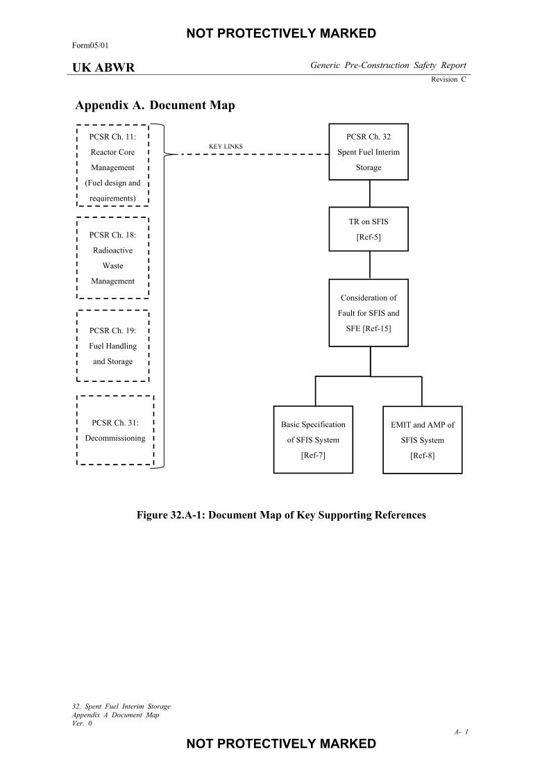
NOT PROTECTIVELY MARKED Form05/01
UK ABWR Generic Pre-Construction Safety Report
Revision C
32. Spent Fuel Interim Storage Appendix A Document Map Ver. 0
A- 1
NOT PROTECTIVELY MARKED
Appendix A. Document Map
Figure 32.A-1: Document Map of Key Supporting References
KEY LINKS
PCSR Ch. 32
Spent Fuel Interim
Storage
PCSR Ch. 19:
Fuel Handling
and Storage
PCSR Ch. 18:
Radioactive
Waste
Management
PCSR Ch. 31:
Decommissioning
TR on SFIS
[Ref-5]
Consideration of
Fault for SFIS and
SFE [Ref-15]
Basic Specification
of SFIS System
[Ref-7]
EMIT and AMP of
SFIS System
[Ref-8]
PCSR Ch. 11:
Reactor Core
Management
(Fuel design and
requirements)
Recommended


![UK ABWR Generic Design Assessment - UK Advanced Boiling ...E10]UKABWR-GA... · Form10/00 . Hitachi-GE Nuclear Energy, Ltd. UK ABWR . UK ABWR Generic Design Assessment Alignment with](https://img.pdfslide.us/doc/110x75/5cc164e988c9936f648c4e74/uk-abwr-generic-design-assessment-uk-advanced-boiling-e10ukabwr-ga.jpg)


![UK ABWR Generic Design Assessment · 12/14/2017 · XE-GD-0099, Rev F, August 2017. [Ref-4] Department of Energy & Climate Change, “National Policy Statement for Nuclear Power](https://img.pdfslide.us/doc/110x75/5f4e5375eca242592c62d22e/uk-abwr-generic-design-12142017-xe-gd-0099-rev-f-august-2017-ref-4-department.jpg)

![UK ABWR Generic Design AssessmentE03]UKABW… · 5.3. Gathering Evidence ... Candidate Nuclear Power Plant Designs”, version 3, October 2016. [Ref-2] Hitachi-GE Nuclear Energy,](https://img.pdfslide.us/doc/110x75/5f761fed3e57827b5e4aacbd/uk-abwr-generic-design-e03ukabw-53-gathering-evidence-candidate-nuclear.jpg)