Relief valves (Always refer to the relief valve manufacturer for specific settings and information)
ATTENTION: Refer to your vacuum tank and vacuum pump owner’s manuals for maximum pressure and vacuum levels.
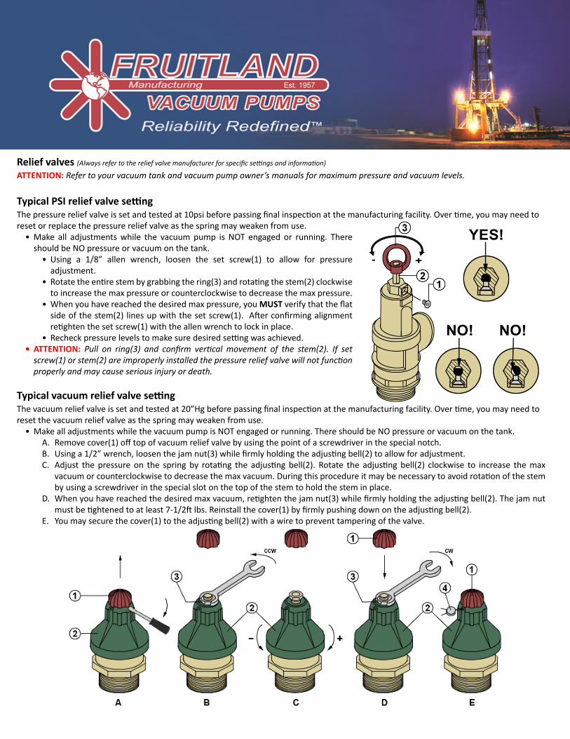
Typical PSI relief valve settingThe pressure relief valve is set and tested at 10psi before passing final inspection at the manufacturing facility. Over time, you may need to reset or replace the pressure relief valve as the spring may weaken from use.
• Make all adjustments while the vacuum pump is NOT engaged or running. There should be NO pressure or vacuum on the tank.
• Using a 1/8” allen wrench, loosen the set screw(1) to allow for pressure adjustment.
• Rotate the entire stem by grabbing the ring(3) and rotating the stem(2) clockwise to increase the max pressure or counterclockwise to decrease the max pressure.
• When you have reached the desired max pressure, you MUST verify that the flat side of the stem(2) lines up with the set screw(1). After confirming alignment retighten the set screw(1) with the allen wrench to lock in place.
• Recheck pressure levels to make sure desired setting was achieved.• ATTENTION: Pull on ring(3) and confirm vertical movement of the stem(2). If set
screw(1) or stem(2) are improperly installed the pressure relief valve will not function properly and may cause serious injury or death.
Typical vacuum relief valve settingThe vacuum relief valve is set and tested at 20”Hg before passing final inspection at the manufacturing facility. Over time, you may need to reset the vacuum relief valve as the spring may weaken from use.
• Make all adjustments while the vacuum pump is NOT engaged or running. There should be NO pressure or vacuum on the tank.A. Remove cover(1) off top of vacuum relief valve by using the point of a screwdriver in the special notch.B. Using a 1/2” wrench, loosen the jam nut(3) while firmly holding the adjusting bell(2) to allow for adjustment.C. Adjust the pressure on the spring by rotating the adjusting bell(2). Rotate the adjusting bell(2) clockwise to increase the max
vacuum or counterclockwise to decrease the max vacuum. During this procedure it may be necessary to avoid rotation of the stem by using a screwdriver in the special slot on the top of the stem to hold the stem in place.
D. When you have reached the desired max vacuum, retighten the jam nut(3) while firmly holding the adjusting bell(2). The jam nut must be tightened to at least 7-1/2ft lbs. Reinstall the cover(1) by firmly pushing down on the adjusting bell(2).
E. You may secure the cover(1) to the adjusting bell(2) with a wire to prevent tampering of the valve.
Recommended