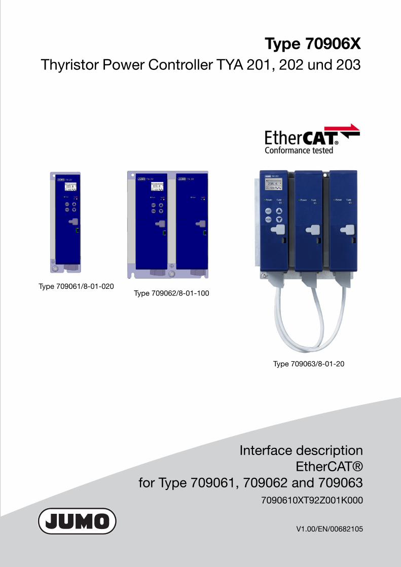
Type 70906XThyristor Power Controller TYA 201, 202 und 203
Interface description EtherCAT®
for Type 709061, 709062 and 7090637090610XT92Z001K000
V1.00/EN/00682105
Type 709061/8-01-020
Type 709063/8-01-20
Type 709062/8-01-100


Table of contents
1 General information.....................................................................5
1.1 Brands ......................................................................................................... 5
1.2 Meaning of the LEDs ................................................................................. 5
2 TwinCAT®.....................................................................................7
2.1 System requirements for the installation of TwinCAT® ......................... 7
2.2 Startup of the TYA 20X .............................................................................. 7
2.3 Adding a device .......................................................................................... 8
2.4 Process data .............................................................................................. 8
2.4.1 Sync Manager (SM) ............................................................................................. 8
2.4.2 Manual PDO allocation ........................................................................................ 9
2.5 Object Description and Configuration ................................................... 14
3 Address tables ...........................................................................15
3.1 Device, Hardware and Software ............................................................. 15
3.2 0x1018 Identity ......................................................................................... 15
3.3 0x2001 Device data .................................................................................. 15
3.4 0x2002 Power controller .......................................................................... 16
3.5 0x2003 Analog input ................................................................................ 17
3.6 0x2004 Setpoint value configuration ...................................................... 17
3.7 0x2005 Monitoring ................................................................................... 18
3.8 0x2006 Digital input ................................................................................. 19
3.9 0x2007 Digital output ............................................................................... 20
3.10 0x2008 Analog output .............................................................................. 20
3.11 0x2009 Modbus ........................................................................................ 20
3.12 0x200A Profibus ...................................................................................... 21
3.13 0x200B Customized parameters ............................................................ 21
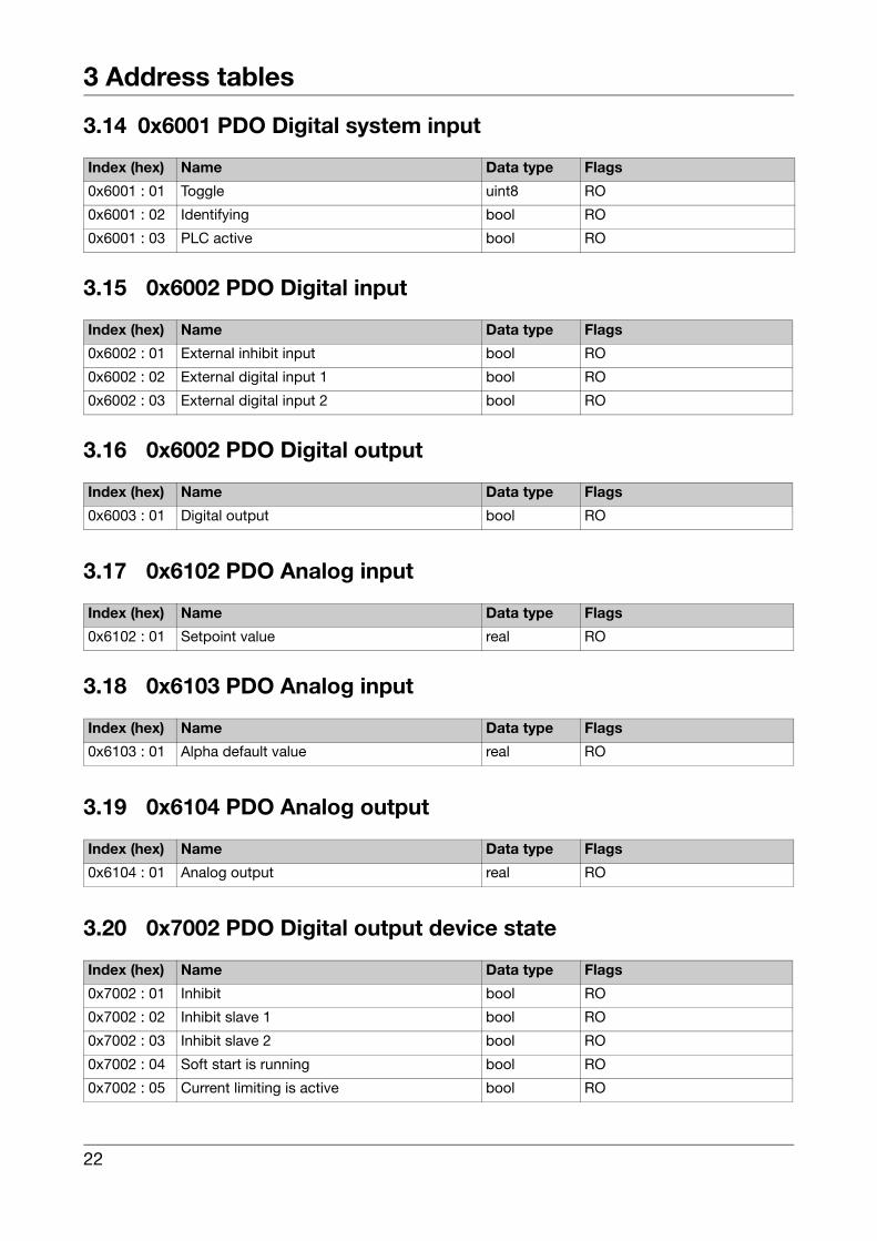
3.14 0x6001 PDO Digital system input ........................................................... 22
3.15 0x6002 PDO Digital input ......................................................................... 22
3.16 0x6002 PDO Digital output ...................................................................... 22
3

Table of contents
3.17 0x6102 PDO Analog input ........................................................................ 22
3.18 0x6103 PDO Analog input ........................................................................ 22
3.19 0x6104 PDO Analog output ..................................................................... 22
3.20 0x7002 PDO Digital output device state ................................................ 22
3.21 0x7003 PDO Digital output master ......................................................... 23
3.22 0x7004 PDO Digital output slave 1 ......................................................... 23
3.23 0x7005 PDO Digital output slave 2 ......................................................... 24
3.24 0x7006 PDO Digital output master slave ............................................... 24
3.25 0x7007 PDO Digital output hardware ..................................................... 24
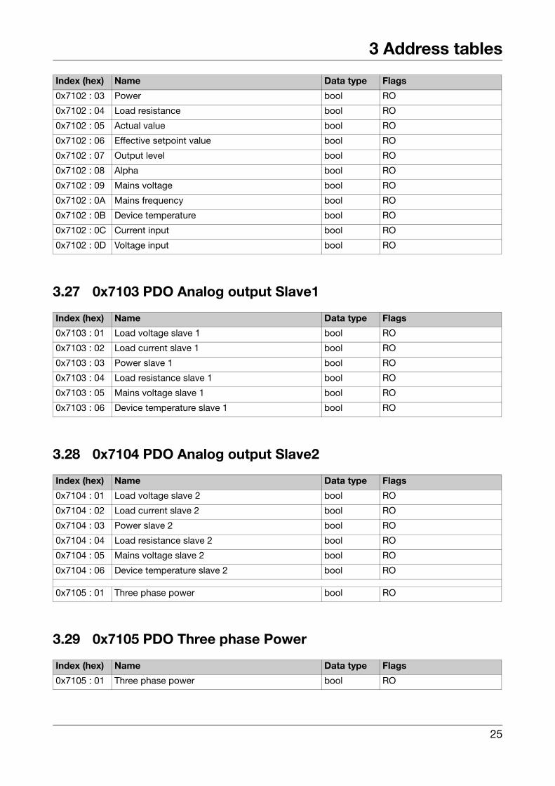
3.26 0x7102 PDO Analog output Master ........................................................ 24
3.27 0x7103 PDO Analog output Slave1 ......................................................... 25
3.28 0x7104 PDO Analog output Slave2 ......................................................... 25
3.29 0x7105 PDO Three phase Power ............................................................ 25
4

1 General information
1.1 BrandsEtherCAT® is a registered trademark and patented technology licensedby Beckhoff Automation GmbH, Germany.
TwinCAT® is a registered and licensed trademark of Beckhoff Automa-tion GmbH.
1.2 Meaning of the LEDs
LED Meaning
RUN OFF INIT: Initialization phase, no communication
Flashing PREOP: Mailbox communication running; no process data traffic possible.
Short flash SAFEOP: Check the channels of the sync manager; out-puts are in safe state
ON OP: normal operating status; mailbox and process data communication running
SPEED ON Indicates a 100 MBit connection
LINK / ACTIVITY ON Connected
Flickering Data being transferred
OFF Not connected
RUN
(Bus IN)
(Bus OUT)
SPEED
LINK / ACTIVITY
SPEED
LINK / ACTIVITY
5

1 General information
6

2 TwinCAT®
TwinCAT® is an open PC software solution for real-time control withPLC, NC axis control, programming, and operation.
For further information and installation instructions go to:https://infosys.beckhoff.com/
2.1 System requirements for the installation of TwinCAT®Please note that the TwinCAT 2.x cannot be installed on a 64-bit versionof Windows.
2.2 Startup of the TYA 20XIn order to create the configuration in offline and online mode, the Twin-CAT® EtherCAT® master/system manager requires the device descrip-tion file for the thyristor controller TYA 200. This device description isthe ESI (EtherCAT Slave Information) in the form of an XML file.
The ESI file must be stored in the installation directory of TwinCAT®.
Default setting for TwinCAT 2: C:\TwinCAT\Io\EtherCAT
Start Launch the TwinCAT® system manager from the program group or thequick-start bar.
The start takes slightly longer if the ESI files in the installation directoryhave changed since the last time the system manager was started.
The following window is displayed after the system manager is started:
7

2 TwinCAT®
2.3 Adding a deviceFor precise and detailed instructions about how to create offline andonline configurations go to:https://infosys.beckhoff.com
2.4 Process dataThe process data overview lists the detailed PDO selection.These specifications are not usually necessary for operation underTwinCAT® because it can easily be configured from the configurationinterface using the process data preselection.
2.4.1 Sync Manager (SM)
The TYA provides multiple different process data objects (PDO) for inputand output data. They can be activated or deactivated in the systemmanager for cyclic process data transfer.
8

2 TwinCAT®
2.4.2 Manual PDO allocation
The desired Sync Manager is selected in the top left field "Sync Manag-er" in order to configure the process data ("Inputs" or "Outputs") In thefield below, "PDO allocation", the allocated process data can then beactivated or deactivated for the selected SM.
The EtherCAT® system then needs to be restarted ("Actions" menu ->"Reload the configuration"). This restarts the EtherCAT® communica-tion and the process data are transferred from the device.
9

2 TwinCAT®
Table 1 Process data SM2 tab (Outputs)
Index Size (Byte.Bit)
Name PDO contents
1600 5.3 DO System Index 0x6001:01 - ToggleIndex 0x6001:02 - IndentifyingIndex 0x6001:03 - PLC active
v Chapter 3.14 "0x6001 PDO Digital system input"
1601 0.3 DO External Inputs Index 0x6002:01 - External inhibit inputIndex 0x6002:02 - External digital input 1Index 0x6002:03 - External digital input 2
1602 7.5 DO Index 0x6003:01 - Digital output1603 4.0 AO System
1604 4.0 AO Setpoint Value Index 0x6102:01 - Setpoint value
1605 4.0 AO Alpha Index 0x6103:01 - Alpha default value
1606 108.0 AO Index 0x6104:01 - Analog output
10

2 TwinCAT®
Table 2 Process data SM3 tab (Inputs)
Index Size (Byte.Bit)
Name PDO contents
1A01 2.0 DI Device Status Index 7002:01 – InhibitIndex 7002:02 – Inhibit Slave 1Index 7002:03 – Inhibit Slave 2Index 7002:04 – Soft start is runningIndex 7002:05 – Current limiting is activeIndex 7002:06 – Ext. change-over to phase angle op.Index 7002:07 – Ext. current limit value is usedIndex 7002:08 – ReconfigurationIndex 7002:09 – Manual modeIndex 7002:0A – Keyboard lockedIndex 7002:0B – Display lighting offIndex 7002:0C – Rotary field detection was passedIndex 7002:0D – Resistance limitation is activeIndex 7002:0E – Ext. change-over of setpoint input
v Chapter 3.20 "0x7002 PDO Digital output devicestate"
1A02 2.0 DI Faults Master Index 7003:01 – Collective faultIndex 7003:02 – Min alarmIndex 7003:03 – Max alarmIndex 7003:04 – Load errorIndex 7003:05 – Teach-in is missingIndex 7003:06 – Blown fuseIndex 7003:07 – Thyristor breakageIndex 7003:08 – Thyristor short circuitIndex 7003:09 – Power limitation due to excessive temp.Index 7003:0A – Excessive temperatureIndex 7003:0B – Mains voltage too lowIndex 7003:0C – Mains voltage too highIndex 7003:0D – Temporary mains voltage dropIndex 7003:0E – Wire break in current inputIndex 7003:0F – Wire break in voltage inputIndex 7003:10 – Bus error
v Chapter 3.21 "0x7003 PDO Digital output master"
1A03 2.0 DI Faults Slave 1 Index 7004:01 – Min alarmIndex 7004:02 – Max alarmIndex 7004:03 – Load errorIndex 7004:04 – Blown fuseIndex 7004:05 – Thyristor breakageIndex 7004:06 – Thyristor short circuitIndex 7004:07 – Power Limitation due to excessive temp.Index 7004:08 – Excessive temperatureIndex 7004:09 – Mains voltage too lowIndex 7004:0A – Mains voltage too highIndex 7004:0B – Temporary mains voltage drop
v Chapter 3.22 "0x7004 PDO Digital output slave 1"
11

2 TwinCAT®
1A04 2.0 DI Faults Slave 2 Index 7005:01 – Min alarmIndex 7005:02 – Max alarmIndex 7005:03 – Load errorIndex 7005:04 – Blown fuseIndex 7005:05 – Thyristor breakageIndex 7005:06 – Thyristor short circuitIndex 7005:07 – Power Limitation due to excessive temp.Index 7005:08 – Excessive temperatureIndex 7005:09 – Mains voltage too lowIndex 7005:0a – Mains voltage too highIndex 7005:0B – Temporary mains voltage drop
v Chapter 3.23 "0x7005 PDO Digital output slave 2"
1A05 2.0 DI Faults Master/Slave Index 7006:01 – Master slave synchronization failedIndex 7006:02 – Error in master slave communicationIndex 7006:03 – Data cable faultyIndex 7006:04 – Rotation field detection failedIndex 7006:05 – Rotation field errorIndex 7006:06 – Wiring error
v Chapter 3.24 "0x7006 PDO Digital output masterslave"
1A06 2.0 DI Hardware in/out Index 7007:01 – Inhibit inputIndex 7007:02 – Digital input 1Index 7007:03 – Digital input 2Index 7007:04 – Digital output
Chapter 3.25 "0x7007 PDO Digital output hardware"
1A07 8.0 Al System
1A08 52.0 AI Measured Values Master
Index 7102:01 – Load voltageIndex 7102:02 – Load currentIndex 7102:03 – PowerIndex 7102:04 – Load resistanceIndex 7102:05 – Actual valueIndex 7102:06 – Effective setpoint valueIndex 7102:07 – Output levelIndex 7102:08 – AlphaIndex 7102:09 – Mains voltageIndex 7102:0A – Mains frequencyIndex 7102:0B – Device temperatureIndex 7102:0C – Current inputIndex 7102:0D – Voltage input
Chapter 3.26 "0x7102 PDO Analog output Master"
1A09 24.0 AI Measured Values Slave1
Index 7103:01 – Load voltageIndex 7103:02 – Load currentIndex 7103:03 – Power slaveIndex 7103:04 – Load resistanceIndex 7103:05 – Mains voltageIndex 7103:06 – Device temperature
v Chapter 3.27 "0x7103 PDO Analog output Slave1"
Index Size (Byte.Bit)
Name PDO contents
12

2 TwinCAT®
1A0A 24.0 AI Measured Values Slave2
Index 7104:01 – Load voltageIndex 7104:02 – Load currentIndex 7104:03 – Power slaveIndex 7104:04 – Load resistanceIndex 7104:05 – Mains voltageIndex 7104:06 – Device temperature
v Chapter 3.28 "0x7104 PDO Analog output Slave2"
1A0B 16.0 AI Measured Values Three Phases
Index 7105:01 – Three phase power
v Chapter 3.29 "0x7105 PDO Three phase Power"
Index Size (Byte.Bit)
Name PDO contents
13

2 TwinCAT®
2.5 Object Description and Configuration
CoE – Online The configuration can be performed via the "CoE – Online" tab.
Extended The online PDO information can be extracted from the device via the[Extended...] button.
14

3 Address tables
3.1 Device, Hardware and Software
3.2 0x1018 Identity
3.3 0x2001 Device data
Index (hex) Name Default
0x1008 : 0 Manufacturer Device Name TYA 200
0x1009 : 0 Manufacturer Hardware Version 358.01.01
0x100a : 0 Manufacturer Software Version 256.02.01
Index (hex) Name Default
0x1018 : 1 Vendor id 0x126
0x1018 : 2 Product code 0xad1C4
0x1018 : 3 Revision number 0x27112D
0x1018 : 4 Serial number 0x0
Index (hex) Name Data type Value range JUMO ID
0x2001 : 1 Size of an instance
0x2001 : 2 Language assistant enum 0: No1: Yes
1.0.0.0
0x2001 : 3 Language enum 0: German1: English2: French3: 4th language
1.0.1.0
0x2001 : 4 Temperature unit enum 0: °C1: °F
1.0.2.0
0x2001 : 5 Switch off display uint16 0... 1440 min 1.0.3.0
0x2001 : 6 Code manual mode uint16 0...9999 1.0.4.0
0x2001 : 7 Code operation level uint16 0...9999 1.0.5.0
0x2001 : 8 Code configuration level uint16 0...9999 1.0.6.0
15

3 Address tables
3.4 0x2002 Power controller
Index (hex) Name Data type Value range JUMO ID
0x2002 : 1 Size of an instance
0x2002 : 2 Mains switching variant enum 0: Single-phase m1: Free-run.eco.cir 2: Eco.Circ. Master3: Eco.Circ. Slave4: 3-phase master5: 3-phase slave 16: 3-phase slave 2
2.0.0.0
0x2002 : 3 Three-phase load wiring enum 0: Y without N-wire1: Y with N-wire2: Delta connection3: Open delta conn.
2.0.1.0
0x2002 : 4 Thyristor control enum 0: Contin.(contr.)1: Logic (switch)
2.0.2.0
0x2002 : 5 Operating mode enum 0:Burst firing1: Phase angle2: Half-wave contr.
2.0.3.0
0x2002 : 6 Cycle time enum 0: fixed (500 ms)1: as fast as poss.
2.0.4.0
0x2002 : 7 Min switch on duration enum 0: none1: 3 sine movements
2.0.5.0
0x2002 : 8 Alpha start enum 0: No1: Yes
2.0.6.0
0x2002 : 9 Angle alpha start uint16 0...90 degrees 2.0.7.0
0x2002 : 10 Soft start enum 0: No1: Yes
2.0.8.0
0x2002 : 11 Soft start type enum 0: With phase angle1: W. burst firing
2.0.9.0
0x2002 : 12 Soft start duration uint16 0...65535 2.0.10.0
0x2002 : 13 Current limiting enum 0: No1: Yes
2.0.11.0
0x2002 : 14 Current limit value float 0...275 2.0.12.0
0x2002 : 15 Resistance limiting enum 0: No1: Yes
2.0.13.0
0x2002 : 16 Resistance limit value float 0...999.99 2.0.14.0
0x2002 : 17 Load type enum 0: Resistive load1: Transformer load
2.0.15.0
0x2002 : 18 Dual energy management enum 0: off1: Device12: Device2
2.0.16.0
0x2002 : 19 Subordinated control enum 0: none1: U2
2: U3: I2
4: I5: P
2.0.17.0
16

3 Address tables
3.5 0x2003 Analog input
3.6 0x2004 Setpoint value configuration
Index (hex) Name Data type Value range JUMO ID
0x2003 : 1 Size of an instance
0x2003 : 2 Current measuring range enum 0: switched off (don’t use)1: 0...20mA2: 4...20mA3: 0...10V (don’t use)4: 2...10V (don’t use)5: 0...5V (don’t use)6: 1...5V (don’t use)7: Customer spec.
3.0.0.0
0x2003 : 3 Current range start float 0 to 20 mA 3.0.1.0
0x2003 : 4 Current range end float 0 to 20 mA 3.0.2.0
0x2003 : 5 Voltage measuring range enum 0: switched off (don’t use)1: 0...20mA (don’t use)2: 4...20mA (don’t use)3: 0...10V4: 2...10V5: 0...5V6: 1...5V7: Customer spec.
3.0.3.0
0x2003 : 6 Voltage range start float 0 to 10 V 3.0.4.0
0x2003 : 7 Voltage range end float 0 to 10 V 3.0.5.0
Index (hex) Name Data type Value range JUMO ID
0x2004 : 1 Size of an instance
0x2004 : 2 Setpoint input enum 0: No default value (don’t use)1: Last value (don’t use)2: Current input3: Voltage input4: Value adjustable (don’t use)5: Via interface6: Binary input 17: Binary input 2
4.0.0.0
0x2004 : 3 Alpha input enum 0: No default value1: Last value (don’t use)2: Current input3: Voltage input4: Value adjustable5: Via interface6: Binary input 1 (don’t use)7: Binary input 2 (don’t use)
4.0.1.0
0x2004 : 4 Alpha default value uint16 0...180 Degrees 4.0.2.0
17

3 Address tables
3.7 0x2005 Monitoring
0x2004 : 5 Input during error enum 0: No default value (don’t use)1: Load value2: Current input3: Voltage input4: Value adjustable5: Via interface (don’t use)6: Binary input 1 (don’t use)7: Binary input 2 (don’t use)
4.0.3.0
0x2004 : 6 Input value during error float 0...115 % 4.0.4.0
0x2004 : 7 Maximum SCR output value float 0...115 % 4.0.5.0
0x2004 : 8 Basic load float 0...100 % 4.0.6.0
Index (hex) Name Data type Value range JUMO ID
Index (hex) Name Data type Value range JUMO ID
0x2005 : 1 Size of an instance
0x2005 : 2 Limit value monitoring enum 0: Switched off1: Load voltage2: Load voltage2 (don’t use)3: Load current4: Load current2 (don’t use)5: Power [W]6: Power [kW]7: Load resistance8: Mains voltage9: Device temperat.10: Setpoint (don’t use)11: From interface (don’t use)
5.0.0.0
0x2005 : 3 Min alarm limit value float 0...9999 5.0.1.0
0x2005 : 4 Max alarm limit value float 0...9999 5.0.2.0
0x2005 : 5 Hysteresis limit value float 0...9999 5.0.3.0
0x2005 : 6 Load monitoring enum 0: No load monit1: Under-current2: Over-current
5.0.4.0
0x2005 : 7 Limit value load monitoring float 0...100 5.0.5.0
0x2005 : 8 Teach-In enum 0: manual1: autom. once2: autom. cyclical
5.0.6.0
0x2005 : 9 Load type enum 0: Standard1: IR radiator
5.0.7.0
0x2005 : 10 Control loop monitoring enum 0: No1: Yes
5.0.8.0
0x2005 : 11 Mains voltage drop monitoring enum 0: No1: Yes
5.0.9.0
18

3 Address tables
3.8 0x2006 Digital input
Index (hex) Name Data type Value range JUMO ID
0x2006 : 1 Size of an instance
0x2006 : 2 Ext. change-over to phase angle op. enum 0: Switched off1: Binary input 12: Binary input 23: Ext. bin.input 14: Ext. bin.input 2
6.0.0.0
0x2006 : 3 Ext. change-over of setpoint input enum 0: Switched off1: Binary input 12: Binary input 23: Ext. bin.input 14: Ext. bin.input 2
6.0.1.0
0x2006 : 4 Setpoint input at change-over enum 0: No default value (don’t use) 1: Last value (don’t use)2: Current input3: Voltage input4: Value adjustable5: Via interface (don’t use)6: Binary input 1 (don’t use)7: Binary input 2 (don’t use)
6.0.2.0
0x2006 : 5 Setpoint value at change-over float 0...115 % 6.0.3.0
0x2006 : 6 Ext. current limiting enum 0: Switched off1: Binary input 12: Binary input 23: Ext. bin.input 14: Ext. bin.input 2
6.0.4.0
0x2006 : 7 Ext. current limit value float 0...275 6.0.5.0
0x2006 : 8 Ext. change-over load monitoring enum 0: Switched off1: Binary input 12: Binary input 23: Ext. bin.input 14: Ext. bin.input 2
6.0.6.0
0x2006 : 9 Limit value load monitoring float 0...100 % 6.0.7.0
0x2006 : 10 Keyboard lock enum 0: Switched off1: Binary input 12: Binary input 23: Ext. bin.input 14: Ext. bin.input 2
6.0.8.0
0x2006 : 11 Ext. deactivation of display lighting enum 0: Switched off1: Binary input 12: Binary input 23: Ext. bin.input 14: Ext. bin.input 2
6.0.9.0
0x2006 : 12 Control direction inhibit input enum 0: open - Load OFF1: open - Load ON
6.0.10.0
0x2006 : 13 Control direction digital input 1 enum 0: open active1: open inactive
6.0.11.0
0x2006 : 14 Control direction digital input 2 enum 0: open active1: open inactive
6.0.12.0
19

3 Address tables
3.9 0x2007 Digital output
3.10 0x2008 Analog output
3.11 0x2009 Modbus
Index (hex) Name Data type Value range JUMO ID
0x2007 : 1 Size of an instance
0x2007 : 2 Output mode enum 0: Fault alrm. outp1: Energy meter2: Interf.sign.outp
7.0.0.0
0x2007 : 3 Control direction digital output enum 0: Normally open1: Normally closed
7.0.1.0
0x2007 : 4 Pulses per kWh uint16 1...1000 7.0.2.0
0x2007 : 5 Pulse length uint16 30...2000 ms 7.0.3.0
0x2007 : 6 Min. pulse pause uint16 30...2000 ms 7.0.4.0
Index (hex) Name Data type Value range JUMO ID
0x2008 : 1 Size of an instance
0x2008 : 2 Signal type enum 0: switched off1: 0...20mA2: 4...20mA3: 0...10V 4: 2...10V 5: 0...5V 6: 1...5V 7: Customer spec. (don’t use)
8.0.0.0
0x2008 : 3 Value to be output enum 0: Switched off (don’t use)1: Load voltage2: Load voltage2
3: Load current4: Load current25: Power [W]6: Power [kW]7: Load resistance8: Mains voltage9: Device temperat.10: Setpoint11: From interface
8.0.1.0
0x2008 : 4 Signal range start value float 0.0...9999.9 8.0.2.0
0x2008 : 5 Signal range end value float 0.0...9999.9 8.0.3.0
Index (hex) Name Data type Value range JUMO ID
0x2009 : 1 Size of an instance
0x2009 : 2 Baud rate enum 0: 9600 baud1: 19200 baud2: 38400 baud3: 115200 baud
9.0.0.0
20

3 Address tables
3.12 0x200A Profibus
3.13 0x200B Customized parameters
0x2009 : 3 Data format enum 0: 8-1-none1: 8-1-odd2: 8-1-even3: 8-2-none
9.0.1.0
0x2009 : 4 Device address uint16 0...255 9.0.2.0
0x2009 : 5 Min. response time uint16 0...500 ms 9.0.3.0
Index (hex) Name Data type Value range JUMO ID
Index (hex) Name Data type Value range JUMO ID
0x200a : 1 Size of an instance
0x200a : 2 Device address uint16 0...125 10.0.0.0
0x200a : 3 Data format enum 0: Motorola1: Intel
10.0.1.0
Index (hex) Name Data type Value range JUMO ID
0x200b : 1 Size of an instance
0x200b : 2 Customized parameter 1 uint16 0...65535 11.0.0.0
0x200b : 3 Customized parameter 2 uint16 0...65535 11.0.1.0
0x200b : 4 Customized parameter 3 uint16 0...65535 11.0.2.0
. . uint16 0...65535 .
. . uint16 0...65535 .
. . uint16 0...65535 .
0x200b : 91 Customized parameter 90 uint16 0...65535 11.0.89.0
21
3 Address tables
3.14 0x6001 PDO Digital system input
3.15 0x6002 PDO Digital input
3.16 0x6002 PDO Digital output
3.17 0x6102 PDO Analog input
3.18 0x6103 PDO Analog input
3.19 0x6104 PDO Analog output
3.20 0x7002 PDO Digital output device state
Index (hex) Name Data type Flags
0x6001 : 01 Toggle uint8 RO
0x6001 : 02 Identifying bool RO
0x6001 : 03 PLC active bool RO
Index (hex) Name Data type Flags
0x6002 : 01 External inhibit input bool RO
0x6002 : 02 External digital input 1 bool RO
0x6002 : 03 External digital input 2 bool RO
Index (hex) Name Data type Flags
0x6003 : 01 Digital output bool RO
Index (hex) Name Data type Flags
0x6102 : 01 Setpoint value real RO
Index (hex) Name Data type Flags
0x6103 : 01 Alpha default value real RO
Index (hex) Name Data type Flags
0x6104 : 01 Analog output real RO
Index (hex) Name Data type Flags
0x7002 : 01 Inhibit bool RO
0x7002 : 02 Inhibit slave 1 bool RO
0x7002 : 03 Inhibit slave 2 bool RO
0x7002 : 04 Soft start is running bool RO
0x7002 : 05 Current limiting is active bool RO
22

3 Address tables
3.21 0x7003 PDO Digital output master
3.22 0x7004 PDO Digital output slave 1
0x7002 : 06 Ext. change-over to phase angle op. bool RO
0x7002 : 07 Ext. current limit value is used bool RO
0x7002 : 08 Reconfiguration bool RO
0x7002 : 09 Manual mode bool RO
0x7002 : 0A Keyboard locked bool RO
0x7002 : 0B Display lighting off bool RO
0x7002 : 0C Rotary field detection was passed bool RO
0x7002 : 0D Resistance limitation is active bool RO
0x7002 : 0E Ext. change-over of setpoint input bool RO
Index (hex) Name Data type Flags
Index (hex) Name Data type Flags
0x7003 : 01 Collective fault bool RO
0x7003 : 02 Min alarm bool RO
0x7003 : 03 Max alarm bool RO
0x7003 : 04 Load error bool RO
0x7003 : 05 Teach-in is missing bool RO
0x7003 : 06 Blown fuse bool RO
0x7003 : 07 Thyristor breakage bool RO
0x7003 : 08 Thyristor short circuit bool RO
0x7003 : 09 Power limitation due to excessive temp. bool RO
0x7003 : 0A Excessive temperature bool RO
0x7003 : 0B Mains voltage too low bool RO
0x7003 : 0C Mains voltage too high bool RO
0x7003 : 0D Temporary mains voltage drop bool RO
0x7003 : 0E Wire break in current input bool RO
0x7003 : 0F Wire break in voltage input bool RO
0x7003 : 10 Bus error bool RO
Index (hex) Name Data type Flags
0x7004 : 01 Min alarm slave 1 bool RO
0x7004 : 02 Max alarm slave 1 bool RO
0x7004 : 03 Load error slave 1 bool RO
0x7004 : 04 Blown fuse slave 1 bool RO
0x7004 : 05 Thyristor breakage slave 1 bool RO
0x7004 : 06 Thyristor short circuit slave 1 bool RO
0x7004 : 07 Power Limitation due to excessive temp. slave 1 bool RO
0x7004 : 08 Excessive temperature slave 1 bool RO
23

3 Address tables
3.23 0x7005 PDO Digital output slave 2
3.24 0x7006 PDO Digital output master slave
3.25 0x7007 PDO Digital output hardware
3.26 0x7102 PDO Analog output Master
0x7004 : 09 Mains voltage too low slave 1 bool RO
0x7004 : 0A Mains voltage too high slave 1 bool RO
0x7004 : 0B Temporary mains voltage drop slave 1 bool RO
Index (hex) Name Data type Flags
Index (hex) Name Data type Flags
0x7005 : 01 Min alarm slave 2 bool RO
0x7005 : 02 Max alarm slave 2 bool RO
0x7005 : 03 Load alarm slave 2 bool RO
0x7005 : 04 Blown fuse slave 2 bool RO
0x7005 : 05 Thyristor breakage slave 2 bool RO
0x7005 : 06 Thyristor short circuit slave 2 bool RO
0x7005 : 07 Power Limitation due to excessive temp. slave 2 bool RO
0x7005 : 08 Excessive temperature slave 2 bool RO
0x7005 : 09 Mains voltage too low slave 2 bool RO
0x7005 : 0A Mains voltage too high slave 2 bool RO
0x7005 : 0B Temporary mains voltage drop slave 2 bool RO
Index (hex) Name Data type Flags
0x7006 : 01 Master slave synchronization failed bool RO
0x7006 : 02 Error in master slave communication bool RO
0x7006 : 03 Data cable faulty bool RO
0x7006 : 04 Rotation field detection failed bool RO
0x7006 : 05 Rotation field error bool RO
0x7006 : 06 Wiring error bool RO
Index (hex) Name Data type Flags
0x7007 : 01 Inhibit input bool RO
0x7007 : 02 Digital input 1 bool RO
0x7007 : 03 Digital input 2 bool RO
0x7007 : 04 Digital output bool RO
Index (hex) Name Data type Flags
0x7102 : 01 Load voltage bool RO
0x7102 : 02 Load current bool RO
24
3 Address tables
3.27 0x7103 PDO Analog output Slave1
3.28 0x7104 PDO Analog output Slave2
3.29 0x7105 PDO Three phase Power
0x7102 : 03 Power bool RO
0x7102 : 04 Load resistance bool RO
0x7102 : 05 Actual value bool RO
0x7102 : 06 Effective setpoint value bool RO
0x7102 : 07 Output level bool RO
0x7102 : 08 Alpha bool RO
0x7102 : 09 Mains voltage bool RO
0x7102 : 0A Mains frequency bool RO
0x7102 : 0B Device temperature bool RO
0x7102 : 0C Current input bool RO
0x7102 : 0D Voltage input bool RO
Index (hex) Name Data type Flags
Index (hex) Name Data type Flags
0x7103 : 01 Load voltage slave 1 bool RO
0x7103 : 02 Load current slave 1 bool RO
0x7103 : 03 Power slave 1 bool RO
0x7103 : 04 Load resistance slave 1 bool RO
0x7103 : 05 Mains voltage slave 1 bool RO
0x7103 : 06 Device temperature slave 1 bool RO
Index (hex) Name Data type Flags
0x7104 : 01 Load voltage slave 2 bool RO
0x7104 : 02 Load current slave 2 bool RO
0x7104 : 03 Power slave 2 bool RO
0x7104 : 04 Load resistance slave 2 bool RO
0x7104 : 05 Mains voltage slave 2 bool RO
0x7104 : 06 Device temperature slave 2 bool RO
0x7105 : 01 Three phase power bool RO
Index (hex) Name Data type Flags
0x7105 : 01 Three phase power bool RO
25

3 Address tables
26


JUMO GmbH & Co. KG JUMO Instrument Co. Ltd. JUMO Process Control, Inc.Street address:Moritz-Juchheim-Straße 136039 Fulda, GermanyDelivery address:Mackenrodtstraße 1436039 Fulda, GermanyPostal address:36035 Fulda, GermanyPhone:+49 661 6003-0Fax:+49 661 6003-607Email:[email protected]:www.jumo.net
JUMO HouseTemple Bank, RiverwayHarlow, Essex, CM20 2DY, UKPhone:+44 1279 63 55 33Fax:+44 1279 62 50 29Email:[email protected]:www.jumo.co.uk
6733 Myers RoadEast Syracuse, NY 13057, USA
Phone:+1 315 437 5866Fax:+1 315 437 5860Email:[email protected]:www.jumousa.com
Recommended


![[Type text] [Type text] [Type text] - Sports Industry AUfootyindustry.com/files/2014 Reports/AFL/Richmond... · [Type text] [Type text] [Type text] 1 PRESIDENT’S REPORT Season 2014](https://img.pdfslide.us/doc/110x75/5edd9050ad6a402d6668b14f/type-text-type-text-type-text-sports-industry-reportsaflrichmond.jpg)