7/23/2019 Turbine Ppt.ppt
http://slidepdf.com/reader/full/turbine-pptppt 1/28
TURBINE&
COOLING SYSTEM.
Presented By – AVIJEET PRATAP
07ME12
IET AGRA
7/23/2019 Turbine Ppt.ppt
http://slidepdf.com/reader/full/turbine-pptppt 2/28
DEFINITION
A Turbine is a Form of Engine Requires a suitable
working fluid in order to function- a source of High
Grade Energy and a Sink for ow Grade energy! "hen
a Fluid Flows through the Turbine #$art of Energy%ontent is %ontinuously E&tracted and %on'erted in to
(seful mechanical "ork.
7/23/2019 Turbine Ppt.ppt
http://slidepdf.com/reader/full/turbine-pptppt 3/28
PRICIPLE OF STEAM TURBINE
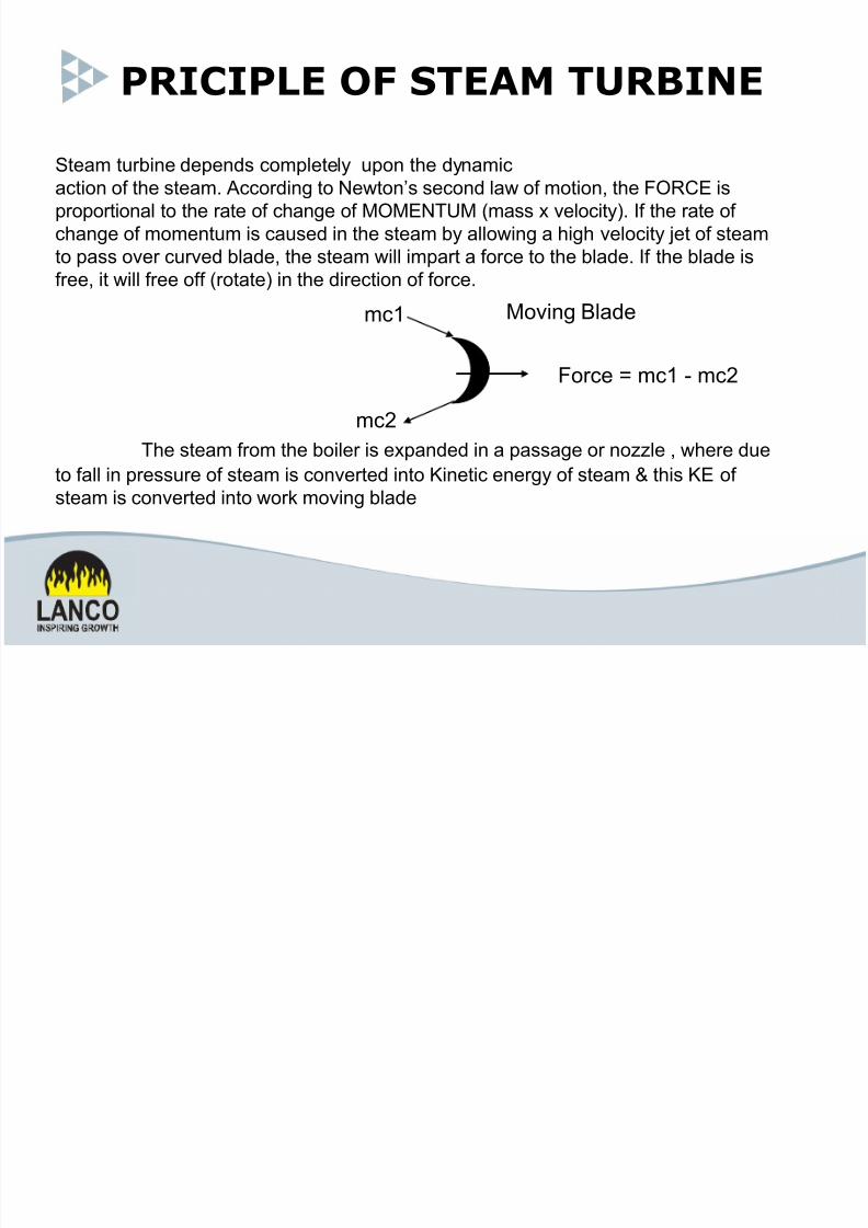
Steam turbine deends !"m#ete#y u"n t$e dynami!
a!ti"n "% t$e steam. A!!"rdin& t" 'e(t"n)s se!"nd #a( "% m"ti"n* t$e +,R-E is
r""rti"na# t" t$e rate "% !$an&e "% M,ME'TM /mass e#"!ity. I% t$e rate "%
!$an&e "% m"mentum is !aused in t$e steam by a##"(in& a $i&$ e#"!ity 3et "% steam
t" ass "er !ured b#ade* t$e steam (i## imart a %"r!e t" t$e b#ade. I% t$e b#ade is
%ree* it (i## %ree "%% /r"tate in t$e dire!ti"n "% %"r!e.
T$e steam %r"m t$e b"i#er is eanded in a assa&e "r n"44#e * ($ere duet" %a## in ressure "% steam is !"nerted int" 5ineti! ener&y "% steam 6 t$is 5E "%
steam is !"nerted int" ("r m"in& b#ade
M"in& B#ade
+"r!e 8 m!1 9 m!2
m!1
m!2
7/23/2019 Turbine Ppt.ppt
http://slidepdf.com/reader/full/turbine-pptppt 4/28
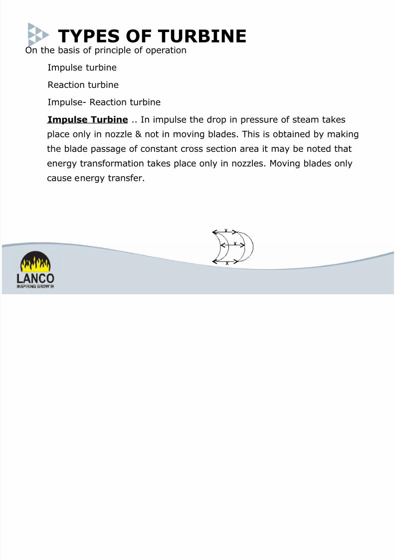
TYPES OF TURBINE)n the basis of *rinci*le of o*eration
+m*ulse turbine
Reaction turbine
+m*ulse- Reaction turbine
Impulse Turbine !! +n im*ulse the dro* in *ressure of steam takes
*lace only in no,,le not in mo'ing blades! This is obtained by makingthe blade *assage of constant cross section area it may be noted that
energy transformation takes *lace only in no,,les! .o'ing blades only
cause energy transfer!
X
X
X
7/23/2019 Turbine Ppt.ppt
http://slidepdf.com/reader/full/turbine-pptppt 5/28
Re!"i#n "urbine/-$ressure dro* take *lace in rotor 0.!1!2! Energy
transformation takes *lace in rotor! Energy transfer only inrotor!
Impulse$ Re!"i#n "urbine/-+n this turbine dro* in *ressure of steam takes
*lace in fi&ed blade as well as mo'ing blade! +t may benoted that energy transformation occur in both fi&ed blade mo'ing blade! The rotor blade cause energy transfer energy transformation!
7/23/2019 Turbine Ppt.ppt
http://slidepdf.com/reader/full/turbine-pptppt 6/28
COMPOUNDING
C#mp#un%in #' Impulse "urbine /-
)ne row of no,,les followed by one row of bladesis called a stage of turbines! %om*ounding is amethod for reducing the rotational s*eed of the
im*ulse turbine to *ractical limit! 1oiler *ressuredown to condenser *ressure in a single stages sohigh R$. large diameter of turbine!
T(ree ")pe #' !#mp#un%in $ressure com*ounding
3elocity com*ounding
$r 'elocity com*ounding
7/23/2019 Turbine Ppt.ppt
http://slidepdf.com/reader/full/turbine-pptppt 7/28
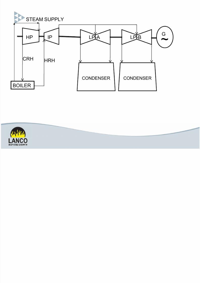
B,I:ER
STEAM SPP:;
-R< <R<
-,'=E'SER -,'=E'SER
><P IP :P9A :P9B G
7/23/2019 Turbine Ppt.ppt
http://slidepdf.com/reader/full/turbine-pptppt 8/28
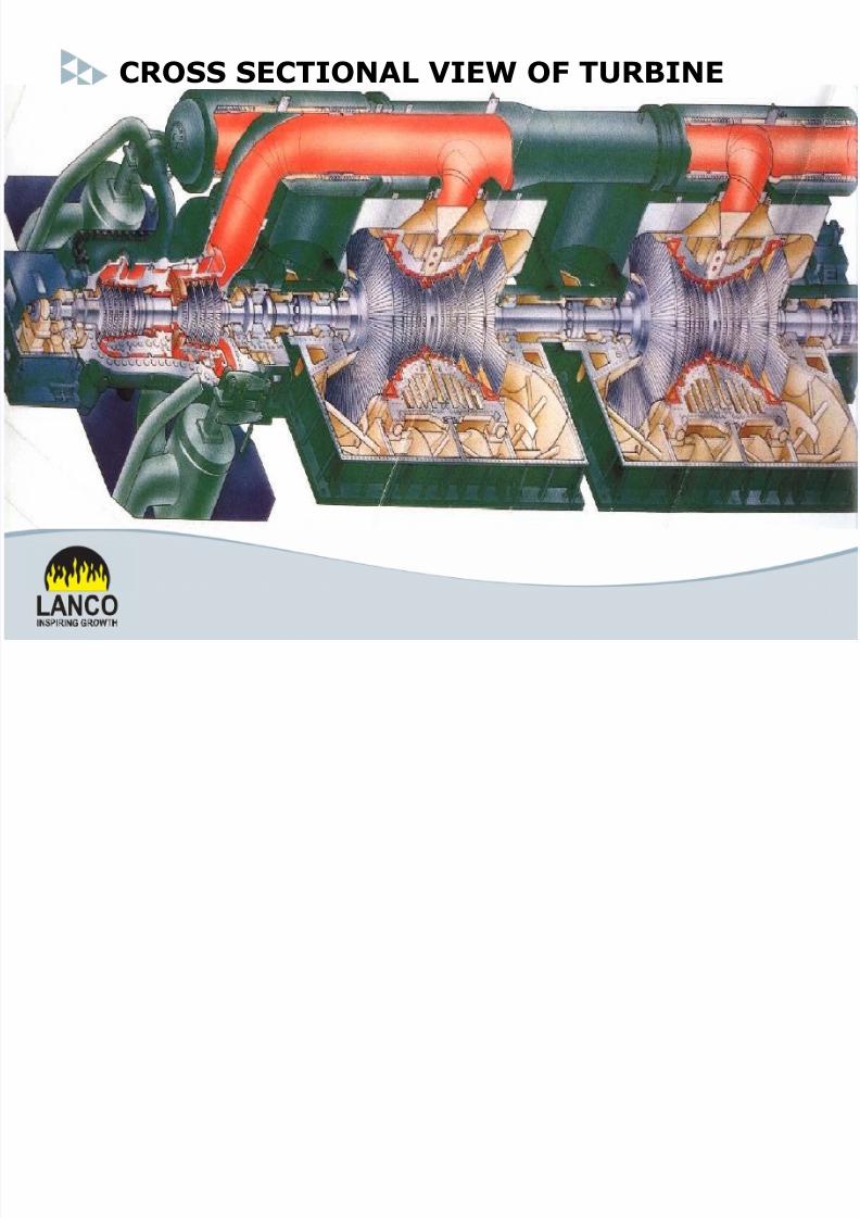
CROSS SECTIONAL *IE+ OF TURBINE

7/23/2019 Turbine Ppt.ppt
http://slidepdf.com/reader/full/turbine-pptppt 9/28
!
COOLING
SYSTEM
7/23/2019 Turbine Ppt.ppt
http://slidepdf.com/reader/full/turbine-pptppt 10/28
CIRCULATING WATER SYSTEM
+4TR)5(%T+)4
! %irculating "ater system su**lies cooling water to the
turbine condenser! !
• +t is used to maintain the 'acuum in the condenser!
7/23/2019 Turbine Ppt.ppt
http://slidepdf.com/reader/full/turbine-pptppt 11/28
Ty*es of %irculating water system
6! )*en or )nce Through
+t is used when there is a large source of water
a'ailable!
e!g!- ri'er # ocean!
7! %losed %ooling system
+n this system# warm water from condenser is*assed through a cooling de'ice# like cooling tower!
7/23/2019 Turbine Ppt.ppt
http://slidepdf.com/reader/full/turbine-pptppt 12/28
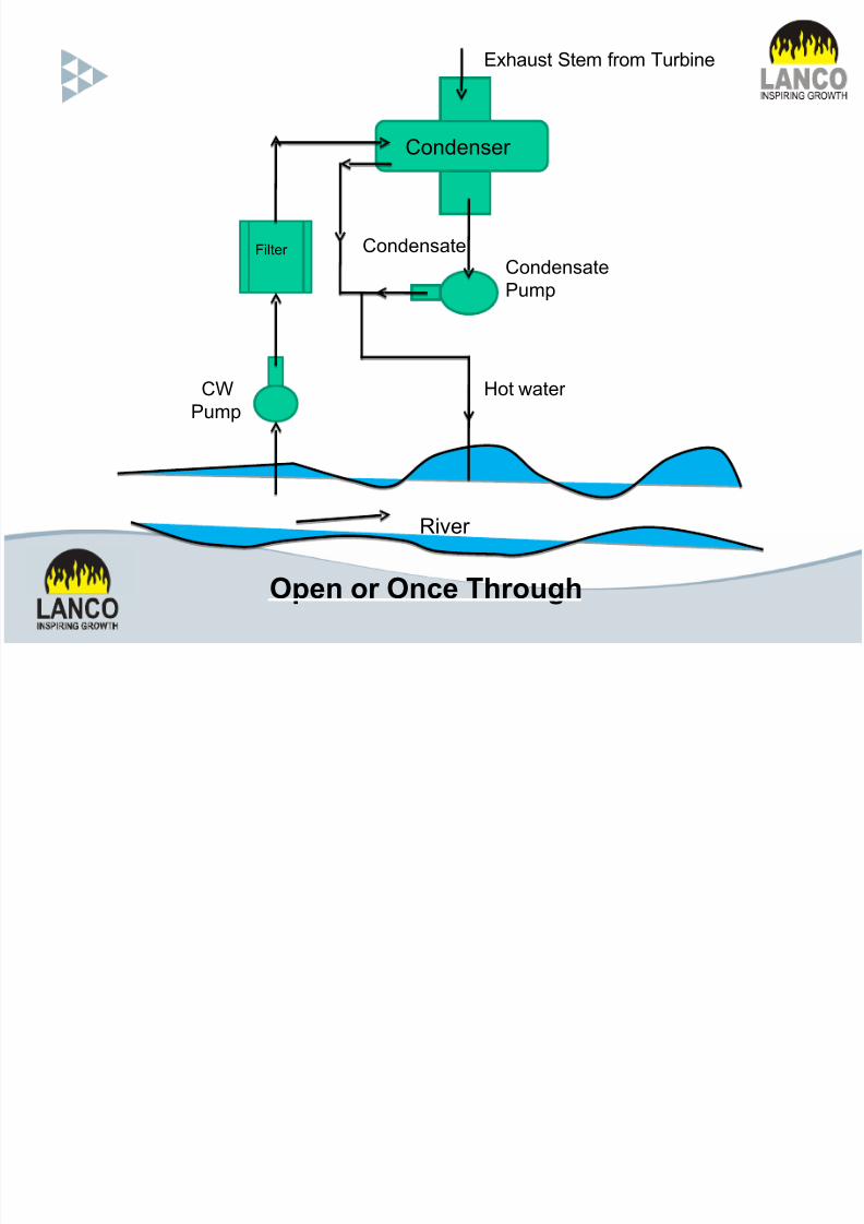
-"ndenser
+i#ter
-?
Pum
-"ndensate
Pum
-"ndensate
<"t (ater
Rier
Open or Once Through
E$aust Stem %r"m Turbine
7/23/2019 Turbine Ppt.ppt
http://slidepdf.com/reader/full/turbine-pptppt 13/28
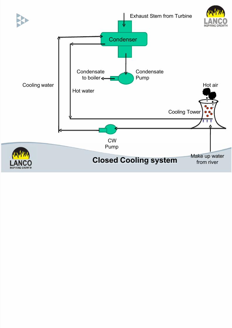
Mae u (ater
%r"m rier
-?
Pum
-"ndensate
Pum
-"ndenser
E$aust Stem %r"m Turbine
-""#in& (ater
-"ndensate
t" b"i#er
<"t air <"t (ater
-""#in& T"(er
Closed Cooling syse!
7/23/2019 Turbine Ppt.ppt
http://slidepdf.com/reader/full/turbine-pptppt 14/28
%ooling tower
• +t cools the warm water discharged from the
condenser feed the cool water back to the
condenser!
• +t reduces the cooling water demand in the *ower
*lant!

7/23/2019 Turbine Ppt.ppt
http://slidepdf.com/reader/full/turbine-pptppt 15/28
Types of cooling tower
6! 4atural 5raught %ooling Tower
7! .echanical 5raught %ooling Tower A! Forced 5raught %ooling Tower
1! +nduced 5raught %ooling Tower
7/23/2019 Turbine Ppt.ppt
http://slidepdf.com/reader/full/turbine-pptppt 16/28
osses in cooling tower
6! E'a*oration osses
7! 5rift osses
8! 1lowdown osses
7/23/2019 Turbine Ppt.ppt
http://slidepdf.com/reader/full/turbine-pptppt 17/28
January @* 201@
LUBE OIL SYSTEM
7/23/2019 Turbine Ppt.ppt
http://slidepdf.com/reader/full/turbine-pptppt 18/28
TURBINE LUBE OIL SYSTEM TURBINE LUBE OIL SYSTEM
1.FLOW DIAGRAM OF LUBE OIL SYSTEM
2.NECESSITY OF LUBE OIL SYSTEM
3.COMPONENTS OF LUBE OIL SYSTEM
4.FUNCTIONS OF INDIVIDUAL
COMPONENTS OIL
5.FLOW TO DIFFERENT BRANCHES
6.FIRE PROTECTIONS
7/23/2019 Turbine Ppt.ppt
http://slidepdf.com/reader/full/turbine-pptppt 19/28
• Lub!"#$!%& ' To supplies oil to the bearing to form a film
of oil as the shaft rotates.
• T()*(#$u( "%&$%+ ' To maintain temperature of the
bearing.
• S(#+!&, )(-!u) ' To the prevent H2 leak out along the
Generator shaft.
• #"/!&, %0 #0$ ' Supply to jacking device.
January @* 201@

7/23/2019 Turbine Ppt.ppt
http://slidepdf.com/reader/full/turbine-pptppt 20/28
COMPONENTS OF LUBE OIL SYSTEM COMPONENTS OF LUBE OIL SYSTEM
T( $() )#!&+ "%&!$ %0 M#!& %!+ *u)* BOP
)#!& %!+ $#&/ AC +ub!"#&$ *u)* DC ()(,(&" %!+
*u)*MSP *!++ #+( %!+ "%%+( T#&0( #+( %!+
)%/( (*##$% #0$ #"/!&, u* -(!"( %!+ -%,(&
(*##$% %!+ +((+ !&-!"#$% # 7(++ # "%&&("$!&, +!&(
)%&!$%!&, !&$u)(&$ ($".
7/23/2019 Turbine Ppt.ppt
http://slidepdf.com/reader/full/turbine-pptppt 21/28
The oil tank adopts a combination mode as variousdevices allocated on the tank as
• AC +ub( %!+ *u)*
• DC ()(,(&" %!+ *u)*• O!+ )%/( (*##$%
• O!+ +((+ !&-!"#$%
• E+("$!" (#$(
• S*!++ #+(• BOP
• MSP
January @* 201@

7/23/2019 Turbine Ppt.ppt
http://slidepdf.com/reader/full/turbine-pptppt 22/28
+4TR)5(%T+)4
Hydrogen is used for the cooling of generator rotor. Hydrogen
is so much explosive when it come into contact with air . Tosave this hydrogen from explosion we need sealing of this
hydrogen. For this purpose we generally use oil. This sealing
is very much similar to sealing of the pump on its gland.
SEA )+ S9STE.
7/23/2019 Turbine Ppt.ppt
http://slidepdf.com/reader/full/turbine-pptppt 23/28
• Providing seal oil to a sealing continuously
• Prevent the escape of hydrogen gas from the generator
at the point of rotor exit . A continuous film between the
rotor collar and seal liner is maintaining by means of oil ata pressure which is slightly above then hydrogen pressure.
The functions of the seal oilcontrol system

7/23/2019 Turbine Ppt.ppt
http://slidepdf.com/reader/full/turbine-pptppt 24/28
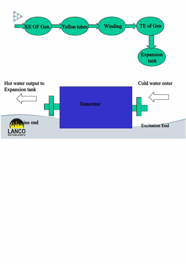
STATOR +ATER COOLING
SYSTEM
F(4%T+)4The Stator %oil %ooling "ater System main function
is to guarantee cooling water uninterru*ted flow
into stator coil! At the same time# the system
also must control enter the stator coil water
*ressure # flow# tem*erature# conducti'ity
7/23/2019 Turbine Ppt.ppt
http://slidepdf.com/reader/full/turbine-pptppt 25/28
System consists of
7 .otor dri'en *um*s#
7 %oolers#
7 Filters and
6 mi&ed 1ed ty*e +on E&changer!
7/23/2019 Turbine Ppt.ppt
http://slidepdf.com/reader/full/turbine-pptppt 26/28
EE ! Gen.EE ! Gen. Teflon tubesTeflon tubes
E"citation EndE"citation End
#old $ater enter #old $ater enter
Turbine endTurbine end
Hot $ater output toHot $ater output to
E"pansion tank E"pansion tank
E"pansionE"pansion
tank tank
%inding%inding TE of GenTE of Gen
Generator Generator

7/23/2019 Turbine Ppt.ppt
http://slidepdf.com/reader/full/turbine-pptppt 27/28

7/23/2019 Turbine Ppt.ppt
http://slidepdf.com/reader/full/turbine-pptppt 28/28
Recommended