Tuning TCP for High Performance in Hybrid Fiber Coaxial Broadband Access Networks
R. Cohen and S. RamanathanBroadband Information Systems Lab
Hewlett-Packard Laboratories1501 Page Mill Road, M/S 1U-17
Palo Alto, CA 94304E-mail: {rcohen,srinivas}@hpl.hp.com
Telephone: (415) 857 4726Fax: (415) 857 8526
Abstract
Motivated by the phenomenal growth of the Internet in recent years, a number of cable operators are in the process ofupgrading their cable networks to offer data services to residential subscribers, providing them direct access to a varietyof community content as well as to the Internet. Using cable modems that implement sophisticated modulation-demodula-tion circuitry, these services promise to offer a several hundred-fold increase in access speeds to the home compared toconventional telephone modems. Initial experiences indicate that cable networks are susceptible to a variety of radio-fre-quency impairments that can result in significant packet loss during data communication. In the face of such losses, theTCP protocol that is predominantly used by data applications degrades dramatically in performance. Consequently, sub-scribers of broadband data services may not perceive the projected hundred fold increase in performance. In this paper,we analyze the performance of TCP under different network conditions using simulations and propose simple modifica-tions that can offer up to three-fold increase in performance in access networks that are prone to losses. These modifica-tions require only minor changes to TCP implementations at the local network servers alone (and not at subscribers’PCs).

1
1 Introduction
The recent phenomenal growth of the Internet has opened up a vast market for high-speed data services to the home. To
pursue this emerging market, a number of telephone carriers and cable operators are actively deploying various broad-
band access technologies including wireline technologies such as Asymmetric Digital Subscriber Line (ADSL) over
telephone copper lines, Hybrid Fiber Coaxial (HFC) technology - a variant of today’s cable networks, and Fiber to the
Curb - an extension of the fiber in the loop concept [6]. Local multipoint distribution alternatives using wireless tech-
nologies operating in the 28 GHz spectrum are also under development. In this paper, we focus on broadband data ser-
vices offered over HFC access networks, which have emerged as a cost-effective technology of choice for many cable
operators and a few telephone carriers.
Using cable modems that employ efficient data modulation schemes, these HFC access networks are capable of trans-
porting tens of Megabits of information per second, thereby offering a several hundred-fold increase in access band-
width compared to conventional telephone modems [6]. However, initial experiences indicate that real-world HFC
networks are susceptible to a variety of radio-frequency impairments that can result in significant packet loss during
data communication [8]. In the face of such losses, the Transmission Control Protocol (TCP), that is predominantly
used by data applications, degrades dramatically in performance. Consequently, subscribers of broadband data services
may not perceive the projected hundred-fold increase in performance.
This paper analyzes the performance of TCP under different HFC network conditions. Based on this analysis, we high-
light architectural considerations and maintenance targets for HFC networks supporting data services. To enhance the
performance of TCP in an HFC network during periods when the network is error prone, various methods of tuning
TCP parameters are proposed. Simulation studies demonstrate that these methods are complementary to one another
and can result in an over three-fold increase in performance under certain loss conditions. A major attractiveness of
these enhancements is that the performance improvements can be obtained by tuning TCP implementations at the HFC
network servers alone, without requiring any changes in subscribers’ PCs.
The rest of this paper is organized as follows. Section 2 outlines the typical architecture of a broadband data system.
Section 3 highlights the performance problems experienced by TCP applications in HFC networks. Using simulations,
Section 4 characterizes the performance of TCP under different network conditions. Various methods for enhancing
TCP performance over HFC networks are discussed in Sections 5 and 6. Section 7 discusses the implications of the
TCP performance results for cable operators deploying broadband data services.
2 Broadband Data Service Architecture
Figure 1 depicts a typical architecture of a broadband data system that services residential subscribers in a metropolitan
area. At the heart of this system is a local Server Complex that houses servers supporting a variety of community ser-
vices including bulletin boards, newsgroups, electronic mail, directory services, Web access, etc., as well as caching
servers to maintain local copies of Web pages that are frequently accessed from the Internet. The servers are intercon-
nected by a high-speed ATM (or FDDI) network. Routers and firewalls enable connectivity from the HFC network to
external networks including the Internet. Data retrieved from the server complex is routed over the HFC network via

2
one or more Signal Conversion Systems (SCSs). To enable data transmissions to coexist with transmission of analog
television signals, data transmissions over the HFC network are analog modulated. Frequency division multiplexing is
used over the HFC network to permit the data channels to operate at different frequencies than analog television chan-
nels. The design of the HFC network forces distinct downstream and upstream channels to be used for communication
to and from the home, respectively. In most deployments, the downstream channels operate in the 450-750 MHz fre-
quency band whereas the upstream channels operate in the 5-40 MHz band.
In a subscriber’s home, access to broadband data services is enabled through a Cable Modem (CM) that connects over a
10BaseT interface to a home PC. The CM contains modulation-demodulation hardware to receive and transmit signals
over the HFC network. In keeping with the current trend on the Internet, where a majority of the traffic is Web access
from various servers, the traffic in the broadband data system is expected to be predominantly retrievals from the server
complex to subscribers’ homes. Many CM implementations themselves are asymmetric, offering up to 30 Mbps for
downstream transmission to subscribers’ homes and 0.5-4 Mbps for upstream transmission from subscribers’ homes to
the server complex.
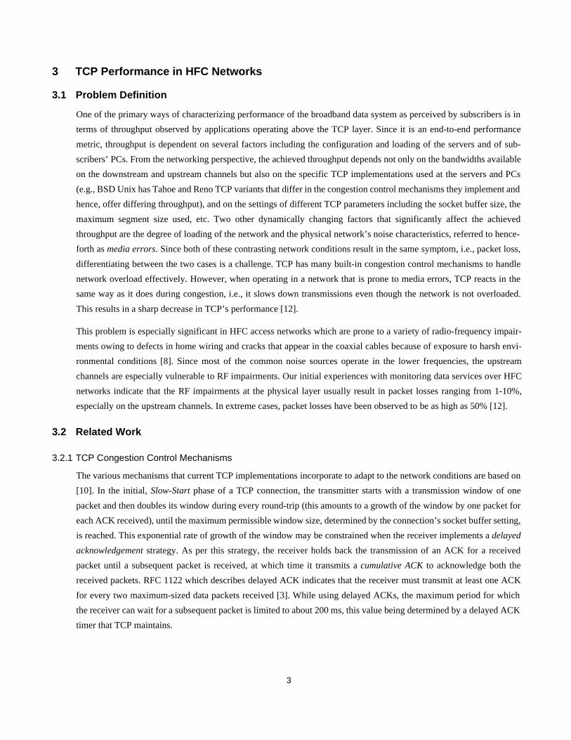
Figure 2 depicts the typical protocol layering in the broadband data system. The client application component executes
on the subscriber’s PC and communicates with server component(s) in the server complex. The standard Internet proto-
col suite (IP/UDP/TCP) is used for communication between subscriber PCs, the server complex, and the Internet. IP
packets are transported over ATM between the server complex and the SCS. For communication over the HFC network,
the IP packets are encapsulated into HFC link packets.
Figure 1. Configuration for providing broadband data services over an HFC network
Signal Conversion System
Cable ModemSubscriber PC
Downstream (10-30 Mbps)
Upstream (0.5-4 Mbps)
Server ComplexConnection to
the Internet
10 Mbps
Router ATM
Hybrid Fiber-Coax
10Base-T
10 Base-T Link
IP
TCP
HTTP, FTP, NNTP,...Application Protocols
Server Complex
ATM HFCLink
IP
Signal Conversion
HFC 10Base-TLinkLink
Cable Modem (CM)
Subscriber PC
Figure 2. Protocol layering in the broadband data system
System (SCS)
Client Applications
ATM Link
IP
TCP
HTTP, FTP, NNTP,...Application Protocols
Server Applications
3
3 TCP Performance in HFC Networks
3.1 Problem Definition
One of the primary ways of characterizing performance of the broadband data system as perceived by subscribers is in
terms of throughput observed by applications operating above the TCP layer. Since it is an end-to-end performance
metric, throughput is dependent on several factors including the configuration and loading of the servers and of sub-
scribers’ PCs. From the networking perspective, the achieved throughput depends not only on the bandwidths available
on the downstream and upstream channels but also on the specific TCP implementations used at the servers and PCs
(e.g., BSD Unix has Tahoe and Reno TCP variants that differ in the congestion control mechanisms they implement and
hence, offer differing throughput), and on the settings of different TCP parameters including the socket buffer size, the
maximum segment size used, etc. Two other dynamically changing factors that significantly affect the achieved
throughput are the degree of loading of the network and the physical network’s noise characteristics, referred to hence-
forth as media errors. Since both of these contrasting network conditions result in the same symptom, i.e., packet loss,
differentiating between the two cases is a challenge. TCP has many built-in congestion control mechanisms to handle
network overload effectively. However, when operating in a network that is prone to media errors, TCP reacts in the
same way as it does during congestion, i.e., it slows down transmissions even though the network is not overloaded.
This results in a sharp decrease in TCP’s performance [12].
This problem is especially significant in HFC access networks which are prone to a variety of radio-frequency impair-
ments owing to defects in home wiring and cracks that appear in the coaxial cables because of exposure to harsh envi-
ronmental conditions [8]. Since most of the common noise sources operate in the lower frequencies, the upstream
channels are especially vulnerable to RF impairments. Our initial experiences with monitoring data services over HFC
networks indicate that the RF impairments at the physical layer usually result in packet losses ranging from 1-10%,
especially on the upstream channels. In extreme cases, packet losses have been observed to be as high as 50% [12].
3.2 Related Work
3.2.1 TCP Congestion Control Mechanisms
The various mechanisms that current TCP implementations incorporate to adapt to the network conditions are based on
[10]. In the initial, Slow-Start phase of a TCP connection, the transmitter starts with a transmission window of one
packet and then doubles its window during every round-trip (this amounts to a growth of the window by one packet for
each ACK received), until the maximum permissible window size, determined by the connection’s socket buffer setting,
is reached. This exponential rate of growth of the window may be constrained when the receiver implements a delayed
acknowledgement strategy. As per this strategy, the receiver holds back the transmission of an ACK for a received
packet until a subsequent packet is received, at which time it transmits a cumulative ACK to acknowledge both the
received packets. RFC 1122 which describes delayed ACK indicates that the receiver must transmit at least one ACK
for every two maximum-sized data packets received [3]. While using delayed ACKs, the maximum period for which
the receiver can wait for a subsequent packet is limited to about 200 ms, this value being determined by a delayed ACK
timer that TCP maintains.

4
To detect packet losses, the transmitter uses the straightforward method of estimating round-trip times of packets. Based
on the transmission times of packets and the arrival times of ACKs, the transmitter maintains an estimate of the maxi-
mum round-trip time over the TCP connection. When an ACK for a packet does not arrive within the maximum round-
trip time (and no ACKs for subsequent packets are received), the transmitter detects the packet loss, retransmits the lost
packet, shrinks its transmission window to one, and reverts back to the Slow-Start phase. The time that the transmitter
spends waiting for an ACK of a lost packet to arrive is referred to as a time-out. Following a time-out, slow-start hap-
pens until the transmission window reaches half the value it had when the time-out occurred. From this point onwards,
the transmitter enters the congestion avoidance mode, growing its window by one packet for every round-trip time. In
this mode, window growth is linear, rather than exponential as in the Slow-Start phase.
While the above strategy is useful when several packets are lost in a transmission window, the TCP transmitter has a
more efficient way to detect and recover from isolated packet losses. Isolated packet losses result in out-of-sequence
packet arrivals at the receiver and trigger the transmission of duplicate ACKs (dupACKs). Upon receiving three
dupACKs, assuming that the packet referred to by the dupACKs has been lost, the transmitter performs fast retransmit
by immediately retransmitting the lost data packet. When the ACK for the retransmitted packet is received, the transmit-
ter performs fast recovery by shrinking its transmission window to half the value of the window at the time when the
packet loss was detected. Then, the transmitter begins to operate in the congestion avoidance mode.
3.2.2 TCP over Lossy Networks
The problems in TCP performance over lossy networks have thus far been addressed mainly in the context of wireless
LANs. Three main approaches have been proposed for such networks:
• Reliable link layer protocols: In this approach, the link layer protocol incorporates retransmission mechanisms to
recover from media errors, thereby masking the effect of media errors from the TCP layer above. Most SCS-CM pro-
tocols being currently used for communication over the HFC network do not guarantee reliable delivery. Incorporat-
ing reliability into these protocols would necessitate changes in the SCS and CM designs. Furthermore, since not all
applications require reliability, a common reliable link protocol cannot be used for all applications. Hence, in this
approach, a more complicated link protocol that adapts to application requirements is necessary.
• “TCP aware” link layer protocols: A typical example in this category is the Snoop protocol [2]. As per this
approach, a base station in a wireless LAN tracks all TCP connections and maintains for each connection a cache of
recently transmitted packets. When the base station notices dupACKs, it retransmits packets locally on the wireless
segment without the original TCP transmitter (that is on a wired network) even being aware of the loss. This
approach is not suitable for large network deployments, in which a wireless base station or an SCS in an HFC net-
work must snoop on all packets that they route and maintain state information for each TCP connection. The result-
ing implementation complexity and performance impact make this approach less suitable for large-scale networks.
• “Split Connection” protocols: In this approach, a TCP connection between the source on a wired network and desti-
nation on a wireless network is transparently split into two transport connections: one for the wired network and
another for the wireless network [1]. The TCP implementation for the wireless network is modified so as to be aware
of handoffs in the wireless network and to initiate slow-start immediately after a handoff. Although initially designed

5
to handle mobility issues, this approach is also useful in handling packet losses that occur in the wireless network
locally [2]. In an HFC network, the split connection approach must be implemented at the SCS, thereby requiring
per connection state information and processing at the SCS.
Many approaches that have been proposed for increasing the performance of TCP during congestion are applicable, to
some extent, in lossy HFC networks. The implementation of selective acknowledgements in TCP to enable the trans-
mitters to more precisely determine packets that are lost and recover from such losses is proposed in [11]. Initial testing
of the selective acknowledgement feature promises significant performance gains in lossy networks. However, to be
useful, selective acknowledgement requires changes in TCP implementations not only in the servers but also in the sev-
eral hundred thousand subscriber PCs.
The problems with the exponential window increase during the TCP’s Slow-Start phase are highlighted in [9]. In cases
when the TCP socket buffer setting is very large, the exponential window increase can overwhelm the network routers
and lead to time-outs. To overcome this problem, a method for enabling the TCP transmitter to estimate and adapt to the
available bandwidth on the network is proposed in [9]. This work also proposes changes to TCP’s fast retransmit algo-
rithm to avoid time-outs that can occur at the transmitter when multiple packet losses occur in a transmission window.
An entirely new variant of TCP, called TCP Vegas, that implements new slow-start and congestion avoidance tech-
niques to adaptively adjust the TCP window upon sensing network congestion is proposed in [4]. Unlike earlier imple-
mentations, TCP Vegas uses a fine-grained timer to time every packet and ACK and accurately estimate the round-trip
time. Based on this estimate, TCP Vegas determines, much earlier than TCP Reno or Tahoe, if and when packets should
be retransmitted.
All the above proposals for TCP enhancements require significant changes to existing TCP implementations and are yet
to be adopted in commercial products.
3.3 Contributions of This Work
This work analyzes the performance of TCP applications in the unique asymmetric and heterogeneous environment that
HFC networks offer. Since different upstream and downstream channels with different noise characteristics are used in
HFC networks, the paper studies the relative effect of packet loss and ACK loss on TCP applications and the variations
of these effects with data transfer size. Simulations indicate that TCP applications are much more sensitive to loss of
data packets than to loss of ACKs and that larger data transfers are likely to be affected much earlier and to a greater
extent than smaller transfers.
Focussing mainly on downstream data transfers from the local server complex to subscribers’ homes, we explore vari-
ous methods of tuning TCP parameters to ensure better network performance. Since it determines the maximum trans-
mission window that a TCP connection can use, the socket buffer setting directly governs the achieved throughput.
Using simulations, we illustrate that proper sizing of TCP socket buffers by taking into account the buffering capacity
of the CMs is critical for high performance in HFC networks. Towards this end, we derive an analytical model for deter-
mining the TCP socket buffer size setting. Since the effective socket buffer size is the minimum of the buffer sizes set at

6
the two ends of a connection, the buffer size setting thus determined can be enforced from the local servers without
requiring configuration changes to subscribers’ PCs.
We also study the impact that delayed ACK implementation in subscriber PCs has on throughput, especially during
times when the network is prone to losses, and devise ways to overcome these problems using minor alterations to TCP
parameter settings at the local servers. To further increase network performance under losses, we propose ways of tun-
ing the TCP retransmission time-outs and fast retransmit implementations at the local servers to increase TCP’s reactiv-
ity to loss. These modifications are simple to implement yet effective, offering close to three-fold increase in
performance under high loss conditions. Moreover, these modifications require only minor changes to TCP implemen-
tations at the local network servers alone (and not at subscribers’ PCs). Although designed in the context of HFC net-
works, the modifications are general enough to be applicable to other access technologies, especially wireless, that are
prone to media errors.
4 Characterizing TCP Performance in HFC Networks
4.1 Network Model
In order to characterize the performance of TCP applications in HFC networks, we have developed a model of a typical
HFC network using ns, the network simulator from LBL. The downstream and upstream bandwidths on the HFC net-
work are assumed to be 25 Mbps and 3 Mbps, respectively. Based on experimentations in typical HFC networks, the
round-trip delay between the servers and the subscriber’s PC is set to 20 ms. Since we are concerned mainly with the
performance of TCP under losses introduced by media errors, the following simplifying assumptions are made regard-
ing the simulated network:
• Although an SCS can support multiple downstream and multiple upstream channels, only one downstream channel
and its corresponding upstream channel is modeled.
• Since we are interested in TCP performance under media loss rather than under congestion, the precise contention
resolution and network access algorithms of the HFC upstream link protocol are not modeled. Furthermore, in the
simulations, the number of simultaneous connections is controlled so as to avoid network overload.
• In the absence of precise models for media errors that happen over HFC networks, we model loss of TCP packets
and acknowledgements using poisson distributions. Consequently, the effect of burst losses is captured at high loss
rate.
The network traffic is assumed to be predominantly Web and FTP access from the local server complex. All receivers
and transmitters are assumed to implement TCP Reno. In keeping with most commercial TCP implementations, the
receivers are assumed to implement delayed ACKs. The TCP data packets and ACKs are assumed to be 1460 bytes and
40 bytes in length, respectively. Since different downstream and upstream channels are used over the HFC network, we
begin our analysis of TCP performance by considering cases when only TCP ACKs are lost and when only data packets
are lost.

7
4.2 Effect of Acknowledgement Loss
Figure 3 depicts the degradation in TCP performance with loss of ACKs for a 3 MB data transfer. To study the effect of
ACK loss in isolation, the downstream channel is assumed to be perfect, so that all packets transmitted from a server are
received without loss at a subscriber PC. Because TCP uses a cumulative acknowledgement strategy, where each
acknowledgement indicates the sequence number of the packet that the receiver expects next, loss of an ACK can be
compensated for by the arrival of a subsequent ACK. For instance, when a transmitter receives the third delayed ACK
out of a sequence of ACKs numbered1 2, 4, 8,..., the transmitter can detect loss of the ACK numbered 6. However, since
it receives ACK 8 corresponding to data packets 6 and 7, and not a dupACK for packet 6, the transmitter can infer that
data packets 4 and 5 (corresponding to ACK 6) were successfully received and therefore need not be retransmitted.
From this example, it is clear that loss of an ACK does not necessarily result in retransmission of data packets.
However, an increase in loss of ACKs can have two consequences that reduce throughput:
• Slowing the transmitter: When an ACK is lost, the transmitter has to wait for a subsequent ACK to recover from the
loss. Frequent ACK loss can introduce a significant waiting time at the transmitter, thereby slowing the transmitter
and lowering the throughput. Moreover, since TCP’s slow-start and congestion avoidance algorithms increase the
transmission window based on ACKs received at the transmitter, loss of ACKs also slows down the window
increase, thereby reducing throughput [13].
• Time-outs resulting in significant throughput reduction: When the ACKs for all outstanding packets in a transmis-
sion window are lost, the transmitter detects the loss only after a time-out. Since most commercial TCP implementa-
tions use a coarse granularity (500ms) retransmission timer to estimate round-trip time, the waiting time before a
TCP transmitter retransmits a lost packet, computed as the sum of the mean and four times the maximum deviation
in round-trip times, is at least 2-3 seconds [13]. Since typical data transfer times range from few tens of milliseconds
to several seconds, even a single time-out during the lifetime of a TCP connection result in a significant degradation
in performance.
1. For simplicity, packets are assumed to be numbered with consecutive sequence numbers, rather than by the num-ber of bytes contained in each packet.
Figure 3. Effect of ACK loss on performance of a TCP connection transferring 3 MB data downstream from a local server
0
1
2
3
4
5
6
7
8
0 0.05 0.1 0.15 0.2 0.25 0.3 0.35 0.4Upstream Acknowledgement Loss
Thr
ough
put (
Mbp
s)
Socket Buffer=8KB
Socket Buffer=24KB

8
Figure 3 contrasts the performance obtained for a larger TCP socket buffer size. The larger TCP socket buffer size
results in a larger transmission window, which in turn results in a greater number of ACKs per transmission window
(the total number of ACKs generated during a data transfer remains unchanged). The increase in ACKs in a transmis-
sion window reduces the probability of a time-out due to a loss of all the ACKs associated with the window, thereby
increasing the robustness of the TCP connection to ACK loss.
4.3 Effect of Data Packet Loss
In the previous section, we have seen that by using larger buffers for TCP connections, the effect of upstream ACK loss
can be mitigated. However, the effect of downstream data packet loss is much too severe to be easily mitigated.
Figure 4 depicts the dramatic reduction in throughput that results when packet loss occurs during a 3 MB data transfer.
To concentrate upon the effect of packet loss, the upstream channel is assumed to be lossless. As is evident from the fig-
ure, even a 1% packet loss results in over 50% degradation in throughput for an 8KB socket buffer. The degradation is
even larger for larger socket buffer sizes.
There are several reasons for the dramatic degradation in throughput when data packets are lost. Firstly, unlike in the
case of ACK loss, each data packet loss results in one or more data packet retransmissions. When a packet loss occurs,
even though TCP may recover from the loss using fast retransmit followed by fast recovery, the TCP transmitter shrinks
its current transmission window by half and begins to operate well below the maximum permissible window for several
round-trip times (the TCP window increases by one packet for every round-trip). Subsequent periodic losses before the
TCP connection reaches its maximum permissible window size can cause the average transmission window to reduce
even further. Since TCP’s fast retransmit mechanism retransmits a packet only after the sender receives three dupACKs,
fast retransmit becomes ineffective when the TCP window falls below 4. At this time, TCP can recover from a packet
loss only by means of a retransmission following a time-out. Time-out also happens when multiple packet losses occur
in the same transmission window. In such cases, although the transmitter notices the first packet loss and recovers from
it using fast retransmit, often following the recovery, TCP’s transmission window is not large enough for three
dupACKs to be received to recover from a second packet loss [9].
Figure 4. Effect of downstream packet loss on performance of a TCP connection transferring 3MB of data downstream from a local server
0
1
2
3
4
5
6
7
8
0 0.01 0.02 0.03 0.04 0.05 0.06 0.07 0.08 0.09 0.1
Downstream Packet Loss
Thr
ough
put (
Mbp
s)
Socket Buffer=8KB
Socket Buffer=24KB
9
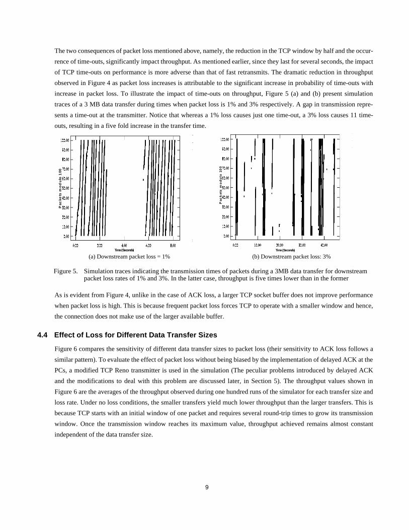
The two consequences of packet loss mentioned above, namely, the reduction in the TCP window by half and the occur-
rence of time-outs, significantly impact throughput. As mentioned earlier, since they last for several seconds, the impact
of TCP time-outs on performance is more adverse than that of fast retransmits. The dramatic reduction in throughput
observed in Figure 4 as packet loss increases is attributable to the significant increase in probability of time-outs with
increase in packet loss. To illustrate the impact of time-outs on throughput, Figure 5 (a) and (b) present simulation
traces of a 3 MB data transfer during times when packet loss is 1% and 3% respectively. A gap in transmission repre-
sents a time-out at the transmitter. Notice that whereas a 1% loss causes just one time-out, a 3% loss causes 11 time-
outs, resulting in a five fold increase in the transfer time.
As is evident from Figure 4, unlike in the case of ACK loss, a larger TCP socket buffer does not improve performance
when packet loss is high. This is because frequent packet loss forces TCP to operate with a smaller window and hence,
the connection does not make use of the larger available buffer.
4.4 Effect of Loss for Different Data Transfer Sizes
Figure 6 compares the sensitivity of different data transfer sizes to packet loss (their sensitivity to ACK loss follows a
similar pattern). To evaluate the effect of packet loss without being biased by the implementation of delayed ACK at the
PCs, a modified TCP Reno transmitter is used in the simulation (The peculiar problems introduced by delayed ACK
and the modifications to deal with this problem are discussed later, in Section 5). The throughput values shown in
Figure 6 are the averages of the throughput observed during one hundred runs of the simulator for each transfer size and
loss rate. Under no loss conditions, the smaller transfers yield much lower throughput than the larger transfers. This is
because TCP starts with an initial window of one packet and requires several round-trip times to grow its transmission
window. Once the transmission window reaches its maximum value, throughput achieved remains almost constant
independent of the data transfer size.
Time (Seconds)
Pac
kets
mo
du
lo 1
00
Time (Seconds)
Pac
ket
s m
od
ulo
10
0
(a) Downstream packet loss = 1% (b) Downstream packet loss: 3%
Figure 5. Simulation traces indicating the transmission times of packets during a 3MB data transfer for downstream packet loss rates of 1% and 3%. In the latter case, throughput is five times lower than in the former

10
As Figure 6 depicts, although packet loss affects data transfers of all sizes, the extent of its impact varies depending on
the data transfer size. For the simulated network, throughput degrades much more rapidly for data transfers of 300 KB
and above than for the smaller transfer sizes. For instance, when the packet loss rate increases to 5%, the average
throughput of 300KB data transfers drops from 2.8 Mbps to 0.2 Mbps, whereas for 30KB transfers, throughput only
changes from 1.5 Mbps to 0.9 Mbps. To see why this is the case, consider Figure 7, which contrasts the distribution of
throughput values observed during 30KB and 300KB data transfers. The 25 percentile, the median, and the 75 percen-
tile values, computed based on one hundred runs of the simulator for each loss rate and data transfer size, are shown.
The following observations can be made from Figure 7:
• At a loss rate of 1%, a majority of the 30KB data transfers are unaffected (Figure 7(a)). In contrast, over half of the
300KB data transfers experience a significant reduction in throughput, and one-fourth of the transfers achieve only a
third of the normal throughput (Figure 7(b)). This contrasting behavior is attributable to the relative durations of the
two data transfers. Since a 30KB transfer involves transmission of a few packets only (approximately 20 packets of
1.5 KB each), the probability that such a transfer experiences a packet loss is less than the probability that a longer
300KB transfer involving hundreds of packet transmissions experiences a loss. For instance, when the packet loss
Figure 6. Effect of packet loss on throughput, for different data transfer sizes from a PC with a TCP socket buffer of 8KB
0
0.5
1
1.5
2
2.5
3
0 100 200 300 400 500 600Data Transfer Size (KBytes)
Thr
ough
put (
Mbp
s)
0% packet loss
0.5% packet loss
1% packet loss
3% packet loss
5% packet loss
10% packet loss
Figure 7. Distribution of throughput achieved during one hundred runs of the simulator for 30 KB and 300 KB data transfers
0
0.5
1
1.5
2
0.01 0.03 0.05 0.1
Packet Loss Fraction
Thr
oug
hp
ut (
Mb
ps)
25 percentile
50 percentile
75 percentile
0
0.5
1
1.5
2
2.5
0.01 0.03 0.05 0.1Packet Loss Fraction
Thr
oug
hp
ut (
Mb
ps)
25 percentile
50 percentile
75 percentile
(a): 30KB data transfer (b): 300KB data transfer
11
rate is 1%, on an average, only one out of five data transfers of 30KB (20 packets) experience a loss. Furthermore,
because of their smaller duration, the 30KB transfers are unlikely to experience time-outs because multiple packet
losses. On the other hand, almost every data transfer of 300 KB experiences packet loss. More importantly, the prob-
ability of occurrence of multiple packet losses and of time-outs is also correspondingly higher for 300KB transfers.
• As the packet loss rate increases, 30KB data transfers too begin to experience the effects of packet loss: a 3% loss
reduces the median by 25% and a 5% loss by 66%. However, because of the shorter duration of the transfers, the
median and the 75 percentile values for 30KB transfers are much higher than the corresponding values for 300KB
data transfers. The different distribution of throughput values in the two cases accounts for the higher average
throughput of the 30KB transfers seen in Figure 6.
• At loss rates of 3% and higher, the 25 percentile throughput values for the 30KB and 300KB transfers are compara-
ble, implying that when packet loss impacts a data transfer instance, its effect on throughput is drastic, independent
of the data transfer size.
• Notice also the much larger difference between the 25 percentile and the 75 percentile values for the 30KB transfers,
as compared to the 300KB transfers. This implies that when packet loss is 3% or more, subscribers transferring
30KB of data are likely to observe significant variations in throughput. In contrast, at this loss rate, almost all 300KB
transfers are likely to feel the impact of packet losses.
From a data service operator’s perspective, the above discussion indicates that subscribers who invoke larger data trans-
fers are likely to experience the effects of packet loss earlier and to a greater extent than others.
5 Tuning TCP for Higher Performance by Setting TCP Buffer Size
To enhance TCP performance in lossy HFC networks, in the following sections we consider two complementary
approaches. The first approach involves adjusting the TCP socket buffer size to achieve maximum performance. The
second approach involves tuning TCP’s time-out and fast retransmit mechanisms to reduce the frequency and the dura-
tion of time outs, respectively. Although there are several other approaches for improving TCP performance, as men-
tioned in Section 3, we focus on the above mentioned approaches because of the simplicity and ease of their
implementation in current HFC network environments, with minimal changes only in TCP implementations of the local
servers.
5.1 Effect of Cable Modem Buffer Capacity on TCP Performance
A larger socket buffer allocation for a TCP connection permits a larger number of packets to be transmitted per unit
time, thereby making better utilization of the available bandwidth. Consequently, a larger TCP socket buffer enables a
significant increase in throughput when packet loss is not very high (see Figure 4). As already explained, an increase in
the socket buffer size also reduces the TCP connection’s vulnerability to ACK loss.
However, in an HFC network, a limit on the TCP socket buffer size is imposed by the buffering available at the CMs.
Buffers are provided in a CM to counteract the difference in transmission speeds between the downstream channel on
the HFC network (25 Mbps in our simulated network) and the 10Base-T connection between the CM and the PC (10

12
Mbps). Since the experiments described in Section 4 were targeted at understanding the effect of media errors, buffer-
ing at the CM was assumed to be unbounded. However, in reality, in order to be cost-competitive, most CM implemen-
tations are likely to have limited buffering. Figure 8 depicts the variation in throughput for different data transfer sizes
and socket buffer sizes over an HFC network in which the CMs have 10KB buffers. Since in this experiment, we are
interested in exploring the effect of bounded buffering at the CMs, the HFC network is assumed to be lossless. More-
over, in this experiment, each CM supports only one TCP connection.
As can be seen from Figure 8, when the socket buffer size increases from 8KB to 16KB, throughput almost doubles for
large transfers. However, when the buffer size is further increased to 24 KB, throughput reduces significantly for trans-
fers less than 8 MB. This drop in throughput is attributable to packet losses that result from buffer overruns at the CM.
Recall that during the start up of a connection, in the slow-start phase, the TCP transmitter grows its window exponen-
tially, doubling its window for each round-trip. The window increase continues either until the window reaches the
Figure 8. Effect of CM buffer size on throughput of a TCP connection. In this simulation, there were no media errors at the physical layer. The CM buffer was assumed to be 10 KB
0
1
2
3
4
5
6
7
0 1000 2000 3000 4000 5000 6000 7000 8000
Data transfer size (KBytes)
Thr
ough
put (
Mbp
s)
Socket Buffer = 8KB
Socket Buffer = 16KBSocket Buffer = 24KB
Socket Buffer = 48KB
Time (Seconds)
Pa
ck
ets
mo
du
lo 1
00
Figure 9. Illustration of time-out that occurs during the slow-start phase of a TCP connection because the socket buffer size is set to be much larger than the CM buffer size

13
socket buffer size, or until packet loss occurs. Since it is possible that an entire window of packets could be transmitted
consecutively by a local server to the PC, all of these packets could arrive in succession at the CM, at the speed of the
HFC downstream channel. Because of the slower speed of the outgoing 10Base-T connection from the CM, packets
arriving in succession need to be queued by the CM. When the TCP socket buffer size is much higher than the CM
buffer capacity, the CM may not be able to accommodate the arriving packets. Hence, buffer overruns may occur at the
CM, resulting in several packet drops. Since the fast retransmit strategy of TCP is not effective when multiple packet
drops occur in a window, the transmitter has to recover only after a time-out (see Figure 9).
Following the time-out, when slow-start is invoked again, the transmitter maintains a threshold that it sets to half the
window size at which time-out occurred. When the window size increases to reach this threshold, the TCP transmitter
moves into the congestion avoidance mode in which it begins to increase the window linearly, by one packet every
round-trip. As the window increases, eventually buffer overruns still occur, but owing to the linear increase in the win-
dow, only a single packet is dropped at the CM. Consequently, the transmitter recovers from the loss using fast retrans-
mit, instead of having to time-out (see Figure 9). However, the long initial time-out period significantly impacts the
throughput achieved for data transfers of 8 MB and less for socket buffer sizes of 24 and 48 KB (see Figure 8). Larger
transfers are able to benefit from the larger socket buffer size.
The above experiment highlights the need to consider the CM buffer capacity before setting the socket buffer size for
TCP connections. Another factor that must be considered in deciding the socket buffer size is the number of connec-
tions simultaneously supported via a CM. Many common Web browsers frequently open multiple simultaneous con-
nections in an attempt to retrieve Web objects in parallel. Figure 10 illustrates the performance observed when three
simultaneous TCP connections, each transferring 300 KB, share the 10 KB buffer of a CM. In this case, packets could
arrive over all three connections simultaneously and can result in buffer overruns. For the same socket buffer size, larger
the number of connections, greater the probability of buffer overruns. In Figure 10, the smaller socket buffer size per-
forms the best. As the socket buffer size per connection increase, throughput degrades.
0
1
2
3
4
5
6
7
8
9
8 16 24 48Socket Buffer Size (KBytes)
Thr
ough
put (
Mbp
s)
Connection 3
Connection 2
Connection 1
Figure 10. Variation in throughput for different TCP socket buffer sizes when three connections simultaneously access the HFC network via a CM with a 10 KB buffer

14
5.2 Determining the TCP Buffer Size
To compute the socket buffer size of a TCP connection, let B represent the TCP socket buffer size and C the buffer
capacity of the CM, both represented in terms of TCP packets. Let P represent the maximum TCP packet size in bits.
Suppose that only one connection is established via the CM. As explained earlier, the socket buffer size setting that
ensures data transfers without time-out must be determined by considering the case when an entire buffer full of data
packets are transmitted at the maximum rate to a CM. Ignoring TCP/IP and link protocol header overheads for simplic-
ity, for the simulated HFC network configuration with a downstream channel rate of 25 Mbps, the time to receive a win-
dow full of packets at the CM is: microseconds. The CM begins transmission over the 10Base-T connection to the
PC connected to it only after the first packet has been fully received from the HFC downstream channel, at which time
the available buffering at the CM is C-1. From this time, B-1 packets are received by the CM at the rate of 25Mbps and
transferred from the CM at the rate of 10 Mbps. Thus, net accumulation at the CM during this period is:
Mbits. To avoid any buffer overruns at the CM, the necessary condition is:
Since time-outs occur during slow-start only when multiple packet drops occur in a window, the above condition can be
relaxed by permitting at most one packet drop in a window. This yields the relation: In the simu-
lated network, for a CM buffer of 10KB (7 packets), the maximum socket buffer size can be computed from the above
equation to be 19KB, which matches the results from Figure 8.
When there are n connections supported by the same CM, in order to guarantee that time-out does not occur, in the pes-
simistic case, no more than one packet loss should occur during buffer overflow. This leads to the condi-
tion: .
From the above equations, the TCP socket buffer size setting can be computed based on the buffering at the CM and the
number of simultaneous connections to be used. Since the per-connection throughput is directly related to the TCP
socket buffer size setting, the average rather than the maximum number of simultaneous connections can be used in the
computation above. Alternatively, to ensure a minimum throughput per connection, a data service operator may wish to
impose a restriction on the maximum number of simultaneous connections supported from each subscriber PC. Since
the effective socket buffer size used for a TCP connection is the minimum of the values supported at each ends of the
connection, the socket buffer size computed above can be enforced by setting the buffers of connections initiated from
the local servers to the above value, without the need to modify subscribers’ PC configurations.
6 Tuning TCP for Higher Performance by Reducing the Effect of Time-Outs
Having determined the optimal buffer size setting for a TCP connection, we now explore various facets of TCP that can
be modified in order to reduce the effect of TCP time-outs. Considering the practical implementation difficulties, we
make several recommendations that can be easily incorporated in current TCP implementations being used in HFC net-
works.
B P⋅25-----------
B 1–( ) P⋅25------------------------- 25 10–( )⋅ C
B 1–( ) P 15⋅ ⋅25------------------------------------ 1+≥
CB 1–( ) P 15⋅ ⋅
25------------------------------------≥
CB n⋅ 1–( ) P 15⋅ ⋅
25-------------------------------------------≥

15
6.1 Effect of Delayed ACK
As indicated in Section 4, one of the causes of TCP time-outs is loss of several successive ACKs. Although increasing
the socket buffer size can reduce the probability of time-outs due to ACK losses, as seen in Section 5, the CM buffer
capacity imposes a limit on the TCP socket buffer setting. In this section, we explore approach for minimizing the effect
of ACK losses. Towards this end, we study how the effect that support for delayed ACK in TCP implementations of
subscriber PCs has on performance.
The adverse effects of delayed ACK implementation in TCP receivers operating over ATM networks are described in
[5]. We have observed that delayed ACK has a deleterious effect on performance of Web and FTP applications in con-
ventional LANs and in HFC networks as well. To illustrate these effects, we observe that in most TCP implementations,
following the establishment of the TCP connection, the transmission window of the host initiating the connection is 1
packet and that of the other end of the connection is 2 packets. This is because although both ends of the connection
start with an initial window of 1 packet, the last ACK in the TCP three-way handshake sequence, SYN - SYN_ACK -
ACK, causes the window of the host accepting the TCP connection to be increased by one packet. The difference in the
initial TCP windows has different implications for FTP and HTTP applications:
• As illustrated in Figure 11(a), when a subscriber starts an FTP session with a server, a control connection is first
established between the subscriber’s PC and the server. Get and Put requests for files are transmitted from the sub-
scriber PC to the server over the control connection. The server then sets up separate TCP connections for each Get
or Put request. Since the server is the connection initiator, its initial transmission window is 1 packet. When data is
transferred from the server to fulfil a Get request, the server starts off by transmitting one packet and waiting for an
Subscriber PCFTP Client
ServerFTP Server
ControlConnectionSet-Up
SYN
SYN_ACK
ACK
FTP GET
SYN_ACK
ACK
SYNData ConnectionSet-Up
TCP Window: 2 pktsTCP Window: 1pkt
Subscriber PC
HTTP Client
Server
HTTP Server
HTTPConnectionSet-Up
SYN
SYN_ACK
ACK
HTTP GET
TCP Window: 1pkt
TCP Window: 2pkts
Data Transfer
Data Transfer Begins
200ms delayfor 1st ACK
Data Pkt
Data Pkts
ACK
GET Response Header
Data Pkt
ACK
200ms delayfor 2nd ACK
Data Pkts
TCP Window: 2pkts
TCP Window: 3pkts
Figure 11. Illustration of the effect of delayed ACK implementation in TCP stacks of subscriber PCs on performance of (a) FTP and (b) HTTP data transfers. In both cases, the initial 200ms delay for the first ACK from the subscriber PC reduces throughput by over 30% for data transfers sizes of upto 150 KB
(a) (b)

16
ACK. Since the TCP stack in the subscriber PC supports delayed ACK, the subscriber PC waits for upto 200ms for
subsequent packets, before generating an ACK for received packet. This long initial wait time significantly impacts
performance. Figure 12 illustrates that delayed ACK implementation at subscriber PCs reduces throughput by more
than 50% for transfers below 150 KB and by less than 10% for transfers of 5MB and more. Note that because the ini-
tial transmission window of the subscriber PC is 2 packets, Put requests do not experience this problem.
• HTTP requests experience a different problem. In this case, the subscriber PC first initiates the TCP connection to
the server and transmits the HTTP request, either to Get or Post data. Unlike FTP, data transmission to or from the
server using HTTP occurs over the same connection. Since the subscriber PC initiates the TCP connection, the
server has an initial window of 2 packets. Get requests, which are the most common form of HTTP access, may not
experience the initial 200ms delay if the server fully utilizes its transmission window. This is because, the server can
transmit two maximum sized packets, thereby forcing an immediate ACK from the subscriber PC as per RFC 1122.
However, many HTTP server implementations (e.g., NCSA 1.5, Netscape Enterprise Server) transmit the HTTP
response header separate from the data, as the first packet. Typically, the header is smaller than the maximum sized
TCP data packet. Because of the transmission window restriction and the size of the data read from disk (typically
8KB), following the HTTP Get response header, the server can transmit at most one other maximum sized data
packet before it has to wait for an ACK from the subscriber PC. Since it receives less than two maximum sized pack-
ets worth of data, the subscriber PC delays its ACK, thereby resulting in an initial delay of upto 200ms for all HTTP
Get responses.
A simple way to avoid the above problems without requiring any change in the receiver’s TCP implementation is to
increase the initial setting of the TCP window size used during slow-start at the local servers to 2 packets (see
Figure 12).
Another drawback of delayed ACK is the reaction it induces in TCP connections when ACK loss happens. Figure 13
illustrates that for a 3MB data transfer, when upstream ACK loss happens, a receiver that does not implement delayed
Figure 12. Illustrating of the deleterious impact that delayed ACK implementation at subscriber PCs can have on throughput of HTTP and FTP data transfers. Using an initial window of 2 packets for the TCP slow-start implementation at the local servers avoids the throughput degradation for data transfers of 150 KB and less.
0
0.5
1
1.5
2
2.5
3
3.5
0 200 400 600 800 1000 1200 1400 1600
Data Transfer Size (KBytes)
Thr
ough
put (
Mbp
s)
Without Delayed ACK
With Delayed ACK
With Delayed ACK and Modified Slow-Start

17
ACK remarkably out-performs a receiver that implements delayed ACK. The difference in performance is attributable
to the 50% reduction in number of ACKs when a receiver implements delayed ACK, since only one ACK is transmitted
for every two received packets. This reduction in ACKs makes the TCP connection more vulnerable to experiencing
time-outs because of loss of all the ACKs in a window. Furthermore, even in cases when time-outs do not occur,
because of the reduction in number of ACKs, the transmitter has to wait for longer time periods for an ACK that follows
a lost ACK. The large degradation in performance observed in Figure 13 indicates the need to increase the frequency of
ACKs during communication over lossy HFC networks.
Avoiding delayed ACK at the receiver does not have the same dramatic effect when the losses occur in the downstream
channels rather than on the upstream channels. This is because TCP Reno does not delay its ACKs when it notices
packets arriving out of sequence. In contrast, since the earlier TCP Tahoe implementation continues to delay ACKs
even after it notices a packet loss, PCs that implement TCP Tahoe are likely to see a significant improvement in perfor-
mance if delayed ACK is not used.
Avoiding the usage of delayed ACK requires changes in TCP implementations of the several hundred thousands sub-
scribers’ PCs, an enormous and unrealistic task. Moreover, applications such as telnet that transmit small TCP packets
frequently in both directions over a TCP connection benefit significantly from delayed ACK implementation. In the
next section, we discuss changes to TCP implementations at the local servers that can overcome the drawbacks of using
delayed ACK in the PCs for bulk transfer applications such as FTP and HTTP.
6.2 Setting TCP MSS Values
Observe that the number of ACKs transmitted from a TCP receiver in a round-trip time is determined not only by the
socket buffer size but also by the size of each data packet, referred to as the maximum segment size, MSS. The smaller
the MSS value, the larger the number of ACKs in a window. To increase the robustness of TCP connections to ACK
loss, it is more efficient to use smaller MSS values during periods of loss. Figure 14 illustrates the improvement in per-
formance that can be obtained from reducing the MSS, even when the TCP receiver implements the delayed ACK strat-
egy. Importantly, since the MSS value for a downstream data transfer is determined by the local server itself, TCP
Figure 13. Implementation of delayed ACK increases a TCP connection’s vulnerability to ACK loss. This example involves a 3MB data transfer over a connection with maximum window size of 8 KB
0
0.5
1
1.5
2
2.5
3
3.5
0 0.05 0.1 0.15 0.2 0.25 0.3 0.35 0.4
Upstream ACK Loss
Thr
ough
put (
Mbp
s)
Without Delayed ACK
With Delayed ACK

18
connections originating from the local server can be made more robust to upstream ACK loss by configuring the server
to use a smaller MSS.
There are however several trade-offs that must be considered when deciding whether the smaller MSS value should be
used always, or only during times of significant upstream loss. On the positive side, besides offering greater resilience
to ACK loss, the smaller MSS may also decrease the packet loss rate (e.g., depending on the burstiness of errors, if the
loss probability of 1KB packets is 10%, the loss probability of 0.5 KB packets will be between 5 and 10%). Another
advantage of smaller MSS is that a larger number of ACKs are generated by the receiver, which increases the probabil-
ity that the transmitter receives three dupACKs necessary for fast retransmit to be triggered following a packet loss. On
the negative side, a smaller MSS results in greater TCP/IP and link protocol header overhead. Furthermore, TCP’s slow-
start and congestion avoidance mechanisms are slowed down for the smaller MSS since TCP’s slow-start and conges-
tion avoidance mechanisms increase the transmission window in terms of packets, irrespective of the MSS in use. The
above trade-offs must be considered for the specific network conditions to choose the appropriate MSS value to use.
6.3 Using a Finer Granularity Retransmission Timer
An obvious improvement to enable TCP to react more quickly to network losses is to use a finer granularity timer than
the 500ms timer used in most current implementations. This would enable the TCP transmitter to obtain a tighter upper
bound on the round-trip times, which in turn results in a reduction in the time that elapses before the transmitter times
out and retransmits a lost packet. Current TCP implementations use two types of timers: a 200ms timer that is used for
supporting delayed ACK, and a 500 ms timer that is used for computing round-trip times. Using the 200ms timer to
estimate round-trip delays as well can increase TCP’s reactivity without overly increasing its implementation overhead.
As illustrated in Figure 15 (a) and (b), this modification in the timer granularity improves performance both for
upstream and downstream losses. The degree of improvement achieved depends on the percentage of losses experi-
enced over the network. For example, when network loss on the downstream is 3%, this simple modification yields an
almost two-fold increase in performance.
Figure 14. Throughput variation with ACK loss for different MSS values for a 3 MB data transfer. By using a smaller MSS, a server can reduce the effect of ACK loss on throughput
0
0.5
1
1.5
2
2.5
3
0 0.05 0.1 0.15 0.2 0.25 0.3 0.35 0.4
Upstream ACK Loss
Thr
ough
put (
Mbp
s)
MSS: 536 bytes
MSS: 966 bytes
MSS: 1460 bytes

19
6.4 Using “Super” Fast Retransmit
A further improvement in performance can be obtained by tuning TCP’s fast retransmit mechanism to HFC networks.
Since in-sequence delivery of packets is guaranteed over the HFC network and all the way to the local server complex,
the receipt of the first dupACK at the server is a clear signal that a data packet has been lost. However, since TCP has
been designed to operate in more general networks, where packets may be routed via different paths and may therefore
arrive out of sequence, the TCP transmitter waits for three dupACKs to arrive before retransmitting a missing packet. In
networks where packets are guaranteed to be received in order, this strategy of TCP unnecessarily delays the detection
and retransmission of lost packets. Even more significantly this strategy makes TCP more vulnerable to time-outs dur-
ing periods of high loss: since at least three dupACKs are necessary to trigger a fast retransmit, TCP requires the oper-
ating window to be at least four packets for the fast retransmit mechanism to be effective. During periods of significant
loss, TCP’s operating window drops many times below four, and a single packet loss during the time when the window
stays below four (which could be up to two round-trip times) results in a time-out.
We propose to modify TCP implementations at the local servers of HFC networks so that fast retransmit is triggered
after the first dupACK is received at the server. By initiating retransmission earlier, this approach, referred to as “super
fast retransmit”, speeds up the recovery of TCP from isolated packet losses. Much more significantly, super fast
retransmit reduces the probability of time-outs: since it requires only a single dupACK to retransmit a packet, super fast
retransmit is effective even when the window size drops to 2. In addition, super fast retransmit increases the possibility
that the TCP transmitter will detect and recover from multiple packet losses in a transmission window, as demonstrated
in Figure 16. In this example, when two packets, 11 and 14 are lost, a transmitter that implements fast retransmit expe-
riences a time-out for packet 14 since it receives only two dupACKs for this packet. In comparison, a transmitter using
super fast retransmit retransmits packet 14 soon after receiving the first dupACK and is thereby able to recover from the
packet losses without experiencing a time-out.
The effects of increasing the retransmission timer granularity and employing super fast retransmit are complementary.
Figure 15. Increase in performance from increasing the granularity of TCP’s retransmission timer to 200 ms (a) during downstream packet loss, and (b) during upstream ACK loss. In this example, a 3 MB data transfer was initiated from a local server to a subscriber’s PC
0
0.5
1
1.5
2
2.5
3
0 0.01 0.02 0.03 0.04 0.05 0.06 0.07
Downstream Packet Los s
Thr
oug
hp
ut (
Mb
ps)
Normal TCP
TCP with 200ms Timer
0
0.5
1
1.5
2
2.5
3
0 0.05 0.1 0.15 0.2 0.25 0.3 0.35 0.4Upstream ACK Loss
Thr
ough
put (
Mbp
s)
Normal TCP
TCP with 200ms Timer
(a) (b)

20
trates the performance improvement that can be obtained from using a TCP implementation with these modifications
during different network loss conditions for a 3MB data transfer.
Figure 18 illustrates the performance improvements for different transfer sizes. For the loss rates shown in the figure,
the modified TCP performs uniformly well for data transfers of 50KB and above, offering performance improvements
ranging from 25% to 300%. For smaller transfers, of 50KB and less, the effect of modified TCP is less dramatic for loss
rates of 5% and less. At higher loss rates, the performance improvements even for small transfer sizes are very signifi-
cant. For instance, for a 30KB data transfer, at a 10% loss rate, modified TCP doubles the achieved throughput.
1112131415161718
11
1920
1111
11111111
14
1414
Transmitter times-out when
1112131415161718
11
1920
1111
11111111
14
1414
Transmitter recovers 14from loss of packets11 and 14 when using
Transmitter Receiver ReceiverTransmitter
(a) (b)
Figure 16. Demonstration of the advantages of super fast retransmit when multiple packet losses occur in a transmission window of size 8 packets. (a) Fast retransmit causes a time-out when packets 11 and 14 are lost. (b) Super fast retransmit is able to recover from the two packets
Lost Packet
using fast retransmit
super fast retransmit
(Packet No) (ACK No) (Packet No) (ACK No)
14
Figure 17. The complementary effects of increasing the retransmission timer granularity and invoking super fast retransmit for a 3 MB data transfer between a local server and a subscriber’s PC
0
0.5
1
1.5
2
2.5
3
0 0.01 0.02 0.03 0.04 0.05 0.06 0.07Downstream Packet Loss
Thr
ough
put (
Mbp
s)
Normal TCP
TCP with 200ms Timer
TCP with 200ms Timer and Super fast retransmit

21
7 Implications for Broadband Data Service Operators
In this section, we discuss some implications of our analysis of TCP performance over HFC networks for operators and
equipment manufacturers for the broadband data service market.
• Viability of data services even under harsh upstream network conditions: In recent times, critics of HFC networks
have doubted the viability of providing data services over such networks, mainly on account of the high error rates
on the upstream channels [7]. Our analysis indicates that for downstream access, TCP connections can be tuned to
be highly robust to loss of ACKs on the upstream channel, so that acceptable performance can be achieved even
under harsh upstream conditions. For example, with the enhancements proposed in the previous sections, even a
20% loss of ACKs on the upstream channels results in less than 10% reduction in TCP performance.
• Need to optimize performance of the HFC networks by careful design and maintenance: To the many who have
believed that data communication protocols are tolerant to loss, our analysis has demonstrated that a low (1%) down-
stream packet loss can degrade performance by up to 50%. To meet subscriber expectations, data service operators
must strive to tune and maintain the physical network to reduce RF impairments. Considering the predominance of
downstream data transfers, the downstream channels must be especially carefully tuned. Forward error correction
and bit interleaving techniques incorporated in the CMs can mask physical layer errors from the TCP layer. Proac-
tive monitoring can alert operators about impairments before subscribers notice the problem.
In the future, when applications transferring data upstream become commonly used, upstream error rates must be
strictly controlled. Based on our analysis, we conjecture that upstream packet loss, more than the limited upstream
spectrum available, is likely to limit the achievable throughput. Channel error sensing and frequency agility capabil-
ities in the CMs can help in sustaining high performance levels on the upstream channels.
• Implications for CM-SCS architectures: In many first generation architectures, the SCS themselves transmit on the
upstream frequencies and a separate frequency translator is used to reflect upstream transmissions on the down-
stream channels. Since noise on the upstream channels is also reflected downstream, in such CM-SCS architectures,
0
0.5
1
1.5
2
2.5
0 100 200 300 400 500 600Data Transfer Size (KBytes)
Thr
ough
put (
Mbp
s)
1% packet loss, TCP
1% packet loss, Modified TCP
5% packet loss, TCP
5% packet loss, Modified TCP
10% packet loss, TCP
10% packet loss, Modified TCP
Figure 18. Illustration of the performance improvements that modified TCP offers for different data transfer sizes and different data packet loss rates

22
even transmissions from the server complex to subscribers’ PCs may be affected by upstream noise in the HFC net-
work. Our analysis also indicates a key advantage in CM-SCS architectures that separate upstream transmissions
from CMs and downstream transmissions from the server complex.
The TCP performance evaluations can also serve as the basis for innovative load balancing algorithms for HFC net-
works. For instance, an SCS that supports multiple upstream channels can decide based on the error rates observed
on the channels to allocate subscribers who are predominantly using the network for downstream transfers to the more
error prone upstream channels. Other subscribers who are using the network for upstream data transfers can be allo-
cated to the more reliable upstream channels.
• Tuning TCP socket buffer settings for optimal performance: Until now, very little attention has been placed to tune
the TCP connection parameters to the specific CM architecture. We have demonstrated the performance advantages
that can be obtained simply by tuning the TCP socket buffer parameters based on the buffering capacity of the CMs
and the number of simultaneous connections supported by the CM.
We are beginning to implement and experimentally evaluate the impact of our proposed modifications in real-world
HFC networks. Since a significant percentage of subscribers not only access the local server complex, but also to the
Internet, another area of focus is to develop mechanisms for enhancing performance for such remote accesses. Another
area of our research is to apply the understanding of TCP’s behavior to effectively monitor, manage, and diagnose HFC
networks.
References
[1] A. Bakre and B. Badrinath. I-TCP: Indirect TCP for mobile hosts. In Proceedings of 15th International Confer-
ence on Distributed Computing Systems (ICDCS), May 1995.
[2] H. Balakrishnan, S. Seshan, E. Amir, and R. H. Katz. Improving TCP/IP performance over wireless networks. In
Proc. of 1st ACM Conference on Mobile Computing and Networking, Berkeley, California, Nov. 1995.
[3] R. Braden. Requirements for Internet hosts – communication layers. Internet Request for Comments, RFC 1122,
October 1989.
[4] L. S. Brakmo and L. L. Peterson. TCP vegas: End to end congestion avoidance on a global Internet. IEEE Journal
on Selected Areas in Communications, 13:1465–1480, Oct 1995.
[5] D. Comer and J. Lin. TCP buffering and performance over an ATM network. Journal of Internetworking:
Research and Experience, 6(1):1–13, March 1995.
[6] J. Dail, M. Dajer, C.-C. Li, P. Magill, C. Siller, K. Sriram, and N. Whitaker. Adaptive digital access protocol: A
MAC protocol for multiservice broadband access networks. IEEE Communications Magazine, 34(3):104–112,
March 1996.
[7] J. Dvorak. The looming cable modem fiasco. PC Magazine, September 1995.
[8] C. Eldering, N. Himayat, and F. Gardner. CATV return path characterization for reliable communications. IEEE
Communications Magazine, 33(8):62–69, August 1995.
[9] J. C. Hoe. Improving the start-up behavior of a congestion control scheme for TCP. In Proceedings of ACM SIG-

23
COMM’96, Palo Alto, CA, pages 270–280, August 1996.
[10] V. Jacobson. Congestion avoidance and control. ACM SIGCOMM Symposium, pages 314–329, August 16-19,
1988.
[11] M. Mathis and J. Mahdavi. Forward acknowledgement: Refining TCP congestion control. In Proceedings of ACM
SIGCOMM’96, Palo Alto, CA, pages 281–292, August 1996.
[12] E. Perry and S. Ramanathan. Network management for residential broadband interactive data services. IEEE
Communications Magazine, Special Issue on Broadband Access, November 1996.
[13] W. Stevens. TCP/IP Illustrated, Vol. 1, Addison-Wesley, MA, 1994.
Recommended