Transmit CombinersYou’re heard, loud and clear.
Bird® Technologies Group (BTG) is a global, innovative supplier
of RF products, systems, services and educational solutions.
Combining the industry leading brands of both Bird Electronic
and TX RX Systems in one company reinforces the BTG
commitment to providing RF Measurement and Management in
Your World.
Our portfolio includes hardware, software, components and services. We
offer these innovative products and services through our industry lead-
ing product line brands, Bird Electronic Corp and TX RX Systems. We
provide test instruments that are highly accurate, rugged and easy to
use. Industry leading components and products such as site analyzers,
wattmeters, digital sensors, samplers, antennas, signal boosters,
and tower mounted amplifiers. Furthermore, we offer dependable
engineering, calibration and educational services for land mobile radio,
cellular, semiconductor, broadcast, medical, military and government
applications.
All BTG products can be serviced and calibrated by the Bird Service
Center (BSC). BSC provides a full range of service and support. With over
130 years of combined product and calibration experience, our service
technicians and product experts offer reliable service and customer care.
Bird Service Centers and Service Partners are located World Wide
providing a full range of service and support for your Bird Products.
Catalogs offered by Bird Technologies Group(To view or download go to www.bird-technologies.com)
Bird General Catalog
RF & Microwave Components Catalog
Transmit Combiners Catalog
Cavity Filters & Duplexers Catalog
Antennas Catalog
Tower Top Amplifiers, Receiver Multicouplers & Preselectors Catalog
Isolators & Loads Catalog
In-Building Coverage Catalog (Signal Boosters & Accessories)
Bird® Technologies Group combines the industry leading brands of both Bird Electronic and TX RX Systems and is a global, innovative supplier of RF products,systems, services and educational solutions. Bird® Technologies Group reserved the right to modify specifications or discontinue any product without notice.
You’re heard, loud and clear.
30303 Aurora Rd. :: Solon, OH 44139 :: 866.695.4569 :: www.bird-technologies.com
©2009 Bird Technologies GroupTransCom-10142009

TransmiTTer Combiners
tel: 866.695.4569 fax: 716.549.4772 e: [email protected] Technologies group reserVes The righT To ModiFY speciFicATions or disconTinue AnY producT WiThouT noTice TerMs And condiTions posTed on hTTp://WWW.Bird-Technologies.coM/sAles/BTg_Tc.pdF
1
Table of ConTenTsCombiners/multicouplers Page 2T-Pass Combiners Page 3star Junction Combiners/multicouplers Page 11airline Junction Combiner Page 13Compact Ceramic Combiners Page 14Control station Combiners Page 15multiband Control station Combiner Page 18

Combiners/mulTiCouPlers118-960 MHz
Bird Technologies group, TX rX systems brand time-proven combiners and multicou-plers provide design security for any multi-channel radio system. From the most complex multi-site homeland security system to the simplest 2-channel private system, our products enables unsurpassed flexibility to accommodate the most challenging frequency plans, as well as future expandability. The same architecture used for transmitter combining can also be used as a preselector in complex receive systems where there is not sufficient guard-band to use combline bandpass filters. proven low-loss and low piM construction tech-niques are used such as welded cavity construction; silver- plated loops, Alballoy®- plated integrated loop plates and connectors; as well as a unique fingerstock-free high conductivity silver- plated tuning probe. our patented internal temperature compensation insures that transmitter cavities remain in tune even when connected to high duty cycle transmitters. coupled with either peg rack or 19” rack and TX rX’s own high-isolation transmitter iso-lators, the TX rX combining and multicoupling system continues to hold its position as the gold standard in the demanding private and public safety market. And all TX rX products are designed and manufactured in the usA.
TX rX provides multicoupling systems, not “one-size-tries-to-fit-all” products. each system is designed and configured for the specific site at which it is to be used. intermodulation studies as well as transmitter noise and receiver desense estimates are used to design the unit with the required isolation characteristics for the environment where it will be used.
tel: 866.695.4569 fax: 716.549.4772 e: [email protected] Technologies group reserVes The righT To ModiFY speciFicATions or disconTinue AnY producT
WiThouT noTice TerMs And condiTions posTed on hTTp://WWW.Bird-Technologies.coM/sAles/BTg_Tc.pdF
2
T-Pass®
Broadband architecture of the T-pass® circuit and coaxial cavities mitigates equipment obsolescence and facilitates ease of system reconfiguration when re-banding is necessaryeach system configured for optimum performanceideal for applications with minimal guard band between transmit and receive frequencies
star-Junction
high performance specifications with narrow adjacent channel spacing and low insertion loss5.8” square cavity or 8” round cavity with 19” rack mount configuration for space efficiencysame length interconnect for ease of retuning and expansion in the field

T-Pass Combiners Technical Specifications118-136 MHz
notes: 1. -nn in model number represents the number of channels. 2. consult factory on T-pass multicouplers for frequencies below 118 Mhz. 3. Models available with 5W/60W loads. same specifications as 25W and 100W models, except load power. 4. -Mc option reduces maximum number of channels to ten 10-inch or twelve 6.625-inch channels per rack. 5. -lr systems are tuned and tested on customer frequencies, then disassembled for shipping. 6. rack depth with cavity tuning rods at maximum frequency. rod travel is approximately 3.3” (84 mm).
Typical insertion loss and maximum input Power
73-35a-01-series systems (6.625” Cavity Diameter)
Tx-Txseparation
Cavityloss
maximumPower
loss (db) vs. no. of channels
2 4 12
1 Mhz -1.5 dB 150 W -2.6 -2.7 -3.3
250 khz -1.5 dB 150 W -2.7 -3.0 -3.6100 khz -1.5 dB 150 W -3.2 -4.0 -5.1
75 khz -2.0 dB 135 W -3.6 -4.5 -5.6
50 khz use 10” cavities at this separation
73-35a-05-series systems (10” Cavity Diameter)
Tx-Txseparation
Cavityloss
maximumPower
loss (db) vs. no. of channels
2 4 12
1 Mhz -1.5 dB 150 W -2.6 -2.7 -3.2
250 khz -1.5 dB 150 W -2.6 -2.9 -3.4100 khz -1.5 dB 150 W -2.9 -3.6 -4.475 khz -2.0 dB 150 W -3.5 -4.1 -4.950 khz -2.5 dB 130 W -4.1 -4.8 -5.7
73-35A-05-series systems10” diameter Quarterwave, Fo=124 Mhz
offset from Fo (Mhz)
Atte
nuat
ion
(dB
)
73-35A-01 series systems6.625” diameterQuarterwave Fo=124Mhz
offset from Fo (Mhz)
Atte
nuat
ion
(dB
)
tel: 866.695.4569 fax: 716.549.4772 e: [email protected] Technologies group reserVes The righT To ModiFY speciFicATions or disconTinue AnY producT WiThouT noTice TerMs And condiTions posTed on hTTp://WWW.Bird-Technologies.coM/sAles/BTg_Tc.pdF
3
model numbers/ frequency
73-35A-01-2B-nn73-35A-01-2D-nn73-35A-05-2B-nn73-35A-05-2D-nn
118-136 Mhz
Cavity Type and Diameter
73-35A-01-2B-nn73-35A-01-2D-nn73-35A-05-2B-nn73-35A-05-2D-nn
Quarterwave, 6.625” (168 mm)Quarterwave, 10” (254 mm)
maximum Continuous Transmit Power
see table on right
isolator load Pwr (Continous) [note 3]
73-35A-01-2B-nn73-35A-01-2D-nn73-35A-05-2B-nn73-35A-05-2D-nn
5W/25W5W/100W5W/25W5W/100W
min Tx-Tx separation @ Cavity loss
73-35A-01-2B-nn73-35A-01-2D-nn73-35A-05-2B-nn73-35A-05-2D-nn
100 khz @ -1.5 dB; 60 khz @ -2.5 dB 80 khz @ -1.5 dB; 45 khz @ -2.5 dB
Typical Tx-Tx isolation @ min separation
-70 dB
Typical antenna - TX isolation
-60 dB
Typical TX noise suppression
depends on cavity loss (see curves below)
normal inputimpedance
50 ohms
maximum input return loss (VsWr)
-20 dB (1.22:1)
Temperature range -30 to +60 celsius
Connectors, input & antenna
n
mechanical mounting peg rack®
mounting options [notes 4,5]
73-35A-01-2B-nn73-35A-01-2D-nn73-35A-05-2B-nn73-35A-05-2D-nn
Mc: 19” rackmount adapter plates, 17.5” highlr: system supplied without peg rack®
maximum Channels Per rack [notes 4]
73-35A-01-2B-nn73-35A-01-2D-nn73-35A-05-2B-nn73-35A-05-2D-nn
15151212
Dimensions [notes 6] 73-35A-01-2B-nn73-35A-01-2D-nn73-35A-05-2B-nn73-35A-05-2D-nn
65.25”hx24”Wx40.25”d (1659x610x1022mm)79.5”hx24”Wx42.5”d (2019x610x1080 mm)
Weight, lb (Kg) - basic single-Channel
73-35A-01-2B-nn73-35A-01-2D-nn73-35A-05-2B-nn73-35A-05-2D-nn
38 (17.2)39 (17.7)44 (19.9)45 (20.4)
Weight, lb (Kg) - expansion Channel assy
73-35A-01-2B-nn73-35A-01-2D-nn73-35A-05-2B-nn73-35A-05-2D-nn
16 (7.2)17 (7.7)21 (9.5)22 (10.0)

T-Pass Combiners Technical Specifications
132-174 MHz
notes: 1. -nn in model number represents the number of channels. 2. consult factory on T-pass multicouplers for frequencies above 174 Mhz. 3. Models available with 5W/60W loads. same specifications as 25W and 100W models, except load power. 4. -Mc option reduces maximum number of channels to ten 10-inch or twelve 6.625-inch channels per rack. 5. -lr systems are tuned and tested on customer frequencies, then disassembled for shipping. 6. rack depth with cavity tuning rods at maximum frequency. rod travel is approximately 5.4” (137 mm).
73-38-05-series systems10” diameter Quarterwave, Fo=160 Mhz
offset from Fo (Mhz)
Atte
nuat
ion
(dB
)
Typical insertion loss and maximum input Power
73-38-01-series systems (6.625” Cavity Diameter)
Tx-Txseparation
Cavityloss
maximumPower
loss (db) vs. no. of channels
2 4 12
1 Mhz -1.5 dB 150 W -2.6 -2.7 -3.3
250 khz -1.5 dB 150 W -3.3 -4.5 -5.7100 khz -2.0 dB 135 W -3.6 -4.5 -5.575 khz -2.5 dB 115 W -4.3 -5.4 -6.750 khz use 10” cavities at this separation
73-38-05-series systems (10” Cavity Diameter)
Tx-Txseparation
Cavityloss
maximumPower
loss (db) vs. no. of channels
2 4 121 Mhz -1.5 dB 150 W -2.6 -2.7 -3.1250 khz -1.5 dB 150 W -2.9 -3.4 -4.0100 khz -1.5 dB 150 W -3.0 -3.7 -4.575 khz -2.0 dB 150 W -3.5 -4.2 -5.050 khz -2.5 dB 130 W -4.1 -5.0 -6.1
73-38-01 series systems6.625” diameter Quarterwave, Fo=160 Mhz
offset from Fo (Mhz)
Atte
nuat
ion
(dB
)
tel: 866.695.4569 fax: 716.549.4772 e: [email protected] Technologies group reserVes The righT To ModiFY speciFicATions or disconTinue AnY producT
WiThouT noTice TerMs And condiTions posTed on hTTp://WWW.Bird-Technologies.coM/sAles/BTg_Tc.pdF
4
model numbers/ frequency
73-38-01-2B-nn73-38-01-2D-nn73-38-05-2B-nn73-38-05-2D-nn
132-174 Mhz
Cavity Type and Diameter
73-38-01-2B-nn73-38-01-2D-nn73-38-05-2B-nn73-38-05-2D-nn
Quarterwave, 6.625” (168 mm)Quarterwave, 10” (254 mm)
maximum Continuous Transmit Power
see table on right
isolator load Pwr (Continous) [note 3]
73-38-01-2B-nn73-38-01-2D-nn73-38-05-2B-nn73-38-05-2D-nn
5W/25W5W/100W5W/25W5W/100W
min Tx-Tx separation @ Cavity loss
73-38-01-2B-nn73-38-01-2D-nn73-38-05-2B-nn73-38-05-2D-nn
125 khz @ -1.5 dB; 75 khz @ -2.5 dB
Typical Tx-Tx isolation @ min separation
-70 dB
Typical antenna - TX isolation
-60 dB
Typical TX noise suppression
depends on cavity loss (see curves below)
normal inputimpedance
50 ohms
maximum input return loss (VsWr)
-20 dB (1.22:1)
Temperature range -30 to +60 celsius
Connectors, input & antenna
n
mechanical mounting peg rack®
mounting options [notes 4,5]
73-38-01-2B-nn73-38-01-2D-nn73-38-05-2B-nn73-38-05-2D-nn
Mc: 19” rackmount adapter plates, 17.5” highlr: system supplied without peg rack®
maximum Channels Per rack [notes 4]
73-38-01-2B-nn73-38-01-2D-nn73-38-05-2B-nn73-38-05-2D-nn
15151212
Dimensions [notes 6] 73-38-01-2B-nn73-38-01-2D-nn73-38-05-2B-nn73-38-05-2D-nn
79.5”hx24”Wx36.9”d (1659x610x937mm)79.5”hx24”Wx26.9”d (2019x610x937mm)
Weight, lb (Kg) - basic single-Channel
73-38-01-2B-nn73-38-01-2D-nn73-38-05-2B-nn73-38-05-2D-nn
33 (17.5)37 (17.7)41 (18.6)42 (19)
Weight, lb (Kg) - expansion Channel assy
73-38-01-2B-nn73-38-01-2D-nn73-38-05-2B-nn73-38-05-2D-nn
15 (6.8)16 (7.2)19 (8.6)20 (9.1)

T-Pass Combiners Technical Specifications215-300 MHz
notes: 1. -nn in model number represents the number of channels. 2. consult factory on T-pass multicouplers for frequencies below 215 or above 300 Mhz. 3. Models available with 5W/60W loads. same specifications as 25W and 100W models, except load power. 4. -Mc option reduces maximum number of channels to ten 10-inch or twelve 6.625-inch channels per rack. 5. -lr systems are tuned and tested on customer frequencies, then disassembled for shipping. 6. rack depth with cavity tuning rods at maximum frequency. rod travel is approximately 3.9” (99 mm).
Typical insertion loss and maximum input Power
73-54a-01-series systems (6.625” Cavity Diameter)
Tx-Txseparation
Cavityloss
maximumPower
loss (db) vs. no. of channels2 4 8 12
1 Mhz -1.5 dB 150 W -2.6 -2.7 -3.0 -3.3250 khz -1.5 dB 150 W -2.9 -3.4 -3.8 -4.1175 khz -1.5 dB 150 W -3.1 -3.9 -4.5 -4.9125 khz -2.0 dB 135 W -3.6 -4.4 -4.9 -5.3100 khz -2.5 dB 115 W -4.1 -4.5 -5.4 -5.8
73-54a-05-series systems (10” Cavity Diameter)
Tx-Txseparation
Cavityloss
maximumPower
loss (db) vs. no. of channels2 4 8 12
1 Mhz -1.5 dB 150 W -2.6 -2.7 -2.9 -3.1250 khz -1.5 dB 150 W -2.8 -3.1 -3.4 -3.7150 khz -1.5 dB 150 W -3.4 -3.8 -4.3 -4.6100 khz -2.0 dB 150 W -3.6 -4.5 -5.1 -5.575 khz -2.5 dB 130 W -4.2 -5.1 -5.8 -6.2
73-54A-01-series systems6.625” diameter Quarterwave, Fo=124 Mhz
offset from Fo (Mhz)
Atte
nuat
ion
(dB
)
73-54A-05-series systems10” diameter Quarterwave, Fo=124 Mhz
offset from Fo (Mhz)
Atte
nuat
ion
(dB
)
tel: 866.695.4569 fax: 716.549.4772 e: [email protected] Technologies group reserVes The righT To ModiFY speciFicATions or disconTinue AnY producT WiThouT noTice TerMs And condiTions posTed on hTTp://WWW.Bird-Technologies.coM/sAles/BTg_Tc.pdF
5
model numbers/ frequency
73-54A-01-2B-nn73-54A-01-2D-nn73-54A-05-2B-nn73-54A-05-2D-nn
215-300 Mhz
Cavity Type and Diameter
73-54A-01-2B-nn73-54A-01-2D-nn73-54A-05-2B-nn73-54A-05-2D-nn
Quarterwave, 6.625” (168 mm)Quarterwave, 10” (254 mm)
maximum Continuous Transmit Power
see table on right
isolator load Pwr (Continous) [note 3]
73-54A-01-2B-nn73-54A-01-2D-nn73-54A-05-2B-nn73-54A-05-2D-nn
5W/25W5W/100W5W/25W5W/100W
min Tx-Tx separation @ Cavity loss
73-54A-01-2B-nn73-54A-01-2D-nn73-54A-05-2B-nn73-54A-05-2D-nn
125 khz @ -1.5 dB; 75 khz @ -2.5 dB
Typical Tx-Tx isolation @ min separation
-70 dB
Typical antenna - TX isolation
-60 dB
Typical TX noise suppression
depends on cavity loss (see curves below)
normal inputimpedance
50 ohms
maximum input return loss (VsWr)
-20 dB (1.22:1)
Temperature range -30 to +60 celsius
Connectors, input & antenna
n
mechanical mounting peg rack®
mounting options [notes 4,5]
73-54A-01-2B-nn73-54A-01-2D-nn73-54A-05-2B-nn73-54A-05-2D-nn
Mc: 19” rackmount adapter plates, 17.5” highlr: system supplied without peg rack®
maximum Channels Per rack [notes 4]
73-54A-01-2B-nn73-54A-01-2D-nn73-54A-05-2B-nn73-54A-05-2D-nn
15151212
Dimensions [notes 6] 73-54A-01-2B-nn73-54A-01-2D-nn73-54A-05-2B-nn73-54A-05-2D-nn
65.25”hx24”Wx26.4”d (1659x610x671mm)79.5”hx24”Wx28.4d (2019x610x721mm)
Weight, lb (Kg) - basic single-Channel
73-54A-01-2B-nn73-54A-01-2D-nn73-54A-05-2B-nn73-54A-05-2D-nn
34 (17.2)35 (17.7)39 (19.9)40 (20.4)
Weight, lb (Kg) - expansion Channel assy
73-54A-01-2B-nn73-54A-01-2D-nn73-54A-05-2B-nn73-54A-05-2D-nn
14 (7.2)15 (7.7)18 (9.5)19 (10)

T-Pass Combiners Technical Specifications
380-420 MHz
notes: 1. -nn in model number represents the number of channels. 2. These specifications are applicable to 380-420 Mhz models. 3. Models available with 5W/60W loads. same specifications as 100W models, except load power. 4. -Mc option reduces maximum number of channels to twelve 6.625-inch channels per rack. 5. -lr systems are tuned and tested on customer frequencies, then disassembled for shipping. 6. rack depth with cavity tuning rods at maximum frequency. rod travel is approximately 5.1” (130 mm). 7. 380-400 Mhz = 73-56A-11-xx-T 400-420 Mhz = 73-56B-11-xx-T
Typical insertion loss and maximum input Power
expansion Channel specifications
73-56-11-series systems (6.625” Cavity Diameter)
Tx-TxSeparation
CavityLoss
MaximumPower
Loss (dB0 vs. No. of channels
2 4 8 12
1 Mhz -1.5 150 W -2.4 -2.6 -2.9 -3.1
250 khz -1.5 150 W -2.9 -3.8 -4.4 -4.7
150 khz -2 125 W -3.6 -4.8 -5.6 -6.0
73-56-11-2d-T
73-56-11 series systems6.625” diameter 3/4 Wave Fo=400Mhz
offset from Fo (Mhz)
Atte
nuat
ion
(dB
)
tel: 866.695.4569 fax: 716.549.4772 e: [email protected] Technologies group reserVes The righT To ModiFY speciFicATions or disconTinue AnY producT
WiThouT noTice TerMs And condiTions posTed on hTTp://WWW.Bird-Technologies.coM/sAles/BTg_Tc.pdF
6
model numbers/ frequency
73-56-11-2D-nn 380-420 Mhz
Cavity Type and Diameter
73-56-11-2D-nn 3/4-wave, 6.625” (168 mm)
maximum isolator input Power (Continous)
125 W
isolator load Pwr (Continous) [note 3]
73-56-11-2D-nn 5W/100W
min Tx-Tx separation @ Cavity loss
73-56-11-2D-nn 150 khz @ -2.0 dB
Typical Tx-Tx isolation @ min separation
80 dB
Typical antenna - TX isolation
70 dB
Typical TX noise suppression
see curves below
normal inputimpedance
50 ohms
maximum input return loss (VsWr)
20 dB (1.22:1)
Temperature range -30 to +60 celsius
Connectors, input & antenna
n
mechanical mounting peg rack®
mounting options [notes 4,5]
73-56-11-2D-nn Mc: 19” rackmount adapter plates, 17.5” highlr: system supplied without peg rack®
maximum Channels Per rack [notes 4]
73-56-11-2D-nn 15
Dimensions [notes 6] 73-56-11-2D-nn 65.25”hx24”Wx37.5”d (1659x610x953mm)
Weight, lb (Kg) - basic single-Channel
73-56-11-2D-nn 34 (16.7)
Weight, lb (Kg) - expansion Channel assy
73-56-11-2D-nn 16 (7.2)
T-Pass multipcoupler model number
73-56-11-xx-series73-56-11-xx-series
frequency range 73-56-11-xx-series73-56-11-xx-series
380-400 Mhz400-420 Mhz
Cavity Diameter 6.625”
isolator Power 150 W
isolator load see note below
expansion Channel model number
73-56-11-xx-series73-56-11-xx-series
21-56A-11-xx-T21-56B-11-xx-T
starter Channel model number
73-56-11-xx-series73-56-11-xx-series
21-56A-11-xx-Ts21-56B-11-xx-Ts
note: “xx” in model number describes isolator and load configuration: 2B= 5W/100W

T-Pass Combiners Technical Specifications406-512 MHz
notes: 1. -nn in model number represents the number of channels. 2. These specifications are applicable to 406-512 Mhz models. 3. Models available with 5W/60W loads. same specifications as 25W and 100W models, except load power. 4. -Mc option reduces maximum number of channels to ten 10-inch or twelve 6.625” channels per rack. 5. -lr systems are tuned and tested on customer frequencies, then disassembled for shipping. 6. rack depth with cavity tuning rods at maximum frequency. rod travel is approximately 5.1” (130 mm).
Typical Insertion Loss and Maximum Input Power
73-67-11-series systems (6.625” Cavity Diameter)Tx-Txseparation
Cavityloss
maximumPower
loss (db) vs. no. of channels2 4 8 12
1 Mhz -1.5 dB 150 W -2.4 -2.6 -2.9 -3.1250 khz -1.5 dB 150 W -2.9 -3.8 -4.4 -4.7150 khz -2.0 dB 130 W -3.6 -4.8 -5.6 -6.0125 khz -2.5 dB 110 W -4.1 -5.2 -6.0 -6.4
73-67-25-series systems (10” Cavity Diameter)Tx-Txseparation
Cavityloss
maximumPower
loss (db) vs. no. of channels2 4 8 12
1 Mhz -1.5 dB 150 W -2.4 -2.5 -2.8 -3.1250 khz -1.5 dB 150 W -2.7 -3.2 -3.7 -4125 khz -2.0 dB 150 W -3.4 -4.4 -5.0 -5.575 khz -2.5 dB 125 W -4.3 -5.6 -6.6 -7.1
offset from Fo (Mhz)
73-67-25 series systems10” diameter diameter Quarterwave, Fo=460 Mhz
Atte
nuat
ion
(dB
)
tel: 866.695.4569 fax: 716.549.4772 e: [email protected] Technologies group reserVes The righT To ModiFY speciFicATions or disconTinue AnY producT WiThouT noTice TerMs And condiTions posTed on hTTp://WWW.Bird-Technologies.coM/sAles/BTg_Tc.pdF
7
model numbers/ frequency
73-67-11-2B-nn73-67-11-2D-nn73-67-25-2B-nn
406-512 Mhz
Cavity Type and Diameter
73-67-11-2B-nn73-67-11-2D-nn73-67-25-2B-nn
3/4-wave, 6.625” (168 mm)3/4-wave, 6.625” (168 mm)3/4-wave, 10” (254 mm)
maximum isolator input Power (Continous)
150 W
isolator load Pwr (Continous) [note 3]
73-67-11-2B-nn73-67-11-2D-nn73-67-25-2B-nn
5W/25W5W/100W5W/25W
min Tx-Tx separation @ Cavity loss
73-67-11-2B-nn73-67-11-2D-nn73-67-25-2B-nn
125 khz @ -1.5 dB; 115 khz @ -2.5 dB 125 khz @ -1.5 dB; 115 khz @ -2.5 dB 150 khz @ -1.5 dB; 75 khz @ -2.5 dB
Typical Tx-Tx isolation @ min separation
80 dB
Typical antenna - TX isolation
70 dB
Typical TX noise suppression
depends on cavity loss (see curves below)
normal inputimpedance
50 ohms
maximum input return loss (VsWr)
20 dB (1.22:1)
Temperature range -30 to +60 celsius
Connectors, input & antenna
n
mechanical mounting 73-67-11-2B-nn73-67-11-2D-nn73-67-25-2B-nn
peg rack®
peg rack®
peg rack®
mounting options [notes 4,5]
73-67-11-2B-nn73-67-11-2D-nn73-67-25-2B-nn
Mc: 19” rackmount adapter plates, 17.5” highwithout peg rack®
maximum Channels Per rack [notes 4]
73-67-11-2B-nn73-67-11-2D-nn73-67-25-2B-nn
151512
Dimensions [notes 6] 73-67-11-2B-nn73-67-11-2D-nn73-67-25-2B-nn
65.25”hx24”Wx36”d (1659x610x914mm)65.25”hx24”Wx36”d (1659x610x914mm)79.5”hx24”Wx36”d (2019x610x914 mm)
Weight, lb (Kg) - basic single-Channel
73-67-11-2B-nn73-67-11-2D-nn73-67-25-2B-nn
36 (16.3)37 (16.7)41 (18.6)
Weight, lb (Kg) - expansion Channel assy
73-67-11-2B-nn73-67-11-2D-nn73-67-25-2B-nn
15 (6.8)16 (7.2)19 (8.6)
Atte
nuat
ion
(dB
)
73-67-11 series systems6.625” diameter Quarterwave, Fo=460 Mhz
offset from Fo (Mhz)

T-Pass Combiners Technical Specifications
746-960 MHz
notes: 1. -nn in model number represents the number of channels. 2. consult factory on T-pass® multicouplers for frequencies below 806 Mhz or above 960 Mhz. 3. Models available with 5W/25W loads. same specifications as 60W and 100W models, except load power. 4. -MA option reduces maximum number of channels to 12 per rack. 5. -LR systems are tuned and tested on customer frequencies, then disassembled for shipping. 6. rack depth with cavity tuning rods at maximum frequency. rod travel is approximately 2.2” (56mm).
Typical T-PASS® Channel Insertion Loss
73-83b-11- and 73-90-11-series systems (6.625” Cavity Diameter)Tx-Txseparation
Cavityloss
loss (db) vs. no. of channels
2 3 4 5 8 10 12
1 Mhz -1.25 dB -2.1 -2.3 -2.4 -2.5 -2.8 -3.0 -3.3
500 khz -1.25 dB -2.3 -2.8 -3.0 -3.2 -3.6 -3.9 -4.1
450 khz -1.25 dB -2.4 -2.9 -3.2 -3.4 -3.9 -4.1 -4.3
250 khz -1.80 dB -3.1 -3.8 -4.1 -4.4 -4.9 -5.2 -5.5
The typical channel losses specified here are for equally-spaced channels only. channel loss may be higher or lower in multicouplers where separation varies from one channel to another. contact TX rX systems for T-pass® channel loss specifications based on your actual system frequency plan.
T-Pass Selectivity vs. Cavity LossAs in the case of bandpass cavity filters, T-pass® filter selectivity depends on the coef-ficient of coupling of the cavity loops at reso-nance. Tighter coupling decreases insertion loss and selectivity; loose coupling increases them. Although 746-869 Mhz T-pass® cavity loops can be set to approximately -0.8 to -3.0 dB insertion loss at resonance, TX rX systems inc. uses two “standard” cavity loss settings, -1.25 and -1.80 dB, that produce adequate selectivity for the majority of multicoupler applications in this range. The curves shown here represent the lower-selectivity side of the response curve of a typical 6.625-inch diameter, 3/4-wave 770 Mhz T-pass cavity filter.
Bridging loss in a progressive thruline T-pass structure varies in the same general manner as bridging loss in a parallel junction bandpass structure: it decreases as cavity selectivity increases. An optimal cavity loss setting exists that minimizes channel loss under a specified frequency plan and number of channels. see Tech-Aid no. 92002 (lit. no. d3001d93) for a complete set of selectivity and bridging loss curves for T-pass cavities from 66-960 Mhz.
T-pass cavity Frequency responseModel 21-83B-11 (6.625”, 3/4-wave, 746-869 Mhz)
Atte
nuat
ion
(dB
)
offset from cavity Fo (Mhz) tel: 866.695.4569 fax: 716.549.4772 e: [email protected] Technologies group reserVes The righT To ModiFY speciFicATions or disconTinue AnY producT
WiThouT noTice TerMs And condiTions posTed on hTTp://WWW.Bird-Technologies.coM/sAles/BTg_Tc.pdF
8
model numbers/ frequency
73-90-11-2C-nn73-90-11-2D-nn73-83B-11-2C-nn73-83B-11-2D-nn
806-960 Mhz806-960 Mhz746-869 Mhz746-869 Mhz
Cavity Type and Diameter
3/4-wave, 6.625” (168 mm)
maximum Continuous Transmit Power @ Tx-Tx separation
73-90-11-2C-nn73-90-11-2D-nn73-83B-11-2C-nn73-83B-11-2D-nn
150 W @ 450 khz; 125 W @ 250 khz150 W @ 450 khz; 125 W @ 250 khz125 W 125 W
isolator load Pwr (Continous) [note 3]
73-90-11-2C-nn73-90-11-2D-nn73-83B-11-2C-nn73-83B-11-2D-nn
5W/60 W5W/100 W5W/60 W 5W/100 W
min Tx-Tx separation @ Cavity loss
450 khz @ -1.25 dB; 250 khz @ -1.8 dB
Channel insertion loss see table below
Typical Tx-Tx isolation @ min separation
80 dB
Typical antenna - TX isolation
70 dB
Typical TX noise suppression
see curves below
normal inputimpedance
50 ohms
maximum input return loss (VsWr)
20 dB (1.22:1)
Temperature range -30 to +60°
Connectors, input & antenna
n
mechanical mounting peg rack®
mounting options [notes 4,5]
Mc: 14”x19” rackmount adapter plates, lr: system supplied without peg rack®
maximum Channels Per rack [notes 4]
15
Dimensions [notes 6] 73-90-11-2C-nn73-90-11-2D-nn73-83B-11-2C-nn73-83B-11-2D-nn
65.25”hx24”Wx20.7”d (1659x610x526mm)65.25”hx24”Wx20.7”d (1659x610x526mm)65.25”hx24”Wx21.7”d (1659x610x552mm)65.25”hx24”Wx21.7”d (1659x610x552mm)
Weight, lb (Kg) - basic single-Channel
73-90-11-2C-nn73-90-11-2D-nn73-83B-11-2C-nn73-83B-11-2D-nn
31 (14.0)32 (14.5)31 (14.0)32 (14.5)
Weight, lb (Kg) - expansion Channel assy
73-90-11-2C-nn73-90-11-2D-nn73-83B-11-2C-nn73-83B-11-2D-nn
12 (5.4)13 (5.9)12 (5.4)13 (5.9)
T-Pass Combiners Expansion Channels
21-FFF-11-2B-T
21-FFF-25-2B-T
21-FFF-11-2d-T
21-FFF-25-2c-T
21-FFF-11-2d-T
T-Pass multicouplermodel number
CavityDiameter
isolatorPower
isolatorloads
frequencyrange (mHz)
expansion Channelmodel number
starter Channelmodel number
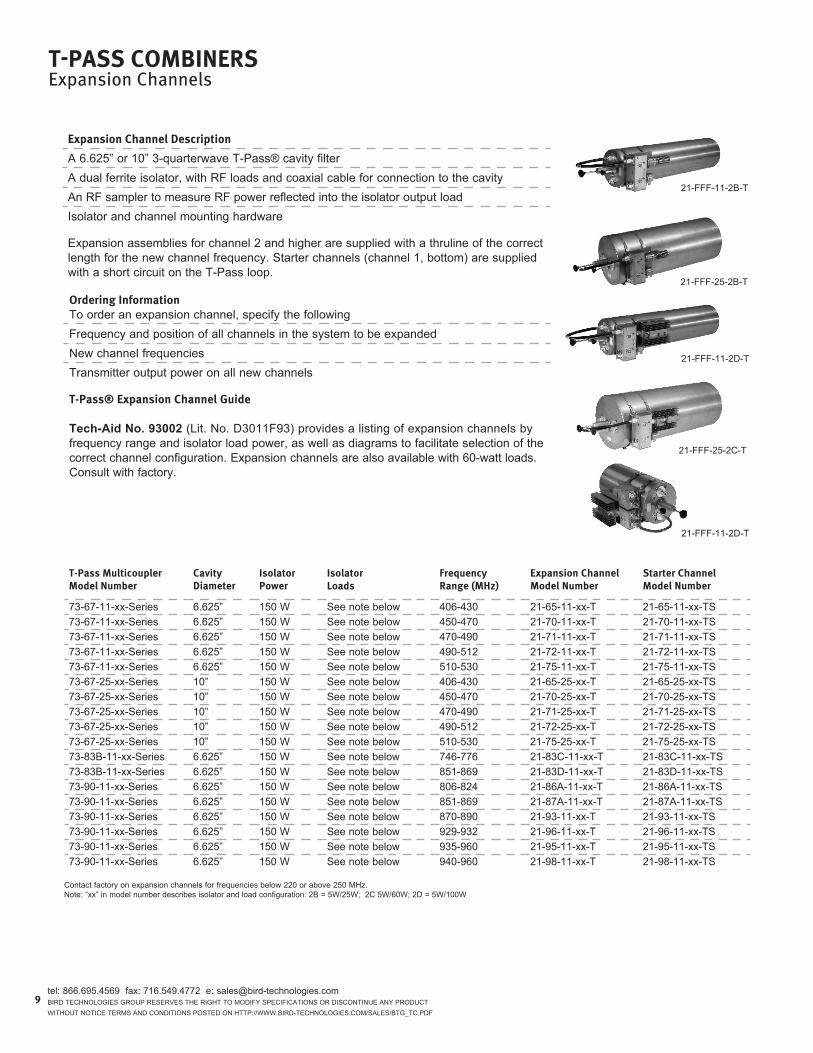
73-67-11-xx-series 6.625” 150 W see note below 406-430 21-65-11-xx-T 21-65-11-xx-Ts73-67-11-xx-series 6.625” 150 W see note below 450-470 21-70-11-xx-T 21-70-11-xx-Ts73-67-11-xx-series 6.625” 150 W see note below 470-490 21-71-11-xx-T 21-71-11-xx-Ts73-67-11-xx-series 6.625” 150 W see note below 490-512 21-72-11-xx-T 21-72-11-xx-Ts73-67-11-xx-series 6.625” 150 W see note below 510-530 21-75-11-xx-T 21-75-11-xx-Ts73-67-25-xx-series 10” 150 W see note below 406-430 21-65-25-xx-T 21-65-25-xx-Ts73-67-25-xx-series 10” 150 W see note below 450-470 21-70-25-xx-T 21-70-25-xx-Ts73-67-25-xx-series 10” 150 W see note below 470-490 21-71-25-xx-T 21-71-25-xx-Ts73-67-25-xx-series 10” 150 W see note below 490-512 21-72-25-xx-T 21-72-25-xx-Ts73-67-25-xx-series 10” 150 W see note below 510-530 21-75-25-xx-T 21-75-25-xx-Ts73-83B-11-xx-series 6.625” 150 W see note below 746-776 21-83c-11-xx-T 21-83c-11-xx-Ts73-83B-11-xx-series 6.625” 150 W see note below 851-869 21-83d-11-xx-T 21-83d-11-xx-Ts73-90-11-xx-series 6.625” 150 W see note below 806-824 21-86A-11-xx-T 21-86A-11-xx-Ts73-90-11-xx-series 6.625” 150 W see note below 851-869 21-87A-11-xx-T 21-87A-11-xx-Ts73-90-11-xx-series 6.625” 150 W see note below 870-890 21-93-11-xx-T 21-93-11-xx-Ts73-90-11-xx-series 6.625” 150 W see note below 929-932 21-96-11-xx-T 21-96-11-xx-Ts73-90-11-xx-series 6.625” 150 W see note below 935-960 21-95-11-xx-T 21-95-11-xx-Ts73-90-11-xx-series 6.625” 150 W see note below 940-960 21-98-11-xx-T 21-98-11-xx-Ts
contact factory on expansion channels for frequencies below 220 or above 250 Mhz.note: “xx” in model number describes isolator and load configuration: 2B = 5W/25W; 2c 5W/60W; 2d = 5W/100W
tel: 866.695.4569 fax: 716.549.4772 e: [email protected] Technologies group reserVes The righT To ModiFY speciFicATions or disconTinue AnY producT WiThouT noTice TerMs And condiTions posTed on hTTp://WWW.Bird-Technologies.coM/sAles/BTg_Tc.pdF
9
expansion Channel Description
A 6.625” or 10” 3-quarterwave T-pass® cavity filterA dual ferrite isolator, with rF loads and coaxial cable for connection to the cavityAn rF sampler to measure rF power reflected into the isolator output loadisolator and channel mounting hardware
expansion assemblies for channel 2 and higher are supplied with a thruline of the correct length for the new channel frequency. starter channels (channel 1, bottom) are supplied with a short circuit on the T-pass loop.
ordering information To order an expansion channel, specify the followingFrequency and position of all channels in the system to be expandednew channel frequenciesTransmitter output power on all new channels
T-Pass® expansion Channel Guide
Tech-Aid No. 93002 (lit. no. d3011F93) provides a listing of expansion channels by frequency range and isolator load power, as well as diagrams to facilitate selection of the correct channel configuration. expansion channels are also available with 60-watt loads. consult with factory.

T-Pass CombinersRacks
1
1 4
23
dido W
h
number Dimensions CaViTies freQ banD Paired 19” adaptorsDi (in) Do (in) W (in) H (in) no. Dia. (in)
93-00-01* 26.19 28.69 24.00 79.50 13 10 VhF, uhF(3/4 l cavity) 91-00-7393-00-02* 13.31 15.81 24.00 65.25 15 6.625 746-960 Mhz 91-00-54 or -9993-00-04* 11.69 14.19 24.00 65.25 15 6.625 uhF (1/4 l cavity) 91-00-6193-00-06 11.69 14.19 24.00 86.50 21 6.625 uhF (1/4 l cavity) 91-00-6193-00-08* 26.19 28.69 24.00 86.50 21 6.625 VhF, uhF(3/4 l cavity) 91-00-7393-00-09* 26.19 28.69 24.00 65.25 15 6.625 VhF, uhF(3/4 l cavity) 91-00-7393-00-10* 13.31 15.81 24.00 86.50 21 6.625 746-960 Mhz 91-00-54 or -9993-00-11* 26.19 28.69 24.00 109.25 19 10 VhF, uhF(3/4 l cavity) 91-00-7393-00-13 20.19 22.69 24.00 86.50 21 6.625 806-960 Mhz (5/4 l cavity) 91-00-7893-00-14* 50.90 53.40 24.00 79.50 13 10 66-88 Mhz consult factory93-00-17 20.70 23.20 24.00 65.25 15 6.625 806-869 Mhz (5/4 l cavity) 91-00-7893-00-18* 31.70 34.20 24.00 65.25 15 6.625 118-136 Mhz consult factory93-00-19* 33.70 36.20 24.00 79.50 13 10 118-136 Mhz consult factory93-00-21* 19.20 21.70 24.00 79.50 13 10 220-300 Mhz 91-00-10793-00-22* 14.20 16.70 24.00 86.50 21 6.625 746-869 Mhz, 300-400 Mhz 91-00-10093-00-23* 27.69 30.19 24.00 86.50 21 6.625 380-420 Mhz 91-00-10593-00-24* 14.20 16.70 24.00 65.25 15 6.625 746-869 Mhz, 300-400 Mhz 91-00-10093-00-25* 27.80 30.30 24.00 65.25 15 6.625 380-420 Mhz 91-00-10593-00-26 27.00 30.00 24.00 65.25 12 8 VhF, uhF(3/4 l cavity) 91-00-10693-00-27 27.00 30.00 24.00 79.25 16 8 VhF, uhF(3/4 l cavity) 91-00-10693-00-28# 26.19 28.69 24.00 75.75 18 6.625 VhF, uhF(3/4 l cavity) 91-00-7393-00-29# 26.19 28.69 24.00 75.75 12 10 VhF, uhF(3/4 l cavity) 91-00-7393-00-97509 26.19 28.69 24.00 92.50 24 6.625 VhF, uhF(3/4 l cavity) 91-00-7393-00-00042 26.19 28.69 24.00 65.25 10 10 VhF, uhF(3/4 l cavity) 91-00-7393-00-02453 13.31 15.81 24.00 47.00 6 6.625 746-960 Mhz 91-00-54 or -99
noTes:1. Models with * can also be ordered with reduced number of pegs. Add -lp at the end of the model number. peg Kits 91-00-peg, 91-00-peg1, 91-00-peg2 available for system expansion. consult factory for kit selection.2. 19” adaptors may increase rack height and width, or reduce the max number of cavities for those racks. please consult factory.3. Models with # are for use in 93-00-30 locking cabinet with doors.
tel: 866.695.4569 fax: 716.549.4772 e: [email protected] Technologies group reserVes The righT To ModiFY speciFicATions or disconTinue AnY producT
WiThouT noTice TerMs And condiTions posTed on hTTp://WWW.Bird-Technologies.coM/sAles/BTg_Tc.pdF
10
Bird Technologies group, TX rX systems brand, T-pass racks provide a simple and secure mounting for our expandable cavity multicoupler systems. They are constructed of alodined aluminum except for the steel gussets and cavity support pegs. shipment is usually made in six sub-assemblies and completed on site. racks under 66” in height can be shipped ups. Various rack models are required to accommodate the dif-ferent cavity diameters and resonator lengths. The chart below provides the principle dimensions for space and mounting considerations.
depending on the frequency band, the tuning rods will extend beyond 9” ~ 12” beyond one of the uprights. For clearance consideration, use do + 12” for the overall depth.
Aluminum channel 3” x 1” x .125” wallsolid aluminum bar 1.25” x 1.5”Triangular steel gusset 9” x 9”spare open circuited stub for 800 Mhz system, all others are short circuits

* X at the end of model number indicates number of channels: 2~6 channels
sTar JunCTion Combiners/mulTiCouPlersVHF Airband 118-137 MHz
Passbands for a 3-channel System
Am
plitu
de (d
B)
Frequency (MHz)
Am
plitu
de (d
B)
Passband for One Channel
Frequency (MHz)
tel: 866.695.4569 fax: 716.549.4772 e: [email protected] Technologies group reserVes The righT To ModiFY speciFicATions or disconTinue AnY producT WiThouT noTice TerMs And condiTions posTed on hTTp://WWW.Bird-Technologies.coM/sAles/BTg_Tc.pdF
11
CaViTy reCeiVe mulTiCouPlermodel numbers 42-35A-02094-X
42-35A-02280-X
Cavity size 8” (203 mm) diameter
number of Cavities Per Channel
42-35A-02094-X42-35A-02280-X
12
Cavity tuning range 118-137 Mhz
minimum Channel separation
200 khz
Cavity insertion loss
0.9 dB
maximum Channel insertion loss (When configured as a combiner or multicoupler)
42-35A-02094-X42-35A-02280-X
2.0 dB2.5 dB
isolator insertion loss
n/A
isolation, channel to channel
n/A
isolation, antenna to Transmitter
n/A
maximum Power per channel (at minimum channel separation)
rX only
maximum Power per channel (at wider channel separation)
rX only
CaViTy TransmiT Combinermodel numbers 42-35A-02093-X
42-35A-02279-X
Cavity size 8” (203 mm) diameter
number of Cavities Per Channel
42-35A-02093-X42-35A-02279-X
12
Cavity tuning range 118-137 Mhz
minimum Channel separation
200 khz
Cavity insertion loss
0.9 dB
maximum Channel insertion loss (When configured as a combiner or multicoupler)
42-35A-02093-X42-35A-02279-X
2.5 dB3.0 dB
isolator insertion loss
0.5 dB
isolation, channel to channel
42-35A-02093-X42-35A-02279-X
30 dB35 dB
isolation, antenna to Transmitter
25 dB
maximum Power per channel (at minimum channel separation)
50 W
maximum Power per channel (at wider channel separation)
80 W typical

sTar JunCTion Combiners/mulTiCouPlers UHF Airband
225-400 MHz
Cavity Response Curves
Frequency (MHz)
Am
plitu
de (d
B)
* X at the end of model number indicates number of channels
tel: 866.695.4569 fax: 716.549.4772 e: [email protected] Technologies group reserVes The righT To ModiFY speciFicATions or disconTinue AnY producT
WiThouT noTice TerMs And condiTions posTed on hTTp://WWW.Bird-Technologies.coM/sAles/BTg_Tc.pdF
12
CaViTy reCeiVe mulTiCouPlermodel numbers 42-53A-04782-X
42-53A-04786-X
Cavity size 8” (203 mm) diameter
number of Cavities Per Channel
42-53A-04782-X42-53A-04786-X
12
Cavity tuning range 225-400 Mhz
minimum Channel separation
1 Mhz
Cavity insertion loss
0.5-0.7 dB
maximum Channel insertion loss (When configured as a combiner or multicoupler)
42-53A-04782-X42-53A-04786-X
1.0 dB1.5 dB
isolator insertion loss
n/A
isolation, channel to channel
n/A
isolation, antenna to Transmitter
n/A
maximum Power per channel (at minimum channel separation)
rX only
CaViTy TransmiT Combinermodel numbers 44-53-04783-X
42-53-04787-X
Cavity size 8” diameter
number of Cavities Per Channel
44-53-04783-X42-53-04787-X
12
Cavity tuning range 225-400 Mhz
minimum Channel separation
44-53-04783-X42-53-04787-X
1 Mhz275 khz
Cavity insertion loss
0.5-0.7 dB
maximum Channel insertion loss (When configured as a combiner or multicoupler)
44-53-04783-X42-53-04787-X
2.0 dB3.0 dB
isolator insertion loss
1.0 dB
isolation, channel to channel
44-53-04783-X42-53-04787-X
22 dB27 dB
isolation, antenna to Transmitter
17 dB
maximum Power per channel (at minimum channel separation)
100 W
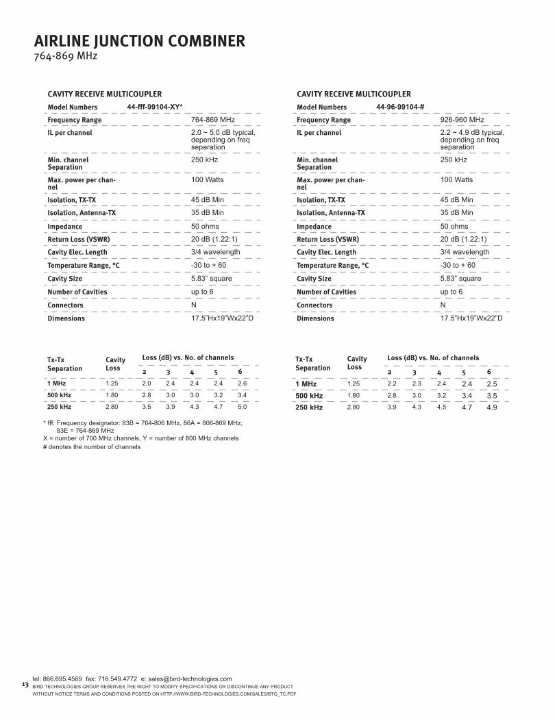
airline JunCTion Combiner764-869 MHz
Tx-Tx separation
Cavity loss
loss (db) vs. no. of channels
2 3 4 5 61 MHz 1.25 2.0 2.4 2.4 2.4 2.6
500 kHz 1.80 2.8 3.0 3.0 3.2 3.4
250 kHz 2.80 3.5 3.9 4.3 4.7 5.0
Tx-Tx separation
Cavity loss
loss (db) vs. no. of channels
2 3 4 5 6
1 MHz 1.25 2.2 2.3 2.4 2.4 2.5500 kHz 1.80 2.8 3.0 3.2 3.4 3.5250 kHz 2.80 3.9 4.3 4.5 4.7 4.9
* fff: Frequency designator: 83B = 764-806 Mhz, 86A = 806-869 Mhz, 83e = 764-869 MhzX = number of 700 Mhz channels, Y = number of 800 Mhz channels# denotes the number of channels
tel: 866.695.4569 fax: 716.549.4772 e: [email protected] Technologies group reserVes The righT To ModiFY speciFicATions or disconTinue AnY producT WiThouT noTice TerMs And condiTions posTed on hTTp://WWW.Bird-Technologies.coM/sAles/BTg_Tc.pdF
13
CaViTy reCeiVe mulTiCouPlermodel numbers 44-fff-99104-XY*
frequency range 764-869 Mhz
il per channel 2.0 ~ 5.0 dB typical, depending on freq separation
min. channel separation
250 khz
max. power per chan-nel
100 Watts
isolation, TX-TX 45 dB Min
isolation, antenna-TX 35 dB Min
impedance 50 ohms
return loss (VsWr) 20 dB (1.22:1)
Cavity elec. length 3/4 wavelength
Temperature range, °C -30 to + 60
Cavity size 5.83” square
number of Cavities up to 6
Connectors n
Dimensions 17.5”hx19”Wx22”d
CaViTy reCeiVe mulTiCouPlermodel numbers 44-96-99104-#
frequency range 926-960 Mhz
il per channel 2.2 ~ 4.9 dB typical, depending on freq separation
min. channel separation
250 khz
max. power per chan-nel
100 Watts
isolation, TX-TX 45 dB Min
isolation, antenna-TX 35 dB Min
impedance 50 ohms
return loss (VsWr) 20 dB (1.22:1)
Cavity elec. length 3/4 wavelength
Temperature range, °C -30 to + 60
Cavity size 5.83” square
number of Cavities up to 6
Connectors n
Dimensions 17.5”hx19”Wx22”d

tel: 866.695.4569 fax: 716.549.4772 e: [email protected] Technologies group reserVes The righT To ModiFY speciFicATions or disconTinue AnY producT
WiThouT noTice TerMs And condiTions posTed on hTTp://WWW.Bird-Technologies.coM/sAles/BTg_Tc.pdF
14
ComPaCT CeramiC CombinersStandard Models
450-512 MHz
sinGle CaViTy sPeCifiCaTions
frequency range 450-512 Mhz
maximum Power per channel 110 W typical, 125 W max
Cavity input return loss 20 dB typical, 18 dB min
input / output Connector n(F)
operating Temperature -10°c to + 55°c
storage Temperature -40°c to + 95°c
size 5.82” x 5.82” x 17 (including tuning rod)
TyPiCal 6 CHannel TransmiT Combiner sPeCifiCaTions
frequency range 450-512 Mhz
insertion loss (150 kHz spacing) 3.7 dB typical, 5.3 dB max.
insertion loss (250 kHz spacing)
2.9 dB typical, 4.8 dB max.
insertion loss (500 kHz spacing) 2.4 dB typical, 4.3 dB max.
Tx to Tx isolation >65 dB
input VsWr 1.2:1 maximum
average input Power per Channel (continuous duty)
110W typical, 125 W max
number of Cavities 6
Height (inches) 17” (9-10 rack units)
Depth (inches) 17”
Width (inches) 18”
19” rack mountable Yes
Weight (lbs) Approximately 100 lbs.
input / output Connector n(F)
operating Temperature -30° c to +55° c
storage Temperature -40° c to +95° c
selectivity (T-pass configuration)
Frequency Mhz
loss
es (d
B)
selectivity (T-pass configuration)
Frequency Mhz
loss
es (d
B)
Model numbers will be determined based on frequency plan.please consult factory.
Bird Technologies group, TX rX systems brand, uhF ceramic TX com-biner combines up to 6 transmitters onto a single antenna. With a footprint that’s more than 50% smaller than comparably performing 10” cavities. This optimizes valuable space for your radio equipment, which in an era of esca-lating lease costs, makes it the perfect solution for expansion. And because of our modular design, you can purchase in single-channel increments. plus, it delivers the kind of high performance and minimum interference you’ve come to expect from Bird®.
Any communications system installation where you need to reduce the num-ber of antennas on a towerAny communications system designed to minimize tower size and maximize site spacesecured applications that require equipment under lock and key

tel: 866.695.4569 fax: 716.549.4772 e: [email protected] Technologies group reserVes The righT To ModiFY speciFicATions or disconTinue AnY producT WiThouT noTice TerMs And condiTions posTed on hTTp://WWW.Bird-Technologies.coM/sAles/BTg_Tc.pdF
15
Bird Technologies group, TX rX systems brand, short-haul control station combiners provide fixed isolation between radio units using power attenuators and signal-combining techniques. The result is a constant isolation between radios regardless of the frequen-cies. Additionally, the higher per channel insertion losses resulted from the use of attenu-ators protect the receivers at the base site and the control stations from being overloaded by the transmitters in close proximity. These capabilities can significantly reduce tower clutter and loading, and simplify cabling installation at control center facilities.
Because these short-haul control station combiners are specifically designed with higher insertion losses for applications where the control stations and the base sites are less than 5 miles away, careful link budget analysis need to be conducted to verify signal strength and availability before the selection of these short-haul models.
Models are available in the 132-174 Mhz, 380-520 Mhz and 746-960 Mhz bands, in standard configurations of 4, 8, 16, 24 and 32 channel capacities. other frequency bands and higher channel capacities are also available upon request.
short-Haul models132-960 MHz
standard models132-869 MHz
Bird Technologies group, TX rX systems brand, multi-channel combiners provide frequency-agile operation across their entire frequency range. control station combiners may be used to reduce the number of antennas required on a communications site while also ensuring that predictable radio-to-radio isolation is maintained at all times - irrespec-tive of individual radio’s Tx or rx operating mode or antenna isolation characteristics.
single antenna-port mobiles may be connected to these combiners to provide operation on two-antenna configurations (one Tx and one rx), or through a duplexer to a single antenna (i.e. Tx/rx). These capabilities can significantly reduce tower clutter and loading, and simplify cabling installation at control center facilities.
Models are available in the 132-150Mhz, 150-174Mhz, 380-450Mhz , 450-520 Mhz, and 746-869 Mhz, bands in standard configurations for 4, 8, 12, 16, and 32 capacities. other frequency bands and higher channel capacities are also available upon request.
optional Duplexer for standard CsC
optional duplexers are available in uhF, 700, and 800 Mhz bands, (including a tri-band duplexer covering both the 700 and 800 Mhz bands), to be used in conjunction with the control station combiners. please consult factory for technical details.
ConTrol sTaTion Combiners
low profile for space efficient installationFrequency Agile with predictable isolationAnalog and digital compatibleAll passive components lead to superior reliabilityhybrid coupler technology with no need for tuning

ConTrol sTaTion CombinersStandard Models
132-869 MHz
meCHaniCalfinish BlackDimensionsmm/inches
h see table belowW 483 / 19d 420 / 16.5
Weight** see table belowConnectors n female
* Applications with higher duty cycles may require cooling fan option. contact factory for more info.
**cAuTion: The control station combiner is designed for rack mounting. due to the weight of the individual units rear support is required for each. A pair of 1/4 x 20” threaded inserts (one on each side of each unit) are provided for this purpose.
model numbers Description insertion loss Height net Weight 43-36-01-04 132-150 Mhz, 4 channel 7.5dB 1ru 22 lbs 43-36-01-08 132-150 Mhz, 8 channel 11dB 3ru 57 lbs 43-36-01-12 132-150 Mhz, 12 channel 14dB 4ru 79 lbs 43-36-01-16 132-150 Mhz, 16 channel 14dB 5ru 101 lbs 43-36-01-32 132-150 Mhz, 32 channel 18dB 11ru 216 lbs 43-37a-01-04 150-174 Mhz, 4 channel 7.5dB 1ru 22 lbs 43-37a-01-08 150-174 Mhz, 8 channel 11dB 3ru 57 lbs 43-37a-01-12 150-174 Mhz, 12 channel 14dB 4ru 79 lbs 43-37a-01-16 150-174 Mhz, 16 channel 14dB 5ru 101 lbs 43-37a-01-32 150-174 Mhz, 32 channel 18dB 11ru 216 lbs 43-57a-01-04 380-450 Mhz, 4 channel 7dB 1ru 22 lbs 43-57a-01-08 380-450 Mhz, 8 channel 11dB 3ru 57 lbs 43-57a-01-12 380-450 Mhz, 12 channel 14dB 4ru 79 lbs 43-57a-01-16 380-450 Mhz, 16 channel 14dB 5ru 101 lbs 43-57a-01-32 380-450 Mhz, 32 channel 17dB 11ru 216 lbs 43-57b-01-04 450-520 Mhz, 4 channel 7dB 1ru 22 lbs 43-57b-01-08 450-520 Mhz, 8 channel 11dB 3ru 57 lbs 43-57b-01-12 450-520 Mhz, 12 channel 14dB 4ru 79 lbs 43-57b-01-16 450-520 Mhz, 16 channel 14dB 5ru 101 lbs 43-57b-01-32 450-520 Mhz, 32 channel 17dB 11ru 216 lbs 43-83G-01-04 746-869 Mhz, 4 channel 8dB 1ru 20 lbs 43-83G-01-08 746-869 Mhz, 8 channel 11.5dB 1ru 22 lbs 43-83G-01-12 746-869 Mhz, 12 channel 15dB 3ru 58 lbs 43-83G-01-16 746-869 Mhz, 16 channel 15dB 3ru 57 lbs 43-83G-01-24 746-869 Mhz, 24 channel 15dB 4ru 79 lbs 43-83G-01-32 746-869 Mhz, 32 channel 18.5dB 5ru 101 lbs
tel: 866.695.4569 fax: 716.549.4772 e: [email protected] Technologies group reserVes The righT To ModiFY speciFicATions or disconTinue AnY producT
WiThouT noTice TerMs And condiTions posTed on hTTp://WWW.Bird-Technologies.coM/sAles/BTg_Tc.pdF
16
eleCTriCalfrequency range 132-150
150-174380-450746-869
rf Power W Txrx
per channel: 50 (50% duty cycle max)* per channel: <150 (intermittent)n/A
minimum frequency separation mHz
no limitation for adjacent channel separation. consult factory for minimum Tx-rx separation.
loss db see table below
isolation db Txrx
TX-Tx: 60 min, 70 typ; Ant - Tx: 60 min, 70 typTx-rx: 60 min, 70 typ: rx - rx: 60 min, 70 typ
return loss db >15
operating Temperature C° -10 ~ +50

tel: 866.695.4569 fax: 716.549.4772 e: [email protected] Technologies group reserVes The righT To ModiFY speciFicATions or disconTinue AnY producT WiThouT noTice TerMs And condiTions posTed on hTTp://WWW.Bird-Technologies.coM/sAles/BTg_Tc.pdF
17
ConTrol sTaTion Combiners
reCommenDeD oPTions: DuPleXersmodel numbers/frequency range
26-83B-10A
26-83G-10A
26-89-A-10A
762-776 Mhz792-806 Mhz762-776 Mhz792-824 Mhz851-869 Mhz806-824 Mhz851-869 Mhz
rf Power W 26-83B-10A26-83G-10A
26-89-A-10A
1414321818
isolation loss (db), max. 1.5
ripple in band (db), max. 0.8
rejection (db), min. 70 between T/r
isolation (db), min. 26-83B-10A26-83G-10A26-89-A-10A
807080
return loss (db), min. 26-83B-10A26-83G-10A26-89-A-10A
201820
impedance (W) 50 ohms
Connector n-Female
Power rating (W) 26-83B-10A26-83G-10A26-89-A-10A
10050100
Temperature range, °C -20 ~ + 70
size (in/mm)* 26-83B-10A26-83G-10A26-89-A-10A
8.0 (204)x6.0(153)x1.4(36)10.1(257)x8.2(207)x1.7(44)8.0 (204)x6.0(153)x1.4(36)

mulTibanD sHourTHaul ConTrol sTaTion Combiner43-05-01 series
mulTibanD sPeCifiCaTionsfrequency range 30-180 Mhz
330-520 Mhz746-960 Mhz
isolation loss 0.5 dB typ. (1 dB max.)
sub-band Port-Port isola-tion
>40 dB
T/r Port return loss >14 dB
anT Port return loss >14 dB
Power rating 30 watts continuous
Temperature -30 to +60 deg c
rf Connector n-Female
environment ip67 subject to sealing of connectors terminations
mounting suitable for pole, Wall or cable Tray Mount (hoseclamp and/or screws not included)
size 7.2 x 1.2 x 5 in / 182 x 30 x 127 mm
Weight 2.9 lbs / 1.3 kgs typ.
BTg, TX rX system brand Multiband coupler allows multiband operation of tower transmission lines.
BTg, TX rX system brand multi-channel multi-band combiners provide frequency-agile operation across multiple bands. interoperability can be combined into a single network for efficiency.
mulTibanD sHourTHaul sPeCifiCaToinsfrequency range 40-960 Mhz
Channel Capacity 43-05-01-08-SH43-05-01-16-SH
1-8 channels9-16 channels
isolation loss 43-05-01-08-SH
43-05-01-16-SH
30.5 dB +/-1 dB typ. @ 380 Mhz32.5 dB +/-1 dB typ. @ 960 Mhz34 dB +/-1 dB typ. @ 380 Mhz36.5 dB max @ 960 Mhz
T/r Port-Port isolation 60 dB typ.
anT Port -T/r Port isolation
43-05-01-08-SH43-05-01-16-SH
30 dB typ.34 dB typ.
T/r Port return loss >20 dB
anT Port return loss >14 dB
Power rating up to 50 watts continuous
Duty Cycle see note Below20% @ 50 watts continuous on all ports40% @ 25 watts continuous on all ports100% @ 10 watts continuous on all ports
Temperature -30 to +60 °c
size 43-05-01-08-SH43-05-01-16-SH
19x1.75x8 in / 483x44.75x203 mm19x3.5x8 in / 483x89.5x203 mm (note: not including connectors)
Grounding M6 grounding stud
Weight 13.2 lbs/6 kgs typ.
mulTibanD CouPler80-05-14
tel: 866.695.4569 fax: 716.549.4772 e: [email protected] Technologies group reserVes The righT To ModiFY speciFicATions or disconTinue AnY producT
WiThouT noTice TerMs And condiTions posTed on hTTp://WWW.Bird-Technologies.coM/sAles/BTg_Tc.pdF
18

tel: 866.695.4569 fax: 716.549.4772 e: [email protected] Technologies group reserVes The righT To ModiFY speciFicATions or disconTinue AnY producT WiThouT noTice TerMs And condiTions posTed on hTTp://WWW.Bird-Technologies.coM/sAles/BTg_Tc.pdF
referenCePower Conversion Chart
PoWer ConVersion CHarT Dbm To DbW To WaTTs To VolTsdBm dBw Watts Volts (50 ohm)80 50 100 kW 223675 45 31.6 kW 125770 40 10.0 kW 70765 35 3.16 kW 39860 30 1000 22455 25 316 12650 20 100 70.745 15 31.6 39.840 10 10.0 22.438 8 6.31 17.836 6 3.98 14.134 4 2.51 11.232 2 1.58 8.9030 0 1.00 7.0729 -1 0.79 6.3028 -2 0.63 5.6227 -3 0.50 5.0126 -4 0.40 4.4625 -5 0.32 3.9824 -6 0.25 3.5423 -7 0.20 3.1622 -8 0.16 2.8221 -9 0.13 2.5120 -10 0.10 2.2419 -11 79 mW 1.99
PoWer ConVersion CHarT Dbm To DbW To WaTTs To VolTsdBm dBm Watts Volts (50 ohm)18 -12 63 mW 1.7817 -13 50 mW 1.5816 -14 40 mW 1.4115 -15 32 mW 1.2614 -16 25 mW 1.1213 -17 20 mW 1.0012 -18 16 mW 0.89011 -19 13 mW 0.79310 -20 10 mW 0.7079 -21 7.9 mW 0.6308 -22 6.3 mW 0.5627 -23 5.0 mW 0.5016 -24 4.0 mW 0.4465 -25 3.2 mW 0.3984 -26 2.5 mW 0.3543 -27 2.0 mW 0.3162 -28 1.6 mW 0.2821 -29 1.3 mW 0.2510 -30 1.0 mW 0.224-5 -35 316 uW 0.126-10 -40 100 uW 0.071-15 -45 31.6 uW 0.040-20 -50 10 uW 0.022-25 -55 3.16 uW 0.013-30 -60 1 uW 0.007
19

tel: 866.695.4569 fax: 716.549.4772 e: [email protected] Technologies group reserVes The righT To ModiFY speciFicATions or disconTinue AnY producT
WiThouT noTice TerMs And condiTions posTed on hTTp://WWW.Bird-Technologies.coM/sAles/BTg_Tc.pdF
PaTH lenGTH(miles)
PaTH loss in Db: freQuenCy in mHz
50 150 170 450 500 800 9000.1 50.58 60.12 61.21 69.66 70.58 74.66 75.68
0.25 58.54 68.08 69.17 77.62 78.54 82.62 83.64
0.5 64.56 74.10 75.19 83.64 84.56 88.64 89.66
1 70.58 80.12 81.21 89.66 90.58 94.66 95.68
2 76.60 86.14 87.23 95.68 96.60 100.68 101.71
3 80.12 89.66 90.75 99.21 100.12 104.20 105.23
4 82.62 92.16 93.25 101.71 102.62 106.70 107.73
5 84.56 94.10 95.19 103.64 104.56 108.64 109.66
6 86.14 95.68 96.77 105.23 106.14 110.22 111.25
7 87.48 97.02 98.11 106.57 107.48 111.56 112.59
8 88.64 98.18 99.27 107.73 108.64 112.72 113.75
9 89.66 99.21 100.29 108.75 109.66 113.75 114.77
10 90.58 100.12 101.21 109.66 110.58 114.66 115.68
12 92.16 101.71 102.79 111.25 112.16 116.25 117.27
14 93.50 103.04 104.13 112.59 113.50 117.58 118.61
16 94.66 104.20 105.29 113.75 114.66 118.74 119.77
18 95.68 105.23 106.31 114.77 115.68 119.77 120.79
20 96.60 106.14 107.23 115.68 116.60 120.68 121.71
30 100.12 109.66 110.75 119.21 120.12 124.20 125.23
40 102.62 112.16 113.25 121.71 122.62 126.70 127.73
50 104.56 114.10 115.19 123.64 124.56 128.64 129.66
free sPaCe PaTH loss esTimaTor
ForMulA: path loss (dB) = 36.6 + 20 log (Mhz) + 20 log (miles)
referenCeFree Space Path Lost
20

tel: 866.695.4569 fax: 716.549.4772 e: [email protected] Technologies group reserVes The righT To ModiFY speciFicATions or disconTinue AnY producT WiThouT noTice TerMs And condiTions posTed on hTTp://WWW.Bird-Technologies.coM/sAles/BTg_Tc.pdF
21

tel: 866.695.4569 fax: 716.549.4772 e: [email protected] Technologies group reserVes The righT To ModiFY speciFicATions or disconTinue AnY producT
WiThouT noTice TerMs And condiTions posTed on hTTp://WWW.Bird-Technologies.coM/sAles/BTg_Tc.pdF
22

Transmit CombinersYou’re heard, loud and clear.
Bird® Technologies Group (BTG) is a global, innovative supplier
of RF products, systems, services and educational solutions.
Combining the industry leading brands of both Bird Electronic
and TX RX Systems in one company reinforces the BTG
commitment to providing RF Measurement and Management in
Your World.
Our portfolio includes hardware, software, components and services. We
offer these innovative products and services through our industry lead-
ing product line brands, Bird Electronic Corp and TX RX Systems. We
provide test instruments that are highly accurate, rugged and easy to
use. Industry leading components and products such as site analyzers,
wattmeters, digital sensors, samplers, antennas, signal boosters,
and tower mounted amplifiers. Furthermore, we offer dependable
engineering, calibration and educational services for land mobile radio,
cellular, semiconductor, broadcast, medical, military and government
applications.
All BTG products can be serviced and calibrated by the Bird Service
Center (BSC). BSC provides a full range of service and support. With over
130 years of combined product and calibration experience, our service
technicians and product experts offer reliable service and customer care.
Bird Service Centers and Service Partners are located World Wide
providing a full range of service and support for your Bird Products.
Catalogs offered by Bird Technologies Group(To view or download go to www.bird-technologies.com)
Bird General Catalog
RF & Microwave Components Catalog
Transmit Combiners Catalog
Cavity Filters & Duplexers Catalog
Antennas Catalog
Tower Top Amplifiers, Receiver Multicouplers & Preselectors Catalog
Isolators & Loads Catalog
In-Building Coverage Catalog (Signal Boosters & Accessories)
Bird® Technologies Group combines the industry leading brands of both Bird Electronic and TX RX Systems and is a global, innovative supplier of RF products,systems, services and educational solutions. Bird® Technologies Group reserved the right to modify specifications or discontinue any product without notice.
You’re heard, loud and clear.
30303 Aurora Rd. :: Solon, OH 44139 :: 866.695.4569 :: www.bird-technologies.com
©2009 Bird Technologies GroupTransCom-10142009
Recommended