ISO 9001certified
TransilluminatedKnobs
expandedproduct line
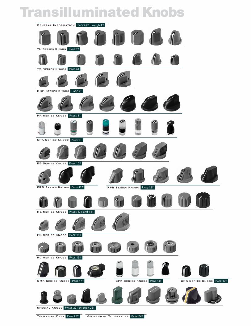
Transilluminated Knobs
TL Series Knobs PAGE 5T
TS Series Knobs PAGE 6T
PR Series Knobs PAGES 8T
General Information PAGES 2T through 4T
Technical Data PAGE 23T
RE Series Knobs PAGES 13T and 14T
\
Mechanical Tolerances PAGE 24T
\]
Special Knobs PAGES 20T through 22T
SPK Series Knobs PAGE 9T
DBP Series Knobs PAGE 7T
FRB Series Knobs PAGE 11T
CMK Series Knobs PAGE 17T CPK Series Knobs PAGE 18T CRK Series Knobs PAGE 19T
FPB Series Knobs PAGE 12T
PG Series Knobs PAGE 15T
PB Series Knobs PAGE 10T
RC Series Knobs PAGE 16T

2t
TransIlluminated Knobs
Illumination
General
Specifications
Electronic Hardware has been a manufacturer of transilluminated knobs for aircraft crew stationsand related equipment for over 40 years. We are QPL approved to MIL-K-25049 and manufactureour knobs in accordance with SAE-AS-7788, NASM3926, MIL-L-85762, NVIS Green A andNVIS Green B. We are a major supplier to airframe manufacturers and their avionics equipmentsuppliers. We also supply directly to the government and the FAA.Electronic Hardware Company’s total capability to manufacture transilluminated knobs to yourrequirements starts with a complete review of your requirements. Our in-house capabilitiesinclude engineering, mold design, tooling, fabrication, marking, finishing and light testing. Ourquality system is in accordance with MIL-1-45208 and certified to ISO 9001-2008. We have over25,000 square feet dedicated to knob manufacture. Our unique molding method provides lowcost tooling for your requirement. We utilize cellular manufacturing for assembly and finishingwhich provides superior quality and efficiency, and results in lower costs to you, our customer.The knobs shown are made to industry and or MIL standards. The shaft depth counter boredepth, diameter, set screw position, marking, and color can be altered by request.
Shall be shown as a percent of transmittance, defined as the percentage ratio of the brightnessof the marking to the brightness of the light source applied at the bottom of the knob.These readings are determined through the use of a light source which presents an evenly diffusedcircular lighted area. The shaft hole of the knob under test shall be plugged with an opaque materialand the knob shall be placed concentrically over the circle of light and shall overlap it by .06 inchon all sides.Light measurements shall be at five points along the index line, except over the metal insert onthe top of the knob.
Markings To enhance lighting and angle of visibility, knurling or flutes in the area of marking may beremoved. We utilize laser engraving, pad printing, and hot stamping to provide excellentdefinition of marking while maintaining cost effectiveness.
Plastic: Thermoplastic molding compound, clear for transilluminated knobs and colored fornon-illuminated knobs. The material used meets the requirements of SAE-AS-7788,MIL-L-85762, and NASM3926.
Inserts: Brass in accordance with QQ-B-626 (or equivalent).
Set Screws: Style to be NASM51021.
Finish: Knob Colors:White, Color Number 37875 per FED-STD-595 reflectance may be reduced to50% minimum. Markings shall meet daylight contrast of 9 minimum.Gray, Color Number 36231 per FED-STD-595.Black, Color Number 37038 per FED-STD-595.Other colors are available upon request.Bottom surface of illuminated knobs shall have no coating and shall be clear.
Inserts:Nickel plated per QQ-N-290, Grade G, Class 2.
Tolerances: Dimensions are in inches.Three-place decimal +–.010Two-place decimal +–.02Angles +–2º
Illumination: Unless specified, illumination ratio to be .05+–25%, ex.Type III NVIS
1
2
3
4
5
This illustration is the method we utilize in obtaining brightnessratios. A uniformly illuminated source set to a specific brightness infoot lamberts. Photometric measurements are taken at 5 equallyspaced locations along the marking, no readings are taken in thearea above the metal insert. The average of the measurements (1-5)is the percentage of the brightness of markings to the brightnessof the source. This is the brightness ratio, expressed as a decimal.
Electronic Hardware Corporation 1881 Lakeland Avenue, Ronkonkoma, NY 11779PHONE: 631.752.1950 FAX: 631.752.1971 WWW.ehcknobs.com EMAIL: [email protected] 1-800-752-1680
3t
TransIlluminatedGeneral Information
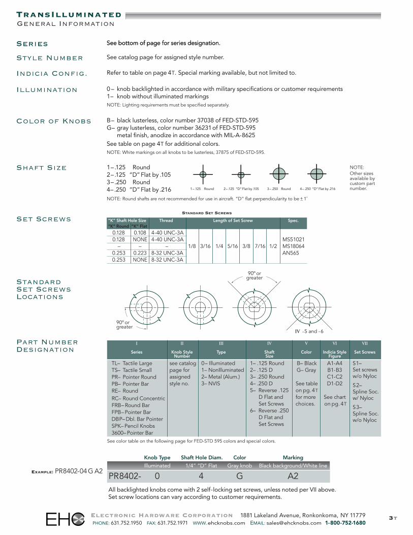
All backlighted knobs come with 2 self-locking set screws, unless noted per VII above.Set screw locations can vary according to customer requirements.
Knob Type Shaft Hole Diam. Color Marking
Illuminated 1/4” “D” Flat Gray knob Black background/White line
PR8402- 0 4 G A2EXAMPLE: PR8402-04GA2
Series See bottom of page for series designation.
Electronic Hardware Corporation 1881 Lakeland Avenue, Ronkonkoma, NY 11779PHONE: 631.752.1950 FAX: 631.752.1971 WWW.ehcknobs.com EMAIL: [email protected] 1-800-752-1680
STANDARD SET SCREWS
“K” Shaft Hole Size Thread Length of Set Screw Spec.“K” Round “K” Flat
0.128 0.108 4-40 UNC-3A0.128 NONE 4-40 UNC-3A MS51021– – – 1/8 3/16 1/4 5/16 3/8 7/16 1/2 MS18064
0.253 0.223 8-32 UNC-3A AN5650.253 NONE 8-32 UNC-3A
Set Screws
StandardSet ScrewsLocations
Shaft Size 1– .125 Round2– .125 “D”Flat by .1053– .250 Round4– .250 “D”Flat by .216 1–.125 Round 2– .125 “D”Flat by .105 3– .250 Round 4– .250 “D”Flat by .216
NOTE: Round shafts are not recommended for use in aircraft. “D” flat perpendicularity to be+_ 1˚
NOTE:Other sizesavailable bycustom partnumber.
See color table on the following page for FED-STD 595 colors and special colors.
90º orgreater
90ºorgreater
Illumination 0 – knob backlighted in accordance with military specifications or customer requirements1– knob without illuminated markingsNOTE: Lighting requirements must be specified separately.
Series See bottom of page for series designation.
Part NumberDesignation
Style Number See catalog page for assigned style number.
Indicia Config. Refer to table on page 4T. Special marking available, but not limited to.
Color of Knobs B– black lusterless, color number 37038 of FED-STD-595G– gray lusterless, color number 36231of FED-STD-595M– metal finish, anodize in accordance with MIL-A-8625See table on page 4T for additional colors.NOTE: White markings on all knobs to be lusterless, 37875 of FED-STD-595.
II III IV V VI
Knob Style Type Shaft Color Indicia StyleNumber Size Figure
see catalog 0– Illuminated 1– .125 Round B– Black A1-A4page for 1– NonIlluminated 2– .125 D G– Gray B1-B3assigned 2– Metal (Alum.) 3– .250 Round C1-C2style no. 3– NVIS 4– .250 D See table D1-D2
5– Reverse .125 on pg.4TD Flat and for more See chartSet Screws choices. on pg.4T
6– Reverse .250D Flat andSet Screws
VII
Set Screws
S1–Set screwsw/o Nyloc
S2–Spline Soc.w/ Nyloc
S3–Spline Soc.w/o Nyloc
I
Series
TL– Tactile LargeTS– Tactile SmallPR– Pointer RoundPB– Pointer BarRE– RoundRC– Round ConcentricFRB–Round BarFPB–Pointer BarDBP–Dbl. Bar PointerSPK–Pencil Knobs3600–Pointer Bar
IV -5 and -6
4t
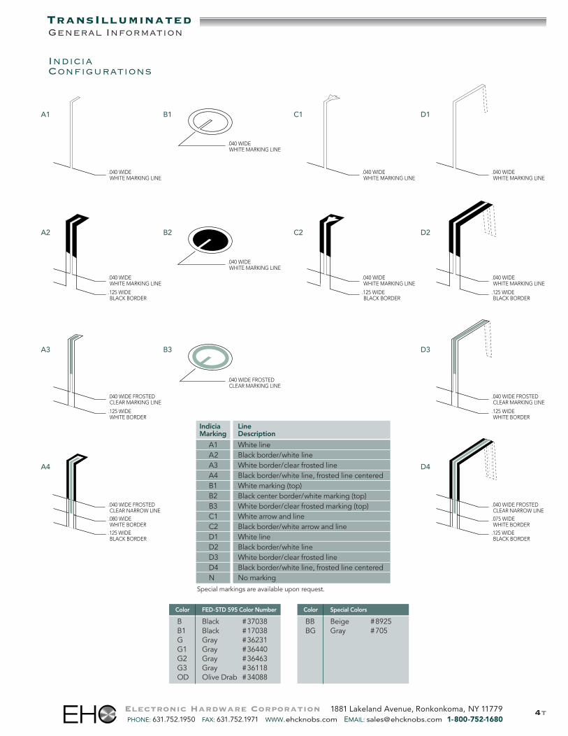
Color FED-STD 595 Color Number
B Black #37038B1 Black #17038G Gray #36231G1 Gray #36440G2 Gray #36463G3 Gray #36118OD Olive Drab #34088
Color Special Colors
BB Beige #8925BG Gray #705
TransIlluminatedGeneral Information
LineDescription
White lineBlack border/white lineWhite border/clear frosted lineBlack border/white line, frosted line centeredWhite marking (top)Black center border/white marking (top)White border/clear frosted marking (top)White arrow and lineBlack border/white arrow and lineWhite lineBlack border/white lineWhite border/clear frosted lineBlack border/white line, frosted line centeredNo marking
IndiciaMarking
A1A2A3A4B1B2B3C1C2D1D2D3D4N
.040 WIDEWHITE MARKING LINE
.040 WIDEWHITE MARKING LINE
.040 WIDE FROSTEDCLEAR MARKING LINE
.125 WIDE WHITE BORDER
.080 WIDEWHITE BORDER
.125 WIDEBLACK BORDER
.125 WIDEBLACK BORDER
.040 WIDE WHITE MARKING LINE
.040 WIDE WHITE MARKING LINE
.125 WIDEBLACK BORDER
.040 WIDEWHITE MARKING LINE
.040 WIDEWHITE MARKING LINE
.040 WIDE FROSTED CLEAR MARKING LINE
.040 WIDE FROSTEDCLEAR NARROW LINE
.040 WIDE WHITE MARKING LINE
.040 WIDE WHITE MARKING LINE
.040 WIDE FROSTED CLEAR MARKING LINE
.125 WIDE WHITE BORDER
.075 WIDE WHITE BORDER.125 WIDE BLACK BORDER
.125 WIDE BLACK BORDER
.040 WIDE FROSTED CLEAR NARROW LINE
Special markings are available upon request.
A1
A2
A3
A4
D1
D2
D3
D4
B1
B2
B3
C1
C2
Electronic Hardware Corporation 1881 Lakeland Avenue, Ronkonkoma, NY 11779PHONE: 631.752.1950 FAX: 631.752.1971 WWW.ehcknobs.com EMAIL: [email protected] 1-800-752-1680
IndiciaConfigurations

5t
TransIlluminated
TL SeriesA B C D Set Screws
Nut NutBase Clearance Clearance
Diameter Height Diameter Depth 1/8 1/4
0.88 0.75 0.38 0.16 MS51021-102 MS51021-1320.88 0.75 0.38 0.16 MS51021-102 MS51021-1320.88 0.75 0.38 0.16 MS51021-102 MS51021-1320.88 0.75 0.38 0.16 MS51021-102 MS51021-1320.88 0.75 0.38 0.16 MS51021-102 MS51021-1320.88 0.75 0.38 0.16 MS51021-102 MS51021-1320.88 0.75 0.38 0.16 MS51021-102 MS51021-1320.88 0.75 0.38 0.16 MS51021-102 MS51021-132
Style Number
85018502850385048505850685078508
TL Series
Design Variations• Part 8507 is available with or without“Grip/Pull” serations on the sides• Set screw locations can vary• Markings and color can vary (see page4T)• Nut clearance depth and diameter can vary• See part number system for shaft hole
designationDetailed drawings are available for each style
Electronic Hardware Corporation 1881 Lakeland Avenue, Ronkonkoma, NY 11779PHONE: 631.752.1950 FAX: 631.752.1971 WWW.ehcknobs.com EMAIL: [email protected] 1-800-752-1680
All of our backlighted knobs can be manufactured for night vision use. Our night vision knobs meet NVIS “Green A”requirements.
8501MS21385Fig.1
8502MS21385Fig. 2
8503MS21385Fig. 3
8504MS21385Fig. 4
8505MS21385Fig.5
8506MS21385Fig. 6
8507MS21385Fig. 7
8508MS21385Fig. 8
6t
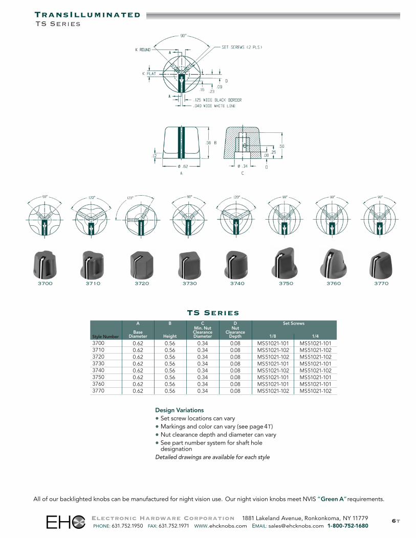
TS Series
37303700 37403710 3720 3750 3760 3770
Design Variations• Set screw locations can vary• Markings and color can vary (see page4T)• Nut clearance depth and diameter can vary• See part number system for shaft hole
designationDetailed drawings are available for each style
A B C D Set ScrewsMin. Nut Nut
Base Clearance ClearanceDiameter Height Diameter Depth 1/8 1/4
0.62 0.56 0.34 0.08 MS51021-101 MS51021-1010.62 0.56 0.34 0.08 MS51021-102 MS51021-1020.62 0.56 0.34 0.08 MS51021-102 MS51021-1020.62 0.56 0.34 0.08 MS51021-101 MS51021-1010.62 0.56 0.34 0.08 MS51021-102 MS51021-1020.62 0.56 0.34 0.08 MS51021-101 MS51021-1010.62 0.56 0.34 0.08 MS51021-101 MS51021-1010.62 0.56 0.34 0.08 MS51021-102 MS51021-102
Style Number
37003710372037303740375037603770
TransIlluminatedTS Series
Electronic Hardware Corporation 1881 Lakeland Avenue, Ronkonkoma, NY 11779PHONE: 631.752.1950 FAX: 631.752.1971 WWW.ehcknobs.com EMAIL: [email protected] 1-800-752-1680
All of our backlighted knobs can be manufactured for night vision use. Our night vision knobs meet NVIS “Green A”requirements.

7t
DBP SeriesA B C D E F G H L Set Screws
Nut Clearance Nut Clearance ShaftBase Diameter Depth Screw Hole
Diameter Height 1/8 1/4 Height Depth 1/8 1/4
0.81 0.56 0.26 – 0.10 0.25 0.50 0.28 0.50 0.88 MS51021-101 MS51021-1310.94 0.62 0.26 0.39 0.16 0.31 0.53 0.28 0.56 1.00 MS51021-101 MS51021-1311.06 0.69 0.26 0.39 0.16 0.31 0.59 0.32 0.62 1.12 MS51021-102 MS51021-1321.12 0.78 – 0.39 0.16 0.31 0.68 0.36 0.69 1.25 MS51021-102 MS51021-1321.38 0.88 – 0.39 0.16 0.31 0.78 0.38 0.75 1.50 MS51021-102 MS51021-133
Style Number
25802590260026102620
2600 262026102580 2590
Design Variations• Set screw locations can vary• Markings and color can vary (see page4T)• Nut clearance depth and diameter can vary• See part number system for shaft hole
designationDetailed drawings are available for each style
TransIlluminatedDBP Series
Electronic Hardware Corporation 1881 Lakeland Avenue, Ronkonkoma, NY 11779PHONE: 631.752.1950 FAX: 631.752.1971 WWW.ehcknobs.com EMAIL: [email protected] 1-800-752-1680
All of our backlighted knobs can be manufactured for night vision use. Our night vision knobs meet NVIS “Green A”requirements.
Drawings for style numbers2580, 2590, 2600, 2610,and 2620.
8tElectronic Hardware Corporation 1881 Lakeland Avenue, Ronkonkoma, NY 11779PHONE: 631.752.1950 FAX: 631.752.1971 WWW.ehcknobs.com EMAIL: [email protected] 1-800-752-1680
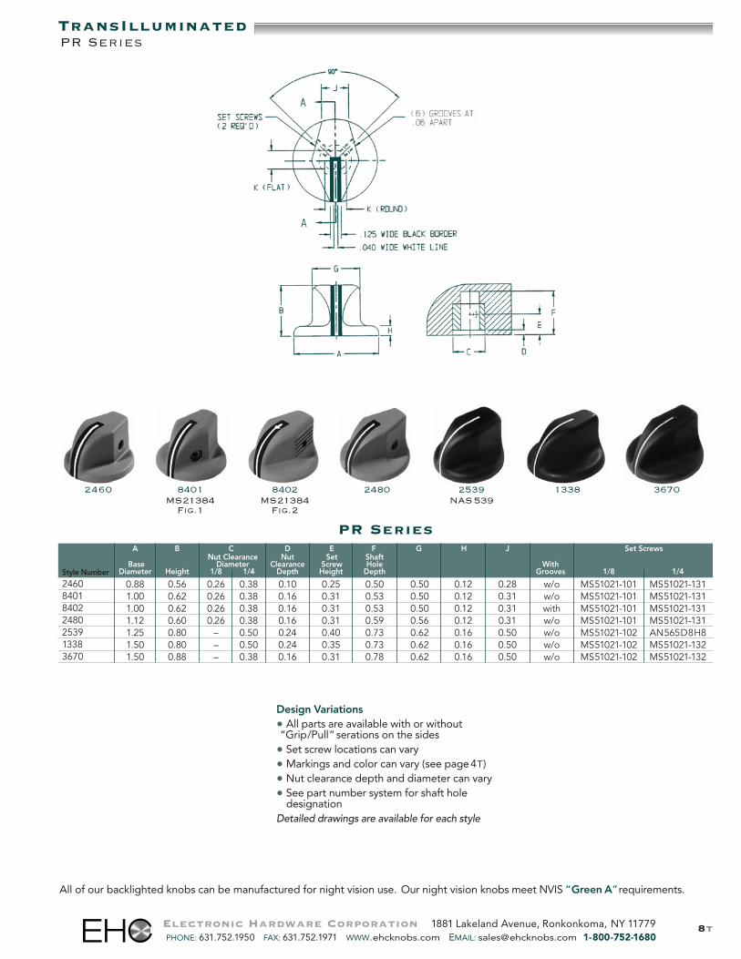
TransIlluminatedPR Series
All of our backlighted knobs can be manufactured for night vision use. Our night vision knobs meet NVIS “Green A”requirements.
2460 8401MS21384Fig.1
8402MS21384Fig.2
2480 2539NAS539
1338 3670
Design Variations• All parts are available with or without“Grip/Pull” serations on the sides• Set screw locations can vary• Markings and color can vary (see page4T)• Nut clearance depth and diameter can vary• See part number system for shaft hole
designationDetailed drawings are available for each style
PR SeriesA B C D E F G H J Set Screws
Nut Clearance Nut Set ShaftBase Diameter Clearance Screw Hole With
Diameter Height 1/8 1/4 Depth Height Depth Grooves 1/8 1/4
0.88 0.56 0.26 0.38 0.10 0.25 0.50 0.50 0.12 0.28 w/o MS51021-101 MS51021-1311.00 0.62 0.26 0.38 0.16 0.31 0.53 0.50 0.12 0.31 w/o MS51021-101 MS51021-1311.00 0.62 0.26 0.38 0.16 0.31 0.53 0.50 0.12 0.31 with MS51021-101 MS51021-1311.12 0.60 0.26 0.38 0.16 0.31 0.59 0.56 0.12 0.31 w/o MS51021-101 MS51021-1311.25 0.80 – 0.50 0.24 0.40 0.73 0.62 0.16 0.50 w/o MS51021-102 AN565D8H81.50 0.80 – 0.50 0.24 0.35 0.73 0.62 0.16 0.50 w/o MS51021-102 MS51021-1321.50 0.88 – 0.38 0.16 0.31 0.78 0.62 0.16 0.50 w/o MS51021-102 MS51021-132
Style Number
2460840184022480253913383670

9tElectronic Hardware Corporation 1881 Lakeland Avenue, Ronkonkoma, NY 11779PHONE: 631.752.1950 FAX: 631.752.1971 WWW.ehcknobs.com EMAIL: [email protected] 1-800-752-1680
TransIlluminatedSPK Series
All of our backlighted knobs can be manufactured for night vision use. Our night vision knobs meet NVIS “Green A”requirements.
Design Variations• Set screw sizes and locations can vary• Markings and color can vary according to• customer specifications• Multiple bands and colors are available• Multiple shaft diameters are available• with and without set screwsDetailed drawings are available for each style
7250 47906140 737 566 551 537691 4740 7510 6060
SPK SeriesA B E F
Set ShaftBase Screw Hole
Diameter Height Height Depth
0.36 0.88 w/o 0.510.37 0.57 0.28 0.520.38 0.65 0.34 0.540.38 0.88 0.13 0.210.38 0.88 0.30 0.500.38 0.88 0.12 0.610.39 0.63 w/o 0.320.39 0.73 w/o 0.420.40 0.68 0.15 0.620.40 1.03 0.50 0.680.46 0.76 0.23 0.59
Style Number
614073756655169147407250479053775106060

10t
PB Series
2270 470Fig.B
463Fig.B
8404MS21384Fig.4
8405 3674 3676
A B C D E F G H J Set ScrewsNut Clearance Nut Set Shaft
Base Diameter Clearance Screw Hole WithDiameter Height 1/8 1/4 Depth Height Depth Grooves 1/8 1/4
0.88 0.56 0.26 0.26 0.10 0.250 0.50 0.50 0.12 1.00 with MS51021-102 MS51021-1010.88 0.75 0.38 0.38 0.16 0.310 0.52 0.62 0.12 0.88 w/o MS51021-102 MS51021-1320.88 0.75 0.38 0.38 0.16 0.310 0.52 0.62 0.12 0.88 with MS51021-102 MS51021-1321.00 0.75 0.38 0.38 0.16 0.310 0.61 0.62 0.12 1.13 with MS51021-102 MS51021-1321.00 0.75 0.38 0.38 0.16 0.310 0.61 0.62 0.12 1.13 w/o MS51021-102 MS51021-1321.00 0.75 0.63 0.63 0.09 0.375 0.56 0.53 0.13 1.13 w/o MS51021-102 MS51021-1321.00 0.75 0.63 0.63 0.09 0.375 0.56 0.53 0.13 1.13 with MS51021-102 MS51021-1321.00 0.762 0.26 0.38 0.16 0.310 0.53 0.56 0.12 1.12 with MS51021-102 MS51021-132
Style Number
227047046384048405367436763610
Fig.A
Fig.B
Design Variations• All parts are available with or without“Grip/Pull” serations on the sides• Set screw locations can vary• Markings and color can vary (see page4T)• Nut clearance depth and diameter can vary• See part number system for shaft hole
designationDetailed drawings are available for each style
Electronic Hardware Corporation 1881 Lakeland Avenue, Ronkonkoma, NY 11779PHONE: 631.752.1950 FAX: 631.752.1971 WWW.ehcknobs.com EMAIL: [email protected] 1-800-752-1680
TransIlluminatedPB Series
All of our backlighted knobs can be manufactured for night vision use. Our night vision knobs meet NVIS “Green A”requirements.
11t
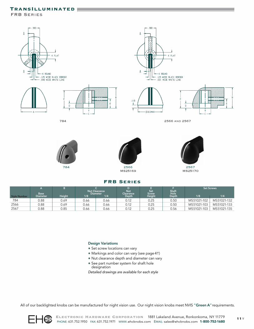
TransIlluminatedFRB Series
FRB Series
2566MS25169
2567MS25170
784
A B C D E F Set ScrewsNut Clearance Nut Set Shaft
Base Diameter Clearance Screw HoleDiameter Height 1/8 1/4 Depth Height Depth 1/8 1/4
0.88 0.69 0.66 0.66 0.12 0.25 0.50 MS51021-102 MS51021-1320.88 0.69 0.66 0.66 0.12 0.25 0.50 MS51021-103 MS51021-1330.88 0.85 0.66 0.66 0.12 0.25 0.56 MS51021-103 MS51021-135
Style Number
78425662567
Design Variations• Set screw locations can vary• Markings and color can vary (see page4T)• Nut clearance depth and diameter can vary• See part number system for shaft hole
designationDetailed drawings are available for each style
Electronic Hardware Corporation 1881 Lakeland Avenue, Ronkonkoma, NY 11779PHONE: 631.752.1950 FAX: 631.752.1971 WWW.ehcknobs.com EMAIL: [email protected] 1-800-752-1680
All of our backlighted knobs can be manufactured for night vision use. Our night vision knobs meet NVIS “Green A”requirements.
2566 and 2567784
12t
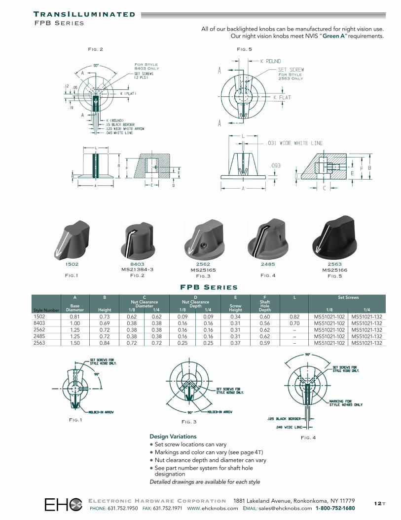
FPB SeriesA B C D E F L Set Screws
Nut Clearance Nut Clearance ShaftBase Diameter Depth Screw Hole
Diameter Height 1/8 1/4 1/8 1/4 Height Depth 1/8 1/4
0.81 0.73 0.62 0.62 0.09 0.09 0.34 0.60 0.82 MS51021-102 MS51021-1321.00 0.69 0.38 0.38 0.16 0.16 0.31 0.56 0.70 MS51021-102 MS51021-1321.25 0.72 0.38 0.38 0.16 0.16 0.31 0.62 – MS51021-102 MS51021-1321.25 0.72 0.38 0.38 0.16 0.16 0.31 0.62 – MS51021-102 MS51021-1321.50 0.84 0.72 0.72 0.25 0.25 0.37 0.59 – MS51021-102 MS51021-132
Style Number
15028403256224852563
2562MS25165Fig.3
2563MS25166Fig.5
2485
Fig. 4
1502
Fig.1
8403MS21384-3Fig.2
Design Variations• Set screw locations can vary• Markings and color can vary (see page4T)• Nut clearance depth and diameter can vary• See part number system for shaft hole
designationDetailed drawings are available for each style
For Style2563 Only
For Style8403 Only
Fig.1 Fig. 3
Fig. 4
Fig. 2 Fig. 5
TransIlluminatedFPB Series
Electronic Hardware Corporation 1881 Lakeland Avenue, Ronkonkoma, NY 11779PHONE: 631.752.1950 FAX: 631.752.1971 WWW.ehcknobs.com EMAIL: [email protected] 1-800-752-1680
All of our backlighted knobs can be manufactured for night vision use.Our night vision knobs meet NVIS “Green A”requirements.
13t
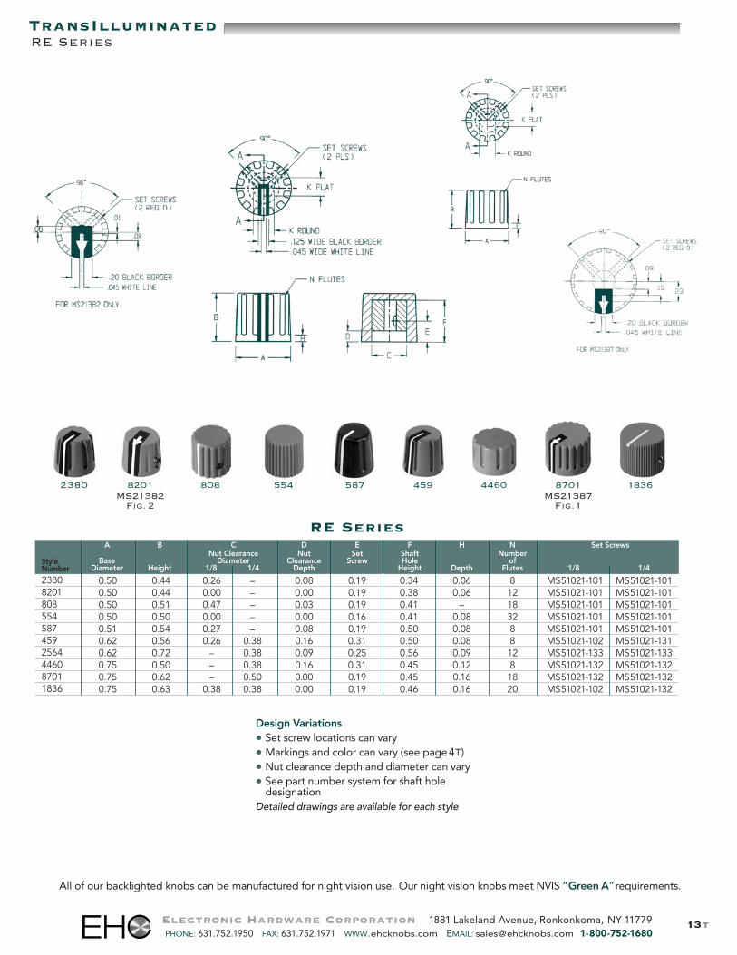
TransIlluminatedRE Series
2380 8201MS21382Fig. 2
587 459 8701MS21387Fig.1
554 18364460
RE SeriesA B C D E F H N Set Screws
Nut Clearance Nut Set Shaft NumberBase Diameter Clearance Screw Hole of
Diameter Height 1/8 1/4 Depth Height Depth Flutes 1/8 1/4
0.50 0.44 0.26 – 0.08 0.19 0.34 0.06 8 MS51021-101 MS51021-1010.50 0.44 0.00 – 0.00 0.19 0.38 0.06 12 MS51021-101 MS51021-1010.50 0.51 0.47 – 0.03 0.19 0.41 – 18 MS51021-101 MS51021-1010.50 0.50 0.00 – 0.00 0.16 0.41 0.08 32 MS51021-101 MS51021-1010.51 0.54 0.27 – 0.08 0.19 0.50 0.08 8 MS51021-101 MS51021-1010.62 0.56 0.26 0.38 0.16 0.31 0.50 0.08 8 MS51021-102 MS51021-1310.62 0.72 – 0.38 0.09 0.25 0.56 0.09 12 MS51021-133 MS51021-1330.75 0.50 – 0.38 0.16 0.31 0.45 0.12 8 MS51021-132 MS51021-1320.75 0.62 – 0.50 0.00 0.19 0.45 0.16 18 MS51021-132 MS51021-1320.75 0.63 0.38 0.38 0.00 0.19 0.46 0.16 20 MS51021-102 MS51021-132
StyleNumber
238082018085545874592564446087011836
Electronic Hardware Corporation 1881 Lakeland Avenue, Ronkonkoma, NY 11779PHONE: 631.752.1950 FAX: 631.752.1971 WWW.ehcknobs.com EMAIL: [email protected] 1-800-752-1680
Design Variations• Set screw locations can vary• Markings and color can vary (see page4T)• Nut clearance depth and diameter can vary• See part number system for shaft hole
designationDetailed drawings are available for each style
All of our backlighted knobs can be manufactured for night vision use. Our night vision knobs meet NVIS “Green A”requirements.
808
14t
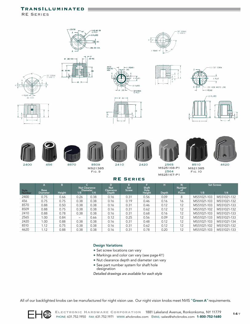
Design Variations• Set screw locations can vary• Markings and color can vary (see page4T)• Nut clearance depth and diameter can vary• See part number system for shaft hole
designationDetailed drawings are available for each style
TransIlluminatedRE Series
Electronic Hardware Corporation 1881 Lakeland Avenue, Ronkonkoma, NY 11779PHONE: 631.752.1950 FAX: 631.752.1971 WWW.ehcknobs.com EMAIL: [email protected] 1-800-752-1680
All of our backlighted knobs can be manufactured for night vision use. Our night vision knobs meet NVIS “Green A”requirements.
8509MS21385Fig. 9
24202410 8510MS21385Fig.102564
MS25167-P1
2400 456 2565MS25168-P1
RE SeriesA B C D E F H N Set Screws
Nut Clearance Nut Set Shaft NumberBase Diameter Clearance Screw Hole of
Diameter Height 1/8 1/4 Depth Height Depth Flutes 1/8 1/4
0.75 0.66 0.26 0.38 0.16 0.31 0.56 0.09 8 MS51021-103 MS51021-1320.75 0.75 0.38 0.38 0.16 0.19 0.46 0.16 16 MS51021-103 MS51021-1320.88 0.50 0.38 0.38 0.16 0.31 0.46 0.12 12 MS51021-103 MS51021-1330.88 0.75 0.38 0.38 0.16 0.31 0.62 0.12 12 MS51021-102 MS51021-1320.88 0.78 0.38 0.38 0.16 0.31 0.68 0.16 12 MS51021-103 MS51021-1331.00 0.84 – 0.66 0.12 0.25 0.56 0.09 12 MS51021-133 MS51021-1331.00 0.88 0.38 0.38 0.16 0.31 0.48 0.12 12 MS51021-103 MS51021-1341.12 0.75 0.38 0.38 0.16 0.31 0.62 0.12 12 MS51021-102 MS51021-1321.12 0.88 0.38 0.38 0.16 0.31 0.78 0.20 12 MS51021-103 MS51021-133
StyleNumber
24004568570850924102565242085104620
46208570
215t
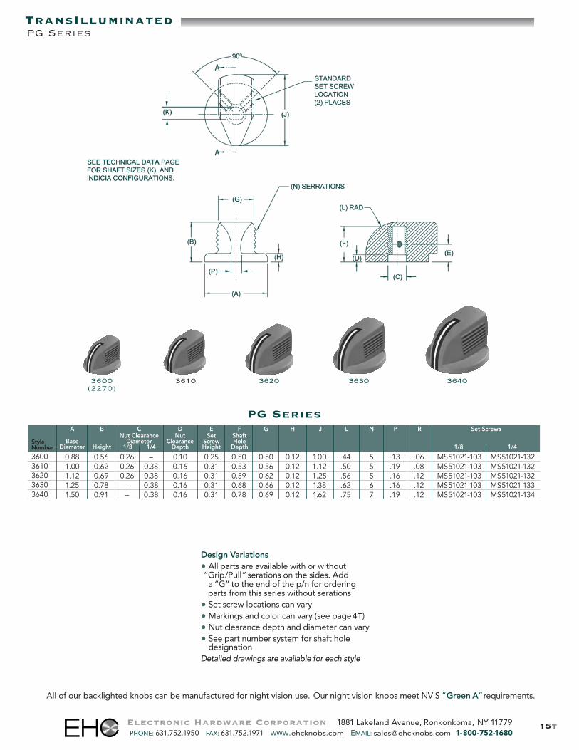
PG Series
3600(2270)
3610 3620 3630 3640
A B C D E F G H J L N P R Set ScrewsNut Clearance Nut Set Shaft
Base Diameter Clearance Screw HoleDiameter Height 1/8 1/4 Depth Height Depth 1/8 1/4
0.88 0.56 0.26 – 0.10 0.25 0.50 0.50 0.12 1.00 .44 5 .13 .06 MS51021-103 MS51021-1321.00 0.62 0.26 0.38 0.16 0.31 0.53 0.56 0.12 1.12 .50 5 .19 .08 MS51021-103 MS51021-1321.12 0.69 0.26 0.38 0.16 0.31 0.59 0.62 0.12 1.25 .56 5 .16 .12 MS51021-103 MS51021-1321.25 0.78 – 0.38 0.16 0.31 0.68 0.66 0.12 1.38 .62 6 .16 .12 MS51021-103 MS51021-1331.50 0.91 – 0.38 0.16 0.31 0.78 0.69 0.12 1.62 .75 7 .19 .12 MS51021-103 MS51021-134
StyleNumber
36003610362036303640
Design Variations• All parts are available with or without“Grip/Pull” serations on the sides. Adda “G” to the end of the p/n for orderingparts from this series without serations
• Set screw locations can vary• Markings and color can vary (see page4T)• Nut clearance depth and diameter can vary• See part number system for shaft hole
designationDetailed drawings are available for each style
Electronic Hardware Corporation 1881 Lakeland Avenue, Ronkonkoma, NY 11779PHONE: 631.752.1950 FAX: 631.752.1971 WWW.ehcknobs.com EMAIL: [email protected] 1-800-752-1680
TransIlluminatedPG Series
All of our backlighted knobs can be manufactured for night vision use. Our night vision knobs meet NVIS “Green A”requirements.
16t
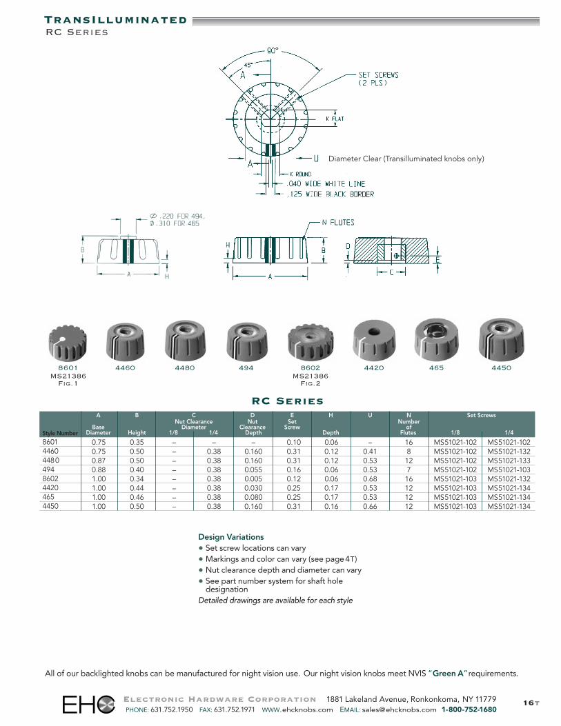
RC Series
8601MS21386Fig.1
4460 494 44504480 44208602MS21386Fig.2
465
A B C D E H U N Set ScrewsNut Clearance Nut Set Number
Base Diameter Clearance Screw ofDiameter Height 1/8 1/4 Depth Depth Flutes 1/8 1/4
0.75 0.35 – – – 0.10 0.06 – 16 MS51021-102 MS51021-1020.75 0.50 – 0.38 0.160 0.31 0.12 0.41 8 MS51021-102 MS51021-1320.87 0.50 – 0.38 0.160 0.31 0.12 0.53 12 MS51021-102 MS51021-1330.88 0.40 – 0.38 0.055 0.16 0.06 0.53 7 MS51021-102 MS51021-1031.00 0.34 – 0.38 0.005 0.12 0.06 0.68 16 MS51021-103 MS51021-1321.00 0.44 – 0.38 0.030 0.25 0.17 0.53 12 MS51021-103 MS51021-1341.00 0.46 – 0.38 0.080 0.25 0.17 0.53 12 MS51021-103 MS51021-1341.00 0.50 – 0.38 0.160 0.31 0.16 0.66 12 MS51021-103 MS51021-134
Style Number
860144604480494860244204654450
Design Variations• Set screw locations can vary• Markings and color can vary (see page4T)• Nut clearance depth and diameter can vary• See part number system for shaft hole
designationDetailed drawings are available for each style
Diameter Clear (Transilluminated knobs only)
TransIlluminated
Electronic Hardware Corporation 1881 Lakeland Avenue, Ronkonkoma, NY 11779PHONE: 631.752.1950 FAX: 631.752.1971 WWW.ehcknobs.com EMAIL: [email protected] 1-800-752-1680
RC Series
All of our backlighted knobs can be manufactured for night vision use. Our night vision knobs meet NVIS “Green A”requirements.
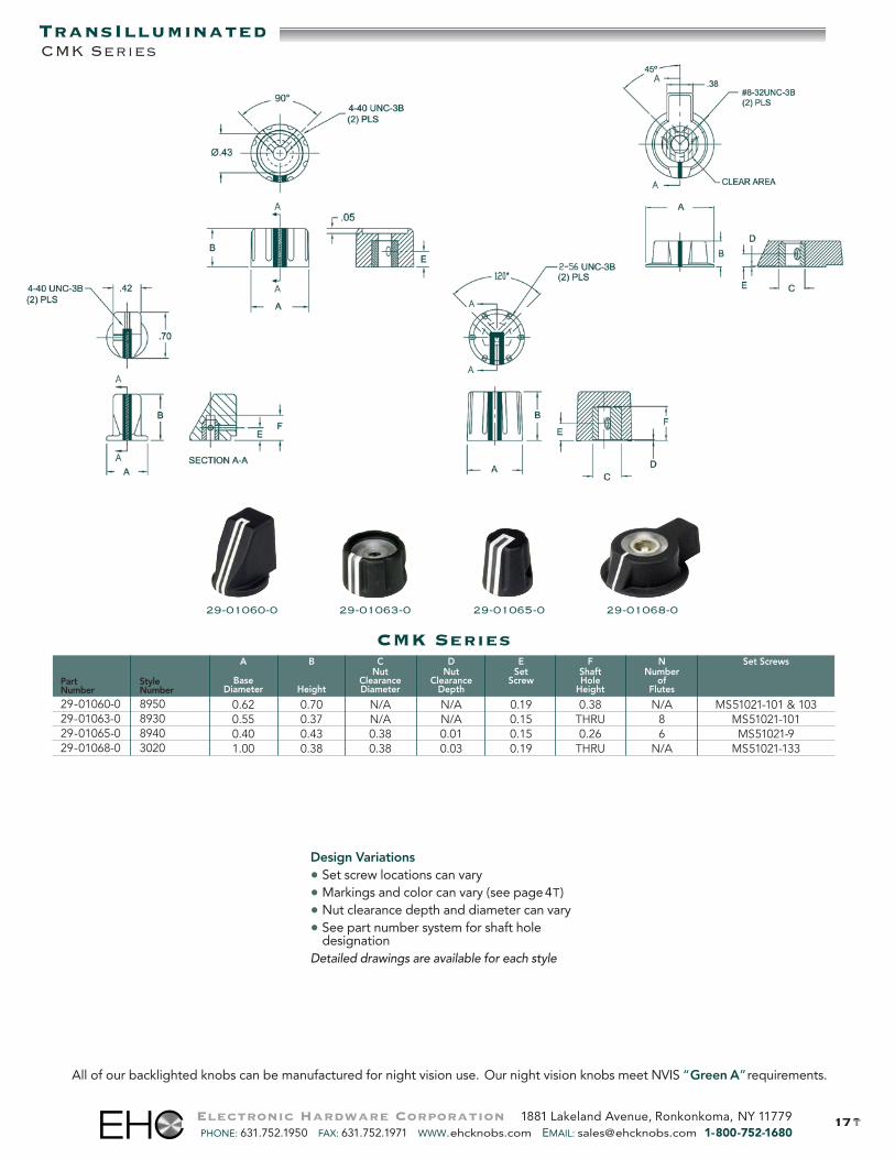
29-01065-029-01060-0 29-01068-029-01063-0
CMK SeriesA B C D E F N Set Screws
Nut Nut Set Shaft NumberBase Clearance Clearance Screw Hole of
Diameter Height Diameter Depth Height Flutes
0.62 0.70 N/A N/A 0.19 0.38 N/A MS51021-101 & 1030.55 0.37 N/A N/A 0.15 THRU 8 MS51021-1010.40 0.43 0.38 0.01 0.15 0.26 6 MS51021-91.00 0.38 0.38 0.03 0.19 THRU N/A MS51021-133
Part StyleNumber Number
29-01060-0 895029-01063-0 893029-01065-0 894029-01068-0 3020
217t
Design Variations• Set screw locations can vary• Markings and color can vary (see page4T)• Nut clearance depth and diameter can vary• See part number system for shaft hole
designationDetailed drawings are available for each style
Electronic Hardware Corporation 1881 Lakeland Avenue, Ronkonkoma, NY 11779PHONE: 631.752.1950 FAX: 631.752.1971 WWW.ehcknobs.com EMAIL: [email protected] 1-800-752-1680
TransIlluminatedCMK Series
All of our backlighted knobs can be manufactured for night vision use. Our night vision knobs meet NVIS “Green A”requirements.
18t
TransIlluminated
Electronic Hardware Corporation 1881 Lakeland Avenue, Ronkonkoma, NY 11779PHONE: 631.752.1950 FAX: 631.752.1971 WWW.ehcknobs.com EMAIL: [email protected] 1-800-752-1680
All of our backlighted knobs can be manufactured for night vision use. Our night vision knobs meet NVIS “Green A”requirements.
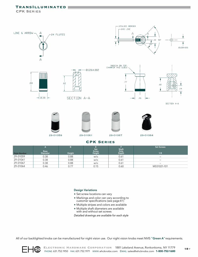
CPK Series
Design Variations• Set screw locations can vary• Markings and color can vary according to• customer specifications (see page4T)• Multiple stripes and colors are available• Multiple shaft diameters are available• with and without set screwsDetailed drawings are available for each style
CPK Series
29-01059 29-01061 29-01067 29-01064
A B E F Set ScrewsSet Shaft
Base Screw HoleDiameter Height Height Depth 1/8
0.38 0.88 w/o 0.61 –0.38 0.88 w/o 0.61 –0.38 0.88 w/o 0.61 –0.46 0.77 0.15 0.60 MS51021-101
Style Number
29-0105929-0106129-0106729-01064
219tElectronic Hardware Corporation 1881 Lakeland Avenue, Ronkonkoma, NY 11779PHONE: 631.752.1950 FAX: 631.752.1971 WWW.ehcknobs.com EMAIL: [email protected] 1-800-752-1680
TransIlluminated
All of our backlighted knobs can be manufactured for night vision use. Our night vision knobs meet NVIS “Green A”requirements.
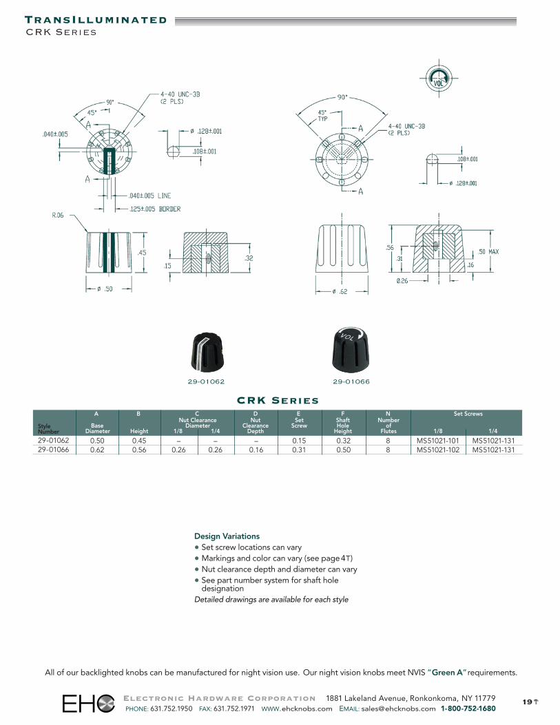
CRK Series
Design Variations• Set screw locations can vary• Markings and color can vary (see page4T)• Nut clearance depth and diameter can vary• See part number system for shaft hole
designationDetailed drawings are available for each style
29-0106629-01062
CRK SeriesA B C D E F N Set Screws
Nut Clearance Nut Set Shaft NumberBase Diameter Clearance Screw Hole of
Diameter Height 1/8 1/4 Depth Height Flutes 1/8 1/4
0.50 0.45 – – – 0.15 0.32 8 MS51021-101 MS51021-1310.62 0.56 0.26 0.26 0.16 0.31 0.50 8 MS51021-102 MS51021-131
StyleNumber
29-0106229-01066
20t
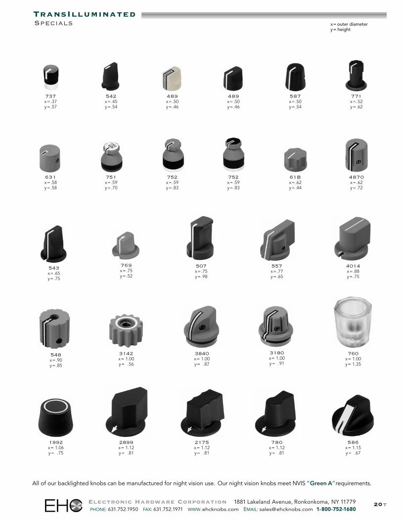
TransIlluminatedSpecials
Electronic Hardware Corporation 1881 Lakeland Avenue, Ronkonkoma, NY 11779PHONE: 631.752.1950 FAX: 631.752.1971 WWW.ehcknobs.com EMAIL: [email protected] 1-800-752-1680
All of our backlighted knobs can be manufactured for night vision use. Our night vision knobs meet NVIS “Green A”requirements.
771x=.52y=.62
x= outer diametery= height
1992x= 1.06y=1.75
3142x= 1.00y=1.56
2899x= 1.12y=1.81
557x=.77y=.65
4014x=.88y=.75
3840x= 1.00y=1.87
3180x= 1.00y=1.91
548x=.90y=.85
507x=.75y=.98
760x= 1.00y= 1.35
737x=.37y=.57
631x=.58y=.58
542x=.45y=.54
751x=.59y=.70
489x=.50y=.46
752x=.59y=.83
752x=.59y=.83
489x=.50y=.46
61Bx=.62y=.44
587x=.50y=.54
4870x=.62y=.72
543x=.65y=.75
586x= 1.15y=1.67
2175x= 1.12y=1.81
780x= 1.12y=1.81
769x=.75y=.52

All of our backlighted knobs can be manufactured for night vision use. Our night vision knobs meet NVIS “Green A”requirements.
21t
Special Knobsx= outer diametery= height
228x=.35y=.51
688x=.44y=.78
489x=.50y=.46
432x=.52y=.72
458x=.69y= .40
3214x=.70y=.50
352x=.83y=.64
2066x=1.07y= .83
2685x=.90y=.52
3081x=.51y=.77
2271538A125x=.82y=.51
705x=1.33y=1.26
3680x=1.52y= .86
1047x= .90y=1.03
3283x=1.26y= .86
696 M32x=1.00y= .80
706 D21x=.90y=.70
850x=1.33y=1.26
494x=.88y=.39
2580x=.87y=.36
1599 D42x=.51y=.77
707 M43x=1.25y= .72
708 M32x=1.02y= .88
68-00013-0x=1.25y= .72
1803 D31x=1.26y= .86
Electronic Hardware Corporation 1881 Lakeland Avenue, Ronkonkoma, NY 11779PHONE: 631.752.1950 FAX: 631.752.1971 WWW.ehcknobs.com EMAIL: [email protected] 1-800-752-1680

22tElectronic Hardware Corporation 1881 Lakeland Avenue, Ronkonkoma, NY 11779PHONE: 631.752.1950 FAX: 631.752.1971 WWW.ehcknobs.com EMAIL: [email protected] 1-800-752-1680
All of our backlighted knobs can be manufactured for night vision use. Our night vision knobs meet NVIS “Green A”requirements.
TransIlluminatedSpecials x= outer diameter
y= height
FNA 3216/3217x=.94y=.50
FNA 3292x=1.68y= .60
696x=1.39y= .55
FNA 2040x=1.68y= .60
FNA 2592x=1.68y= .31
FNA 2055/2059x=.88y=.81
2408 D51x=2.00y= .70
65D 13295-2x=.75y=.75
FNA 17151 3014x=1.78y= .80
FNA 3797-1x=1.15y= .25
788x=.43y=.79
808x=.50y=.50
FNA 39193x=1.26y= .86
785x=.94y=.50
1735x=1.15y=1.25
4110x=1.50y=1.00
830x=1.22y=1.10.50
571x=1.06y= .69
840x=.84y=.91
856x=1.50y= .70
854x=.88y=.70
527x=.81y=.81y=.78
730x=.62y=.47
731x=.63y=.50
733x=.40y=.50
23tElectronic Hardware Corporation 1881 Lakeland Avenue, Ronkonkoma, NY 11779PHONE: 631.752.1950 FAX: 631.752.1971 WWW.ehcknobs.com EMAIL: [email protected] 1-800-752-1680
Resins–much of the growth of the injection molding industry is due to the continuing ability of resin suppliersto offer new and improved engineering materials. Today resins can meet specifications for mechanical, thermal,electrical and impact demands increasingly competitive in performance to metal at reduced processing costs.
EHC’s participates in an ongoing evaluation process of new resins. Moldability, ease of processing and decorationare some of the analysis conducted. This process provides for a continuing effort to improve current productionneeds and prepare for future program demands.
• Good Mechanical Strength and Illumination are of primary concern when choosing our materials.strength is needed numerous reinforcements are used including glass fibers, mineral fillers, glass microspheres,all products that improve impact resistance.
• Electrical Resistance or Insulation make the use of EHC plastic products especially suited in electro-mechanical environments.
The plastic materials used in EHC parts have been carefully selected to meet the functional and aestheticrequirements of each product.
Thermoplastic – Materials with technical characteristics such as polycarbonate unless otherwise requestedby customers.
InspectionStandardParts are considered commercially non-acceptable if an imper-fection is visible when viewed at arm‘s length distance undernormal lighting conditions. Parts will be viewed for a periodnot to exceed 3-5 seconds in daylight (or fluorescent light ofapproximately 70 foot candles) with the unaided eye at normalviewing distance of 24 inches, in the normal viewing plane.
SpecialJewelry-type inspection will be reflected in a higher unit-cost.Customer to provide EHC with written notice in advance ofplacement of order.
Chemical ResistanceContact manufacturer for resistance factors prior to usagewith chemicals.
Surface Finish1. Gloss: Parts produced from a highly polished mold, or2. Satin: Parts produced from a textured mold to remove
glossiness,or
3. Textured: Parts produced from a pattern etched mold, or4. Matte-finish: Parts produced from a secondary operation
that provides a non-reflective plastic surface.Appearance
Parts to be free of shrinkage in excess of .009" IN/IN on topsurface and sides of molded knob, mold flow marks or ”cold“spots, molding flash, chips or cracks, excessive gate marksand colors (for knob and skirt assemblies) to be consistentin shade and density for each order lot or release.
MarkingsAdhesion:
Markings cannot be removed from plastic surface by anadhesive material comparable to scotch tape.
Inspection: See opening paragraph.Appearance:
All characters, lettering, border, and backgrounds mustbe complete and all lettering must be clear, visible, andlegible. Colors to be consistent in shade and density foreach order lot or release.
Set ScrewsHexagon Socket
1. Material: high grade alloy steel2. Finish: Corrosion resistant/coating with clear
or black finish3. Hardness: Case hardened4. Finish: Clear corrosion resistant coating5. Point Style: Cup point
Location (nominal) of Screw(s) (if applicable)Two (2) set screws at 45˚ from 12 o’clockor 90º and 180º from indicator.
ThreadClass 3A
Screw Size and LengthDetermined by manufacturer.
Inserts1. Material: Aluminum or half-hard brass alloy.2. Finish Options: Nickel plate on brass or2. Finish Options: Anodized on aluminum.
ThreadThread Fit: 2B gauge
PackagingAll products are packaged to insure that quality is not jeopardizedduring transit. Relative to the complexity of the part, product is:
A. Individual bags, orB. Egg crate box w/ foam pads on top and bottom
Materials
MaterialSpecifications
Technical Data

24tElectronic Hardware Corporation 1881 Lakeland Avenue, Ronkonkoma, NY 11779PHONE: 631.752.1950 FAX: 631.752.1971 WWW.ehcknobs.com EMAIL: [email protected] 1-800-752-1680
Sales Terms & Agreements
Our terms of sale are 1/10 net 30 FOB Farmingdale, NY.Terms on tooling are 50% with order balance upon sample approval.
Terms:
All returns must be approved by EHC and be assigned an EHC RMA number.Returns:
We reserve the right to over or under ship10% on orders for non-standard parts.OTY Variance:
Usually UPS or FedEx prepaid and added, unless otherwise specified.Shipments:
Immediate and just-in-time delivery is available on most standard items.Delivery:
Storage of customer owned artworkpreparation, raw materials and supplies,and tooling.Customer shall notify EHC of discontin-uance of product for which customer haspurchased items so that arrangementscan be made to return or discard them.Our standard practice assumes that itemsnot used by the customer for a period oftwo years will be considered of no valueand customer will be notified of ourdecision. Failure of customer to respond toinquiry leaves disbursement of itemsat the discretion of EHC (at no chargeor obligation).
Specifications for non-standard productsmust be approved by EHC. Specifications whichcall for closer tolerances, enhanced physicalproperties, or more stringent visual require-ments than those previously listed must havespecific approval of EHC’s sales and manufac-turing organizations.
Note: Shrinkage, toolmakers variations fromcavity to cavity, life-cycle of tooling, materialsfrom multiple vendors, humidity, etc. all havean effect on the normal dimensions of plasticparts. A premium charge will be added tothe unit-cost for those customers requiringexact tolerances and appearance. Contactmanufacturer for additional charges.
Product Dimensions: XX = +– .02"and XXX = +– .010"unless otherwise specified.
Product Concentricity: .020" TIR
Shafthole DiametersRound Shaft Hole: +– .002"
Round Shaft Hole with Flat:: +– .0035"
Knurled Shaft Hole:
Solid Shaft: +– .002"
Split Shaft: +– .0035"
Torque SpecificationsTorque is defined as the number of pounds required to stripmolded-in inserts and stud heads from molded plastic part,flatten metal spring clip, strip serration of knurled plastic shafthole or strip head of set screw.
Spring Clip Shaft Hole StrippingTorque
Spring Diameter Inch Lbs.
.125 10
.187 17
6 mm 25
.250 25
Knurled Type Shaft Hole: All types 15 inch lbs.
Set Screws HeadStripping
Screw Threads TorqueSize Per In. Inch Lbs.
#3 48 3-1/2
#4 40 4-3/4
#6 32 8-3/4
#8 32 18
#10 32 32
Shaft Hole SpecificationsShaft hole fit per customer specifications can be provided foran additional charge. Sample shaft and tension requirementsmust be forwarded to manufacturer.
Inserts with Threaded I.D.(Standard Series and Selected Combinations – UnifiedScrew Threads)
Thread Fit: 2B Gauge
Thread Type#6-32 UNC 2B
#8-32 UNC 2B
#10-32 UNF 2B
1/4-20 UNC 2B
5/16-18 UNC 2B
3/8-16 UNC 2B
7/16-14 UNC 2B
1/2-13 UNC 2B
Mechanical Tolerances
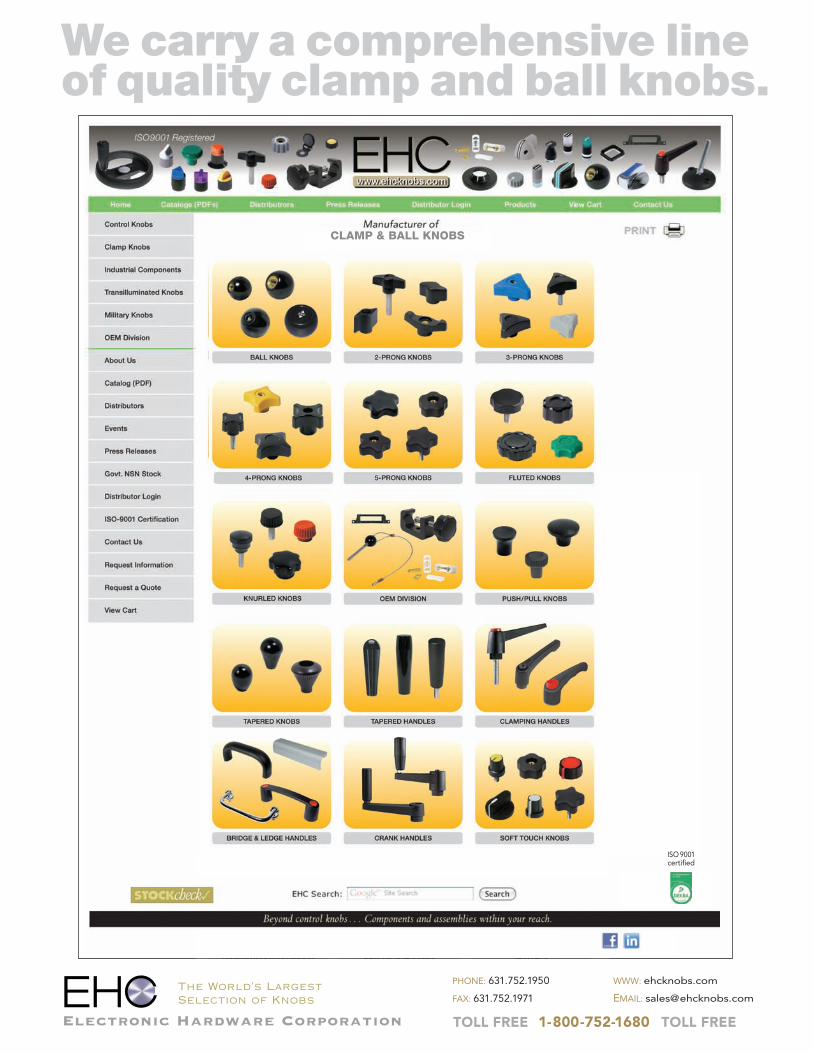
We carry a comprehensive lineof quality clamp and ball knobs.
The World’s LargestSelection of Knobs
Electronic Hardware Corporation
PHONE: 631.752.1950
FAX: 631.752.1971
WWW: ehcknobs.com
EMAIL: [email protected]
TOLL FREE 1-800-752-1680 TOLL FREE
CLAMP & BALL KNOBS
ISO 9001certified
Recommended