TRACK SPECIFICATION
LOW PROFILE CONCRETE SLEEPERS
MTSP 000003-01 Version: 3 Effective from: 27th April 2015
L2-TRK-SPE-003
Approving Manager: Chief Engineer Approval Date: 27/04/2015 Next Review Date: 27/04/2018
PRINTOUT MAY NOT BE UP-TO-DATE; REFER TO METRO INTRANET FOR THE LATEST VERSION Page 1 of 17
Approval
Amendment Record
Approval Date Version Description
19/04/2013 1 Initial issue under MTM.
19/02/2014 2 Details for Train Stop sleepers added and figures updated
27/04/2015 3 Amended the design track speed vs design axle load table to
reflect current network operations.
TRACK SPECIFICATION
LOW PROFILE CONCRETE SLEEPERS
MTSP 000003-01 Version: 3 Effective from: 27th April 2015
L2-TRK-SPE-003
Approving Manager: Chief Engineer Approval Date: 27/04/2015 Next Review Date: 27/04/2018
PRINTOUT MAY NOT BE UP-TO-DATE; REFER TO METRO INTRANET FOR THE LATEST VERSION Page 2 of 17
Table of Contents
1. Purpose ..................................................................................................................4
2. Scope ......................................................................................................................4
3. References .............................................................................................................4
4. Abbreviations .........................................................................................................5
5. Definitions ..............................................................................................................5
6. Responsibilities .....................................................................................................6
7. Safety and Environmental .....................................................................................6
8. Design Requirements ............................................................................................6
8.1 General ...............................................................................................................................6
8.2 Components .......................................................................................................................6
8.3 Design Criteria ....................................................................................................................7
8.4 Allowance for Retrofit (Train Stop Sleepers) ......................................................................9
9. Design Management ..............................................................................................9
9.1 General ...............................................................................................................................9
9.1.1 Operating Considerations ............................................................................. 9
9.2 Sleeper Design ................................................................................................................ 10
9.2.1 Design Verification ...................................................................................... 10
9.2.2 Production Validation .................................................................................. 10
9.3 Service Life ...................................................................................................................... 10
9.4 Drawings .......................................................................................................................... 10
9.4.1 Drawings Layout Requirements – General ................................................. 11
9.4.2 LPCS Drawing Details & Requirements ..................................................... 11
9.5 Design and Production .................................................................................................... 11
9.6 Sleeper Marking .............................................................................................................. 12
10. Performance Requirements ................................................................................ 12
10.1 Handling and Maintenance Performance ........................................................................ 12
11. Performance Measures and Reporting .............................................................. 12
11.1 Quality Assurance ........................................................................................................... 12
11.1.1 ISO 9001 Quality Management System ..................................................... 12
11.1.2 Retention of Documents ............................................................................. 13
11.1.3 Certificate of Conformity ............................................................................. 13
TRACK SPECIFICATION
LOW PROFILE CONCRETE SLEEPERS
MTSP 000003-01 Version: 3 Effective from: 27th April 2015
L2-TRK-SPE-003
Approving Manager: Chief Engineer Approval Date: 27/04/2015 Next Review Date: 27/04/2018
PRINTOUT MAY NOT BE UP-TO-DATE; REFER TO METRO INTRANET FOR THE LATEST VERSION Page 3 of 17
11.1.4 Audit of Supplier .......................................................................................... 13
11.1.5 Provision of Records ................................................................................... 13
11.2 Supply and Delivery Requirements ................................................................................. 14
12. Type Approval ...................................................................................................... 14
13. Appendices .......................................................................................................... 14
List of Tables
Table 1 - Design Criteria ................................................................................................................. 7
Table 2 - Track Class and Maximum Line Speed ............................................................................ 9
List of Figures
Figure 1 - Basic Dimensions of Track Set-up ................................................................................ 15
Figure 2 - Figure identifies layout of rail seats and sleeper dimensions ......................................... 15
Figure 3 - Half Low Profile Concrete Sleeper (mirrored on other side), identifies rail seating inclination (1 in 20). Sleeper height is 150mm at C-C. ................................................................... 15
Figure 4 - Layout for Train Stop fixing bolt configuration ............................................................... 16
Figure 5 - Half Train Stop Sleeper (mirrored on other side), identifies rail seating inclination (1 in 20). Sleeper height is 210mm at D-D. ........................................................................................... 16
TRACK SPECIFICATION
LOW PROFILE CONCRETE SLEEPERS
MTSP 000003-01 Version: 3 Effective from: 27th April 2015
L2-TRK-SPE-003
Approving Manager: Chief Engineer Approval Date: 27/04/2015 Next Review Date: 27/04/2018
PRINTOUT MAY NOT BE UP-TO-DATE; REFER TO METRO INTRANET FOR THE LATEST VERSION Page 4 of 17
1. Purpose
This specification sets out the material, design, manufacture, supply and testing requirements for Low Profile Concrete Sleepers used for the MTM railway.
2. Scope
This specification details the requirements for the design and supply of LPCS complete with resilient type fastening assemblies which will be used on MTM railway network.
Concrete sleepers for Train Stop applications are included in this specification. Concrete sleepers for special applications, including multi-gauge tracks and turnout bearers, are not covered by this specification.
System performance requires the concrete sleeper assembly to function as part of the track structure. The sleeper must be able to transfer all the relevant track forces generated by train operations and the forces of rail thermal expansion and contraction to the ballast.
3. References
AS 1085.1 (2002/Amdt 1 - 2005) – Steel Rails
AS 1085.14 (2012) – Prestressed Concrete Sleepers
AS 1085.19 (2003) – Resilient Fastening Assemblies
AS 1379 (2007) – Specification and supply of concrete
AS 3600 (2009) – Concrete Structures
ISO 9001 (2008) – Quality Management
MTST 000002-01 – Track Design and Construction Standard
MTSP 030100-01 – Track Geometry Maintenance Tolerances
MTSP 000003-02 – Supply of Resilient Rail Fastening Assemblies
L1-NAM-PRO-002 – MTM Design and Technical Review Procedure
L1-CHE-PRO-004 – Type Approval Procedure
STD_G0075 – Layout of Train Stop and Signal with Insulated Joints
STD_G0077 – Plate and Pad for top fixing of EP train stop WBS style JAH to concrete sleepers PTC2
STD_G0078 – EP Train Stop W/B&S style JAH method of fixing to top of concrete sleepers PTC2
TRACK SPECIFICATION
LOW PROFILE CONCRETE SLEEPERS
MTSP 000003-01 Version: 3 Effective from: 27th April 2015
L2-TRK-SPE-003
Approving Manager: Chief Engineer Approval Date: 27/04/2015 Next Review Date: 27/04/2018
PRINTOUT MAY NOT BE UP-TO-DATE; REFER TO METRO INTRANET FOR THE LATEST VERSION Page 5 of 17
4. Abbreviations
LPCS – Low Profile Concrete Sleeper
MTM – Metro Trains Melbourne Pty Ltd
NAM – Network Asset Management
PTC – Public Transport Corporation
5. Definitions
Additives – A substance added to another in relatively small amounts to impart or improve desirable properties or suppress undesirable properties.
Bearer – A transverse concrete unit supporting rails
Cast in Shoulder – A component that prevents lateral movement of the rail foot and provides anchorage for the resilient fastening system
Fastening – The component, or group of components of a track system, that fixes the rail to the sleeper
Insulator – A part of the fastening that fits between the resilient clip, shoulder and the rail foot to provide electrical isolation
Monoblock Concrete Sleeper – Prestressed concrete sleeper cast in a single piece
Prestressing Tendon – A strand or wire within a sleeper, which under tension compresses the concrete
Rail Pad – The component that is located between the foot of the rail and the sleeper. Pads may include multiple layers of material
Rail Seat – The area on the top of the sleeper on which the rail sits extending between the field and gauge shoulders.
Resilient Clip – A flexible steel restraint that clamps the rail in position
Resilient Fastenings – Elastic steel clips attached to sleepers and designed to engage rail flanges. These clips fasten rails to the sleepers providing lateral support. Resilient fastenings also generate toe load at the rail flange providing resistance to longitudinal movement, rail roll and rail lateral shift.
Shall – Is to be interpreted as a requirement that is mandatory to achieve conformance to this specification.
Technical MTM Representative – The Infrastructure Delivery Manager or his delegated representative.
Track Gauge – The distance between the running face at the head of the rails measured 16mm below the top of rail head when assembled.
Train Stop – A mechanism that will automatically result in the application of the train brakes if the train passes a signal at danger.
TRACK SPECIFICATION
LOW PROFILE CONCRETE SLEEPERS
MTSP 000003-01 Version: 3 Effective from: 27th April 2015
L2-TRK-SPE-003
Approving Manager: Chief Engineer Approval Date: 27/04/2015 Next Review Date: 27/04/2018
PRINTOUT MAY NOT BE UP-TO-DATE; REFER TO METRO INTRANET FOR THE LATEST VERSION Page 6 of 17
6. Responsibilities
All suppliers shall be responsible for conformance to this document.
The Technical Representative of MTM shall be responsible for the management of the technical requirements and ensure compliance in accordance with the MTM documented processes relevant to this specification.
7. Safety and Environmental
The design and manufacture of low profile concrete sleepers shall consider the safe application and handling of the sleepers during installation and ensure the product is safe for use with no adverse impacts on the health and safety of workers who may come in contact with the product. As part of the Type Approval evaluation criteria the product will need to demonstrate that it is suitable for use within the environment. The product shall be free of any hazardous materials and the details of all components including any additives used in the manufacture of the sleeper must be approved by MTM.
8. Design Requirements
8.1 General
The design shall be in accordance with AS 1085.14 – Prestressed Concrete Sleepers, unless otherwise noted within this document.
Alternative design techniques and materials may be used where the manufacturer can demonstrate compliance with the requirements of Sections 5 and 6 of AS 1085.14 (2012) and other requirements, to the satisfaction of MTM. In this instance, a Type Approval Application will be required by the MTM Network Asset Manager.
The sleepers shall be designed to operate as specified in Table 1 and Table 2, which provide design information relating to track and rail operations where the prestressed sleepers will be used. Designs shall be verified by a competent independent third party organisation that has prior approval and endorsement by MTM / NAM.
8.2 Components
For all specified requirements to achieve adequate load transfer, which includes details on fastenings, insulation, rail pads, etc. can be found in the MTM document MTSP 000003-02 ‘Track Specification – Supply of Resilient Rail Fastening Assemblies’.
TRACK SPECIFICATION
LOW PROFILE CONCRETE SLEEPERS
MTSP 000003-01 Version: 3 Effective from: 27th April 2015
L2-TRK-SPE-003
Approving Manager: Chief Engineer Approval Date: 27/04/2015 Next Review Date: 27/04/2018
PRINTOUT MAY NOT BE UP-TO-DATE; REFER TO METRO INTRANET FOR THE LATEST VERSION Page 7 of 17
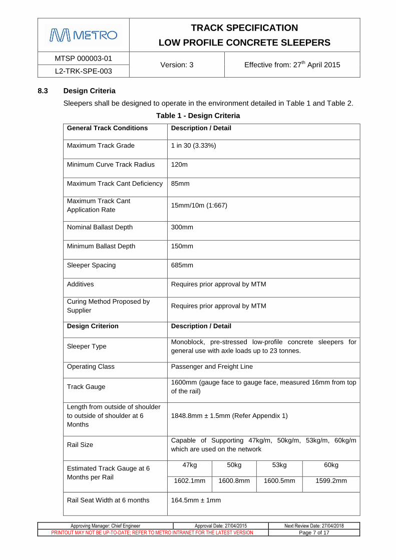
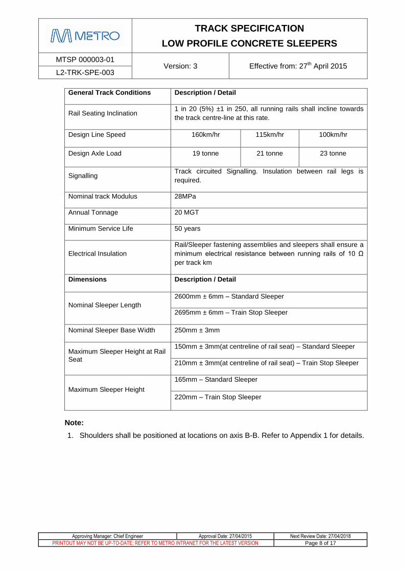
8.3 Design Criteria
Sleepers shall be designed to operate in the environment detailed in Table 1 and Table 2.
Table 1 - Design Criteria
General Track Conditions Description / Detail
Maximum Track Grade 1 in 30 (3.33%)
Minimum Curve Track Radius 120m
Maximum Track Cant Deficiency 85mm
Maximum Track Cant
Application Rate 15mm/10m (1:667)
Nominal Ballast Depth 300mm
Minimum Ballast Depth 150mm
Sleeper Spacing 685mm
Additives Requires prior approval by MTM
Curing Method Proposed by
Supplier Requires prior approval by MTM
Design Criterion Description / Detail
Sleeper Type Monoblock, pre-stressed low-profile concrete sleepers for
general use with axle loads up to 23 tonnes.
Operating Class Passenger and Freight Line
Track Gauge 1600mm (gauge face to gauge face, measured 16mm from top
of the rail)
Length from outside of shoulder
to outside of shoulder at 6
Months
1848.8mm ± 1.5mm (Refer Appendix 1)
Rail Size Capable of Supporting 47kg/m, 50kg/m, 53kg/m, 60kg/m
which are used on the network
Estimated Track Gauge at 6
Months per Rail
47kg 50kg 53kg 60kg
1602.1mm 1600.8mm 1600.5mm 1599.2mm
Rail Seat Width at 6 months 164.5mm ± 1mm
TRACK SPECIFICATION
LOW PROFILE CONCRETE SLEEPERS
MTSP 000003-01 Version: 3 Effective from: 27th April 2015
L2-TRK-SPE-003
Approving Manager: Chief Engineer Approval Date: 27/04/2015 Next Review Date: 27/04/2018
PRINTOUT MAY NOT BE UP-TO-DATE; REFER TO METRO INTRANET FOR THE LATEST VERSION Page 8 of 17
General Track Conditions Description / Detail
Rail Seating Inclination 1 in 20 (5%) ±1 in 250, all running rails shall incline towards
the track centre-line at this rate.
Design Line Speed 160km/hr 115km/hr 100km/hr
Design Axle Load 19 tonne 21 tonne 23 tonne
Signalling Track circuited Signalling. Insulation between rail legs is
required.
Nominal track Modulus 28MPa
Annual Tonnage 20 MGT
Minimum Service Life 50 years
Electrical Insulation
Rail/Sleeper fastening assemblies and sleepers shall ensure a
minimum electrical resistance between running rails of 10 Ω
per track km
Dimensions Description / Detail
Nominal Sleeper Length
2600mm ± 6mm – Standard Sleeper
2695mm ± 6mm – Train Stop Sleeper
Nominal Sleeper Base Width 250mm ± 3mm
Maximum Sleeper Height at Rail Seat
150mm ± 3mm(at centreline of rail seat) – Standard Sleeper
210mm ± 3mm(at centreline of rail seat) – Train Stop Sleeper
Maximum Sleeper Height
165mm – Standard Sleeper
220mm – Train Stop Sleeper
Note:
1. Shoulders shall be positioned at locations on axis B-B. Refer to Appendix 1 for details.
TRACK SPECIFICATION
LOW PROFILE CONCRETE SLEEPERS
MTSP 000003-01 Version: 3 Effective from: 27th April 2015
L2-TRK-SPE-003
Approving Manager: Chief Engineer Approval Date: 27/04/2015 Next Review Date: 27/04/2018
PRINTOUT MAY NOT BE UP-TO-DATE; REFER TO METRO INTRANET FOR THE LATEST VERSION Page 9 of 17
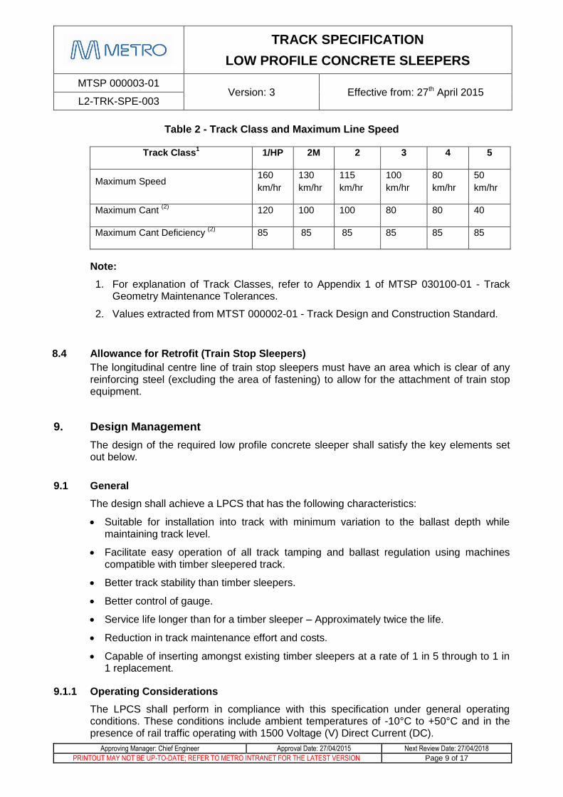
Table 2 - Track Class and Maximum Line Speed
Track Class1 1/HP 2M 2 3 4 5
Maximum Speed 160
km/hr
130
km/hr
115
km/hr
100
km/hr
80
km/hr
50
km/hr
Maximum Cant (2)
120 100 100 80 80 40
Maximum Cant Deficiency (2)
85 85 85 85 85 85
Note:
1. For explanation of Track Classes, refer to Appendix 1 of MTSP 030100-01 - Track Geometry Maintenance Tolerances.
2. Values extracted from MTST 000002-01 - Track Design and Construction Standard.
8.4 Allowance for Retrofit (Train Stop Sleepers)
The longitudinal centre line of train stop sleepers must have an area which is clear of any reinforcing steel (excluding the area of fastening) to allow for the attachment of train stop equipment.
9. Design Management
The design of the required low profile concrete sleeper shall satisfy the key elements set out below.
9.1 General
The design shall achieve a LPCS that has the following characteristics:
Suitable for installation into track with minimum variation to the ballast depth while maintaining track level.
Facilitate easy operation of all track tamping and ballast regulation using machines compatible with timber sleepered track.
Better track stability than timber sleepers.
Better control of gauge.
Service life longer than for a timber sleeper – Approximately twice the life.
Reduction in track maintenance effort and costs.
Capable of inserting amongst existing timber sleepers at a rate of 1 in 5 through to 1 in 1 replacement.
9.1.1 Operating Considerations
The LPCS shall perform in compliance with this specification under general operating conditions. These conditions include ambient temperatures of -10°C to +50°C and in the presence of rail traffic operating with 1500 Voltage (V) Direct Current (DC).
TRACK SPECIFICATION
LOW PROFILE CONCRETE SLEEPERS
MTSP 000003-01 Version: 3 Effective from: 27th April 2015
L2-TRK-SPE-003
Approving Manager: Chief Engineer Approval Date: 27/04/2015 Next Review Date: 27/04/2018
PRINTOUT MAY NOT BE UP-TO-DATE; REFER TO METRO INTRANET FOR THE LATEST VERSION Page 10 of 17
9.2 Sleeper Design
The Supplier shall describe the sleeper design process that is to be applied. The design shall be based on proven structural design principles, incorporating finite analysis techniques and consider fatigue as well as ultimate capacity.
9.2.1 Design Verification
The Supplier shall document the process used for the design and MTM shall approve the design before the manufacture and supply of concrete sleepers.
The Supplier shall document the process for the design process and the independent validation of the design by a third party. The design and validation of the concrete sleeper shall be in accordance with the MTM Engineering Design Procedure attached to this specification: ‘L1-NAM-PRO-002 – MTM Design and Technical Review Procedure’.
The Supplier shall provide a Design Report detailing any non compliance to Australian Standards and any Design Limitations to be considered during installation and train operation as detailed in Table 1 – Design Criteria.
The Design report shall describe the range of operating conditions and practices that would apply to the track where LPCS are used. Where there are restrictions on the use of the sleeper these shall be highlighted in the report i.e. curved radius track, concrete sleepers interspersed with timber or heavy duty PTC concrete sleepers and track grades etc.
9.2.2 Production Validation
The Supplier shall demonstrate that the loadings used in the sleeper design are valid. A batching sample of 10 no. sleepers shall be supplied to MTM for checking against the final Supplier approved drawings to be used for the manufacture of sleepers. MTM shall arrange for independent testing to ensure compliance to MTM standards and operating requirements. The Supplier shall undertake their own validation testing and provide MTM with the test results. This validation by MTM and the Supplier must be completed prior to the commencement of full production of sleepers.
9.3 Service Life
The Supplier shall provide the theoretical service life for the proposed sleeper when used under a range of track conditions. The track geometry parameters for the various track classes and speeds as detailed in Appendix 1 of MTSP 030100-01 – Track Geometry Maintenance Tolerances including potential increase in axle loads, change in rail size, change in ballast support conditions and any change in the impact characteristics of rolling stock shall be considered.
9.4 Drawings
MTM reserves the right, and will give reasonable notice, to request further information not contained or included in delivered drawings to ensure adequate description of supplied LPCS, in accordance with this specification.
The Supplier shall provide a dimensioned (together with tolerances applied to the external and internal dimensions) drawing or drawings of the LPCS. Accordingly, the Supplier shall ensure that all pertinent information listed below has been included on the drawings.
TRACK SPECIFICATION
LOW PROFILE CONCRETE SLEEPERS
MTSP 000003-01 Version: 3 Effective from: 27th April 2015
L2-TRK-SPE-003
Approving Manager: Chief Engineer Approval Date: 27/04/2015 Next Review Date: 27/04/2018
PRINTOUT MAY NOT BE UP-TO-DATE; REFER TO METRO INTRANET FOR THE LATEST VERSION Page 11 of 17
9.4.1 Drawings Layout Requirements – General
All Dimensions and their units in millimetres (mm)
All writing in English
Signatures provided by designer, reviewer and approver and dates
Drawing number and title
Drawing version number and details
Explanatory Notes
Supplier title block / name
9.4.2 LPCS Drawing Details & Requirements
The details shall include but not be limited to:
Type and Grade of Steel
Pre-Tensioning of Steel bars
Number and Size of Steel Reinforcing/Stressing Bars
Strength of Concrete
Details of Aggregates in Concrete (i.e. sand, gravel, etc.)
Type of Cement
Details of Additives used, if any
Branding description
Gauge measurements and details
Rail Seat measurements
Cast in shoulder details
Reinforcement details
List of conforming standards relevant to the above
9.5 Design and Production
The Supplier is required to keep records detailing each batch that is manufactured. These records are to be available for MTM upon request at anytime. They shall serve as a Quality Assurance tool and also a quality check for the supplier.
The records shall include details on:
Dimensional Report
Defect Summary
Batch Report
Cylinder/Beam Test Results (Reference AS 1379 clause 6.2.5)
Casting Report
TRACK SPECIFICATION
LOW PROFILE CONCRETE SLEEPERS
MTSP 000003-01 Version: 3 Effective from: 27th April 2015
L2-TRK-SPE-003
Approving Manager: Chief Engineer Approval Date: 27/04/2015 Next Review Date: 27/04/2018
PRINTOUT MAY NOT BE UP-TO-DATE; REFER TO METRO INTRANET FOR THE LATEST VERSION Page 12 of 17
Wire Stressing Report
Manufacture Report
Wire Preparation Report
9.6 Sleeper Marking
The following marks shall be displayed on each sleeper, with markings to meet the requirements as specified in AS 1085.14. Note that some are mandatory and some are optional:
Mark of Manufacturer (Mandatory)
The letters “MTM” (Optional)
Year of manufacture (Mandatory)
Batch number (including a design type designator) (Mandatory)
Lettering and marks shall be on the upper sleeper surface.
10. Performance Requirements
10.1 Handling and Maintenance Performance
Sleepers must be suitable for efficient and safe transportation on flat top Rail Wagons or road semi-trailers and be stable for stacking on site. Refer to Section 11.2 for Supply and Delivery Requirements. LPCS must also be suitable for installation by conventional track laying equipment of a type used for partial resleepering.
Track work fitted with these concrete sleepers must be suitable for maintenance with conventional track maintenance equipment. Such equipment may include tamping machines, track adjustment jacks, track lining machines and fastening insertion/removal equipment.
For the purpose of track adjustment, rails must move freely on the rail seats. To achieve this, fastening systems must be able to be released for the adjustment and re-fastening to meet specified tolerances on completion of the work.
11. Performance Measures and Reporting
11.1 Quality Assurance
11.1.1 ISO 9001 Quality Management System
The Supplier shall have either
a) A quality management system third party certified per AS/NZS ISO 9001 (2008), or
b) Be compliant with the requirements of AS/NZS ISO 9001 (2008).
TRACK SPECIFICATION
LOW PROFILE CONCRETE SLEEPERS
MTSP 000003-01 Version: 3 Effective from: 27th April 2015
L2-TRK-SPE-003
Approving Manager: Chief Engineer Approval Date: 27/04/2015 Next Review Date: 27/04/2018
PRINTOUT MAY NOT BE UP-TO-DATE; REFER TO METRO INTRANET FOR THE LATEST VERSION Page 13 of 17
11.1.2 Retention of Documents
The Supplier shall retain documents verifying the testing and compliance certification, as set out at AS 1085.14, for the manufacture of each production batch of LPCS. These documents shall be available for review by MTM’s Representative at or after the time of dispatch of shipment of sleepers. Inspection and Test Plans (ITP) must comply with AS 1085.14-2012 Section 2 Performance Requirements and Testing. Details on the following should also be Included in the ITP:
Material Composition
Concrete Strength
Details of Additives used, if any
Details on Concrete Curing
Dimensions
Torque Resistance
Steel Reinforcement Characteristics
11.1.3 Certificate of Conformity
A Certificate of Conformity must be presented by the Supplier with the following statement attached:
“It is certified that the Supplies detailed hereon have been designed, manufactured, tested, inspected, quality controlled/quality assured and, unless otherwise stated above, are strictly in accordance with AS 1085.14 requirements, MTM specifications and proper packaging, marking and material use standards as specified in the Contract or Purchase Order. The required inspection, analysis and/or test records in compliance with the Contract or Purchase Order are traceable from this document and will be made available for review by MTM at mutually agreed times or as specified in the Contract or Purchase Order.”
It shall be signed by a senior contractor’s management representative such as Quality Manager, Production or Manufacturing Manager.
11.1.4 Audit of Supplier
Metro Trains Melbourne Pty Ltd or its appointed agent has the right to audit the Supplier at a mutually agreed time to ensure the Suppliers compliance to Section 11.1 of this specification.
11.1.5 Provision of Records
The records to be provided by the Supplier are:
Steel Testing Records conforming with requirements of AS 1085.14-2012 Section 5.6
Concrete Testing Records conforming with requirements of AS 1085.14-2012 Section 5.7
Fastener Testing Records conforming with requirements of AS 1085.14-2012 Section 2.6
Sleeper Testing Records conforming with requirements of AS 1085.14-2012 Section 2.8
TRACK SPECIFICATION
LOW PROFILE CONCRETE SLEEPERS
MTSP 000003-01 Version: 3 Effective from: 27th April 2015
L2-TRK-SPE-003
Approving Manager: Chief Engineer Approval Date: 27/04/2015 Next Review Date: 27/04/2018
PRINTOUT MAY NOT BE UP-TO-DATE; REFER TO METRO INTRANET FOR THE LATEST VERSION Page 14 of 17
Electrical Testing Records conforming with requirements of AS 1085.14-2012 Section 2.8
The Inspection and Test Plans shall be submitted to MTM for review and approval prior to commencing manufacture.
11.2 Supply and Delivery Requirements
The Supplier shall be responsible for all the materials being supplied and their storage, loading and transport until they are properly stacked at the delivery site and accepted by MTM in accordance with the terms specified in the purchase order/contract. Any materials not accepted by MTM after inspection shall be removed from the site by the Supplier at his own cost and such materials shall be replaced with acceptable materials by the Supplier at his own cost.
The point of handover and delivery site will be specified by the MTM Representative.
During transport and stockpiling, the sleepers shall be stacked on timber, or other suitable material bearer which shall be located in the rail seat area of the sleeper. Sleepers will be stacked in a way to maintain the integrity of units capable of access by conventional means. Sleepers shall be stacked so that they can be loaded, unloaded, secured and transported with no loss, damage or deterioration.
The Supplier shall provide methodology and drawings detailing the safe storage and stacking of concrete sleepers, including the dunnage, during shipping and delivery and storage on site.
12. Type Approval
The Type Approval process shall be in compliance with the MTM document ‘Type Approval Procedure’. It will consist of but not limited to testing performed by an independent qualified party and involve a review period involving sleepers used in-situ. The process will be regulated and approved by MTM’s Chief Engineer.
13. Appendices
Appendix 1 - Figures showing basic Sleeper dimensions and Layout
Appendix 2 - Current MTM Accepted Fastening Systems
TRACK SPECIFICATION
LOW PROFILE CONCRETE SLEEPERS
MTSP 000003-01 Version: 3 Effective from: 27th April 2015
L2-TRK-SPE-003
Approving Manager: Chief Engineer Approval Date: 27/04/2015 Next Review Date: 27/04/2018
PRINTOUT MAY NOT BE UP-TO-DATE; REFER TO METRO INTRANET FOR THE LATEST VERSION Page 15 of 17
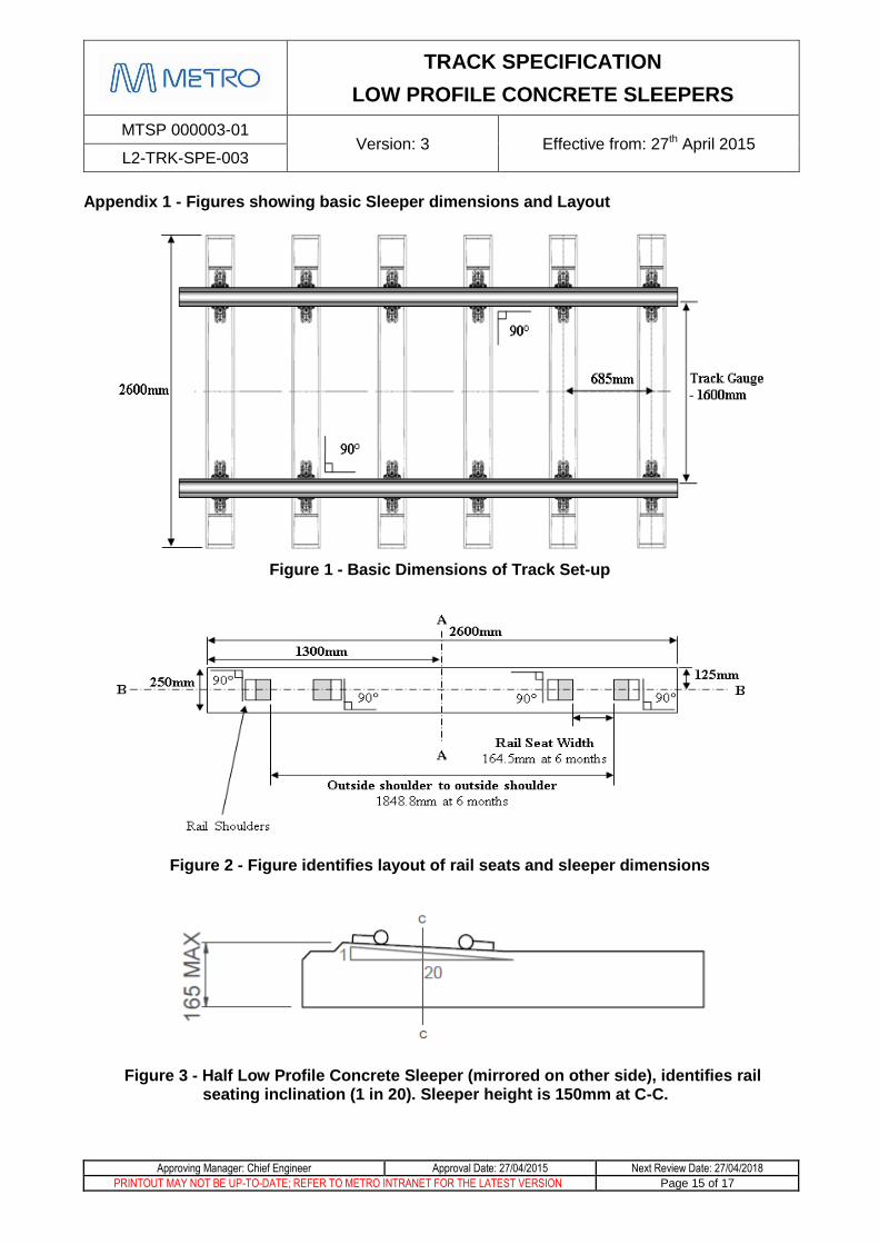
Appendix 1 - Figures showing basic Sleeper dimensions and Layout
Figure 1 - Basic Dimensions of Track Set-up
Figure 2 - Figure identifies layout of rail seats and sleeper dimensions
Figure 3 - Half Low Profile Concrete Sleeper (mirrored on other side), identifies rail seating inclination (1 in 20). Sleeper height is 150mm at C-C.
TRACK SPECIFICATION
LOW PROFILE CONCRETE SLEEPERS
MTSP 000003-01 Version: 3 Effective from: 27th April 2015
L2-TRK-SPE-003
Approving Manager: Chief Engineer Approval Date: 27/04/2015 Next Review Date: 27/04/2018
PRINTOUT MAY NOT BE UP-TO-DATE; REFER TO METRO INTRANET FOR THE LATEST VERSION Page 16 of 17
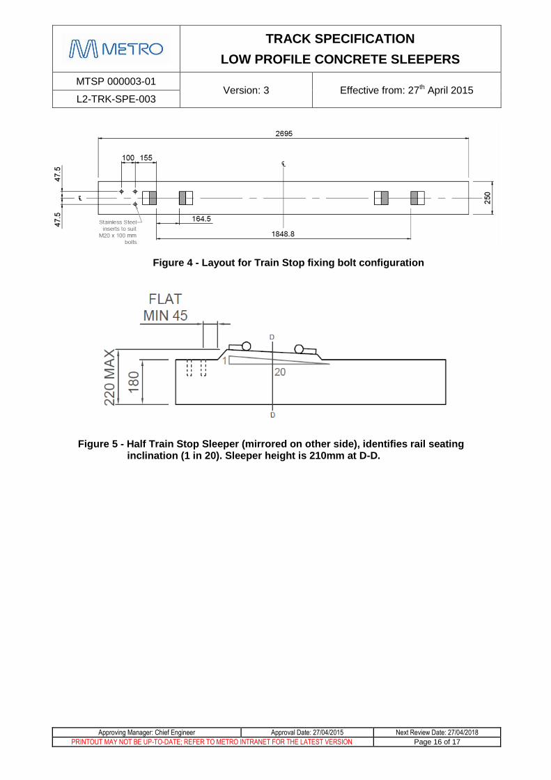
Figure 4 - Layout for Train Stop fixing bolt configuration
Figure 5 - Half Train Stop Sleeper (mirrored on other side), identifies rail seating inclination (1 in 20). Sleeper height is 210mm at D-D.
TRACK SPECIFICATION
LOW PROFILE CONCRETE SLEEPERS
MTSP 000003-01 Version: 3 Effective from: 27th April 2015
L2-TRK-SPE-003
Approving Manager: Chief Engineer Approval Date: 27/04/2015 Next Review Date: 27/04/2018
PRINTOUT MAY NOT BE UP-TO-DATE; REFER TO METRO INTRANET FOR THE LATEST VERSION Page 17 of 17
Appendix 2 - Current MTM Accepted Fastening Systems
Fastclip FE
Pandrol Type E-2003 Fastener
Recommended