TORRIX
Magnetostrictive level sensor
Sensors & Systems Worldwide: www.fafnir.com
Precision
Versatility
Security
PrecisionPrecision
Security
Versatility

2 | FAFNIR – Quality and Satisfaction
FAFNIR – Quality and Satisfaction
Quality for your Satisfaction:
To provide all our customers with consistently high quality products, FAFNIR has been ope-rating an internationally recognised, compre-hensive quality management system compliant with ISO 9001 (EN 29001) for many years. Our expertise in the development and manufacture of explosion-proof equipment is certified by an independent body. All our products are subject to strict FAFNIR quality requirements. We are committed to meeting international standards and applicable EU directives.
Company:
Based in Hamburg, Germany, FAFNIR GmbH has over 45 years of experience in the development and production of filling safety devices, overfill prevention devices, limit signal controllers and continuous level gauging solutions for all types of liquids. The optimisation of process controls, improve-ments in cost-efficiency and the protection of people and the environment are at the heart of our business.Our close and trusting relationship with our customers is a key factor in the practice- orientated implementation of innovative ideas and the functionality of our products.

| 3Contents
ContentsTORRIX
For precision level gauging 4
Application and measuring principle 5
Technical data
TORRIX 6
TORRIX 6 7
Floats and process connections 8
TORRIX Bypass 9
Accessories
HPH Ex d 10
UM-X 11

4 | TORRIX – For precision level gauging
TORRIXFor precision level gauging
The TORRIX level sensor operates on the high precision magnetostrictive measuring principle. This enables it to achieve an accuracy of up to ± 0.3 mm, placing it among the best in its class. Designed to provide continuous level gauging, TORRIX is integral to the quality assurance and safety of your process. TORRIX is compatible with all liquid media, but is particularly suited to level gauging applications that require a high degree of precision.
Tried and tested in the following industries:
Chemical, petrochemical, liquid gas, pharmaceu-tical, laboratory, off-shore, ship building, power plants, energy systems, mechanical engineering, treatment of process water and drinking water.
Easy to install and set up Maintenance-free Simultaneous measurement
of the separation layer and the level via HART®
Temperature-compensated measuring principle
2-wire terminal (4 to 20 mA) HART® protocol Short measuring intervals
(50 measurements per second)
Durability due to robust construction
Shock and vibration-proof Measuring range freely
adjustable along the entire probe length
Application in Ex-zone 0 (ATEX, IECEx certificate)
Benefits of FAFNIR technology
Quality assurance
and safety in
your process!
date
of
issu
e 0
7.1
1
Su
bje
ct t
o t
ech
nic
al ch
an
ge

| 5TORRIX – Application and measuring principle
TORRIXApplication and measuring principle
Measuring principle
The TORRIX probe tube contains a tensioned wire (1) made of magnetostrictive material. The sensor electronics transmit current pulses (2) through the wire, which generate a circular magnetic field (3). A magnet (4) contained in the float acts as the level sensor. The superposition of the two magnetic fields produces a torsional wave (5) at the float position, which then propagates along the wire. The time between the current pulse being transmitted and the wave arriving at the sensor head is measured. From these propagati-on times, it is possible to determine the current position of the float.
2
3
5
4
1
5
Application
The level sensor‘s uncomplicated, float-based operating principle makes it compatible with a very wide range of applications. Levels can be gauged regardless of whether the media under-go any physical or chemical change of state.Changes in conductivity or permittivity have no impact on the measurement. Even bubble or foam formation, rising vapours or condensation and changes in process pressure or process temperature have no effect on measuring accuracy. Separation layers and total filling le-vels are both measurable.Adjustment of the measuring probe according to liquid or the container type is not necessary, which eliminates the cost of a justification when liquid is changed.If the accuracy of your reed switch sensor no longer meets your requirements, our TORRIX probe offers an outstanding alternative – we can usually provide a sensor with the same dimensions, float and process connection as your existing sensor.
date
of
issu
e 0
7.1
1
Su
bje
ct t
o t
ech
nic
al ch
an
ge

6 | TORRIX – Technical data
Name TORRIX TORRIX flange
Technical drawing
Housing cover
Housing
Probe tube Ø 12
Cable gland
Ground connection
Screw-in unit G ½ WAF 27
11
2
Ø 50
52
Housing cover
Housing
Cable gland
Ground connection
11
2
Ø 50
Probe tube Ø 12
106
Process connection* Height adjustable with screw-in unit: all common threads
Welded: all common threads and flanges
Probe head
Protection class IP68
Material Standard: stainless steel 303; optional: stainless steel 316 L
Cable connection M16 x 1.5 cable gland for cable diameter 5 to 10 mm;optional: ½” NPT-thread for conduit connection; M12 connector
Ambient temperature - 40 °C to + 85 °C
Probe tube
Material Standard: stainless steel 316 Ti; optional: stainless steel 316 L, Hastelloy, titanium, tantalum, stainless steel 316 Ti coated
Diameter 12 mm
Length 200 mm to 6,000 mmHighest-temperature versions up to 3,000 mm
Options Vibration-resistant version, e.g. for use on tank trucks
Accuracy
Fill level ± 0.5 mm or ± 0.025 %, optional ± 0.3 mm or ± 0.01 %
Resolution 0.1 mm
Electrical connection
Connection 2-wire
Voltage 8 to 30 VDC
, Ex-version 10 to 30 VDC
Binary signal Current output: 4 to 20 mA; optional: HART®
HART® functions Float position in mm, cm, m, inches or feet; positioning of second float; separation layer (difference between floats); sensorstatus-information
Approvals Optional: ATEX, IECEx approval
Process conditions
Temperature Normal temperature (NT): - 40 °C to + 125 °CHigh temperature (HT): - 40 °C to + 250 °CHighest temperature (HHT): - 40 °C to + 450 °CLow temperature (LT): - 65 °C to + 125 °C
Pressure** 0 bar to 120 bar (room temperature)0 bar to 95 bar (250 °C)0 bar to 82 bar (450 °C)
Options Material and calibration certificate
* See order information page 8. ** Higher pressure range on request.
TORRIXTechnical data
date
of
issu
e 0
7.1
1
Su
bje
ct t
o t
ech
nic
al ch
an
ge

| 7TORRIX 6 – Technical data
Name TORRIX 6 TORRIX 6 B
Technical drawing
Ground connection
Probe tube Ø 6
M12 connector1
12
Ø 50
Housing cover
Probe tube Ø 6
Ground connection
Ø 50
11
6
M12 connector
Housing cover
Process connection* Height adjustable with screw-in unit: all common threads.Bottle caps for all common laboratory bottles, e.g. GL45
Probe head
Protection class IP68
Material Standard: stainless steel 303; optional: stainless steel 316 L
Cable connection M16 x 1.5 screwed cable gland for cable diameter 5 to 10 mm;optional: M12 connector (see drawing)
Ambient temperature - 40 °C to + 85 °C
Probe tube
Material Standard: stainless steel 316 Ti; optional: stainless steel 316 L, Hastelloy, titanium, tantalum
Diameter 6 mm
Length 200 mm to 1,000 mm
Accuracy
Fill level 0.75 mm or ± 0.025 %
Resolution 0.1 mm
Electrical connection
Connection 2-wire
Voltage 8 to 30 VDC
, Ex-version 10 to 30 VDC
Binary signal Current output: 4 to 20 mA; optional: HART®
HART® functions Float position in mm, cm, m, inches or feet; sensor status information
Approvals Optional: ATEX, IECEx approval
Process conditions
Temperature Normal temperature (NT): - 40 °C to + 125 °C
Options Material and calibration certificate
Float** External diameter: 27 mm;for media with a density < 0.75 g/mm³;Process pressure max. 19 bar
* See order information page 8. ** Other floats on request.
TORRIX 6Technical data
date
of
issu
e 0
7.1
1
Su
bje
ct t
o t
ech
nic
al ch
an
ge

8 | Floats and process connections
Floats and process connections
For mediumdensity
Float density
Temperature range
Max.operating pressure
Dimensions in mmShape
Order number
A H C
Stainless steel 316 Ti
≥ 0.95 g/cm³ < 0.85 g/cm³ - 200 °C to + 250 °C 50 bar 43.0 40.0 15.0 Sphere 909115
≥ 0.85 g/cm³ < 0.75 g/cm³ - 200 °C to + 250 °C 20 bar 43.0 40.0 15.5 Sphere 909130
≥ 0.70 g/cm³ < 0.60 g/cm³ - 200 °C to + 250 °C 40 bar 52.0 52.0 15.5 Sphere 900013
≥ 0.60 g/cm³ < 0.50 g/cm³ - 200 °C to + 250 °C 20 bar 52.0 49.0 15.5 Sphere 909109
≥ 0.45 g/cm³ < 0.36 g/cm³ - 40 °C to + 250 °C 25 bar 83.0 82.0 15.0 Sphere 909229
≥ 0.70 g/cm³ < 0.60 g/cm³ - 200 °C to + 250 °C 16 bar 43.0 43.0 15.5 Cylinder 909119
≥ 0.70 g/cm³ < 0.60 g/cm³ - 200 °C to + 250 °C 5 bar 29.5 40.0 12.5 Cylinder 908495
≥ 0.70 g/cm³ < 0.60 g/cm³ - 200 °C to + 250 °C 1 bar 29.5 40.0 12.5 Cylinder 908528
TITANIUM
≥ 0.50 g/cm³ < 0.40 g/cm³ - 200 °C to + 250 °C 20 bar 50.0 48.0 15.4 Sphere 909113
≥ 0.40 g/cm³ < 0.30 g/cm³ - 40 °C to + 125 °C 25 bar 83.0 81.0 15.0 Sphere 909140
≥ 0.50 g/cm³ < 0.42 g/cm³ - 40 °C to + 125 °C 25 bar 98.0 96.0 23.0 Sphere 909177
≥ 0.69 g/cm³ < 0.59 g/cm³ - 200 °C to + 450 °C 200 bar 60.0 59.0 14.5 Sphere 909205
Other fl oats on request.
FloatFloats (excerpt)
Process connections (excerpt)
Fittings, fl anges and threads
Description Material Thread Order number
Fitting for standard probes Ø 12 mm
Screw-in unit Brass R 1½ 909097
Screw-in unit 316 Ti G ½ 909092
Screw-in unit (Swagelok) 316 NPT ½“ 909117
Screw-in unit (Swagelok) 316 NPT ¾” 909228
Fitting for 6 mm probes
Screw-in unit 316 Ti G 3/8 909250
Laboratory bottle caps PTFE/PP GL45 905632
Canister caps PTFE/PP S60/S61 905633
Flange
2” ANSI, 150 lbs 316 Ti 909245
3” ANSI, 150 lbs 316 Ti 909237
DN 25, PN 6, DIN 2527, Form B 316 Ti 909238
DN 50, PN 16, DIN 2527, Form C 316 Ti 909243
DN 65, PN 16, DIN 2527, Form C 316 Ti 909247
Other fi ttings and fl anges on request. date of issue 07.11 Subject to technical change
Ø C
Ø A
Ø C
Ø A
HH

| 9TORRIX Bypass – Technical data
TORRIX BypassTechnical data
Name TORRIX Bypass
Technical drawing
Probe tube Ø 12
Ø 50
11
6
Ground connection
Screwed cable gland
Housing cover
Process connection None, for installation on a magnetic level indicator
Probe head
Protection class IP68
Material Standard: stainless steel 303; optional: stainless steel 316 L
Cable connection M16 x 1.5 cable gland for cable diameter 5 to 10 mm;optional: ½” NPT for conduit connection; M12 connector
Ambient temperature - 40 °C to + 85 °C
Probe tube
Material Standard: stainless steel 316 Ti; optional: stainless steel 316 L
Diameter 12 mm
Length 200 mm to 6,000 mmHighest-temperature versions up to 3,000 mm
Accuracy
Fill level Depending on bypass float, down to ± 0.5 mm
Resolution 0.1 mm
Electrical connection
Connection 2-wire
Voltage 8 to 30 VDC
, Ex-version 10 to 30 VDC
Binary signal Current output: 4 to 20 mA; optional: HART®
HART® functions Float position in mm, cm, m, inches or feet; sensorstatus-information
Approvals Optional: ATEX, IECEx approval
Process conditions
Temperature Normal temperature (NT): - 40 °C to + 125 °CHigh temperature (HT): - 40 °C to + 250 °CHighest temperature (HHT): - 40 °C to + 450 °CLow temperature (LT): - 65 °C to + 125 °C
Options Material and calibration certificate
date
of
issu
e 0
7.1
1
Su
bje
ct t
o t
ech
nic
al ch
an
ge
10 | d
Accessories
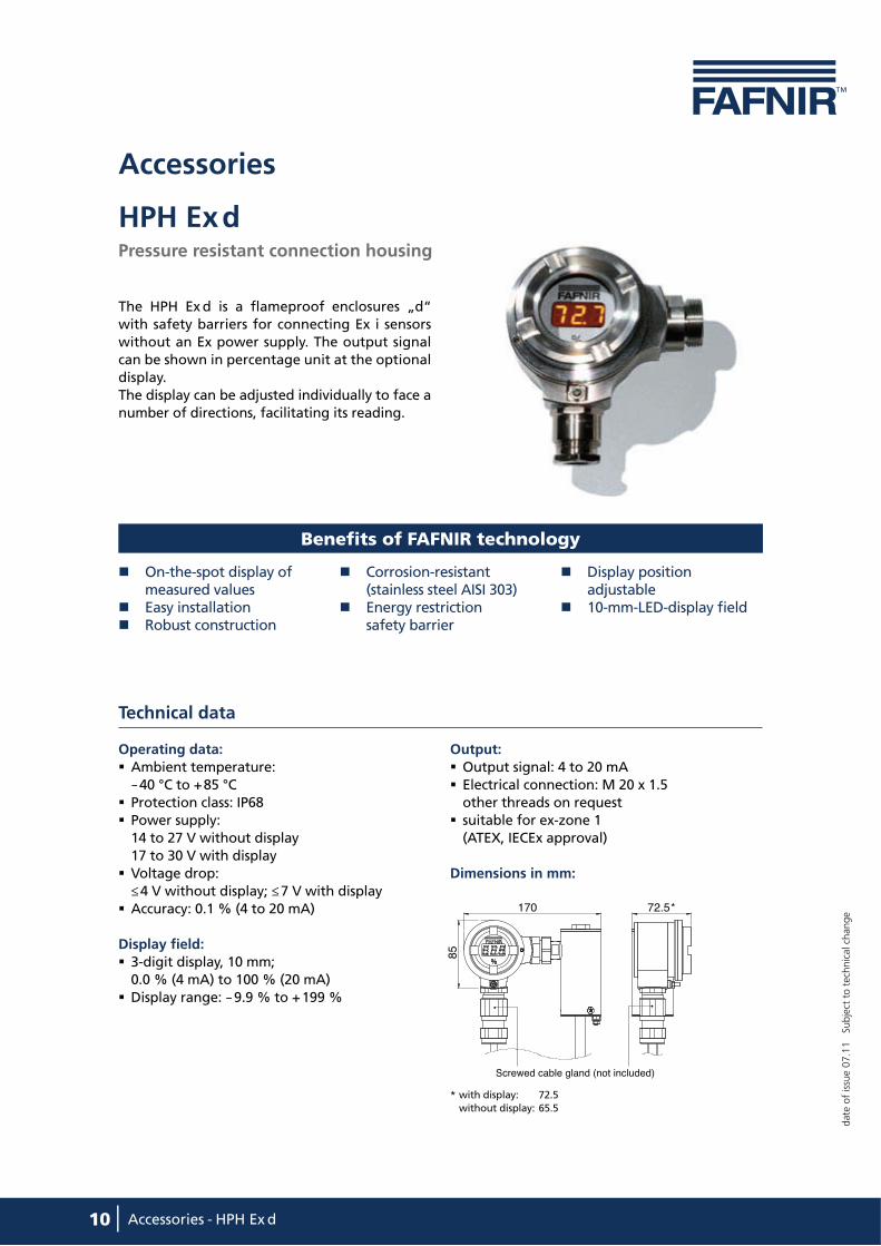
HPH Ex d Pressure resistant connection housing
The HPH Ex d is a flameproof enclosures „d“ with safety barriers for connecting Ex i sensors with out an Ex power supply. The output signal can be shown in percentage unit at the optional display.The display can be adjusted individually to face a number of directions, facilitating its reading.
On-the-spot display of measured values
Easy installation Robust construction
Corrosion-resistant (stainless steel AISI 303)
Energy restriction safety barrier
Display position adjustable
10-mm-LED-display field
Technical data
Operating data:
Ambient temperature: - 40 °C to + 85 °C
Protection class: IP68 Power supply: 14 to 27 V without display 17 to 30 V with display
Voltage drop: ≤ 4 V without display; ≤ 7 V with display
Accuracy: 0.1 % (4 to 20 mA)
Display field:
3-digit display, 10 mm; 0.0 % (4 mA) to 100 % (20 mA)
Display range: - 9.9 % to + 199 %
Output:
Output signal: 4 to 20 mA Electrical connection: M 20 x 1.5 other threads on request
suitable for ex-zone 1 (ATEX, IECEx approval)
Dimensions in mm:
Benefits of FAFNIR technology
72.5*170
85
Screwed cable gland (not included)
* with display: 72.5
without display: 65.5
date
of
issu
e 0
7.1
1
Su
bje
ct t
o t
ech
nic
al ch
an
ge
Accessories - HPH Ex
| 11Accessories – UM-X
Accessories
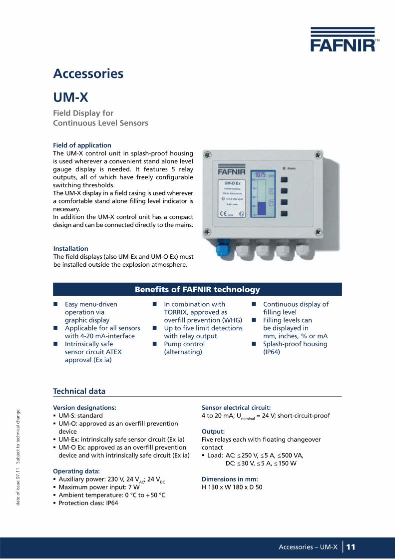
UM-X Field Display for
Continuous Level Sensors
Field of applicationThe UM-X control unit in splash-proof housing is used wherever a convenient stand alone level gauge display is needed. It features 5 relay outputs, all of which have freely configurable switching thresholds.The UM-X display in a field casing is used wherever a comfortable stand alone filling level indicator is necessary.In addition the UM-X control unit has a compact design and can be connected directly to the mains.
Benefits of FAFNIR technology
InstallationThe field displays (also UM-Ex and UM-O Ex) must be installed outside the explosion atmosphere.
Technical data
Version designations:
UM-S: standard UM-O: approved as an overfill prevention device
UM-Ex: intrinsically safe sensor circuit (Ex ia) UM-O Ex: approved as an overfill prevention device and with intrinsically safe circuit (Ex ia)
Operating data:
Auxiliary power: 230 V, 24 VAC
; 24 VDC
Maximum power input: 7 W Ambient temperature: 0 °C to + 50 °C Protection class: IP64
Sensor electrical circuit:
4 to 20 mA; Unominal
= 24 V; short-circuit-proof
Output: Five relays each with floating changeover contact Load: AC: ≤ 250 V, ≤ 5 A, ≤ 500 VA, DC: ≤ 30 V, ≤ 5 A, ≤ 150 W
Dimensions in mm:
H 130 x W 180 x D 50
Easy menu-driven operation via graphic display
Applicable for all sensors with 4-20 mA-interface
Intrinsically safe sensor circuit ATEX approval (Ex ia)
In combination with TORRIX, approved as overfill prevention (WHG)
Up to five limit detections with relay output
Pump control (alternating)
Continuous display of filling level
Filling levels can be displayed in mm, inches, % or mA
Splash-proof housing (IP64)
date
of
issu
e 0
7.1
1
Su
bje
ct t
o t
ech
nic
al ch
an
ge
Sensors & Systems Worldwide: www.fafnir.com
FAFNIR GmbH
Bahrenfelder Straße 19
22765 Hamburg, Germany
Phone: +49/40/39 82 07-0
Fax: +49/40/390 63 39
E-mail: [email protected]
Internet: www.fafnir.com
Recommended