TORNADO INDUSTRIES7401 W. LAWRENCE AVENUE
CHICAGO, IL 60706(708) 867-5100 FAX (708) 867-6968
www.tornadovac.com
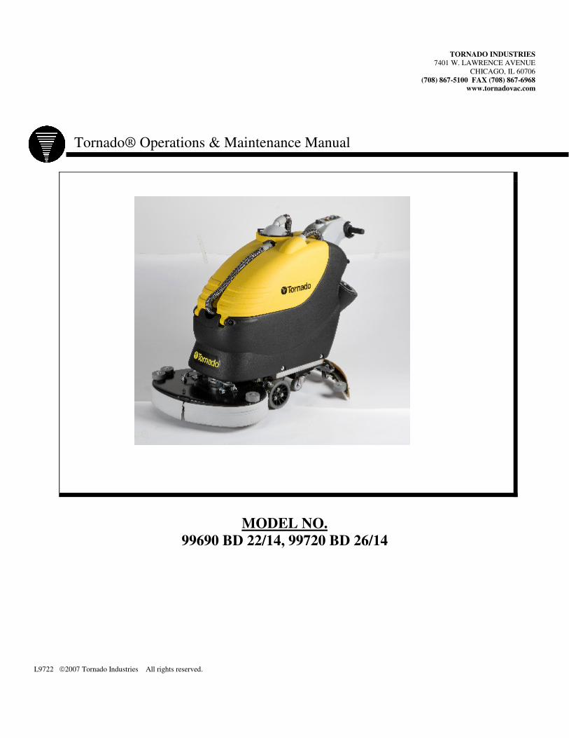
Tornado® Operations & Maintenance Manual
MODEL NO.99690 BD 22/14, 99720 BD 26/14
L9722 �2007 Tornado Industries All rights reserved.
�
TABLE OF CONTENTS
WARRANTY 2INSTRUMENT BOARD AND CONTROLS �MACHINE �PRODUCT SPECIFICATIONS �Model �INTRODUCTORY COMMENT �GENERAL RULES �SYMBOLS �BEFORE USE ����� ���������� �� �������� ������ ���������� ����������������� �������������� �������������� �� ��������� ���� �������������������� �� ���� ����������� !"�������������� #�$���������%������"������ !���������������� ������������� &����������� '(�������������� ������ '
FLOOR CLEANING ')������ ����%���������� ������������� �� '!��� ���������� �� '*��+����������� ',��� ������� '-������������� '#�$���������%������������������ .�������������������������� ������ �� ./���%��+���� �� .
STOPPING THE MACHINE AFTER CLEANING OPERATION .DAILY MAINTENANCE .&���������������� �� .!��� ���% ��������� �� .���������� �� .������� �������� .!"����������� �� �0
WEEKLY MAINTENANCE �0&����"����������������������� �0!"���������������� �� �0)��� �������� ����������% ���� �0
TWO-MONTHLY MAINTENANCE �0*������"����������������������� �0
SIX-MONTH MAINTENANCE ��!������������������ ��)����1����������� ��
TROUBLESHOOTING GUIDE ��! ������������� ��� ��2���3��������������������+��� ��2������������������������+��� ��2������� ������������������+��� ��1���%% � ����+������������������ �45�� ����������������������� �4!"�������������������������� �4-6���� ���%��������� �� �4
4
�
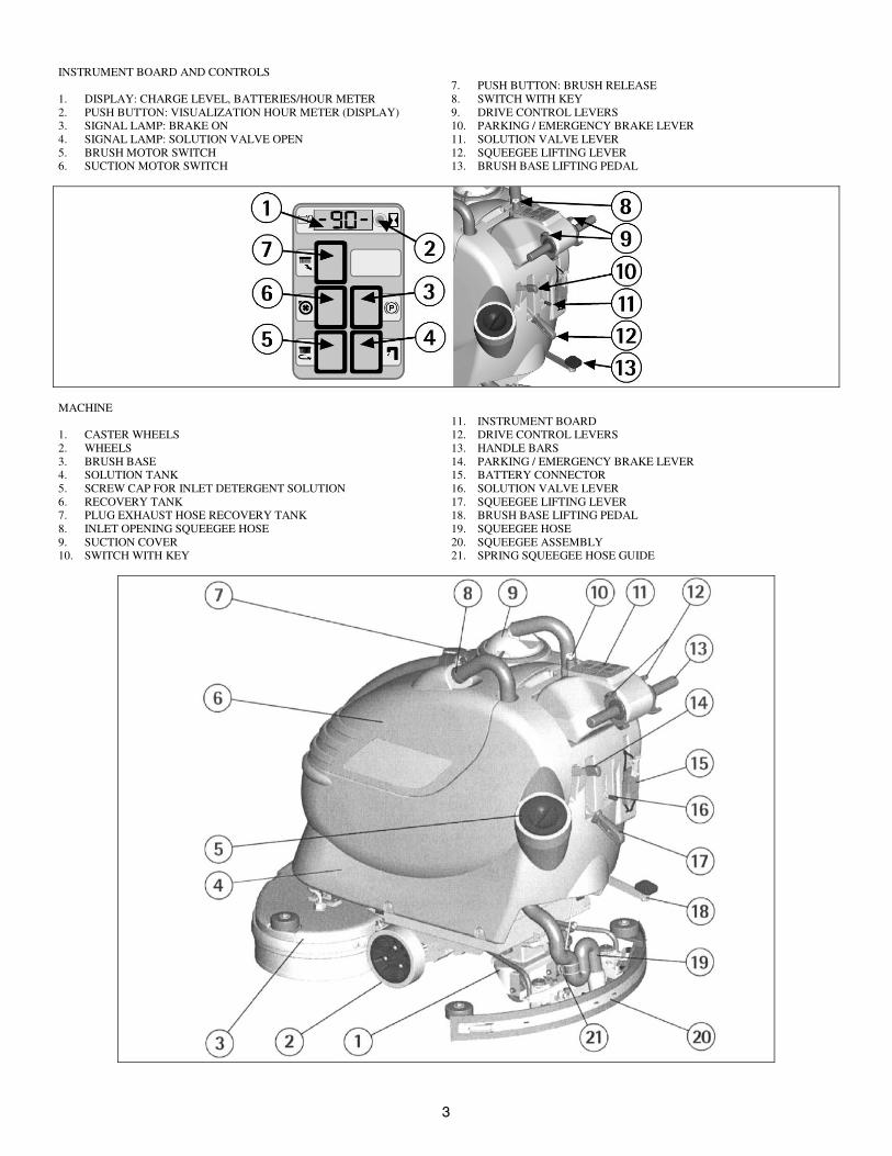
INSTRUMENT BOARD AND CONTROLS
1. DISPLAY: CHARGE LEVEL, BATTERIES/HOUR METER2. PUSH BUTTON: VISUALIZATION HOUR METER (DISPLAY)3. SIGNAL LAMP: BRAKE ON4. SIGNAL LAMP: SOLUTION VALVE OPEN5. BRUSH MOTOR SWITCH6. SUCTION MOTOR SWITCH
7. PUSH BUTTON: BRUSH RELEASE8. SWITCH WITH KEY9. DRIVE CONTROL LEVERS10. PARKING / EMERGENCY BRAKE LEVER11. SOLUTION VALVE LEVER12. SQUEEGEE LIFTING LEVER13. BRUSH BASE LIFTING PEDAL
MACHINE
1. CASTER WHEELS2. WHEELS3. BRUSH BASE4. SOLUTION TANK5. SCREW CAP FOR INLET DETERGENT SOLUTION6. RECOVERY TANK7. PLUG EXHAUST HOSE RECOVERY TANK8. INLET OPENING SQUEEGEE HOSE9. SUCTION COVER10. SWITCH WITH KEY
11. INSTRUMENT BOARD12. DRIVE CONTROL LEVERS13. HANDLE BARS14. PARKING / EMERGENCY BRAKE LEVER15. BATTERY CONNECTOR16. SOLUTION VALVE LEVER17. SQUEEGEE LIFTING LEVER18. BRUSH BASE LIFTING PEDAL19. SQUEEGEE HOSE20. SQUEEGEE ASSEMBLY21. SPRING SQUEEGEE HOSE GUIDE
�
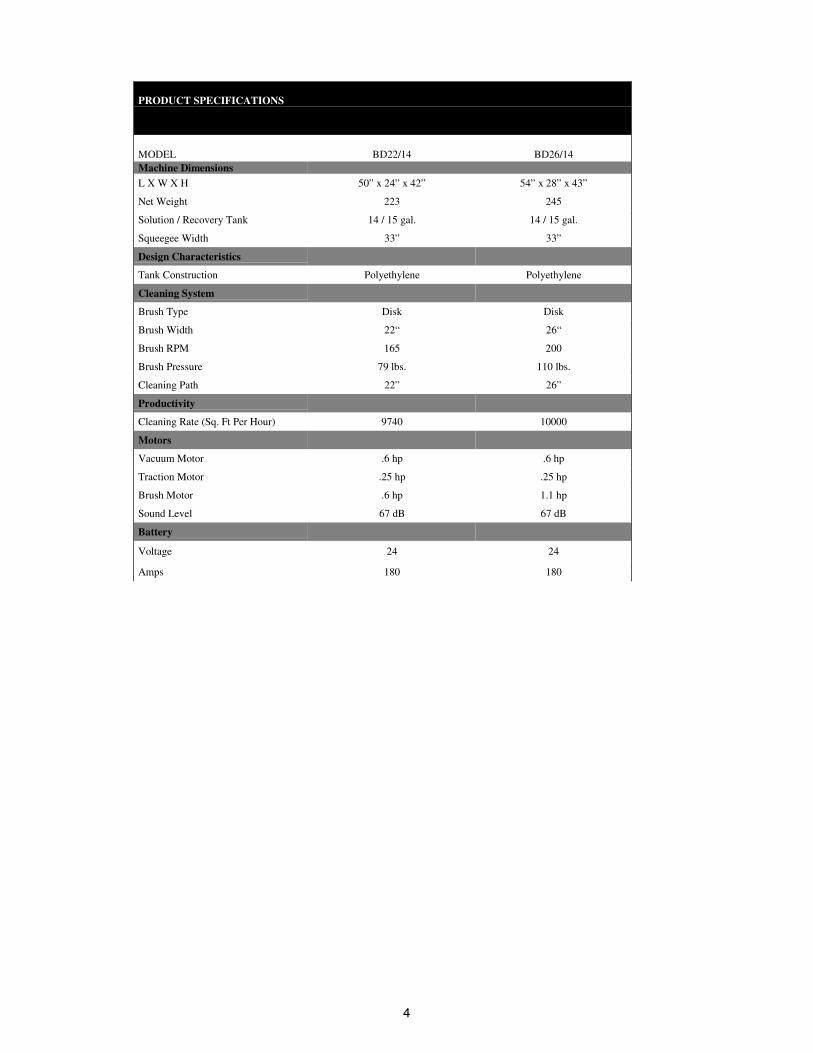
PRODUCT SPECIFICATIONS
MODEL BD22/14 BD26/14Machine DimensionsL X W X H 50” x 24” x 42” 54” x 28” x 43”
Net Weight 223 245
Solution / Recovery Tank 14 / 15 gal. 14 / 15 gal.
Squeegee Width 33” 33”
Design Characteristics
Tank Construction Polyethylene Polyethylene
Cleaning System
Brush Type Disk Disk
Brush Width 22“ 26“
Brush RPM 165 200
Brush Pressure 79 lbs. 110 lbs.
Cleaning Path 22” 26”
Productivity
Cleaning Rate (Sq. Ft Per Hour) 9740 10000
Motors
Vacuum Motor .6 hp .6 hp
Traction Motor .25 hp .25 hp
Brush Motor .6 hp 1.1 hp
Sound Level 67 dB 67 dB
Battery
Voltage 24 24
Amps 180 180
�
INTRODUCTORY COMMENTThank you for choosing our machine. Thisfloor-cleaning machine is used for industrial andcommercial cleaning and is able to clean anytype of floor. During its forward movement, theaction of the brush and the detergent solutionremoves the dirt, which is picked up by thesuction system, resulting in a dry surface.The machine must be used only for this purpose.It gives the best performance when it usedcorrectly and maintained properly. Therefore,we ask that you read this instruction bookletcarefully whenever difficulties arise in thecourse of the machine’s use. If needed, pleasecontact our service department for advice and/orservice.
GENERAL RULESThe rules below have to be followed carefully inorder to avoid damage to the machine andinjuries to the operator.- Read the labels carefully on the machine. Donot cover them for any reason and replace themimmediately if damaged.- The machine must be used exclusively byauthorized staff that has been instructed for itsuse.- When using the machine, pay attention toother people, especially children.- In case of danger, immediately use theemergency brake.- To park the machine, take off the key and puton the parking brake.- Do not mix different detergents to avoidharmful odors.- Do not place any liquid containers onto themachine.- The storage temperature has to be between -13°F and +131°F.- The operating temperature should be between32°F and 104°F.- The humidity should be between 30 and 95%.- Do not use the machine in an explosiveatmosphere.- Do not use the machine as a means oftransportation.- Do not use acidic solutions, which coulddamage the machine and/or injure people.- Do not use the machine on surfaces coveredwith flammable liquids or dust (for examplehydrocarbons, ashes or soot).- In case of fire, use a powder fire-extinguisher.Do not use water.- Watch out for shelves and/or scaffoldingswhen operating the machine.- Use the appropriate speed based on floorconditions (type of floor, dirtiness, etc.).- Do not use the machine on areas that have ahigher gradient than the one stated on thenumber plate.- The machine has to carry out simultaneouslythe operations of washing and drying. Differentoperations must be carried out in restricted areasprohibited to non-authorized personnel.- Signal the areas of moist floors with suitablesigns.- If the machine does not work properly, checkby conducting simple maintenance procedures.Otherwise, contact an authorized technicalassistant for advice.- When parts are required, ask for ORIGINALspare parts from the distributor or an authorizeddealer.- Use only ORIGINAL brushes.- When cleaning and performing maintenanceoperations, disconnect the power supply plugfrom the machine.
- Do not wash the machine with corrosivematerial, direct water jets or high waterpressure.- Every 200 working hours, have the machinechecked by an authorized service center.- In order to avoid scales on the solution tankfilter, do not fill the detergent solution hoursbefore it is used.- Before using the machine, check that allpanels and coverings are in position as indicatedin this use and maintenance catalog.- Be sure the recovery tank is empty beforelifting it.- Restore all electrical connections after anymaintenance operation.- When your machine has to stop activity,provide the appropriate waste disposal for itsmaterials, especially oils, battery and electroniccomponents. Consider that the machine itselfhas been constructed by recyclable materials.
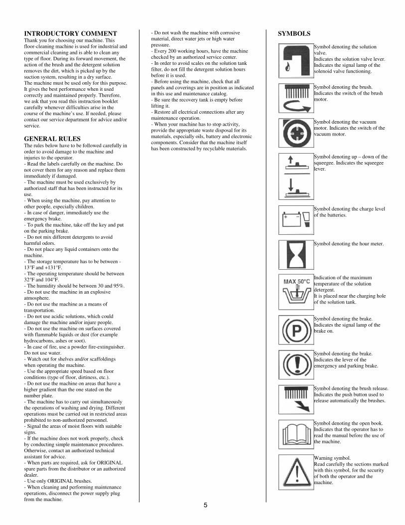
SYMBOLS
Symbol denoting the solutionvalve.Indicates the solution valve lever.Indicates the signal lamp of thesolenoid valve functioning.
Symbol denoting the brush.Indicates the switch of the brushmotor.
Symbol denoting the vacuummotor. Indicates the switch of thevacuum motor.
Symbol denoting up – down of thesqueegee. Indicates the squeegeelever.
Symbol denoting the charge levelof the batteries.
Symbol denoting the hour meter.
Indication of the maximumtemperature of the solutiondetergent.It is placed near the charging holeof the solution tank.
Symbol denoting the brake.Indicates the signal lamp of thebrake on.
Symbol denoting the brake.Indicates the lever of theemergency and parking brake.
Symbol denoting the brush release.Indicates the push button used torelease automatically the brushes.
Symbol denoting the open book.Indicates that the operator has toread the manual before the use ofthe machine.
Warning symbol.Read carefully the sections markedwith this symbol, for the securityof both the operator and themachine.
�
BEFORE USE
The machine is supplied with suitable packingfor forklift truck handling.The total weight is 269 lbs.Packing dimensions:Base: 54.13 in x 26.18 inHeight: 46.65 in.
ATTENTION:Do not place more than 2 pallets on top ofeach other.
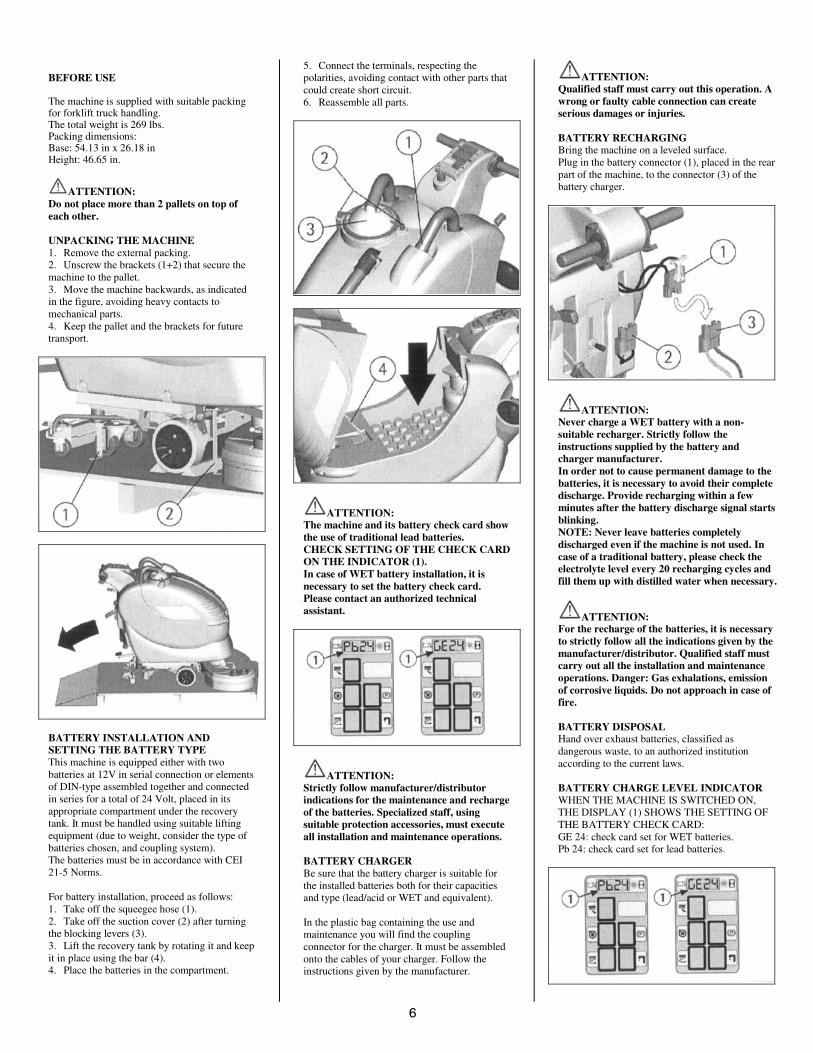
UNPACKING THE MACHINE1. Remove the external packing.2. Unscrew the brackets (1+2) that secure themachine to the pallet.3. Move the machine backwards, as indicatedin the figure, avoiding heavy contacts tomechanical parts.4. Keep the pallet and the brackets for futuretransport.
BATTERY INSTALLATION ANDSETTING THE BATTERY TYPEThis machine is equipped either with twobatteries at 12V in serial connection or elementsof DIN-type assembled together and connectedin series for a total of 24 Volt, placed in itsappropriate compartment under the recoverytank. It must be handled using suitable liftingequipment (due to weight, consider the type ofbatteries chosen, and coupling system).The batteries must be in accordance with CEI21-5 Norms.
For battery installation, proceed as follows:1. Take off the squeegee hose (1).2. Take off the suction cover (2) after turningthe blocking levers (3).3. Lift the recovery tank by rotating it and keepit in place using the bar (4).4. Place the batteries in the compartment.
5. Connect the terminals, respecting thepolarities, avoiding contact with other parts thatcould create short circuit.6. Reassemble all parts.
ATTENTION:The machine and its battery check card showthe use of traditional lead batteries.CHECK SETTING OF THE CHECK CARDON THE INDICATOR (1).In case of WET battery installation, it isnecessary to set the battery check card.Please contact an authorized technicalassistant.
ATTENTION:Strictly follow manufacturer/distributorindications for the maintenance and rechargeof the batteries. Specialized staff, usingsuitable protection accessories, must executeall installation and maintenance operations.
BATTERY CHARGERBe sure that the battery charger is suitable forthe installed batteries both for their capacitiesand type (lead/acid or WET and equivalent).
In the plastic bag containing the use andmaintenance you will find the couplingconnector for the charger. It must be assembledonto the cables of your charger. Follow theinstructions given by the manufacturer.
ATTENTION:Qualified staff must carry out this operation. Awrong or faulty cable connection can createserious damages or injuries.
BATTERY RECHARGINGBring the machine on a leveled surface.Plug in the battery connector (1), placed in the rearpart of the machine, to the connector (3) of thebattery charger.
ATTENTION:Never charge a WET battery with a non-suitable recharger. Strictly follow theinstructions supplied by the battery andcharger manufacturer.In order not to cause permanent damage to thebatteries, it is necessary to avoid their completedischarge. Provide recharging within a fewminutes after the battery discharge signal startsblinking.NOTE: Never leave batteries completelydischarged even if the machine is not used. Incase of a traditional battery, please check theelectrolyte level every 20 recharging cycles andfill them up with distilled water when necessary.
ATTENTION:For the recharge of the batteries, it is necessaryto strictly follow all the indications given by themanufacturer/distributor. Qualified staff mustcarry out all the installation and maintenanceoperations. Danger: Gas exhalations, emissionof corrosive liquids. Do not approach in case offire.
BATTERY DISPOSALHand over exhaust batteries, classified asdangerous waste, to an authorized institutionaccording to the current laws.
BATTERY CHARGE LEVEL INDICATORWHEN THE MACHINE IS SWITCHED ON,THE DISPLAY (1) SHOWS THE SETTING OFTHE BATTERY CHECK CARD:GE 24: check card set for WET batteries.Pb 24: check card set for lead batteries.
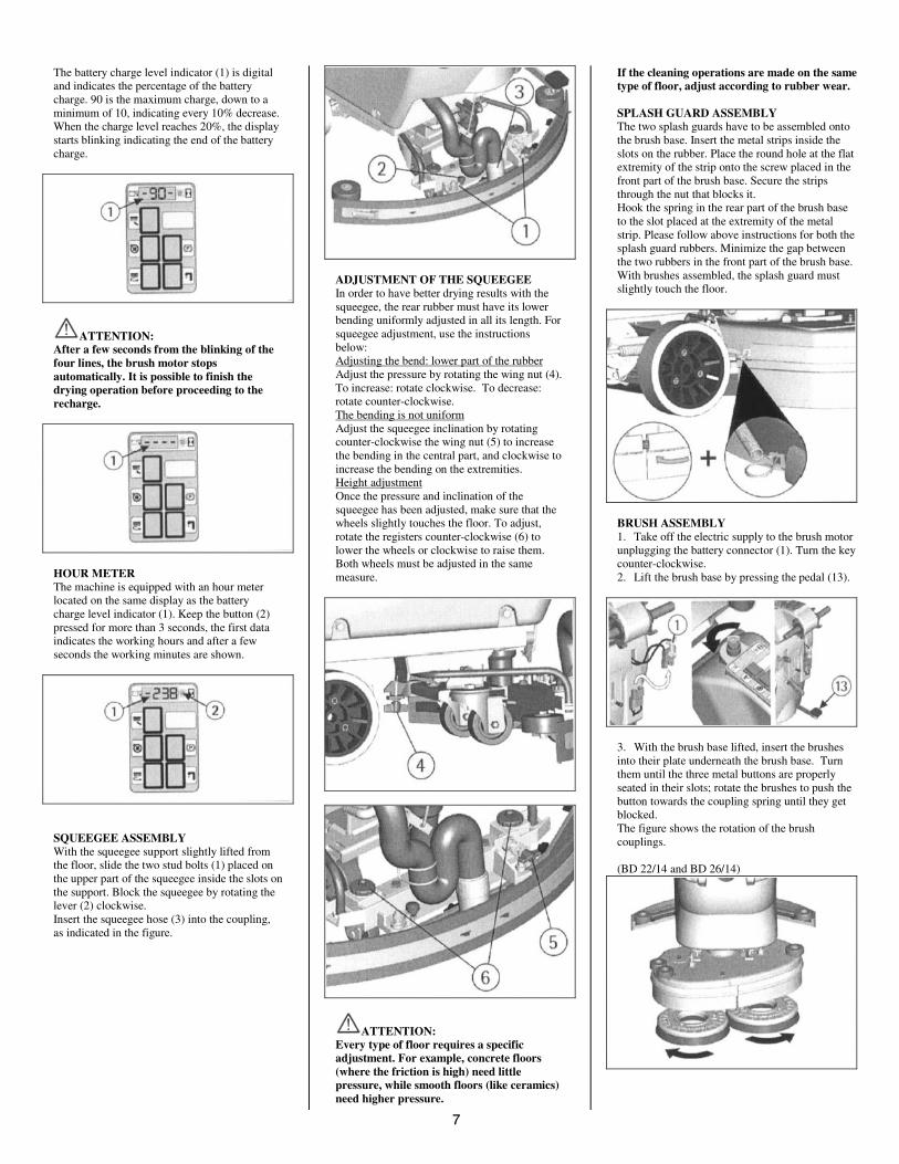
The battery charge level indicator (1) is digitaland indicates the percentage of the batterycharge. 90 is the maximum charge, down to aminimum of 10, indicating every 10% decrease.When the charge level reaches 20%, the displaystarts blinking indicating the end of the batterycharge.
ATTENTION:After a few seconds from the blinking of thefour lines, the brush motor stopsautomatically. It is possible to finish thedrying operation before proceeding to therecharge.
HOUR METERThe machine is equipped with an hour meterlocated on the same display as the batterycharge level indicator (1). Keep the button (2)pressed for more than 3 seconds, the first dataindicates the working hours and after a fewseconds the working minutes are shown.
SQUEEGEE ASSEMBLYWith the squeegee support slightly lifted fromthe floor, slide the two stud bolts (1) placed onthe upper part of the squeegee inside the slots onthe support. Block the squeegee by rotating thelever (2) clockwise.Insert the squeegee hose (3) into the coupling,as indicated in the figure.
ADJUSTMENT OF THE SQUEEGEEIn order to have better drying results with thesqueegee, the rear rubber must have its lowerbending uniformly adjusted in all its length. Forsqueegee adjustment, use the instructionsbelow:Adjusting the bend: lower part of the rubberAdjust the pressure by rotating the wing nut (4).To increase: rotate clockwise. To decrease:rotate counter-clockwise.The bending is not uniformAdjust the squeegee inclination by rotatingcounter-clockwise the wing nut (5) to increasethe bending in the central part, and clockwise toincrease the bending on the extremities.Height adjustmentOnce the pressure and inclination of thesqueegee has been adjusted, make sure that thewheels slightly touches the floor. To adjust,rotate the registers counter-clockwise (6) tolower the wheels or clockwise to raise them.Both wheels must be adjusted in the samemeasure.
ATTENTION:Every type of floor requires a specificadjustment. For example, concrete floors(where the friction is high) need littlepressure, while smooth floors (like ceramics)need higher pressure.
If the cleaning operations are made on the sametype of floor, adjust according to rubber wear.
SPLASH GUARD ASSEMBLYThe two splash guards have to be assembled ontothe brush base. Insert the metal strips inside theslots on the rubber. Place the round hole at the flatextremity of the strip onto the screw placed in thefront part of the brush base. Secure the stripsthrough the nut that blocks it.Hook the spring in the rear part of the brush baseto the slot placed at the extremity of the metalstrip. Please follow above instructions for both thesplash guard rubbers. Minimize the gap betweenthe two rubbers in the front part of the brush base.With brushes assembled, the splash guard mustslightly touch the floor.
BRUSH ASSEMBLY1. Take off the electric supply to the brush motorunplugging the battery connector (1). Turn the keycounter-clockwise.2. Lift the brush base by pressing the pedal (13).
3. With the brush base lifted, insert the brushesinto their plate underneath the brush base. Turnthem until the three metal buttons are properlyseated in their slots; rotate the brushes to push thebutton towards the coupling spring until they getblocked.The figure shows the rotation of the brushcouplings.
(BD 22/14 and BD 26/14)
'
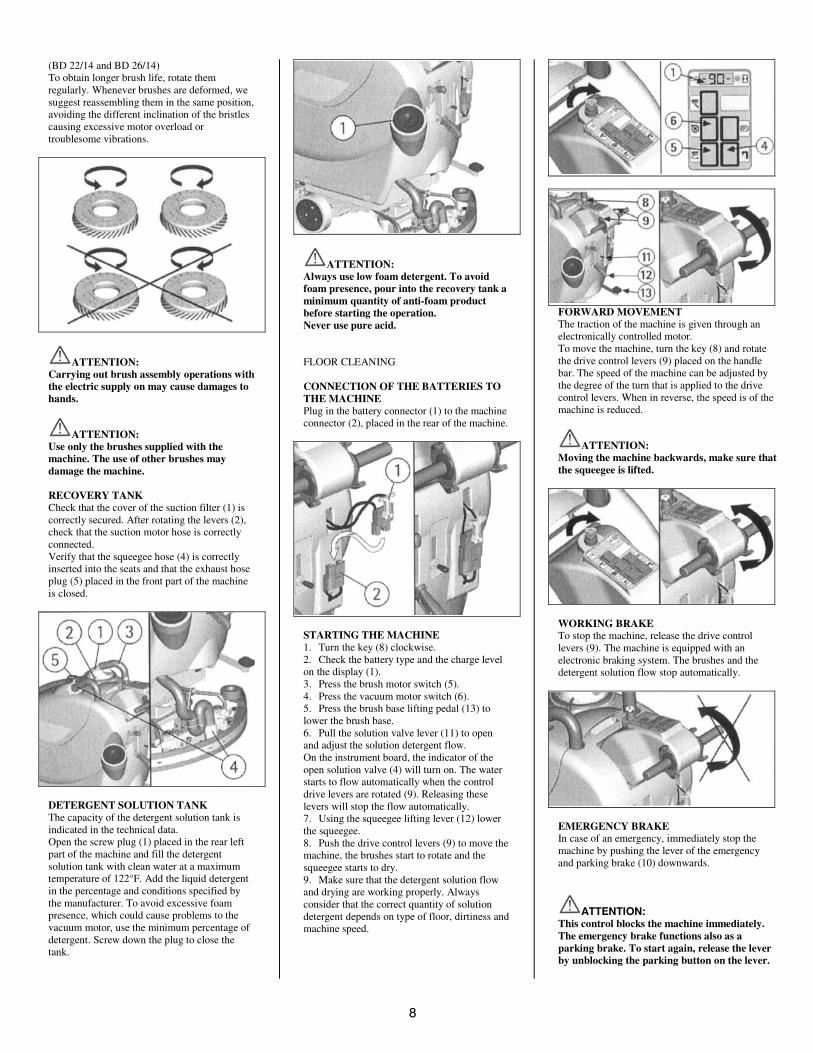
(BD 22/14 and BD 26/14)To obtain longer brush life, rotate themregularly. Whenever brushes are deformed, wesuggest reassembling them in the same position,avoiding the different inclination of the bristlescausing excessive motor overload ortroublesome vibrations.
ATTENTION:Carrying out brush assembly operations withthe electric supply on may cause damages tohands.
ATTENTION:Use only the brushes supplied with themachine. The use of other brushes maydamage the machine.
RECOVERY TANKCheck that the cover of the suction filter (1) iscorrectly secured. After rotating the levers (2),check that the suction motor hose is correctlyconnected.Verify that the squeegee hose (4) is correctlyinserted into the seats and that the exhaust hoseplug (5) placed in the front part of the machineis closed.
DETERGENT SOLUTION TANKThe capacity of the detergent solution tank isindicated in the technical data.Open the screw plug (1) placed in the rear leftpart of the machine and fill the detergentsolution tank with clean water at a maximumtemperature of 122°F. Add the liquid detergentin the percentage and conditions specified bythe manufacturer. To avoid excessive foampresence, which could cause problems to thevacuum motor, use the minimum percentage ofdetergent. Screw down the plug to close thetank.
ATTENTION:Always use low foam detergent. To avoidfoam presence, pour into the recovery tank aminimum quantity of anti-foam productbefore starting the operation.Never use pure acid.
FLOOR CLEANING
CONNECTION OF THE BATTERIES TOTHE MACHINEPlug in the battery connector (1) to the machineconnector (2), placed in the rear of the machine.
STARTING THE MACHINE1. Turn the key (8) clockwise.2. Check the battery type and the charge levelon the display (1).3. Press the brush motor switch (5).4. Press the vacuum motor switch (6).5. Press the brush base lifting pedal (13) tolower the brush base.6. Pull the solution valve lever (11) to openand adjust the solution detergent flow.On the instrument board, the indicator of theopen solution valve (4) will turn on. The waterstarts to flow automatically when the controldrive levers are rotated (9). Releasing theselevers will stop the flow automatically.7. Using the squeegee lifting lever (12) lowerthe squeegee.8. Push the drive control levers (9) to move themachine, the brushes start to rotate and thesqueegee starts to dry.9. Make sure that the detergent solution flowand drying are working properly. Alwaysconsider that the correct quantity of solutiondetergent depends on type of floor, dirtiness andmachine speed.
FORWARD MOVEMENTThe traction of the machine is given through anelectronically controlled motor.To move the machine, turn the key (8) and rotatethe drive control levers (9) placed on the handlebar. The speed of the machine can be adjusted bythe degree of the turn that is applied to the drivecontrol levers. When in reverse, the speed is of themachine is reduced.
ATTENTION:Moving the machine backwards, make sure thatthe squeegee is lifted.
WORKING BRAKETo stop the machine, release the drive controllevers (9). The machine is equipped with anelectronic braking system. The brushes and thedetergent solution flow stop automatically.
EMERGENCY BRAKEIn case of an emergency, immediately stop themachine by pushing the lever of the emergencyand parking brake (10) downwards.
����������This control blocks the machine immediately.The emergency brake functions also as aparking brake. To start again, release the leverby unblocking the parking button on the lever.
.
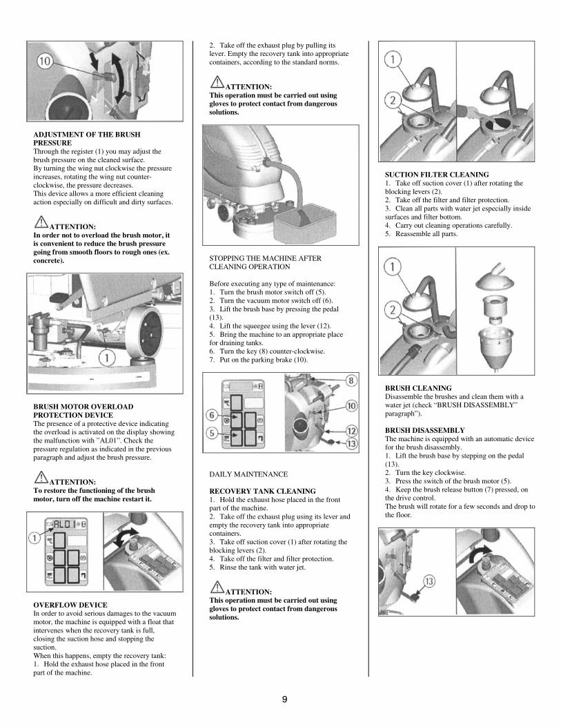
ADJUSTMENT OF THE BRUSHPRESSUREThrough the register (1) you may adjust thebrush pressure on the cleaned surface.By turning the wing nut clockwise the pressureincreases, rotating the wing nut counter-clockwise, the pressure decreases.This device allows a more efficient cleaningaction especially on difficult and dirty surfaces.
ATTENTION:In order not to overload the brush motor, itis convenient to reduce the brush pressuregoing from smooth floors to rough ones (ex.concrete).
BRUSH MOTOR OVERLOADPROTECTION DEVICEThe presence of a protective device indicatingthe overload is activated on the display showingthe malfunction with ”AL01”. Check thepressure regulation as indicated in the previousparagraph and adjust the brush pressure.
ATTENTION:To restore the functioning of the brushmotor, turn off the machine restart it.
OVERFLOW DEVICEIn order to avoid serious damages to the vacuummotor, the machine is equipped with a float thatintervenes when the recovery tank is full,closing the suction hose and stopping thesuction.When this happens, empty the recovery tank:1. Hold the exhaust hose placed in the frontpart of the machine.
2. Take off the exhaust plug by pulling itslever. Empty the recovery tank into appropriatecontainers, according to the standard norms.
ATTENTION:This operation must be carried out usinggloves to protect contact from dangeroussolutions.
STOPPING THE MACHINE AFTERCLEANING OPERATION
Before executing any type of maintenance:1. Turn the brush motor switch off (5).2. Turn the vacuum motor switch off (6).3. Lift the brush base by pressing the pedal(13).4. Lift the squeegee using the lever (12).5. Bring the machine to an appropriate placefor draining tanks.6. Turn the key (8) counter-clockwise.7. Put on the parking brake (10).
DAILY MAINTENANCE
RECOVERY TANK CLEANING1. Hold the exhaust hose placed in the frontpart of the machine.2. Take off the exhaust plug using its lever andempty the recovery tank into appropriatecontainers.3. Take off suction cover (1) after rotating theblocking levers (2).4. Take off the filter and filter protection.5. Rinse the tank with water jet.
ATTENTION:This operation must be carried out usinggloves to protect contact from dangeroussolutions.
SUCTION FILTER CLEANING1. Take off suction cover (1) after rotating theblocking levers (2).2. Take off the filter and filter protection.3. Clean all parts with water jet especially insidesurfaces and filter bottom.4. Carry out cleaning operations carefully.5. Reassemble all parts.
BRUSH CLEANINGDisassemble the brushes and clean them with awater jet (check “BRUSH DISASSEMBLY”paragraph”).
BRUSH DISASSEMBLYThe machine is equipped with an automatic devicefor the brush disassembly.1. Lift the brush base by stepping on the pedal(13).2. Turn the key clockwise.3. Press the switch of the brush motor (5).4. Keep the brush release button (7) pressed, onthe drive control.The brush will rotate for a few seconds and drop tothe floor.
�0
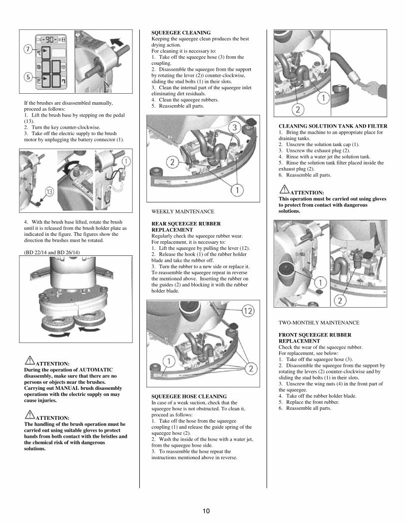
If the brushes are disassembled manually,proceed as follows:1. Lift the brush base by stepping on the pedal(13).2. Turn the key counter-clockwise.3. Take off the electric supply to the brushmotor by unplugging the battery connector (1).
4. With the brush base lifted, rotate the brushuntil it is released from the brush holder plate asindicated in the figure. The figures show thedirection the brushes must be rotated.
(BD 22/14 and BD 26/14)
ATTENTION:During the operation of AUTOMATICdisassembly, make sure that there are nopersons or objects near the brushes.Carrying out MANUAL brush disassemblyoperations with the electric supply on maycause injuries.
ATTENTION:The handling of the brush operation must becarried out using suitable gloves to protecthands from both contact with the bristles andthe chemical risk of with dangeroussolutions.
SQUEEGEE CLEANINGKeeping the squeegee clean produces the bestdrying action.For cleaning it is necessary to:1. Take off the squeegee hose (3) from thecoupling.2. Disassemble the squeegee from the supportby rotating the lever (2)) counter-clockwise,sliding the stud bolts (1) in their slots.3. Clean the internal part of the squeegee inleteliminating dirt residuals.4. Clean the squeegee rubbers.5. Reassemble all parts.
WEEKLY MAINTENANCE
REAR SQUEEGEE RUBBERREPLACEMENTRegularly check the squeegee rubber wear.For replacement, it is necessary to:1. Lift the squeegee by pulling the lever (12).2. Release the hook (1) of the rubber holderblade and take the rubber off.3. Turn the rubber to a new side or replace it.To reassemble the squeegee repeat in reversethe mentioned above. Inserting the rubber onthe guides (2) and blocking it with the rubberholder blade.
SQUEEGEE HOSE CLEANINGIn case of a weak suction, check that thesqueegee hose is not obstructed. To clean it,proceed as follows:1. Take off the hose from the squeegeecoupling (1) and release the guide spring of thesqueegee hose (2).2. Wash the inside of the hose with a water jet,from the squeegee hose side.3. To reassemble the hose repeat theinstructions mentioned above in reverse.
CLEANING SOLUTION TANK AND FILTER1. Bring the machine to an appropriate place fordraining tanks.2. Unscrew the solution tank cap (1).3. Unscrew the exhaust plug (2).4. Rinse with a water jet the solution tank.5. Rinse the solution tank filter placed inside theexhaust plug (2).6. Reassemble all parts.
ATTENTION:This operation must be carried out using glovesto protect from contact with dangeroussolutions.
TWO-MONTHLY MAINTENANCE
FRONT SQUEEGEE RUBBERREPLACEMENTCheck the wear of the squeegee rubber.For replacement, see below:1. Take off the squeegee hose (3).2. Disassemble the squeegee from the support byrotating the levers (2) counter-clockwise and bysliding the stud bolts (1) in their slots.3. Unscrew the wing nuts (4) in the front part ofthe squeegee.4. Take off the rubber holder blade.5. Replace the front rubber.6. Reassemble all parts.
��
SIX-MONTH MAINTENANCE
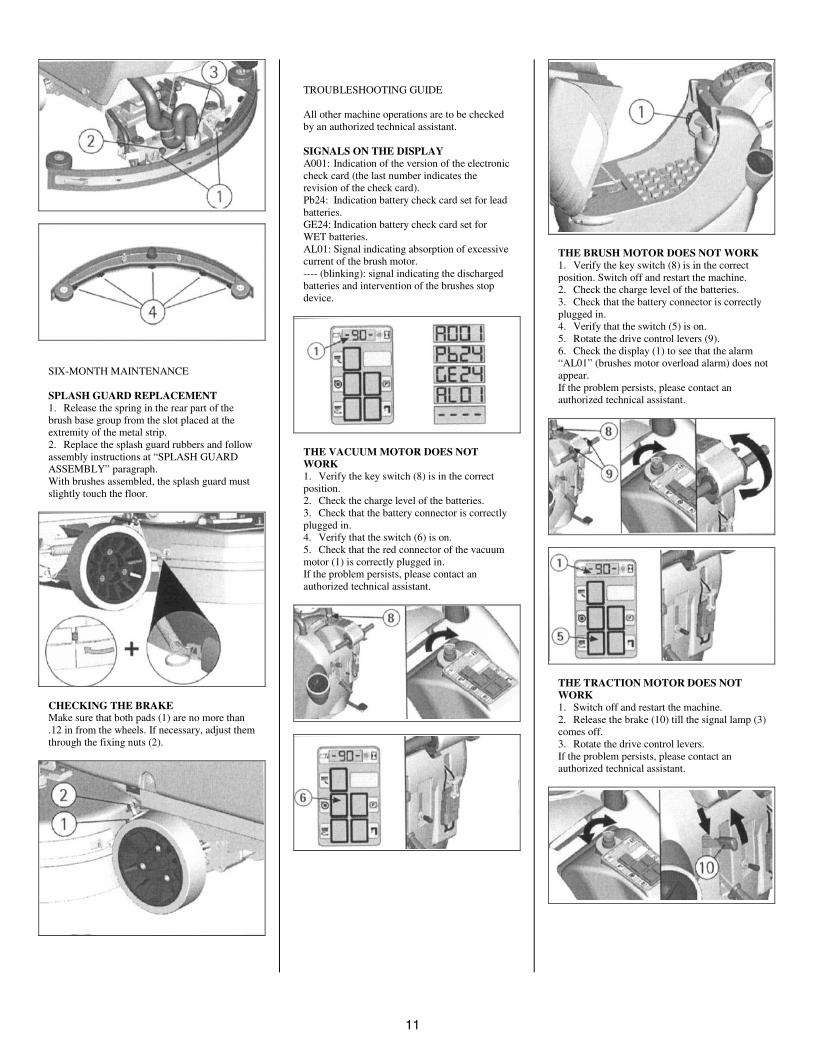
SPLASH GUARD REPLACEMENT1. Release the spring in the rear part of thebrush base group from the slot placed at theextremity of the metal strip.2. Replace the splash guard rubbers and followassembly instructions at “SPLASH GUARDASSEMBLY” paragraph.With brushes assembled, the splash guard mustslightly touch the floor.
CHECKING THE BRAKEMake sure that both pads (1) are no more than.12 in from the wheels. If necessary, adjust themthrough the fixing nuts (2).
TROUBLESHOOTING GUIDE
All other machine operations are to be checkedby an authorized technical assistant.
SIGNALS ON THE DISPLAYA001: Indication of the version of the electroniccheck card (the last number indicates therevision of the check card).Pb24: Indication battery check card set for leadbatteries.GE24: Indication battery check card set forWET batteries.AL01: Signal indicating absorption of excessivecurrent of the brush motor.---- (blinking): signal indicating the dischargedbatteries and intervention of the brushes stopdevice.
THE VACUUM MOTOR DOES NOTWORK1. Verify the key switch (8) is in the correctposition.2. Check the charge level of the batteries.3. Check that the battery connector is correctlyplugged in.4. Verify that the switch (6) is on.5. Check that the red connector of the vacuummotor (1) is correctly plugged in.If the problem persists, please contact anauthorized technical assistant.
THE BRUSH MOTOR DOES NOT WORK1. Verify the key switch (8) is in the correctposition. Switch off and restart the machine.2. Check the charge level of the batteries.3. Check that the battery connector is correctlyplugged in.4. Verify that the switch (5) is on.5. Rotate the drive control levers (9).6. Check the display (1) to see that the alarm“AL01” (brushes motor overload alarm) does notappear.If the problem persists, please contact anauthorized technical assistant.
THE TRACTION MOTOR DOES NOTWORK1. Switch off and restart the machine.2. Release the brake (10) till the signal lamp (3)comes off.3. Rotate the drive control levers.If the problem persists, please contact anauthorized technical assistant.
�4
INSUFFICIENT WATER ON THEBRUSHES1. Check that the solution valve lever (11) isopen.2. Check the level of the liquid in the solutiontank.3. Check that the solution filter (2) is clean.4. The machine is equipped with solenoidvalve, therefore rotate the drive control levers(9).If the problem persists, please contact anauthorized technical assistant.
MACHINE DOES NOT CLEANPROPERLY1. The brushes do not have the suitable bristledimension: contact an authorized technicalassistant.2. The brushes have got worn bristles. Checkthe brushes wear condition and replace them(the brushes have to be replaced when thebristles have reached a height of about .6 in).To replace brushes, see instructions atparagraph “BRUSHES DISASSEMBLY” and“BRUSHES ASSEMBLY”.3. The solution detergent is insufficient: openthe solution valve more.
4. Check that the liquid detergent is in therecommended percentage.5. Increase the brush base pressure (see atparagraph "ADJUSTMENT OF THE BRUSHPRESSURE").Contact an authorized technical assistant foradvice.
SQUEEGEE DOES NOT DRY PROPERLY1. Check that the squeegee rubbers are clean.2. Check the height and the inclination of thesqueegee. (see section “ADJUSTMENT OFTHE SQUEEGEE” in “BEFORE USE”).3. Check that the suction hose is correctlyinserted in the proper seat on the recovery tank.4. Clean the suction filter.5. Replace the rubbers if worn out.6. Check that the vacuum motor switch is on.
EXCESSIVE FOAM PRODUCTIONCheck that low foam detergent has been used.Add small quantities of anti foam liquid into therecovery tank.Please be aware that a bigger quantity of foamis produced when the floor is not dirty. In thiscase please dilute detergent solution.
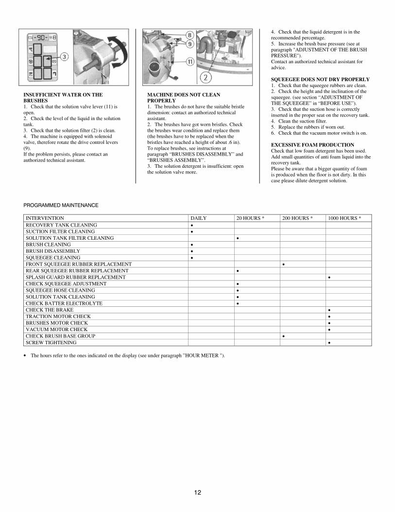
7&/87-(�5#192-9#9)-
INTERVENTION DAILY 20 HOURS * 200 HOURS * 1000 HOURS *RECOVERY TANK CLEANING •
SUCTION FILTER CLEANING •
SOLUTION TANK FILTER CLEANING •
BRUSH CLEANING •
BRUSH DISASSEMBLY •
SQUEEGEE CLEANING •
FRONT SQUEEGEE RUBBER REPLACEMENT •
REAR SQUEEGEE RUBBER REPLACEMENT •
SPLASH GUARD RUBBER REPLACEMENT •
CHECK SQUEEGEE ADJUSTMENT •
SQUEEGEE HOSE CLEANING •
SOLUTION TANK CLEANING •
CHECK BATTER ELECTROLYTE •
CHECK THE BRAKE •
TRACTION MOTOR CHECK •
BRUSHES MOTOR CHECK •
VACUUM MOTOR CHECK •
CHECK BRUSH BASE GROUP •
SCREW TIGHTENING •
• The hours refer to the ones indicated on the display (see under paragraph ”HOUR METER ").
Recommended


![l>lf·· E ·B; -I,:,C-·-1·1V · cat. no.i bd lj.657 bd lj.6]5 bd 4630 bd 4·627 bd 4628 bd 4886 bd 4546 bd 4·545 bd 4544 bd 4542 bd lj,588 bd lj.593 bd 0102 bd 4636 bd 4632 bd](https://img.pdfslide.us/doc/110x75/5f7c69bb7d840d18665ab1e6/llf-e-b-ic-11v-cat-noi-bd-lj657-bd-lj65-bd-4630-bd-4627-bd-4628-bd.jpg)