TOPOLOGY DESIGN AND SCHEDULING IN STDMA
BASED WIRELESS AD HOC NETWORKS
A THESIS
SUBMITTED TO THE DEPARTMENT OF ELECTRICAL AND
ELECTRONICS ENGINEERING
AND THE INSTITUTE OF ENGINEERING AND SCIENCES
OF BILKENT UNIVERSITY
IN PARTIAL FULFILLMENT OF THE REQUIREMENTS
FOR THE DEGREE OF
MASTER OF SCIENCE
By
Sadettin Alp Ergin
September 2003
I certify that I have read this thesis and in my opinion it is fully adequate, in scope and in quality, as a thesis for the degree of Master of Sciences.
Assist. Prof. Dr. Ezhan Karaşan (Supervisor)
I certify that I have read this thesis and in my opinion it is fully adequate, in scope and in quality, as a thesis for the degree of Master of Sciences.
Assist. Prof. Dr. Nail Akar
I certify that I have read this thesis and in my opinion it is fully adequate, in scope and in quality, as a thesis for the degree of Master of Sciences.
Prof. Dr. Hayrettin Köymen
Approved for the Institute of Engineering and Sciences
Prof. Dr. Mehmet Baray Director of Institue of Engineering and Sciences
ii ii
ABSTRACT
TOPOLOGY DESIGN AND SCHEDULING IN STDMA
BASED WIRELESS AD HOC NETWORKS
Sadettin Alp Ergin
M.S. in Electrical and Electronics Engineering
Supervisor: Assist. Prof. Dr. Ezhan Karaşan
September 2003
With current advances in technology, wireless networks are increasing in
popularity. Wireless networks allow users the freedom to travel from one
location to another without interruption of their communication activities. Ad
hoc networks, a subset of wireless networks, allow the formation of a wireless
network without the need for a base station. Since no fixed infrastructure is
involved in the communication, the nodes of ad hoc networks can communicate
with each other or can relay data to other nodes. With this flexibility, wireless ad
hoc networks have the ability to form a network anywhere, at any time, as long
as two or more wireless users are willing to communicate.
Managing ad hoc networks is a significantly more difficult task than
managing wireline networks. The network requirements should be met by
combined efforts of all the mobile nodes themselves. The nodes of ad hoc
networks often operate under severe constraints, such as limited battery power,
variable link quality and limited shared bandwidth. In this study, the topology
design issue in ad hoc wireless networks is investigated. We employ hierarchical
iii iii
routing where the network topology is composed of clusters interconnected via a
root node. Cluster-based topologies are suitable for military services, an
important application area for ad hoc networks. The common power control
technique (COMPOW) is used in this thesis where all nodes transmit at the same
power level. Nodes employ the spatial TDMA (STDMA) scheme in order to
access the channel. An important task is how to produce a minimum STDMA
frame length, and this problem is known to be NP complete. We develop a
heuristic algorithm for generating the minimum STDMA frame length. A new
interference model for ad hoc networks is proposed which utilizes a hypergraph
model. The relationship between the frame length, number of clusters and the
transmit power level are investigated through numerical examples using a 15-
node network.
Keywords: Ad hoc networks, topology design, STDMA, hierarchical routing,
interference hypergraph model.
iv iv
ÖZET
AD HOC KABLOSUZ AĞLARDA TOPOLOJİ
TASARIMI VE ZAMAN ÇİZELGELEMESİ
Sadettin Alp Ergin
Elektrik ve Elektronik Mühendisliği Bölümü Yüksek Lisans
Tez Yöneticisi: Yrd. Doç. Dr. Ezhan Karaşan
Eylül 2003
Teknolojideki son gelişmeler kalosuz ağların popülaritesini arttırdı. Kablosuz
ağlar kullanıcıya bir yerden bir yere giderken kesintisiz komünikasyon
sağlamaktadır. Kablosuz ağların bir alt kümesi olan ad hoc kablosuz ağlar,
herhangi bir baz istasyona gerek duymaksızın bir şebeke kurulmasını sağlar.
Haberleşmede sabit bir yardımcı tesis olmadığı için, ad hoc ağ istasyonları ya
birbirleri ile haberleşir ya da gelen bilgiyi diğer istasyonlara yönlendirirler. Bu
kolaylık sayesinde, ad hoc kablosuz ağların iki veya daha çok istasyon istediği
müddetce her yerde ve her zaman bir ağ oluşturma kabiliyetleri mevcuttur.
Ad hoc ağların idaresi kablolu ağlara nazaran oldukça zor bir görevdir.
Ağ ihtiyaçları bütün istasyonların gayretleri ile karşılanır. Bununla beraber ad
hoc ağ istasyonları sınırlı batarya gücü, değişken link kalitesi ve sınırlı paylaşılan
band genişliği gibi çok kuvvetli kısıtlamalar altında çalışırlar. Bu çalışmada, ad
hoc kablosuz ağlarda topoloji tasarımı problemi araştırıldı. Grupların ana
istasyon üzerinden birbirleri ile bağlantılarını sağladığı topolojide hiyerarşik
v v
yönlendirme kullanıldı. Gruplandırma temelli topolojiler ad hoc ağlar için önemli
bir uygulama alanı olan askeri operasyonlar için çok uygun olmaktadır. Uzaysal
zaman bölümlemeli çoklu erişim metodu istasyonların kanala ulaşma metodu
olarak seçildi. Tezde, bütün istasyonların aynı gönderme güç seviyesini
kulllandığı ortak güç kontrol metodu kullanıldı. Bunlara ilaveten üstün çizgeler
kullanılarak yeni bir girişim modeli sunuldu. Zaman uzunluğu, grup sayısı ve
gönderme güç seviyeleri arasındaki ilişki 15 istasyonluk bir ağ kullanılarak
bulunan sonuçlarla incelendi.
Anahtar Kelimeler: Ad hoc ağları, topoloji tasarımı, uzaysal zaman bölümlemeli
çoklu erişim, hiyerarşik yönlendirme, üstün çizge girişim modeli.
vi vi

ACKNOWLEDGEMENTS
I would like to express my gratitude to my advisor, Dr. Ezhan Karaşan. His
valuable support, encouragement and exceptional guidance throughout my
graduate school years helped me accomplish this work. I also thank him for
leading me into the interesting field of wireless ad hoc networks. I gained a lot of
knowledge and valuable experience while working with him.
I am very thankful to Prof. Dr. Hayrettin Köymen and Dr. Nail Akar for kindly
reviewing my thesis. I would like to thank all faculty member of the department
of electrical and electronics engineering for their distinctive teaching in many
courses. I also wish to specially thank Professor Bülent Özgüler for his
considerable support and encouragement during my graduate study in Bilkent
University.
I am very grateful to Turkish Land Forces for giving the great opportunity to
continue my education in Bilkent University.
It is extremely hard to find words that express my gratitude to my wife Dilek for
her invaluable help over all these years. With her love and dedication she gave
me the extra courage and confidence during my studies.
Throughout the three years I spent in Bilkent I had the chance to meet a lot of
new friends. They made life easier and I wish them all luck in their future plans.
I should also express my special thanks to Mürüvvet Hanım for helps during my
graduate years.
Last, but not the least, I thank my friend Aydoğan Önal for his unique and
perfect friendship.
vii vii
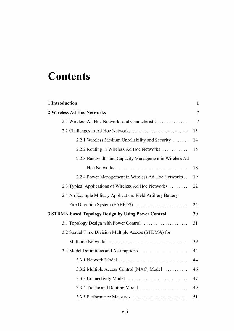
Contents
1 Introduction 1
2 Wireless Ad Hoc Networks 7
2.1 Wireless Ad Hoc Networks and Characteristics . . . . . . . . . . . . 7
2.2 Challenges in Ad Hoc Networks . . . . . . . . . . . . . . . . . . . . . . . . 13
2.2.1 Wireless Medium Unreliability and Security . . . . . . . 14
2.2.2 Routing in Wireless Ad Hoc Networks . . . . . . . . . . . 15
2.2.3 Bandwidth and Capacity Management in Wireless Ad
Hoc Networks . . . . . . . . . . . . . . . . . . . . . . . . . . . . . . . 18
2.2.4 Power Management in Wireless Ad Hoc Networks . . 19
2.3 Typical Applications of Wireless Ad Hoc Networks . . . . . . . . 22
2.4 An Example Military Application: Field Artillery Battery
Fire Direction System (FABFDS) . . . . . . . . . . . . . . . . . . . . . . 24
3 STDMA-based Topology Design by Using Power Control 30
3.1 Topology Design with Power Control . . . . . . . . . . . . . . . . . . . 31
3.2 Spatial Time Division Multiple Access (STDMA) for
Multihop Networks . . . . . . . . . . . . . . . . . . . . . . . . . . . . . . . . . . 39
3.3 Model Definitions and Assumptions . . . . . . . . . . . . . . . . . . . . . 44
3.3.1 Network Model . . . . . . . . . . . . . . . . . . . . . . . . . . . . . . 44
3.3.2 Multiple Access Control (MAC) Model . . . . . . . . . . 46
3.3.3 Connectivity Model . . . . . . . . . . . . . . . . . . . . . . . . . . 47
3.3.4 Traffic and Routing Model . . . . . . . . . . . . . . . . . . . . 49
3.3.5 Performance Measures . . . . . . . . . . . . . . . . . . . . . . . . 51
viii viii
4 Greedy Heuristic Algorithm for Generating the Desired Topology 52
4.1 Interference Hypergraph Model for Ad Hoc Networks . . . . . . 53
4.2 Generating All Maximal Independent Set of Hypergraph . . . . . 56
4.3 Forming Hierarchical Clustered Structure . . . . . . . . . . . . . . . . . 59
4.4 Assigning Time Slots to Selected Links . . . . . . . . . . . . . . . . . . 66
4.5 Numerical Results of Greedy Heuristic . . . . . . . . . . . . . . . . . . . 71
4.6 Distributed Algorithm of Heuristic Solution . . . . . . . . . . . . . . . 77
5 Conclusion 81
ix ix
List of Figures
2.1 Example of infrastructured wireless networks (Cellular networks). . . . . 8
2.2 Example of wireless ad hoc network. . . . . . . . . . . . . . . . . . . . . . . . . . . . 10
2.3 Examples of the two paradigms of wireless networks. . . . . . . . . . . . . . . 11
2.4 Ad hoc networks connected to fixed networks. . . . . . . . . . . . . . . . . . . . . 12
2.5 Dynamic topology of wireless ad hoc networks. . . . . . . . . . . . . . . . . . . . 12
2.6 The effect of node movements on routing algorithm. . . . . . . . . . . . . . . . 16
2.7 The effect of link failures on routing algorithm. . . . . . . . . . . . . . . . . . . . 16
2.8 Power control for energy savings. . . . . . . . . . . . . . . . . . . . . . . . . . . . . . . 19
2.9 Power control effects routing policy. . . . . . . . . . . . . . . . . . . . . . . . . . . . . 21
2.10 A picture of modern battlefield communication. . . . . . . . . . . . . . . . . . . . 25
2.11 Field artillery battery fire direction system. . . . . . . . . . . . . . . . . . . . . . . . 26
3.1 Undesired topology picture. . . . . . . . . . . . . . . . . . . . . . . . . . . . . . . . . . . . 32
3.2 Desired topology picture. . . . . . . . . . . . . . . . . . . . . . . . . . . . . . . . . . . . . . 32
3.3 Common power algorithm (COMPOW) scheme. . . . . . . . . . . . . . . . . . . 33
3.4 Adaptive power per node scheme. . . . . . . . . . . . . . . . . . . . . . . . . . . . . . . 34
3.5 Adaptive power per link scheme. . . . . . . . . . . . . . . . . . . . . . . . . . . . . . . 35
3.6 Examples of mobility models. . . . . . . . . . . . . . . . . . . . . . . . . . . . . . . . . . 37
3.7 Frame (S length slot) used in STDMA. . . . . . . . . . . . . . . . . . . . . . . . . . 41
3.8 Link assignment scheduling scheme. . . . . . . . . . . . . . . . . . . . . . . . . . . . 42
3.9 Node assignment scheduling scheme. . . . . . . . . . . . . . . . . . . . . . . . . . . . 43
3.10 Sample network topology. . . . . . . . . . . . . . . . . . . . . . . . . . . . . . . . . . . . 45
3.11 Connected network topology. . . . . . . . . . . . . . . . . . . . . . . . . . . . . . . . . . 49
3.12 Slot assignment where connected topology is not satisfied. . . . . . . . . . . 50
x x
4.1 Additive interference of links B, C and D on Node-1. . . . . . . . . . . . . . . 54
4.2 Our hypergraph model example. . . . . . . . . . . . . . . . . . . . . . . . . . . . . . . . 55
4.3 Un-balanced traffic load. . . . . . . . . . . . . . . . . . . . . . . . . . . . . . . . . . . . . . 61
4.4 Load balancing over the congested links. . . . . . . . . . . . . . . . . . . . . . . . . 62
4.5 Clustering architecture. . . . . . . . . . . . . . . . . . . . . . . . . . . . . .. . . . . . . . . . 63
4.6 Collection and distribution spanning trees for connected topology. . . . . 67
4.7 First slot assignments for connecting to clusters. . . . . . . . . . . . . . . . . . . 68
4.8 Possible links from reached nodes. . . . . . . . . . . . . . . . . . . . . . . . . . . . . . 70
4.9 The picture of the sample network. . . . . . . . . . . . . . . . . . . . . . . . . . . . . . 71
4.10 Transmit power effect over the frame length. . . . . . . . . . . . . . . . . . . . . . 73
4.14 The effect of cluster numbers over the frame length. . . . . . . . . . . . . . . . 75
4.15 The effects of joint transmit power level and clustering size. . . . . . . . . . 76
xi xi

List of Tables
4.1 Table of link assignment schedule list. . . . . . . . . . . . . . . . . . . . . . . . . . 72
xii xii

To My Wife Dilek Ergin
xiii xiii
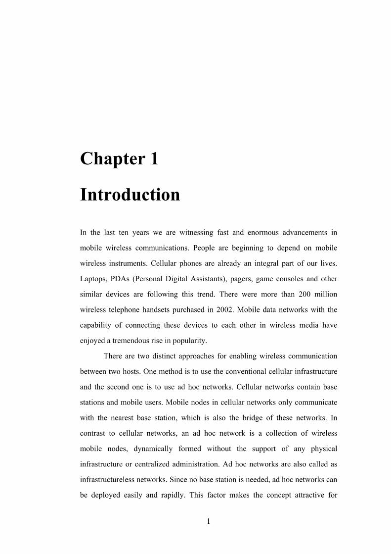
Chapter 1
Introduction In the last ten years we are witnessing fast and enormous advancements in
mobile wireless communications. People are beginning to depend on mobile
wireless instruments. Cellular phones are already an integral part of our lives.
Laptops, PDAs (Personal Digital Assistants), pagers, game consoles and other
similar devices are following this trend. There were more than 200 million
wireless telephone handsets purchased in 2002. Mobile data networks with the
capability of connecting these devices to each other in wireless media have
enjoyed a tremendous rise in popularity.
There are two distinct approaches for enabling wireless communication
between two hosts. One method is to use the conventional cellular infrastructure
and the second one is to use ad hoc networks. Cellular networks contain base
stations and mobile users. Mobile nodes in cellular networks only communicate
with the nearest base station, which is also the bridge of these networks. In
contrast to cellular networks, an ad hoc network is a collection of wireless
mobile nodes, dynamically formed without the support of any physical
infrastructure or centralized administration. Ad hoc networks are also called as
infrastructureless networks. Since no base station is needed, ad hoc networks can
be deployed easily and rapidly. This factor makes the concept attractive for
1 1
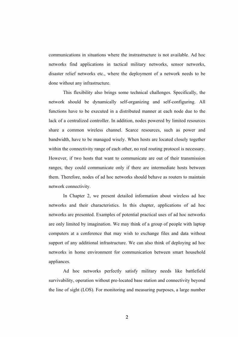
communications in situations where the instrastructure is not available. Ad hoc
networks find applications in tactical military networks, sensor networks,
disaster relief networks etc., where the deployment of a network needs to be
done without any infrastructure.
This flexibility also brings some technical challenges. Specifically, the
network should be dynamically self-organizing and self-configuring. All
functions have to be executed in a distributed manner at each node due to the
lack of a centralized controller. In addition, nodes powered by limited resources
share a common wireless channel. Scarce resources, such as power and
bandwidth, have to be managed wisely. When hosts are located closely together
within the connectivity range of each other, no real routing protocol is necessary.
However, if two hosts that want to communicate are out of their transmission
ranges, they could communicate only if there are intermediate hosts between
them. Therefore, nodes of ad hoc networks should behave as routers to maintain
network connectivity.
In Chapter 2, we present detailed information about wireless ad hoc
networks and their characteristics. In this chapter, applications of ad hoc
networks are presented. Examples of potential practical uses of ad hoc networks
are only limited by imagination. We may think of a group of people with laptop
computers at a conference that may wish to exchange files and data without
support of any additional infrastructure. We can also think of deploying ad hoc
networks in home environment for communication between smart household
appliances.
Ad hoc networks perfectly satisfy military needs like battlefield
survivability, operation without pre-located base station and connectivity beyond
the line of sight (LOS). For monitoring and measuring purposes, a large number
2 2
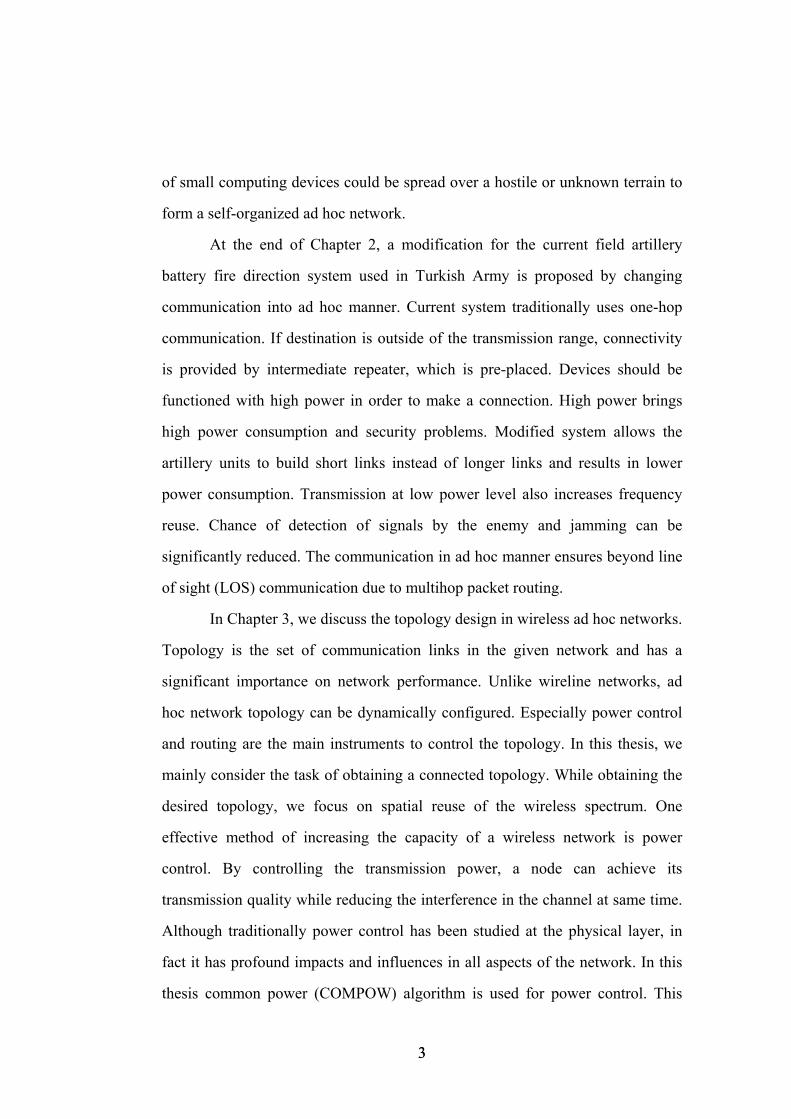
of small computing devices could be spread over a hostile or unknown terrain to
form a self-organized ad hoc network.
At the end of Chapter 2, a modification for the current field artillery
battery fire direction system used in Turkish Army is proposed by changing
communication into ad hoc manner. Current system traditionally uses one-hop
communication. If destination is outside of the transmission range, connectivity
is provided by intermediate repeater, which is pre-placed. Devices should be
functioned with high power in order to make a connection. High power brings
high power consumption and security problems. Modified system allows the
artillery units to build short links instead of longer links and results in lower
power consumption. Transmission at low power level also increases frequency
reuse. Chance of detection of signals by the enemy and jamming can be
significantly reduced. The communication in ad hoc manner ensures beyond line
of sight (LOS) communication due to multihop packet routing.
In Chapter 3, we discuss the topology design in wireless ad hoc networks.
Topology is the set of communication links in the given network and has a
significant importance on network performance. Unlike wireline networks, ad
hoc network topology can be dynamically configured. Especially power control
and routing are the main instruments to control the topology. In this thesis, we
mainly consider the task of obtaining a connected topology. While obtaining the
desired topology, we focus on spatial reuse of the wireless spectrum. One
effective method of increasing the capacity of a wireless network is power
control. By controlling the transmission power, a node can achieve its
transmission quality while reducing the interference in the channel at same time.
Although traditionally power control has been studied at the physical layer, in
fact it has profound impacts and influences in all aspects of the network. In this
thesis common power (COMPOW) algorithm is used for power control. This
3 3
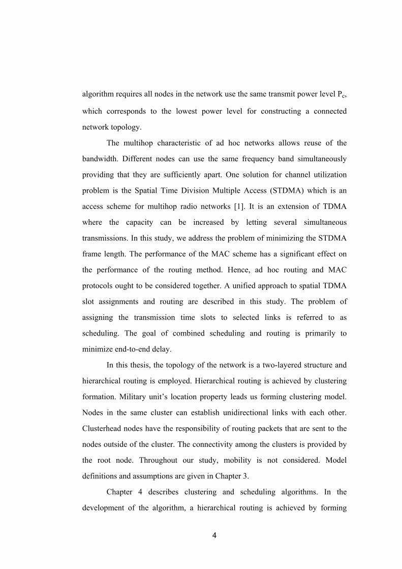
algorithm requires all nodes in the network use the same transmit power level Pc,
which corresponds to the lowest power level for constructing a connected
network topology.
The multihop characteristic of ad hoc networks allows reuse of the
bandwidth. Different nodes can use the same frequency band simultaneously
providing that they are sufficiently apart. One solution for channel utilization
problem is the Spatial Time Division Multiple Access (STDMA) which is an
access scheme for multihop radio networks [1]. It is an extension of TDMA
where the capacity can be increased by letting several simultaneous
transmissions. In this study, we address the problem of minimizing the STDMA
frame length. The performance of the MAC scheme has a significant effect on
the performance of the routing method. Hence, ad hoc routing and MAC
protocols ought to be considered together. A unified approach to spatial TDMA
slot assignments and routing are described in this study. The problem of
assigning the transmission time slots to selected links is referred to as
scheduling. The goal of combined scheduling and routing is primarily to
minimize end-to-end delay.
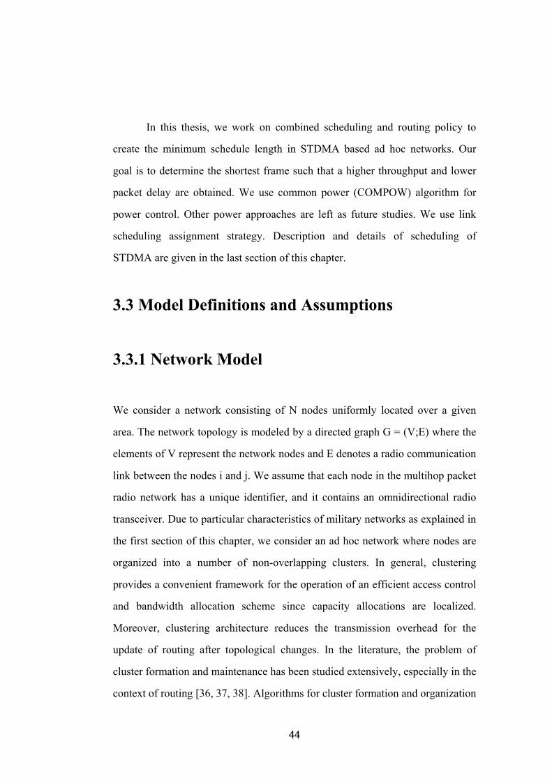
In this thesis, the topology of the network is a two-layered structure and
hierarchical routing is employed. Hierarchical routing is achieved by clustering
formation. Military unit’s location property leads us forming clustering model.
Nodes in the same cluster can establish unidirectional links with each other.
Clusterhead nodes have the responsibility of routing packets that are sent to the
nodes outside of the cluster. The connectivity among the clusters is provided by
the root node. Throughout our study, mobility is not considered. Model
definitions and assumptions are given in Chapter 3.
Chapter 4 describes clustering and scheduling algorithms. In the
development of the algorithm, a hierarchical routing is achieved by forming
4 4
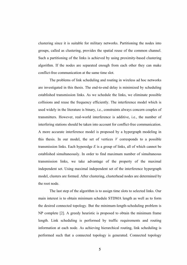
clustering since it is suitable for military networks. Partitioning the nodes into
groups, called as clustering, provides the spatial reuse of the common channel.
Such a partitioning of the links is achieved by using proximity-based clustering
algorithm. If the nodes are separated enough from each other they can make
conflict-free communication at the same time slot.
The problems of link scheduling and routing in wireless ad hoc networks
are investigated in this thesis. The end-to-end delay is minimized by scheduling
established transmission links. As we schedule the links, we eliminate possible
collisions and reuse the frequency efficiently. The interference model which is
used widely in the literature is binary, i.e., constraints always concern couples of
transmitters. However, real-world interference is additive, i.e., the number of
interfering stations should be taken into account for conflict-free communication.
A more accurate interference model is proposed by a hypergraph modeling in
this thesis. In our model, the set of vertices V corresponds to a possible
transmission links. Each hyperedge E is a group of links, all of which cannot be
established simultaneously. In order to find maximum number of simultaneous
transmission links, we take advantage of the property of the maximal
independent set. Using maximal independent set of the interference hypergraph
model, clusters are formed. After clustering, clusterhead nodes are determined by
the root node.
The last step of the algorithm is to assign time slots to selected links. Our
main interest is to obtain minimum schedule STDMA length as well as to form
the desired connected topology. But the minimum-length-scheduling problem is
NP complete [2]. A greedy heuristic is proposed to obtain the minimum frame
length. Link scheduling is performed by traffic requirements and routing
information at each node. As achieving hierarchical routing, link scheduling is
performed such that a connected topology is generated. Connected topology
5 5
implies that each node can reach to all other nodes within an STDMA frame. In
connected topologies, end-to-end delay is limited by the frame length. End-to-
end delay can be minimized by minimizing the frame length. At the end of the
algorithm, connected topology is constructed by minimum STDMA length
frame. A combined scheduling and routing scheme is developed by executing the
same algorithm. The relationship between frame length, number of clusters and
transmit power are investigated through numerical examples using a 15-node
network. At the end of this chapter, a distributed algorithm is given for collecting
all pairs gain and adjacency matrices by the root node. After collecting this
information, scheduling algorithm is executed at the root node, and link
scheduling list is distributed to all other nodes by the root node. Finally, Chapter
5 concludes the thesis.
6 6
Chapter 2
Wireless Ad Hoc Networks
In this chapter, we introduce wireless ad hoc networks. Later features, problems
and applications of wireless ad hoc networks are discussed. At the end of this
chapter, we present field artillery battery fire direction system in ad hoc manner
as a military application.
2.1 Wireless Ad Hoc Networks and Characteristics
With the advances in mobile computing, people are beginning to depend on
mobile wireless instruments. The variety of information services to access via
light, hand-held, cordless devices such as portable computers, mobile phones and
Personal Digital Assistants (PDAs) have changed wireless communication
systems into an indispensable part of any state of the communication networks.
Cellular phones are already an integral part of our life. Laptops, PDAs, pagers,
game consoles and other similar devices are following this trend. Some of the
advantages of mobile wireless networks are
7 7
*Allowed user mobility
*Rapid access to services, regardless of person’s placement
*No need for cabling
*Low costs
Deployment of wireless solutions takes significantly less time compared
to wired solutions. Due to these advantages, such wireless networks could be
more suitable for military and emergency applications, and surveillance of
critical signals and data gathering.
Mobile
Base
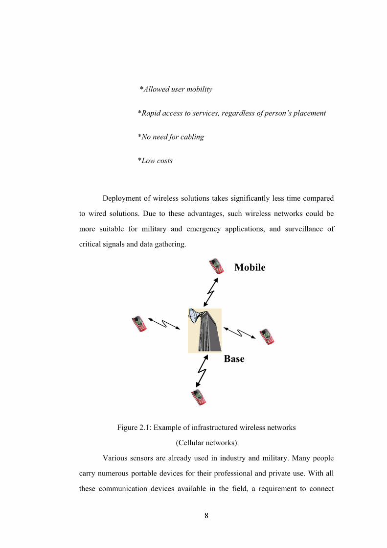
Figure 2.1: Example of infrastructured wireless networks
(Cellular networks).
Various sensors are already used in industry and military. Many people
carry numerous portable devices for their professional and private use. With all
these communication devices available in the field, a requirement to connect
8 8
them easily and efficiently has arisen. There are currently two variations of
mobile wireless networks. Cellular networks are the first example of wireless
services. In these networks, as shown in Figure 2.1, base station and mobile hosts
are grouped into a cellular structure.
The developments in wireless networking have primarily been driven by
the success of the dominant cellular architecture model. In cellular networks, the
base station that is not mobile has the responsibility of maintaining the
communication. A mobile host connects to, and communicates with, the nearest
base station that is within its transmission range. When it goes out of
communication range of one base station, it connects to a new base station and
starts transmitting through it. Base stations are also bridges of these networks.
The second type of mobile wireless network, sometimes referred to as ad
hoc, or peer-to-peer, or multi-hop networks, consists entirely of wireless and
often mobile nodes that may communicate either directly or via multiple hop
paths that require the support of intermediate nodes to achieve connectivity. In
contrast with the cellular architecture, wireless ad hoc networks do not require
centralized access points or pre-existing infrastructure as shown in Figure 2.2.
Absence of an infrastructure is the main difference between ad hoc and cellular
networks. That is the why ad hoc networks are also called the infrastructureless
networks.
9 9
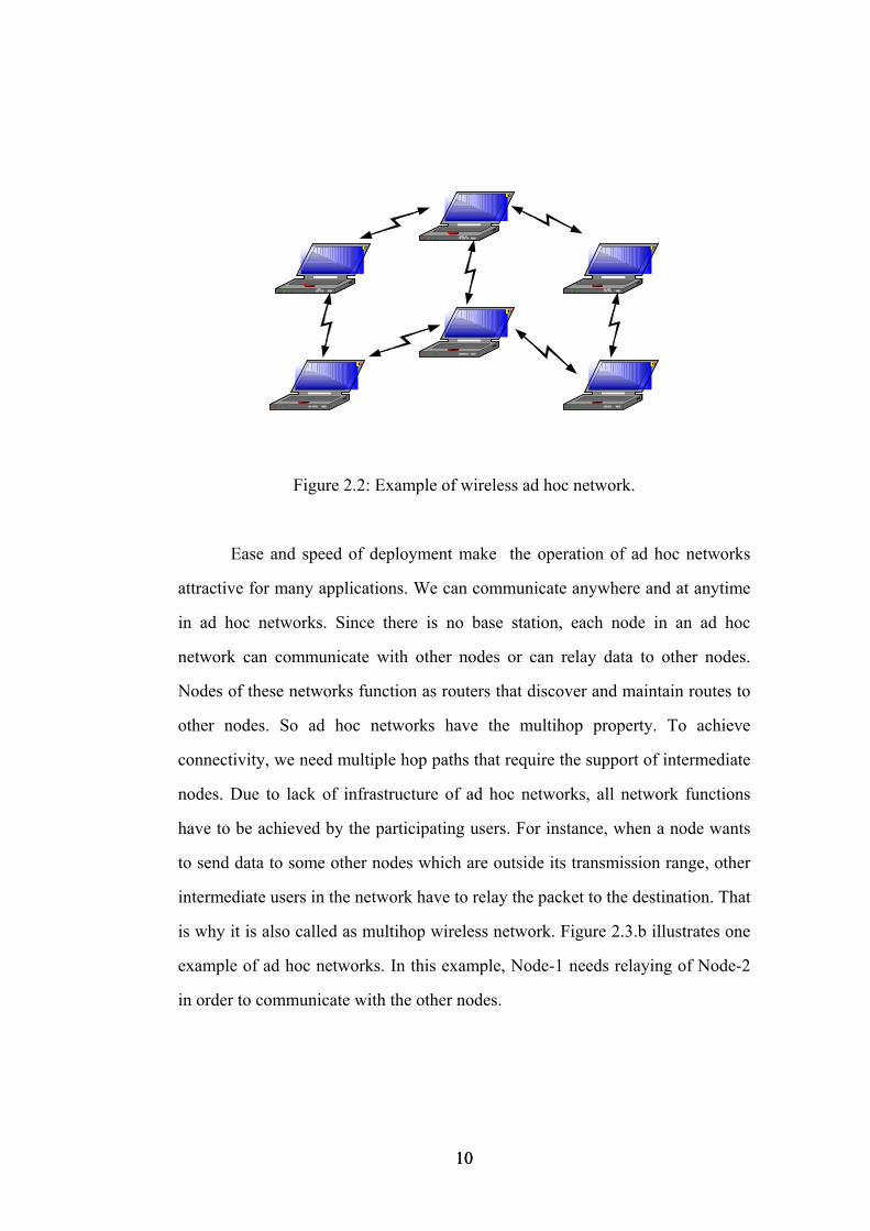
Figure 2.2: Example of wireless ad hoc network.
Ease and speed of deployment make the operation of ad hoc networks
attractive for many applications. We can communicate anywhere and at anytime
in ad hoc networks. Since there is no base station, each node in an ad hoc
network can communicate with other nodes or can relay data to other nodes.
Nodes of these networks function as routers that discover and maintain routes to
other nodes. So ad hoc networks have the multihop property. To achieve
connectivity, we need multiple hop paths that require the support of intermediate
nodes. Due to lack of infrastructure of ad hoc networks, all network functions
have to be achieved by the participating users. For instance, when a node wants
to send data to some other nodes which are outside its transmission range, other
intermediate users in the network have to relay the packet to the destination. That
is why it is also called as multihop wireless network. Figure 2.3.b illustrates one
example of ad hoc networks. In this example, Node-1 needs relaying of Node-2
in order to communicate with the other nodes.
10 10
N2
N1 N3
N4
(a)
BS
N2
N1
N3
N4
(b)
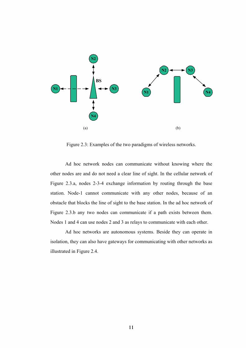
Figure 2.3: Examples of the two paradigms of wireless networks.
Ad hoc network nodes can communicate without knowing where the
other nodes are and do not need a clear line of sight. In the cellular network of
Figure 2.3.a, nodes 2-3-4 exchange information by routing through the base
station. Node-1 cannot communicate with any other nodes, because of an
obstacle that blocks the line of sight to the base station. In the ad hoc network of
Figure 2.3.b any two nodes can communicate if a path exists between them.
Nodes 1 and 4 can use nodes 2 and 3 as relays to communicate with each other.
Ad hoc networks are autonomous systems. Beside they can operate in
isolation, they can also have gateways for communicating with other networks as
illustrated in Figure 2.4.
11 11
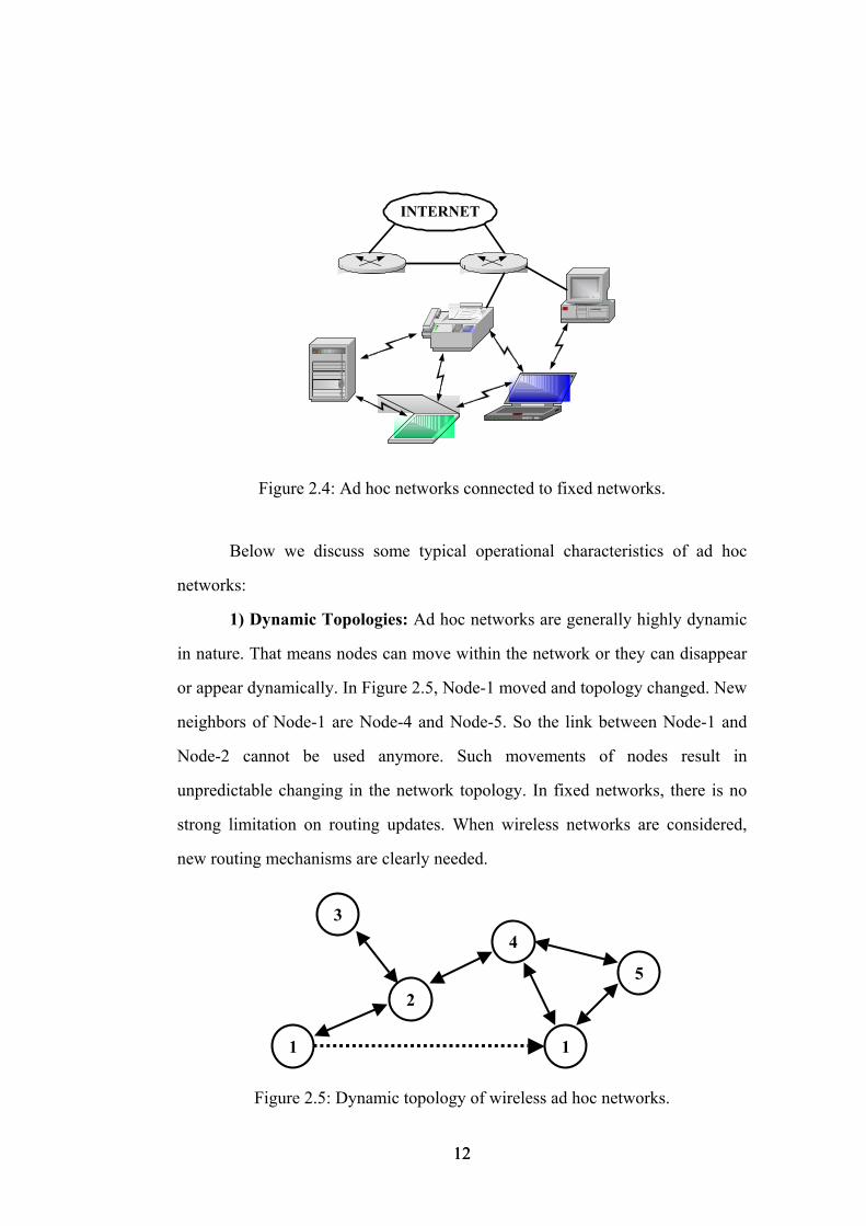
INTERNET
Figure 2.4: Ad hoc networks connected to fixed networks.
Below we discuss some typical operational characteristics of ad hoc
networks:
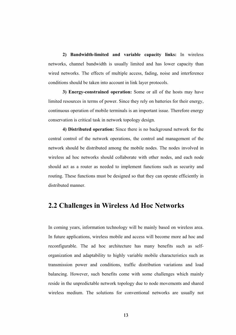
1) Dynamic Topologies: Ad hoc networks are generally highly dynamic
in nature. That means nodes can move within the network or they can disappear
or appear dynamically. In Figure 2.5, Node-1 moved and topology changed. New
neighbors of Node-1 are Node-4 and Node-5. So the link between Node-1 and
Node-2 cannot be used anymore. Such movements of nodes result in
unpredictable changing in the network topology. In fixed networks, there is no
strong limitation on routing updates. When wireless networks are considered,
new routing mechanisms are clearly needed.
1
5
4
2
3
1
Figure 2.5: Dynamic topology of wireless ad hoc networks.
12 12
2) Bandwidth-limited and variable capacity links: In wireless
networks, channel bandwidth is usually limited and has lower capacity than
wired networks. The effects of multiple access, fading, noise and interference
conditions should be taken into account in link layer protocols.
3) Energy-constrained operation: Some or all of the hosts may have
limited resources in terms of power. Since they rely on batteries for their energy,
continuous operation of mobile terminals is an important issue. Therefore energy
conservation is critical task in network topology design.
4) Distributed operation: Since there is no background network for the
central control of the network operations, the control and management of the
network should be distributed among the mobile nodes. The nodes involved in
wireless ad hoc networks should collaborate with other nodes, and each node
should act as a router as needed to implement functions such as security and
routing. These functions must be designed so that they can operate efficiently in
distributed manner.
2.2 Challenges in Wireless Ad Hoc Networks
In coming years, information technology will be mainly based on wireless area.
In future applications, wireless mobile and access will become more ad hoc and
reconfigurable. The ad hoc architecture has many benefits such as self-
organization and adaptability to highly variable mobile characteristics such as
transmission power and conditions, traffic distribution variations and load
balancing. However, such benefits come with some challenges which mainly
reside in the unpredictable network topology due to node movements and shared
wireless medium. The solutions for conventional networks are usually not
13 13
sufficient to provide efficient ad hoc operations. The most important of these
challenges are summarized below.
2.2.1 Wireless Medium Unreliability and Security
Unlike wired networks where an adversary must damage the network wires or
pass through several lines of defense at firewalls and gateways, attacks on a
wireless ad-hoc network can come from all directions and target at any node.
Damages can include leaking secret information, message contamination, and
node impersonation. All these mean that a wireless ad-hoc network will not have
a clear line of defense, and every node must be prepared for encounters with an
adversary directly or indirectly.
Furthermore, the wireless nature of communication and lack of any
security infrastructure raise several reliability problems. Contrary to fixed-cable
networks, wireless ad hoc networks are highly unreliable. Wireless signals are
subject to significant attenuation and distortion, which are generally of random
nature.
Achieving security within ad hoc networking is challenging due to
following reasons [3]:
• Dynamic topologies and membership : A network topology of ad
hoc network is very dynamic as mobility of nodes or membership of nodes is
random and rapid. This emphasizes the need for secure solutions to be dynamic.
• Vulnerable wireless link : Passive/Active link attacks like
eavesdropping, spoofing, denial of service, masquerading, impersonation are
possible.
14 14
• Roaming in dangerous environment : Any malicious node or
misbehaving node can create hostile attack or deprive all other nodes from
providing any service.
Therefore security challenges must be considered when designing a
wireless system. And sufficient levels of security should be provided especially
military and banking applications.
2.2.2 Routing in Wireless Ad Hoc Networks
Since the transmission range of nodes of wireless ad hoc networks is limited, a
routing protocol is needed to enable them to be connected to each other.
Conventional routing protocols are not appropriate for ad hoc mobile networks
due to temporal nature of the wireless links. So the issue of routing packets
between any node pairs becomes a challenging task. Routing is one actively
researched area for mobile ad hoc networks. Moreover, the network topology
changes arbitrarily as the nodes move and information is subject to becoming
obsolete both in time (information may be outdated at some nodes but current at
others) and in space (a node may only know the network topology in its
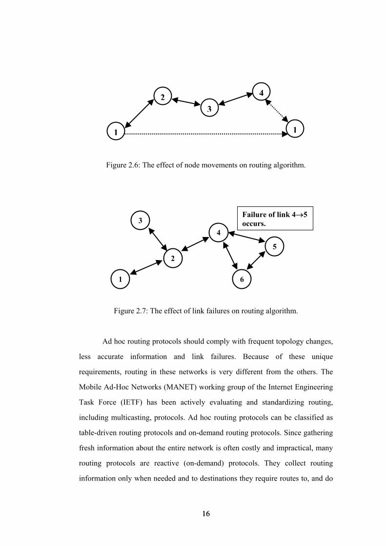
neighborhood and not far away from itself). In Figure 2.6, Node-1 reaches Node-
3 via intermediate Node-2. After changing the location of Node-1, a new path
(Node-1→Node-4→Node3) is established between Node-1 and Node-3. Routing
algorithm should be updated according to this new path. In Figure 2.7, the
current path between Node-5 and Node-2 is Node-5 → Node-4 → Node-2. But
failure of link Node-5 → Node-4 makes the current path obsolete. A new path
needs to be configured, and the routing algorithm computes the new path
Node-5→Node-6→Node-4→Node-2.
15 15
1
4
32
1
Figure 2.6: The effect of node movements on routing algorithm.
Failure of link 4→5 occurs.
6
5
4
2
3
1
Figure 2.7: The effect of link failures on routing algorithm.
Ad hoc routing protocols should comply with frequent topology changes,
less accurate information and link failures. Because of these unique
requirements, routing in these networks is very different from the others. The
Mobile Ad-Hoc Networks (MANET) working group of the Internet Engineering
Task Force (IETF) has been actively evaluating and standardizing routing,
including multicasting, protocols. Ad hoc routing protocols can be classified as
table-driven routing protocols and on-demand routing protocols. Since gathering
fresh information about the entire network is often costly and impractical, many
routing protocols are reactive (on-demand) protocols. They collect routing
information only when needed and to destinations they require routes to, and do
16 16
not maintain unused routes. This way the routing overhead is greatly reduced
compared to pro-active protocols which maintain optimal routes to all
destinations at all time. This is important for a protocol to be adaptive. AODV
[4], DSR [5] and TORA [6] are representatives of on-demand routing protocols
presented at the MANET working group.
Another type of routing protocols is Table-Driven routing protocols also
called as pro-active routing protocols. These protocols require each node to
maintain one or more tables to store routing information, and they respond to
changes in network in order to maintain a consistent network view. Some of
them are Destination-Sequenced Distance-Vector Routing (DSDV) [7],
Clusterhead Gateway Switch Routing (CGSR) [8], and Wireless Routing
Protocol (WRP) [9].
These two types of ad hoc routing protocols have advantages and
drawbacks. In order to provide quality-of-service, routing protocols need not
only to find a route but also to deal with the typical limitations of ad hoc
networks, such as high power consumption, low bandwidth and high error rates.
In the literature, there are some studies that consider efficient minimum energy
routing schemes. In [10], they achieve energy efficient routing by establishing
routes that ensure that all nodes equally deplete their battery power. Subbarao
[11] conducts an initial investigation of energy routing and develops a minimum
power routing scheme using table-driven protocol approach. Singh et al. [12]
introduce power aware cost metrics for routes and design routing policies that
minimize energy consumption.
17 17
2.2.3 Bandwidth and Capacity Management in
Wireless Ad Hoc Networks
Bandwidth-guaranteed service in ad hoc networks is a challenging task due to
several factors such as the absence of central control, the dynamic network
topology, the hidden terminal problem and the multihop routing property. In
addition to these factors, communication is node-based because of the broadcast
nature of the wireless medium. Every transmission by a node can be received by
other nodes that are located within its transmission range. Mobile nodes of the
network share the wireless channel for communication. This causes situations
where two or more stations may want to use the same shared medium at the same
time. Such conflicts result in garbling and eventual loss of data due to collisions.
Therefore, nodes must negotiate with each other to manage the bandwidth.
Nodes require efficient medium access mechanism to schedule their transmission
so that the goals of minimizing interference and efficient utilization of the
bandwidth are satisfied.
Medium access control protocols define rules for orderly access to the
shared medium and play a crucial role in the efficient and fair sharing of scarce
wireless bandwidth. Designing of wireless MAC protocols is the another heavily
researched area for mobile ad hoc networks. Moreover, routing and power
control schemes can also increase the capacity of wireless network. Quality of
Service (QoS) routing requires not only to find a route connecting the source to
the destination, but the route can satisfy the end-to-end QoS requirement, often
given in terms of bandwidth and delay.
18 18
2.2.4 Power Management in Wireless Ad Hoc
Networks
Ad hoc network is a collection of mobile nodes which are generally battery
driven devices. Due to infrastructureless operation, nodes of ad hoc networks
must relay the data to maintain connectivity. This results in extra energy
consumption in the nodes. Therefore power is one of the critical resources, and it
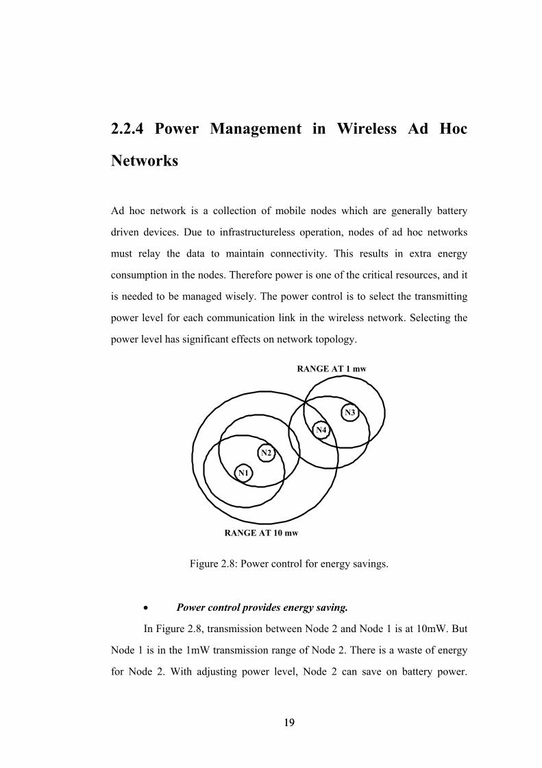
is needed to be managed wisely. The power control is to select the transmitting
power level for each communication link in the wireless network. Selecting the
power level has significant effects on network topology.
RANGE AT 10 mw
RANGE AT 1 mw
N1
N2
N4
N3
Figure 2.8: Power control for energy savings.
• Power control provides energy saving.
In Figure 2.8, transmission between Node 2 and Node 1 is at 10mW. But
Node 1 is in the 1mW transmission range of Node 2. There is a waste of energy
for Node 2. With adjusting power level, Node 2 can save on battery power.
19 19
When all other nodes are considered, choosing convenient power level can
extend network life. Thus energy conservation is a key requirement in the design
of ad hoc networks. Especially in sensor networks with power-aware design, the
node’s energy consumption displays a graceful scalability in energy consumption
at all levels of the system, including the signal processing algorithms, operating
system, and even the integrated circuits themselves. Sensor systems must utilize
the minimal possible energy while operating over a wide range of operating
scenarios. Throughout its lifetime, a node may be called upon to be a data
gatherer, a signal processor, and a relay station. Its lifetime, however, must be on
the order of months to years, since battery replacement for thousands of nodes is
not an option.
• Power control extends capacity of the network.
Simultaneous transmissions cause interference with other nodes.
Bandwidth re-use is desired goal of the wireless network designer. Power control
helps dealing with long term fading effects and interference. When power level
is managed, a transmitter will use the optimal power level that is required to
communicate. Optimal power level results in minimizing interference to other
nodes in the vicinity. In Figure 2.8, Node-3 wants to send data to Node-4 at
1mW. This communication can be established successfully provided that the
transmission between Node-2 and Node-1 is established at 1mW. Otherwise,
using 10mW does not allow communications over both links due to interference
by Node-2 to Node-4. Therefore, power control can enhance the network
capacity.
Power control can be managed in several layers. In the physical layer,
power control impacts the link quality. Ongoing transmission link can be broken
for a while unless power control is not used. However, power control also has
20 20
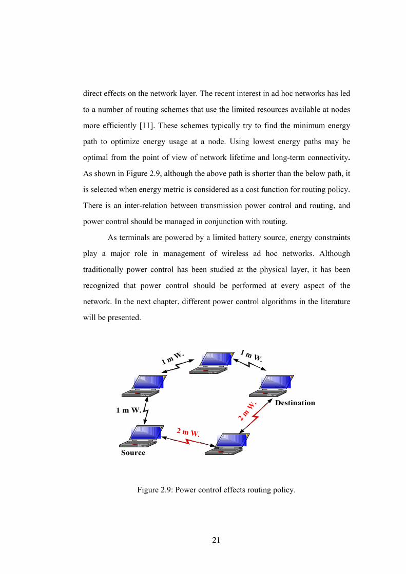
direct effects on the network layer. The recent interest in ad hoc networks has led
to a number of routing schemes that use the limited resources available at nodes
more efficiently [11]. These schemes typically try to find the minimum energy
path to optimize energy usage at a node. Using lowest energy paths may be
optimal from the point of view of network lifetime and long-term connectivity.
As shown in Figure 2.9, although the above path is shorter than the below path, it
is selected when energy metric is considered as a cost function for routing policy.
There is an inter-relation between transmission power control and routing, and
power control should be managed in conjunction with routing.
As terminals are powered by a limited battery source, energy constraints
play a major role in management of wireless ad hoc networks. Although
traditionally power control has been studied at the physical layer, it has been
recognized that power control should be performed at every aspect of the
network. In the next chapter, different power control algorithms in the literature
will be presented.
Source
1 m W. 1 m W.
Destination1 m W.
2 m W
.
2 m W.
Figure 2.9: Power control effects routing policy.
21 21
2.3 Typical Applications of Wireless Ad Hoc
Networks
With the current technology and increasing popularity of notebook computers
and hand-held devices, interest of people in ad hoc networks has greatly peaked.
As stated in the previous section, wireless communication systems have
advantages compared to wireline systems. The most important ones of these
advantages are mobility and cost savings. Mobility lifts the requirement for a
fixed point of connection to the network. Users are able to move while using
their appliances. Wireless networks are also beneficial in reducing network costs.
Therefore, ad hoc networks have been the focus of many recent research and
development efforts. Recent advances in technology allow us to form small ad
hoc networks on campuses, during conferences, and even in our own homes.
They are good for applications in home networks where devices can
communicate directly to exchange information, such as image, alarms, and
configuration updates.
Furthermore, the feature for easily deployable ad hoc networks in rescue
missions and in situations located in rough terrain are becoming extremely
common. Applications of ad-hoc networks range from military tactical
operations to civil rapid deployment such as emergency search-and-rescue
missions, data collection/sensor networks, and instantaneous classroom/meeting
room applications. It is clear that decentralized and self-organized network
structure is an operative advantage or even a necessity for military applications.
Many projects in ad hoc networks have been mainly considered for military
applications. Many countries in all over the world have been focusing on
providing their soldiers with up-to-date technology for wireless communication,
22 22
navigation and information interchange. Major motivation for wireless ad hoc
networks is the military requirement for battlefield survivability. To survive
under battlefield conditions, warfighters and their mobile platforms must be able
to move about freely without any of the restrictions. Therefore, for battlefield
survivability we need mobile wireless communication systems, which are
coordinated in a distributed manner. Soldiers who need to communicate with
each other are deployed over an unfamiliar terrain where no fixed network
infrastructure exists or has failed. The lack of centralized control stations, a main
feature of ad hoc networks, ensure avoiding single points of failure. Here are the
some examples of military applications.
• Infantry and Tank unit collaborations
• Special forces operations
• Sensor networks
• Reconnaissance operations
• Search and Rescue operations
• Unexpected attack in enemy terrain
• Deep valley and mountain operations
• Guard unit in defense
Since ad hoc networks can self-configure and self-organize, they are an
optimal solution for many networking applications. Sensor networks, which
consist of a large amount of disposable sensors, are scattered to collect
background data in the events like earthquakes, nuclear disasters, airplane
disasters, etc. The sensors coordinate to establish a communications network and
then send the data back to the master-site for more intensive analysis. We are
familiar with the communication problems due to breaking down the base
stations especially in earthquakes. Ad hoc networks are the exact solution to deal
with these communication problems. Examples include rescue operations in
23 23
remote areas, or when local coverage must be deployed quickly at a remote
construction site.
In the commercial sector, as the capacity of mobile computing increases,
the need for networking is also expected to rise. Ad hoc networks could serve as
wireless public access in urban areas, with fast deployment and extended
coverage. In office Local Area Networks (LAN), different office equipments
(intelligent devices like PCs, notebooks, mobile phones, PDAs etc.) that want to
communicate with each other can form a temporary network without cabling.
When laptop users go outside their office environment, the need for collaborative
computing is very important. With the presence of ad hoc structure, one can
collaborate and share information via a network that updates instantly to meet the
requirements of business organization. The Bluetooth system is the most
promising technology in the context of personal area networks. The Bluetooth
short-range radio device is expected to cost less than $5 within three years and to
be incorporated into millions of wireless communications devices. Therefore,
wireless data communications devices will connect many of intelligent machines
when some technological problems are solved.
2.4 An Example Military Application: Field
Artillery Battery Fire Direction System (FABFDS)
Wireless networking technology will play a key role in future battlefield
communications. Like many armies, Turkish Armed Forces have a great effort to
introduce a new war fighting capability. The key to this capability is
communications technology that requires a minimal amount of fixed
infrastructure; delivers secure voice, video and data in real time at broadband
24 24
data rates; is small and highly portable and is inexpensive enough to be standard
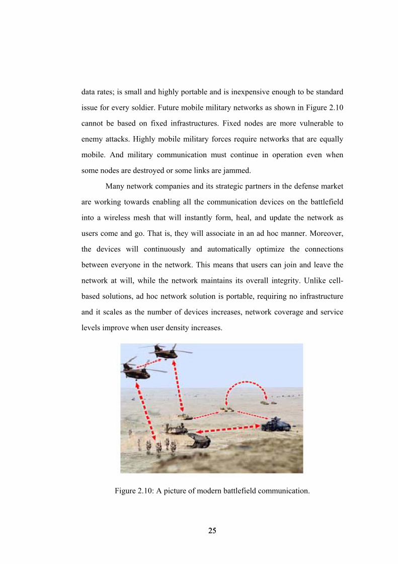
issue for every soldier. Future mobile military networks as shown in Figure 2.10
cannot be based on fixed infrastructures. Fixed nodes are more vulnerable to
enemy attacks. Highly mobile military forces require networks that are equally
mobile. And military communication must continue in operation even when
some nodes are destroyed or some links are jammed.
Many network companies and its strategic partners in the defense market
are working towards enabling all the communication devices on the battlefield
into a wireless mesh that will instantly form, heal, and update the network as
users come and go. That is, they will associate in an ad hoc manner. Moreover,
the devices will continuously and automatically optimize the connections
between everyone in the network. This means that users can join and leave the
network at will, while the network maintains its overall integrity. Unlike cell-
based solutions, ad hoc network solution is portable, requiring no infrastructure
and it scales as the number of devices increases, network coverage and service
levels improve when user density increases.
Figure 2.10: A picture of modern battlefield communication.
25 25
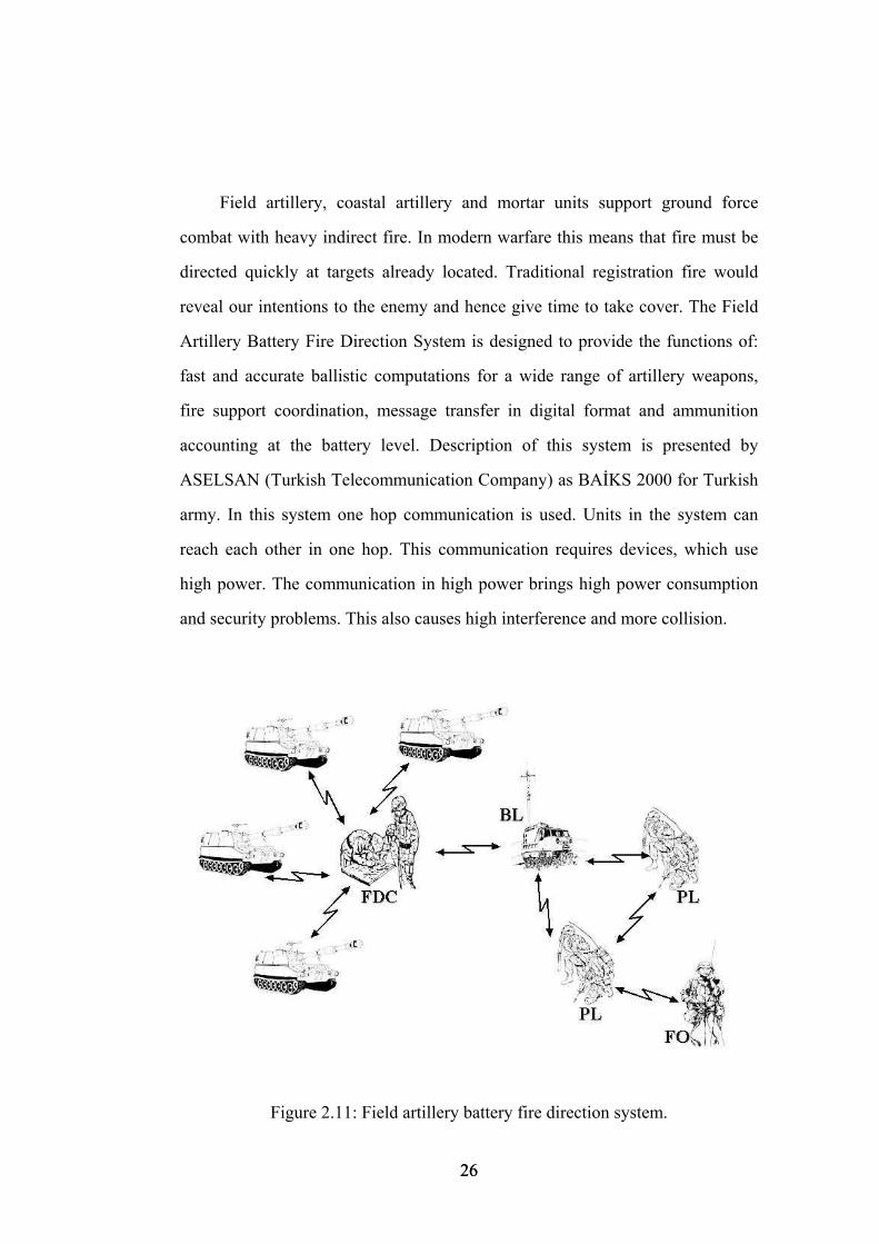
Field artillery, coastal artillery and mortar units support ground force
combat with heavy indirect fire. In modern warfare this means that fire must be
directed quickly at targets already located. Traditional registration fire would
reveal our intentions to the enemy and hence give time to take cover. The Field
Artillery Battery Fire Direction System is designed to provide the functions of:
fast and accurate ballistic computations for a wide range of artillery weapons,
fire support coordination, message transfer in digital format and ammunition
accounting at the battery level. Description of this system is presented by
ASELSAN (Turkish Telecommunication Company) as BAİKS 2000 for Turkish
army. In this system one hop communication is used. Units in the system can
reach each other in one hop. This communication requires devices, which use
high power. The communication in high power brings high power consumption
and security problems. This also causes high interference and more collision.
Figure 2.11: Field artillery battery fire direction system.
26 26
Instead, a system based on ad hoc communication can be built. The
system consists of a battery fire control computer, a communications control
unit, forward observer’s target acquisition device and fire support officer's digital
message device and gun display units. The system units are linked by digital
communications using tactical radios with ad hoc operation capability as shown
in Figure 2.11. The system can also be linked to a tactical fire control system.
Digital message encryption as well as automatic acknowledgement, error
detection and correction capabilities provide safe and reliable communications in
battlefield environment.
In recent years, the methods used by forward observers to determine even
distant targets have improved considerably. The coordinates of the observation
post and the direction of the target can be determined much more accurately.
When laser technology is used, the distance to targets can be determined to the
accuracy of a few meters. Target acquisition devices represent the latest
development, having observation optics, a program to determine your own
location, direction and distance measurement and the calculation of target
coordinates all in the same device. This device also includes ad hoc capable radio
and externally display unit for keeping digital map data and forming needed
messages. Forward observer equipped with this target acquisition, after finding
self-location, points his location in digital map on the display unit and send this
data to platoon leader and fire direction center. This data is to be sent by above
network units in ad hoc manner. Using the same procedure other messages e.g.
fire mission message, can be sent to related units.
The battery fire control computer receives target information and calls for
fire in digital format either from the forward observers or from the battalion
computer. The battery computer computes the firing data for each gun (up to 8
guns) and transfers the firing commands to the gun display units. The battery fire
27 27

control computer and the communication control unit can be mounted in a
vehicle or dismounted in a stationary command post.
Company Fire Support Officer’s Computer (FSOC) provides the
Company Fire Support Team Headquarters with the capabilities for fire support
planning, coordination and execution in a digitally automated environment, as
well as data communications with the other fire support elements.
Gun Commander’s Digital Message Unit (GCDMU) enables gun
commander to digitally communicate with the platoon leader and the
battery/platoon Fire Direction Center. It receives and displays firing data and
sends firing data (azimuth, elevation and fuze setting) digitally to automatic gun
laying, automatic loader and automatic fuze setting systems. It also receives gun
position and pointing data directly from on-board navigation/positioning systems
and sends it to the fire direction center.
The digital message devices and the gun display units are easy-to-use
lightweight handheld units. These devices differ only in their custom keyboards
and software thus leading to savings in logistics and maintenance. The handheld
message units are powered by internal rechargeable batteries.
In ad hoc structured system, transmit power can be reduced significantly.
Instead of establishing longer communication links, by using power control we
can build short links to communicate. For example in Figure 2.11, Forward
Observer sends a fire mission message to Fire Direction Center. This message is
sent to the destination by assisting platoon and battalion leader instead direct link
between Forward Observer and Fire Direction Center. While this communication
is occurring, Fire Direction Center can also receive gun location information
from any of gun commander. All messages can be exchanged at low power
levels by routing via intermediate nodes. This results in many advantages. With
low power devices, we extend our network life, which is very important in
28 28
battlefield. Transmission at low power levels increases spectrum reuse
possibility. Low power level also results in security. Chance of detection of
signals by the enemy can be significantly reduced. Because of multihop packet
routing communication beyond line of sight (LOS) is possible at high
frequencies. The units, which are not within LOS of each other, can easily
exchange messages in ad hoc networks. Moreover, efficient routing algorithms
provide us reusing the frequency and more bandwidth to communicate.
So far, ad hoc networks are discussed with characteristics and challenges.
In the next chapter, topology design issue will be discussed. Power control and
routing schemes need to be considered carefully in order to achieve an optimal
topology. Combined Medium Access Control (MAC) scheme and routing
algorithm will be described for obtaining the desired topology.
29 29
Chapter 3
STDMA-based Topology Design by Using Power Control
In this chapter, we discuss the topology design in wireless ad hoc networks. The
topology of an ad hoc network has a significant impact on its performance. There
are two approaches to topology management in ad hoc networks: topology
control using power control and hierarchical topology organization. We use both
of them in order to have better performance. Power control impacts and
influences many aspects of the network. We discuss types of power control
algorithms in this chapter. In ad hoc networks, the communication channel is
shared among independent stations. MAC mechanisms regulate the access to the
shared channel for maximum channel utilization. We also discuss MAC
protocols in the literature. Especially we focus on Spatial Reuse TDMA
(STDMA) which is an extension of TDMA where the capacity is increased by
letting several radio terminals share the same time slot without any collision. At
the end of this chapter, we give model definitions, assumptions and performance
30 30
measures. Scheduling and routing based on STDMA is also presented in this
chapter.
3.1 Topology Design with Power Control
The topology of a multihop wireless network is the set of communication links
between node pairs used explicitly or implicitly by a routing mechanism [13].
Unlike wireline networks, ad hoc wireless network topology can be controlled. It
is a challenging problem and popular research area of ad hoc networks.
Topology information needs to be considered by network manager. It helps the
manager to monitor topology control decisions within the network such as
connectivity, transmission power and channel bandwidth. Network topology
describes the connectivity and reachability map of the network. In this study, we
are mainly concerned with the task of obtaining a connected topology for
communication. We use delay, network connectivity, load balancing, and power
consumption and frequency reuse as performance metrics in order to evaluate
wireless network topology. Desired topology must ensure good performance
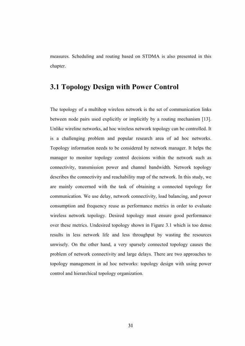
over these metrics. Undesired topology shown in Figure 3.1 which is too dense
results in less network life and less throughput by wasting the resources
unwisely. On the other hand, a very sparsely connected topology causes the
problem of network connectivity and large delays. There are two approaches to
topology management in ad hoc networks: topology design with using power
control and hierarchical topology organization.
31 31
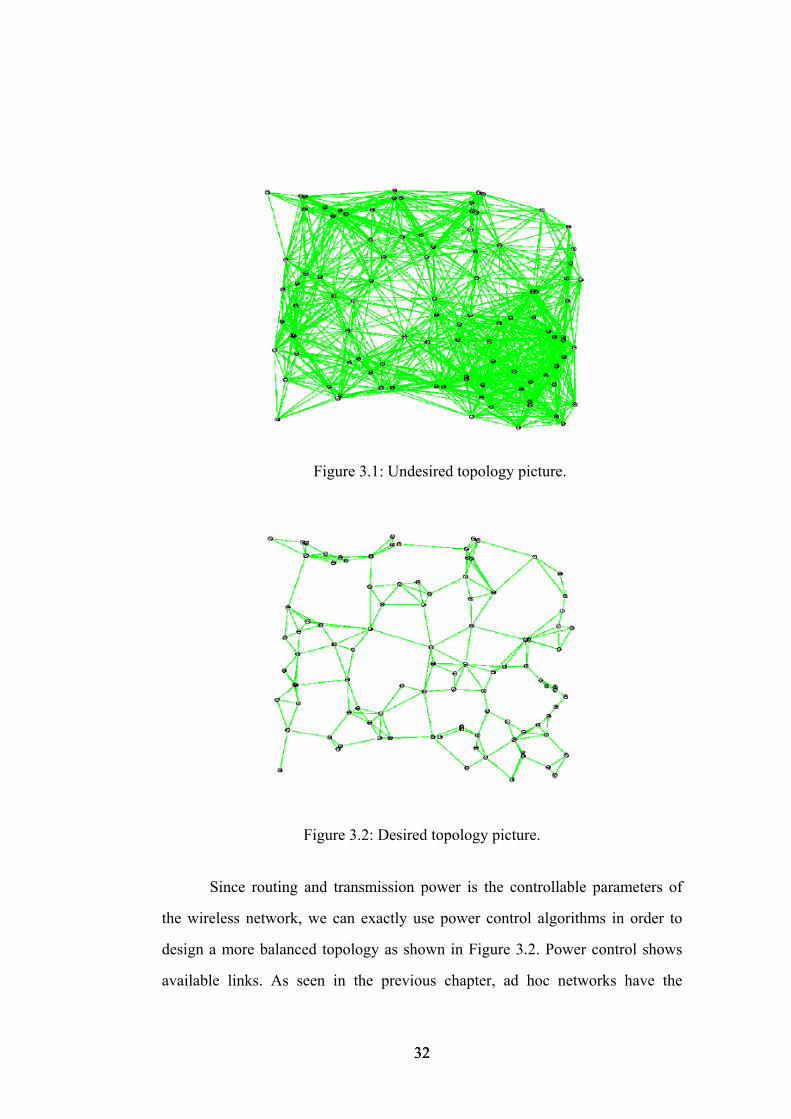
Figure 3.1: Undesired topology picture.
Figure 3.2: Desired topology picture.
Since routing and transmission power is the controllable parameters of
the wireless network, we can exactly use power control algorithms in order to
design a more balanced topology as shown in Figure 3.2. Power control shows
available links. As seen in the previous chapter, ad hoc networks have the
32 32
advantage of saving energy. Throughput and interference are highly related in
wireless networks. By power control we can obtain more spatial reuse and higher
capacity of the network that are the goals of network designer. Without power
control, simultaneous transmission links can not be established due to
interferences.
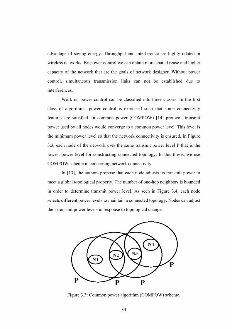
Work on power control can be classified into three classes. In the first
class of algorithms, power control is exercised such that some connectivity
features are satisfied. In common power (COMPOW) [14] protocol, transmit
power used by all nodes would converge to a common power level. This level is
the minimum power level so that the network connectivity is ensured. In Figure
3.3, each node of the network uses the same transmit power level P that is the
lowest power level for constructing connected topology. In this thesis, we use
COMPOW scheme in concerning network connectivity.
In [13], the authors propose that each node adjusts its transmit power to
meet a global topological property. The number of one-hop neighbors is bounded
in order to determine transmit power level. As seen in Figure 3.4, each node
selects different power levels to maintain a connected topology. Nodes can adjust
their transmit power levels in response to topological changes.
Figure 3.3: Common power algorithm (COMPOW) scheme.
33 33
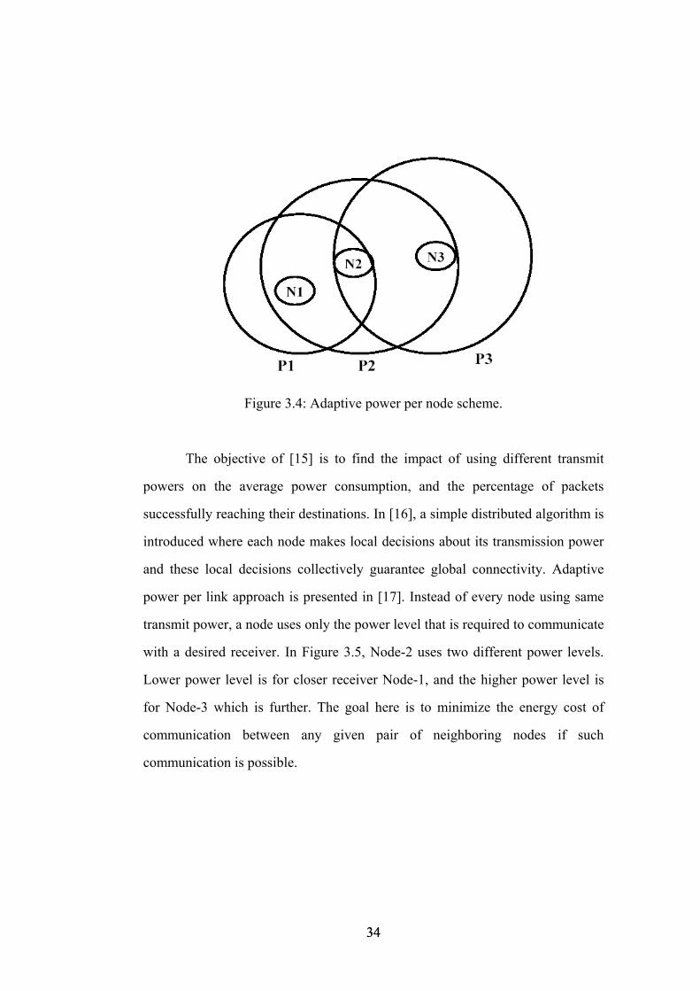
Figure 3.4: Adaptive power per node scheme.
The objective of [15] is to find the impact of using different transmit
powers on the average power consumption, and the percentage of packets
successfully reaching their destinations. In [16], a simple distributed algorithm is
introduced where each node makes local decisions about its transmission power
and these local decisions collectively guarantee global connectivity. Adaptive
power per link approach is presented in [17]. Instead of every node using same
transmit power, a node uses only the power level that is required to communicate
with a desired receiver. In Figure 3.5, Node-2 uses two different power levels.
Lower power level is for closer receiver Node-1, and the higher power level is
for Node-3 which is further. The goal here is to minimize the energy cost of
communication between any given pair of neighboring nodes if such
communication is possible.
34 34
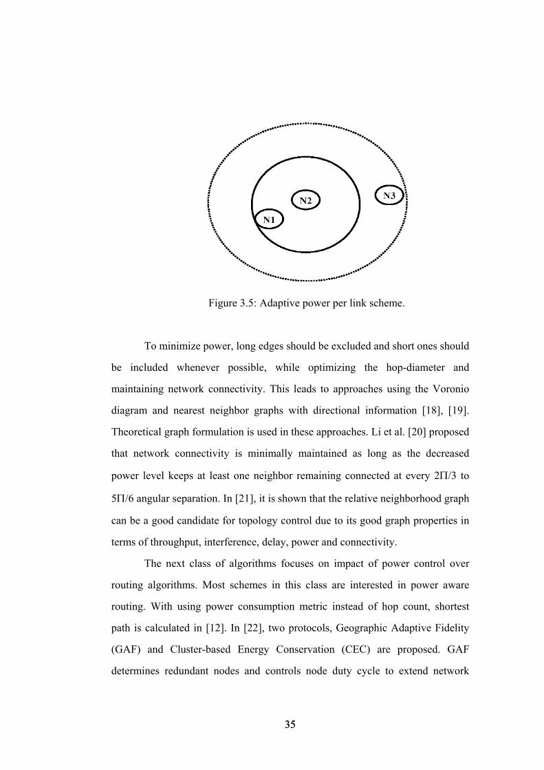
Figure 3.5: Adaptive power per link scheme.
To minimize power, long edges should be excluded and short ones should
be included whenever possible, while optimizing the hop-diameter and
maintaining network connectivity. This leads to approaches using the Voronio
diagram and nearest neighbor graphs with directional information [18], [19].
Theoretical graph formulation is used in these approaches. Li et al. [20] proposed
that network connectivity is minimally maintained as long as the decreased
power level keeps at least one neighbor remaining connected at every 2Π/3 to
5Π/6 angular separation. In [21], it is shown that the relative neighborhood graph
can be a good candidate for topology control due to its good graph properties in
terms of throughput, interference, delay, power and connectivity.
The next class of algorithms focuses on impact of power control over
routing algorithms. Most schemes in this class are interested in power aware
routing. With using power consumption metric instead of hop count, shortest
path is calculated in [12]. In [22], two protocols, Geographic Adaptive Fidelity
(GAF) and Cluster-based Energy Conservation (CEC) are proposed. GAF
determines redundant nodes and controls node duty cycle to extend network
35 35
operational lifetime while maintaining network connectivity, independent of the
involvement of ad hoc routing protocols. GAF can substantially conserve energy
(40% to 60% less energy than an unmodified ad hoc routing protocol), allowing
network operational lifetime to increase in proportion to node density. CEC
eliminates the dependency of GAF on global location information and its
assumption about radio range. CEC measures local connectivity with low
overhead and is thus able to dynamically adapt to a changing network. The other
examples of this class are presented in [11], [23] and [24]. In this thesis, power
aware routing is not considered.
The third class of algorithms points at modifying the MAC layer. In [25],
the PCMA power controlled medium access protocol is introduced within the
collision-avoidance multiple access frameworks. They have demonstrated that
PCMA allows for a greater number of simultaneous senders than 802.11 by
adapting the transmission ranges to be the minimum value required satisfying
successful reception at the intended destination. In [26], a Power Control MAC
protocol (PCM), which periodically increases the transmit power during data
transmission is proposed. In [27], sensor-MAC (S-MAC), a new MAC protocol
which reduces energy consumption is presented. S-MAC achieves good
scalability and collision avoidance by utilizing a combined scheduling and
contention scheme. The other class of MAC protocols is based on reservation
and scheduling, for example TDMA-based protocol. In [28], they present a novel
approach for an energy-aware management for sensor networks. A gateway
node, which is a network manager, monitors latency throughout the cluster and
energy usage at every sensor node. The gateway configures the topology to
extend the network life. They also present new techniques for slot assignment. In
this thesis, we work on Spatial TDMA (STDMA) which is an extension of
TDMA (Time Division Multiple Access). We want to minimize end-to-end delay
36 36
by scheduling established transmission links. As we schedule the links, we
eliminate the possible collisions and reuse the frequency efficiently. The details
of STDMA are presented in the next section.
So far, the relation between power control and topology management is
discussed. When we focus on military applications, network topology also
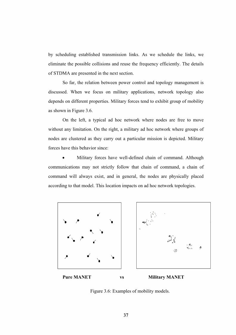
depends on different properties. Military forces tend to exhibit group of mobility
as shown in Figure 3.6.
On the left, a typical ad hoc network where nodes are free to move
without any limitation. On the right, a military ad hoc network where groups of
nodes are clustered as they carry out a particular mission is depicted. Military
forces have this behavior since:
• Military forces have well-defined chain of command. Although
communications may not strictly follow that chain of command, a chain of
command will always exist, and in general, the nodes are physically placed
according to that model. This location impacts on ad hoc network topologies.
Pure MANET vs Military MANET
Figure 3.6: Examples of mobility models.
37 37
• Military deployments are mission based, so units are expected to
cooperate with each other and operate within reasonable bounds of doctrine. This
mission-based feature can also lead to a certain amount of predictability in a
unit’s movement and distance among the units.
• Military deployments are bounded in that they execute in a fixed
area for a predetermined period of time. Node’s movement is not random.
These points are important because they directly affect on forming
topology. In this thesis, we consider these characteristics of military application
for designing the desired topology. We focus on common power control
(COMPOW) and hierarchical topology management. Hierarchical topology
management entrusts a selected subset of the nodes in the network to impose a
backbone topology and to carry out essential forwarding and control
functionalities. It is required that the selected subset of nodes be minimum as
well as connected. The hierarchical approach in communication networks is
often referred to as clustering. In the clustering approach, a set of clusterheads is
selected, and gateways are also chosen to connect clusterheads, so that the union
of gateways and clusterheads forms the topology. In [29], the Cluster-based
Topology Control (CLTC) framework is proposed for a hybrid approach to
control topology using transmission power adjustment. They employ a clustering
algorithm by minimizing the maximum power used by any node and minimizing
the total power used by all of the nodes in the network. Our clustering algorithm
is presented in Chapter 4.
In mobile ad hoc networks, the network topology changes frequently, and
communications control protocols usually require large amount of topology
information exchanges in order to maintain entity reachability and network
connectivity. Topology information in order to provide the minimum and
sufficient connectivity information is usually referred to as topology control or
38 38
topology management. Topology control in ad hoc networks can improve the
efficiency of the routing control protocols and provide useful information for
efficient channel access. Many topology control algorithms based on power
adjustment have been proposed, where topology control is defined as the
problem of assigning transmission powers to the nodes so that the resulting
topology satisfies certain connectivity properties and some function of the
transmission powers is optimized.
3.2 Spatial Time Division Multiple Access (STDMA) for Multihop Networks
In ad hoc networks, mobile stations may contend simultaneously for medium
access. Therefore, transmissions of packets from distinct mobile terminals are
more prone to overlap, resulting in packet collisions and waste of energy. The
coordination for accessing the shared channel is performed by channel access
algorithms. The problem of medium access control becomes a challenging task
for wireless ad hoc networks due to nonexistence of a centralized authority. The
medium access regulation procedures have to be enforced in a distributed and
collaborative manner by mobile stations in the ad hoc network. The MAC layer
also has to provide efficient and fair access to the wireless medium for all
devices and to ensure reliable data transmission. Current research in ad hoc
networks has focused on two central themes: (i) routing protocols and (ii)
efficient Medium Access Control (MAC) protocols to access the shared medium.
Both are significant problems in ad hoc networks. In addition to making routing
decisions, each node needs to determine the neighboring node selected by the
39 39
routing protocol. This decision is governed by the MAC protocol. Routing and
access procedures are strongly inter-related. Current MAC protocols for ad hoc
networks could be classified in three groups, depending on their channel access
policy: contention protocols, allocation protocols, and a combination of both the
hybrid protocols.
Contention protocols use similar protocols like ALOHA or CSMA, with
the exception of slotted ALOHA. The majority of contention protocols are based
on asynchronous communication models. Collision avoidance is an important
feature of these protocols. It has been shown that contention protocols are
simple, but their performances tend to degrade as the traffic load increases where
the number of collisions rises. In overload situations, a contention protocol can
become unstable as the channel utilization drops. This can result in exponential
increase of packet delay and the network service breakdown, since few, if any,
packets can be successfully exchanged. Nowadays, the contention protocols are
well known and used by the most projects investigating ad hoc routing issues.
Transmissions from different nodes are more prone to collide. Hence more
coordination among the nodes are required. Allocation protocols employ a
synchronous communication model and use a scheduling algorithm that
generates an assignment of time slots to nodes. This assignment results in a
transmission schedule that determines in which particular slots a node is allowed
to use the channel. This effectively leads to a collision free transmission
schedule. Time Division Multiple Access (TDMA) is an example of the allocation
protocols based on reservation or scheduling. TDMA scheme has smaller delay
and consumes much less power compared to the random access scheme. The
savings in power are achieved by avoiding the overhearing effect through the
elimination of the reception of all the packets inside the transmission range, by
eliminating the re-transmissions with the direct scheduling of the nodes, and by
40 40
putting the radio in sleep node when the node is not receiving or transmitting any
packet instead of actively listening to the channel all the time.
In [30], a new single channel, time division multiple access (TDMA)-
based broadcast scheduling protocol, termed the Five-Phase Reservation
Protocol (FPRP), is presented for mobile ad hoc networks. The protocol jointly
and simultaneously performs the tasks of channel access and node broadcast
scheduling in distributed manner. The protocol allows nodes to make
reservations within TDMA broadcast schedules.
In order to avoid collisions, deterministic transmission scheduling such as
Spatial TDMA (STDMA) [3] has been proposed. In this scheme, transmission
schedules are coordinated so that no conflicts occur. STDMA for multihop radio
networks is generalization of TDMA for single-hop networks. STDMA defines a
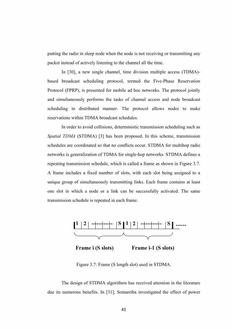
repeating transmission schedule, which is called a frame as shown in Figure 3.7.
A frame includes a fixed number of slots, with each slot being assigned to a
unique group of simultaneously transmitting links. Each frame contains at least
one slot in which a node or a link can be successfully activated. The same
transmission schedule is repeated in each frame.
Frame i-1 (S slots) Frame i (S slots)
S S 212 1
Figure 3.7: Frame (S length slot) used in STDMA.
The design of STDMA algorithms has received attention in the literature
due its numerous benefits. In [31], Somarriba investigated the effect of power
41 41
control algorithm for traffic controlled STDMA. With using power control,
significant throughput improvement is achieved by utilizing interference in
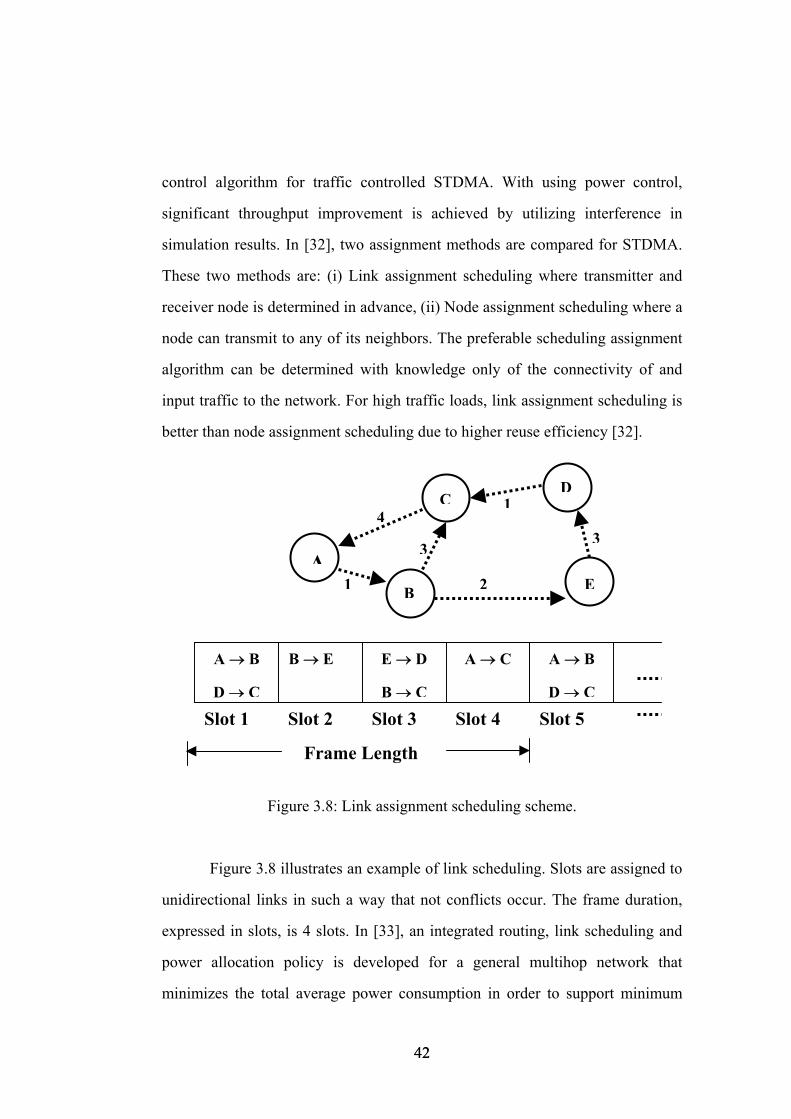
simulation results. In [32], two assignment methods are compared for STDMA.
These two methods are: (i) Link assignment scheduling where transmitter and
receiver node is determined in advance, (ii) Node assignment scheduling where a
node can transmit to any of its neighbors. The preferable scheduling assignment
algorithm can be determined with knowledge only of the connectivity of and
input traffic to the network. For high traffic loads, link assignment scheduling is
better than node assignment scheduling due to higher reuse efficiency [32].
Frame Length
Slot 5
A → B
D → C
Slot 4 Slot 3 Slot 2 Slot 1
A → CE → D
B → C
B → E A → B
D → C
E
DC
B
3
1 2A
34
1
Figure 3.8: Link assignment scheduling scheme.
Figure 3.8 illustrates an example of link scheduling. Slots are assigned to
unidirectional links in such a way that not conflicts occur. The frame duration,
expressed in slots, is 4 slots. In [33], an integrated routing, link scheduling and
power allocation policy is developed for a general multihop network that
minimizes the total average power consumption in order to support minimum
42 42
average rate requirements per link. Their policy can support higher throughputs
than conventional approaches for radio resource allocation, at the expense of
decreased energy efficiency. In [34], link scheduling assignment is studied. The
topology control problem is formulated as a constrained optimization problem
with objective that minimizes the traffic load of the most congested link in the
network. In this paper, the solution takes too long time that cannot be tolerable
for practical networks. So a faster solution is needed. In this thesis, a heuristic
approach for this problem is studied.
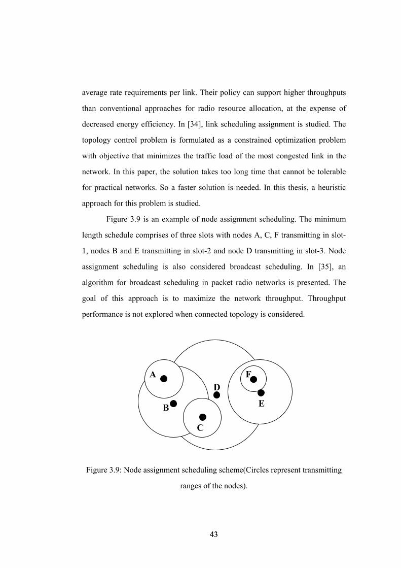
Figure 3.9 is an example of node assignment scheduling. The minimum
length schedule comprises of three slots with nodes A, C, F transmitting in slot-
1, nodes B and E transmitting in slot-2 and node D transmitting in slot-3. Node
assignment scheduling is also considered broadcast scheduling. In [35], an
algorithm for broadcast scheduling in packet radio networks is presented. The
goal of this approach is to maximize the network throughput. Throughput
performance is not explored when connected topology is considered.
A F
C
B
D
E
Figure 3.9: Node assignment scheduling scheme(Circles represent transmitting
ranges of the nodes).
43 43
In this thesis, we work on combined scheduling and routing policy to
create the minimum schedule length in STDMA based ad hoc networks. Our
goal is to determine the shortest frame such that a higher throughput and lower
packet delay are obtained. We use common power (COMPOW) algorithm for
power control. Other power approaches are left as future studies. We use link
scheduling assignment strategy. Description and details of scheduling of
STDMA are given in the last section of this chapter.
3.3 Model Definitions and Assumptions
3.3.1 Network Model
We consider a network consisting of N nodes uniformly located over a given
area. The network topology is modeled by a directed graph G = (V;E) where the
elements of V represent the network nodes and E denotes a radio communication
link between the nodes i and j. We assume that each node in the multihop packet
radio network has a unique identifier, and it contains an omnidirectional radio
transceiver. Due to particular characteristics of military networks as explained in
the first section of this chapter, we consider an ad hoc network where nodes are
organized into a number of non-overlapping clusters. In general, clustering
provides a convenient framework for the operation of an efficient access control
and bandwidth allocation scheme since capacity allocations are localized.
Moreover, clustering architecture reduces the transmission overhead for the
update of routing after topological changes. In the literature, the problem of
cluster formation and maintenance has been studied extensively, especially in the
context of routing [36, 37, 38]. Algorithms for cluster formation and organization
44 44
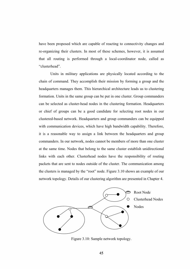
have been proposed which are capable of reacting to connectivity changes and
re-organizing their clusters. In most of these schemes, however, it is assumed
that all routing is performed through a local-coordinator node, called as
“clusterhead”.
Units in military applications are physically located according to the
chain of command. They accomplish their mission by forming a group and the
headquarters manages them. This hierarchical architecture leads us to clustering
formation. Units in the same group can be put in one cluster. Group commanders
can be selected as cluster-head nodes in the clustering formation. Headquarters
or chief of groups can be a good candidate for selecting root nodes in our
clustered-based network. Headquarters and group commanders can be equipped
with communication devices, which have high bandwidth capability. Therefore,
it is a reasonable way to assign a link between the headquarters and group
commanders. In our network, nodes cannot be members of more than one cluster
at the same time. Nodes that belong to the same cluster establish unidirectional
links with each other. Clusterhead nodes have the responsibility of routing
packets that are sent to nodes outside of the cluster. The communication among
the clusters is managed by the “root” node. Figure 3.10 shows an example of our
network topology. Details of our clustering algorithm are presented in Chapter 4.
Root Node
Clusterhead Nodes
Nodes
Figure 3.10: Sample network topology.
45 45
In this thesis, we have assumed fixed topologies only. Reaction to
topological changes by re-clustering and adjusting the links are left for future
studies.
3.3.2 Multiple Access Control (MAC) Model
Typically, ad hoc networks consist of a collection of nodes that try to
communicate with each other over the same radio channel. One problem in this
network is the formulation of Medium Access Control (MAC) protocol. In order
to determine conflict-free channel assignments, we consider Spatial TDMA
(STDMA) scheme due to advantages on power consumption and delay as
explained in previous section. Time is slotted, and slots are grouped into fixed
length frames, which is repeated. Slots are mapped to unidirectional links, which
can occur at the same time. We consider only link scheduling since link
scheduling is preferable due to higher reuse efficiency for high traffic loads. The
entire network is synchronized on frame and slot basis. The slot synchronization
mechanism is not described here, but can be implemented by using root node’s
clock. Topological changes are not considered in this thesis. We also assume that
the following conflict-free communication property always holds:
• A node can either transmit or receive at any given time slot.
• A node can transmit to a single node at any given time slot.
• A node can receive data from only one node at any given time slot.
We use COMPOW as the power control algorithm, which implies that all
nodes select the same transmit power level. In [39], it is shown that COMPOW
46 46
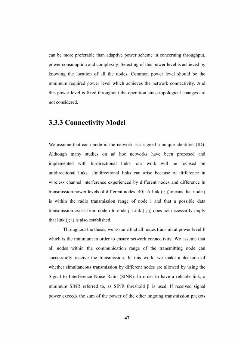
can be more preferable than adaptive power scheme in concerning throughput,
power consumption and complexity. Selecting of this power level is achieved by
knowing the location of all the nodes. Common power level should be the
minimum required power level which achieves the network connectivity. And
this power level is fixed throughout the operation since topological changes are
not considered.
3.3.3 Connectivity Model
We assume that each node in the network is assigned a unique identifier (ID).
Although many studies on ad hoc networks have been proposed and
implemented with bi-directional links, our work will be focused on
unidirectional links. Unidirectional links can arise because of difference in
wireless channel interference experienced by different nodes and difference in
transmission power levels of different nodes [40]. A link (i; j) means that node j
is within the radio transmission range of node i and that a possible data
transmission exists from node i to node j. Link (i; j) does not necessarily imply
that link (j; i) is also established.
Throughout the thesis, we assume that all nodes transmit at power level P
which is the minimum in order to ensure network connectivity. We assume that
all nodes within the communication range of the transmitting node can
successfully receive the transmission. In this work, we make a decision of
whether simultaneous transmission by different nodes are allowed by using the
Signal to Interference Noise Ratio (SINR). In order to have a reliable link, a
minimum SINR referred to, as SINR threshold β is used. If received signal
power exceeds the sum of the power of the other ongoing transmission packets
47 47
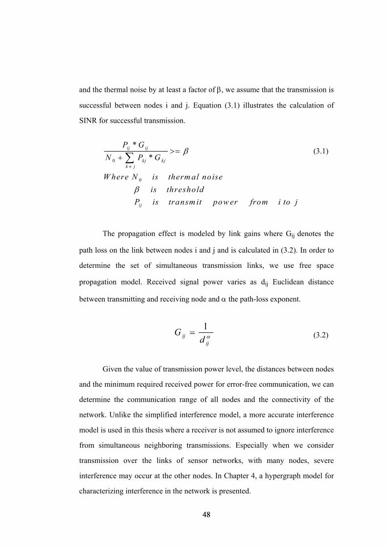
and the thermal noise by at least a factor of β, we assume that the transmission is
successful between nodes i and j. Equation (3.1) illustrates the calculation of
SINR for successful transmission.
(3.1) β>=0
0
**
ij ij
kj kjk j
ij
P GN P G
W here N is therm al noiseis threshold
P is transm it pow er from i to jβ
≠
+ ∑
The propagation effect is modeled by link gains where Gij denotes the
path loss on the link between nodes i and j and is calculated in (3.2). In order to
determine the set of simultaneous transmission links, we use free space
propagation model. Received signal power varies as dij Euclidean distance
between transmitting and receiving node and α the path-loss exponent.
αij
ij dG 1
= (3.2)
Given the value of transmission power level, the distances between nodes
and the minimum required received power for error-free communication, we can
determine the communication range of all nodes and the connectivity of the
network. Unlike the simplified interference model, a more accurate interference
model is used in this thesis where a receiver is not assumed to ignore interference
from simultaneous neighboring transmissions. Especially when we consider
transmission over the links of sensor networks, with many nodes, severe
interference may occur at the other nodes. In Chapter 4, a hypergraph model for
characterizing interference in the network is presented.
48 48
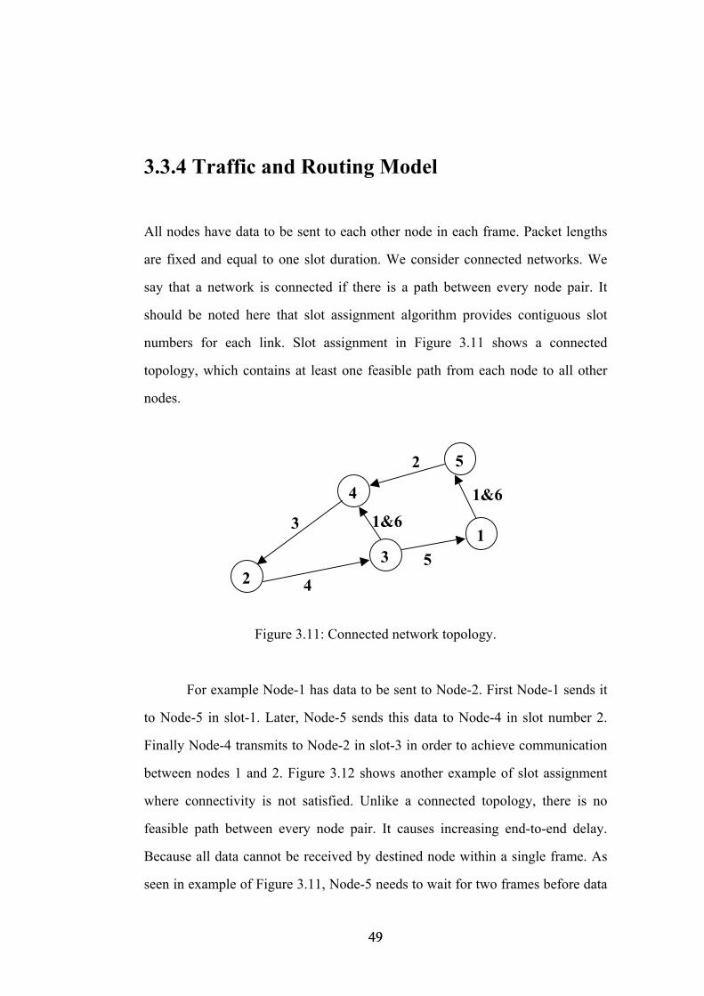
3.3.4 Traffic and Routing Model
All nodes have data to be sent to each other node in each frame. Packet lengths
are fixed and equal to one slot duration. We consider connected networks. We
say that a network is connected if there is a path between every node pair. It
should be noted here that slot assignment algorithm provides contiguous slot
numbers for each link. Slot assignment in Figure 3.11 shows a connected
topology, which contains at least one feasible path from each node to all other
nodes.
1&61&6
2
54
3
2
4
3
5
1
Figure 3.11: Connected network topology.
For example Node-1 has data to be sent to Node-2. First Node-1 sends it
to Node-5 in slot-1. Later, Node-5 sends this data to Node-4 in slot number 2.
Finally Node-4 transmits to Node-2 in slot-3 in order to achieve communication
between nodes 1 and 2. Figure 3.12 shows another example of slot assignment
where connectivity is not satisfied. Unlike a connected topology, there is no
feasible path between every node pair. It causes increasing end-to-end delay.
Because all data cannot be received by destined node within a single frame. As
seen in example of Figure 3.11, Node-5 needs to wait for two frames before data
49 49
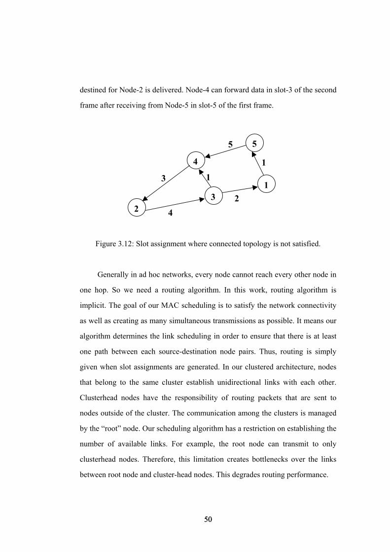
destined for Node-2 is delivered. Node-4 can forward data in slot-3 of the second
frame after receiving from Node-5 in slot-5 of the first frame.
1 1
5
24
3
2
4
3
5
1
Figure 3.12: Slot assignment where connected topology is not satisfied.
Generally in ad hoc networks, every node cannot reach every other node in
one hop. So we need a routing algorithm. In this work, routing algorithm is
implicit. The goal of our MAC scheduling is to satisfy the network connectivity
as well as creating as many simultaneous transmissions as possible. It means our
algorithm determines the link scheduling in order to ensure that there is at least
one path between each source-destination node pairs. Thus, routing is simply
given when slot assignments are generated. In our clustered architecture, nodes
that belong to the same cluster establish unidirectional links with each other.
Clusterhead nodes have the responsibility of routing packets that are sent to
nodes outside of the cluster. The communication among the clusters is managed
by the “root” node. Our scheduling algorithm has a restriction on establishing the
number of available links. For example, the root node can transmit to only
clusterhead nodes. Therefore, this limitation creates bottlenecks over the links
between root node and cluster-head nodes. This degrades routing performance.
50 50
3.3.5 Performance Measures
Like many resource management algorithms, we focus on performing both
fairness and maximization of channel utilization. However, the main
performance measure of our interest is the frame length. The frame length can be
considered as the maximum end-to-end delay in connected topologies. In
particular, the problem of finding an optimal schedule, which is a minimum-
length schedule, is NP-complete [41]. STDMA scheduling eliminates collisions
and removes the need for retransmissions. And spatial reuse of the channel
results in simultaneous link transmissions. Both of them can be translated to a
lower end-to-end delay. The goal of this work is to develop a heuristic algorithm
for topology management based on clustering technique with the goal of
minimizing the frame length. Limitation over some available paths creates
bottleneck links which are not desired. Such bottlenecks may cause network
partitioning due to more power consumption. Fairness is also considered during
our scheduling algorithm.
In the next chapter, we discuss the topology design and scheduling
problems in ad hoc networks.
51 51
Chapter 4
Greedy Heuristic Algorithm for Generating the Desired Topology In wireless ad hoc networks, topology management has a significant importance
due to its effect on network performance. Efficient link scheduling and routing
algorithms are desired goals of achieving an optimal topology. Minimizing frame
length in STDMA-based MAC algorithm results in lower end-to-end delay,
which means maximum channel utilization. Meanwhile, methods of scheduling
need to be based on the traffic requirements at each node as well as the quality of
the links. Therefore, both scheduling and routing could be considered together.
The problem of determining an optimal topology for ad hoc networks is
addressed in [34] by providing an Integer Linear Programming (ILP) formulation
and an example solution in CPLEX. Throughput is maximized in that paper for a
given frame length instead of minimizing the frame length. The ILP approach is
not practical due to long solution times. In this thesis, we focus on minimizing
the STDMA frame length. But the minimum-length-scheduling problem is NP
complete [2]. Therefore, we develop a heuristic solution.
This chapter introduces a new greedy heuristic algorithm for designing a
connected hierarchical topology for ad hoc networks. We then introduce a
52 52
scheduling algorithm for minimum frame length in STDMA-based link
scheduling. The rest of the chapter is organized as follows. Section 4.1 describes
interference model using hypergraphs. All maximal independent sets of the
interference hypergraph are generated in Section 4.2. We continue with forming
hierarchical clustered network structure and then with a detailed description of
our STDMA scheduling algorithm. Finally, we present the distributed heuristic
algorithm and discuss numerical results.
4.1 Interference Hypergraph Model for Ad Hoc
Networks
The interference model widely used in the literature is binary, i.e., constraints
always concern couples of transmitters. However, real-world interference is
additive, i.e., the number of interfering stations should be taken into account for
conflict-free communication. Consider the situation illustrated in Figure 4.1,
where Node-1 is far enough from nodes 2, 4 and 5 to be allowed to use the same
channels. What happens if links A, B, C and D all are attempted to establish
simultaneously? Even though every single node may not be able to generate a
signal strong enough to interfere with Node-1, the combined interference of the
four links would sum up and cause a significant decrease of the signal to noise
ratio for Node-1.
Therefore, binary constraints are not capable for describing many real
world phenomena, and other structures should be employed. For example, an
interference graph could be validly replaced by a hypergraph. In the literature
[41], improved channel assignment algorithms for cellular networks were
53 53
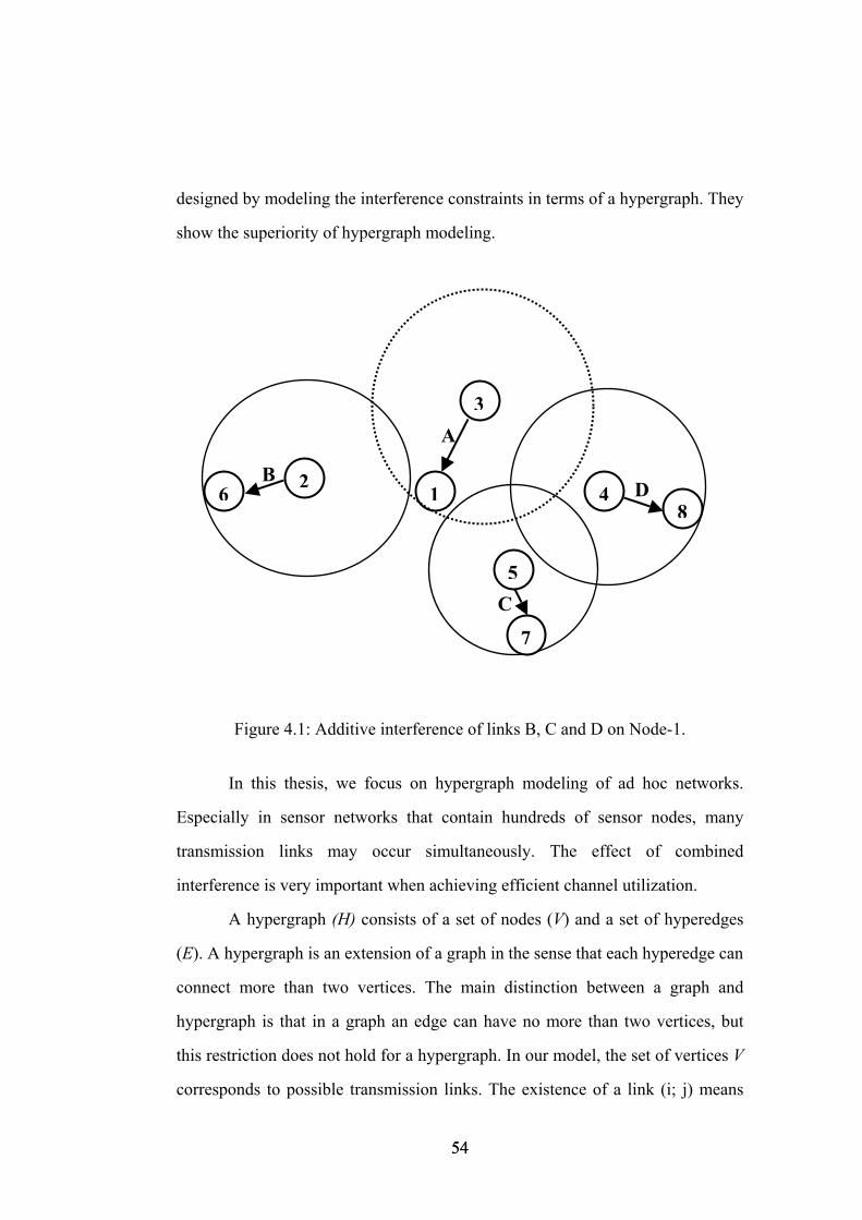
designed by modeling the interference constraints in terms of a hypergraph. They
show the superiority of hypergraph modeling.
C
D
A
B
8
7
6 1 4
5
3
2
Figure 4.1: Additive interference of links B, C and D on Node-1.
In this thesis, we focus on hypergraph modeling of ad hoc networks.
Especially in sensor networks that contain hundreds of sensor nodes, many
transmission links may occur simultaneously. The effect of combined
interference is very important when achieving efficient channel utilization.
A hypergraph (H) consists of a set of nodes (V) and a set of hyperedges
(E). A hypergraph is an extension of a graph in the sense that each hyperedge can
connect more than two vertices. The main distinction between a graph and
hypergraph is that in a graph an edge can have no more than two vertices, but
this restriction does not hold for a hypergraph. In our model, the set of vertices V
corresponds to possible transmission links. The existence of a link (i; j) means
54 54
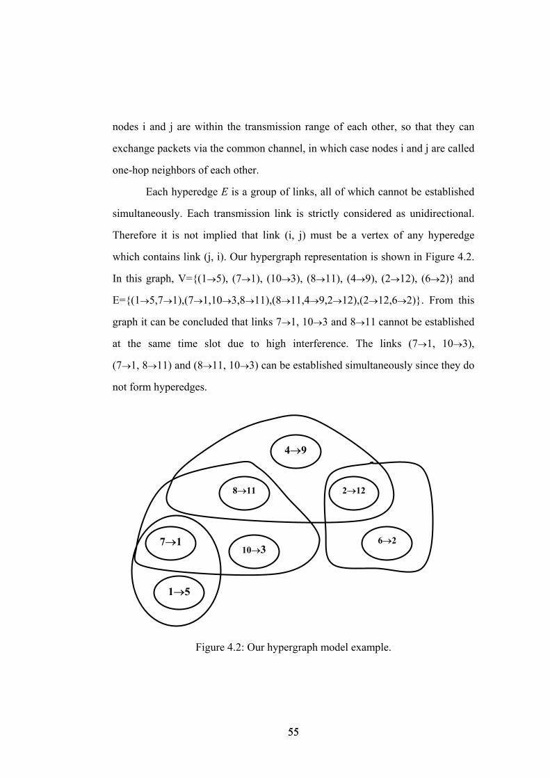
nodes i and j are within the transmission range of each other, so that they can
exchange packets via the common channel, in which case nodes i and j are called
one-hop neighbors of each other.
Each hyperedge E is a group of links, all of which cannot be established
simultaneously. Each transmission link is strictly considered as unidirectional.
Therefore it is not implied that link (i, j) must be a vertex of any hyperedge
which contains link (j, i). Our hypergraph representation is shown in Figure 4.2.
In this graph, V={(1→5), (7→1), (10→3), (8→11), (4→9), (2→12), (6→2)} and
E={(1→5,7→1),(7→1,10→3,8→11),(8→11,4→9,2→12),(2→12,6→2)}. From this
graph it can be concluded that links 7→1, 10→3 and 8→11 cannot be established
at the same time slot due to high interference. The links (7→1, 10→3),
(7→1, 8→11) and (8→11, 10→3) can be established simultaneously since they do
not form hyperedges.
1→5
7→1
4→9
8→11 2→12
6→2 10→3
Figure 4.2: Our hypergraph model example.
55 55
4.2 Generating All Maximal Independent Set of
Hypergraph
In wireless ad hoc networks, spatial reuse of the channel is highly possible.
Efficient channel utilization is a very important performance measure for
multihop wireless networks. In this thesis, we address the problem of minimizing
the frame length for STDMA-based MAC protocols. This objective is achieved
by the maximization of the channel reuse. It also means that more links can be
established in the same time slot. In order to discover simultaneous transmission
links, we take advantage of the property of the maximal independent set.
We call a subset of the vertex set I ⊆ V independent, if it contains no
hyperedges. An independent set I ⊆ V is maximal if any enlargement of the set
makes it dependent. We cannot add any vertex to a Maximal Independent Set
(MIS) without breaking dependency. Therefore, within each of its supersets an
edge can be found. We refer to the problem of finding such a set in a given
hypergraph as the MIS problem. In our algorithm, any group of links that can be
established at the same time slot form an independent set. If adding a new
transmission link into an independent set causes collision, this independent set is
called maximal independent set. In order to maximize of channel reuse, we need
to explore MIS of hypergraph. Assigning these maximal independent sets to time
slots minimize the frame length.
In Figure 4.2, links (1→5) and (10→3) can form an independent set since
they do not contain any hyperedges. And the use of the same time slot for these
two transmissions does not violate the interference constraint. But independent
set which contains links (1→5) and (10→3) is not maximal since we can add a
new transmission link, e.g., (8→11), to this independent set without breaking the
56 56
interference constraint. New independent set {(1→5), (10→3) and (8→11)}
cannot form maximal independent set since enlargement of this set is still
possible. Adding link (2→12) makes the set {(1→5), (10→3) and (8→11)}
maximal independent set. All maximal independent set of given hypergraph in
Figure 4.2 are the follows:
MIS-1: (1→5), (10→3), (8→11), (4→9) and (6→2)
MIS-2: (1→5), (10→3), (8→11) and (2→12)
MIS-3: (7→1), (4→9), (8→11) and (6→2)
MIS-4: (7→1), (10→3), (4→9) and (6→2)
MIS-5: (7→1), (10→3), (4→9) and (2→12)
MIS-6: (1→5), (10→3), (4→9) and (2→12)
Transmission links in the same MIS can be established at the same time
slot without any collision.
An algorithm for determining all maximal independent sets of a
hypergraph is described [41]. We use the same algorithm in order to list all
maximal independent sets of the interference hypergraph. This algorithm uses
three sets:
1) compsub;
2) candidates;
3) not.
The set compsub is a set of vertices all of which form an independent set. The set
candidates is the set of all vertices that are eligible to extend compsub, i.e., each
of which forms an independent set with compsub. The set not is the set of all
vertices which at an earlier stage already served as an extension of the present
configuration of compsub and are now explicitly excluded. A recursively defined
extension operator generates all extensions of the given configuration of
57 57
compsub that it can make with the given set of candidates and that do not contain
any vertex in not. All extensions of compsub containing any vertex in not have
already been generated. The basic mechanism now consists of the following five
steps.
1) Selection of the first vertex in candidates.
2) Adding the selected candidate to compsub.
3) Creating a new set candidates from the old set by removing each
vertex which does not form an independent set with the selected candidate and
compsub and forming a new set not in a similar manner from the old set not.
4) If both not and candidates sets are empty, no further extension of the
present configuration of compsub is possible, nor is there a larger independent
set including the present configuration of compsub in the hypergraph since not is
empty. Hence, compsub contains a maximal independent set, which is generated.
If only candidates is empty, no further extension of the present configuration of
compsub is possible and there exists a larger independent set including the
present configuration of compsub. This independent set has been generated
before. Thus, the algorithm backtracks. If candidates is nonempty (irrespective
of whether not is nonempty), the extension operator is called to operate on the
sets just formed.
5) Upon return, removal of the selected candidate from compsub and its
addition to the old set not.
The worst case time complexity of this algorithm is exponential in the
number of vertices since the number of maximal independent sets grows
exponentially with the number of vertices. But the maximum memory
requirement is P+NP, where P is the maximum size of a maximal independent
set and N is the number of nodes (P≤N). The memory requirement increases
polynomially with the number of vertices.
58 58
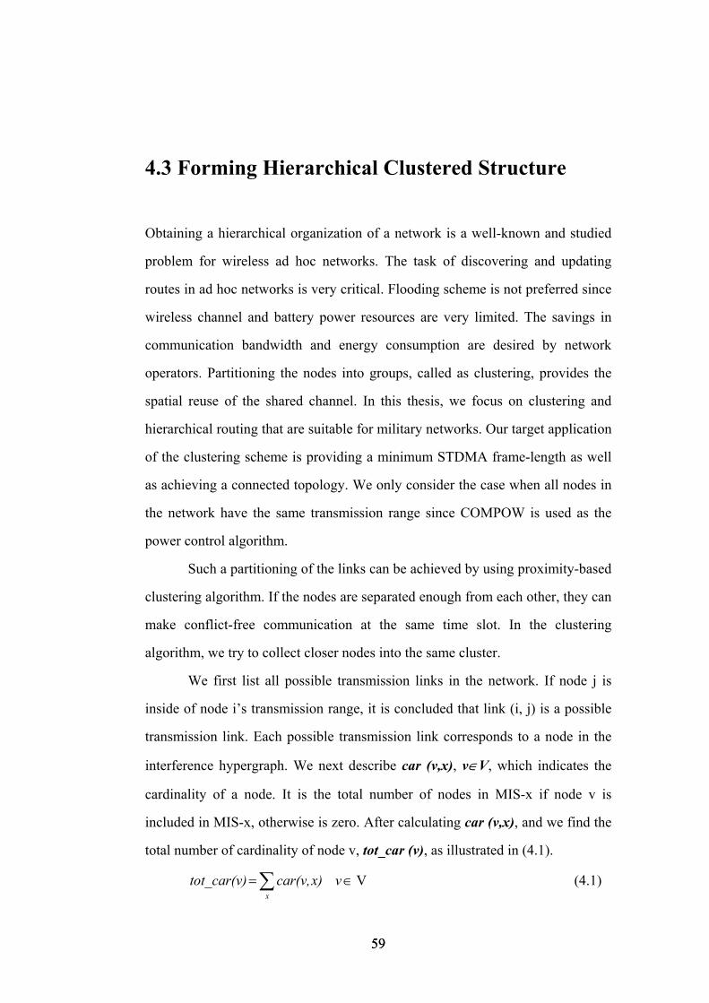
4.3 Forming Hierarchical Clustered Structure
Obtaining a hierarchical organization of a network is a well-known and studied
problem for wireless ad hoc networks. The task of discovering and updating
routes in ad hoc networks is very critical. Flooding scheme is not preferred since
wireless channel and battery power resources are very limited. The savings in
communication bandwidth and energy consumption are desired by network
operators. Partitioning the nodes into groups, called as clustering, provides the
spatial reuse of the shared channel. In this thesis, we focus on clustering and
hierarchical routing that are suitable for military networks. Our target application
of the clustering scheme is providing a minimum STDMA frame-length as well
as achieving a connected topology. We only consider the case when all nodes in
the network have the same transmission range since COMPOW is used as the
power control algorithm.
Such a partitioning of the links can be achieved by using proximity-based
clustering algorithm. If the nodes are separated enough from each other, they can
make conflict-free communication at the same time slot. In the clustering
algorithm, we try to collect closer nodes into the same cluster.
We first list all possible transmission links in the network. If node j is
inside of node i’s transmission range, it is concluded that link (i, j) is a possible
transmission link. Each possible transmission link corresponds to a node in the
interference hypergraph. We next describe car (v,x), v∈V, which indicates the
cardinality of a node. It is the total number of nodes in MIS-x if node v is
included in MIS-x, otherwise is zero. After calculating car (v,x), and we find the
total number of cardinality of node v, tot_car (v), as illustrated in (4.1).
V∈= ∑ v x)car(v, tot_car(v)x
(4.1)
59 59
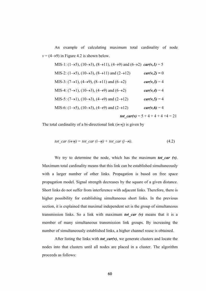
An example of calculating maximum total cardinality of node
v = (4→9) in Figure 4.2 is shown below.
MIS-1: (1→5), (10→3), (8→11), (4→9) and (6→2) car(v,1) = 5
MIS-2: (1→5), (10→3), (8→11) and (2→12) car(v,2) = 0
MIS-3: (7→1), (4→9), (8→11) and (6→2) car(v,3) = 4
MIS-4: (7→1), (10→3), (4→9) and (6→2) car(v,4) = 4
MIS-5: (7→1), (10→3), (4→9) and (2→12) car(v,5) = 4
MIS-6: (1→5), (10→3), (4→9) and (2→12) car(v,6) = 4
tot_car(v) = 5 + 4 + 4 + 4 +4 = 21
The total cardinality of a bi-directional link (i↔j) is given by
tot_car (i↔j) = tot_car (i→j) + tot_car (j→i). (4.2)
We try to determine the node, which has the maximum tot_car (v).
Maximum total cardinality means that this link can be established simultaneously
with a larger number of other links. Propagation is based on free space
propagation model. Signal strength decreases by the square of a given distance.
Short links do not suffer from interference with adjacent links. Therefore, there is
higher possibility for establishing simultaneous short links. In the previous
section, it is explained that maximal independent set is the group of simultaneous
transmission links. So a link with maximum tot_car (v) means that it is a
member of many simultaneous transmission link groups. By increasing the
number of simultaneously established links, a higher channel reuse is obtained.
After listing the links with tot_car(v), we generate clusters and locate the
nodes into that clusters until all nodes are placed in a cluster. The algorithm
proceeds as follows:
60 60

Clustering algorithm: 1. List all nodes of the interference hypergraph in decreasing order, starting with
the one with maximum value of tot_car (.).
2. Take the highest order node whose source or destination is not marked.
3. If this link’s source or destination is assigned to any cluster, Put this link into
that cluster, and Mark source and destination of that link.
4. Else Put that link into a new cluster, and Mark source and destination of that
link.
5. End If all nodes are marked, otherwise Go To Step 2.
Before selecting the root node and the clusterhead nodes, we describe some
lower and upper size limitations over the cluster size and select the root
candidate node. Each node in the networks is the root candidate node.
l = lower level of cluster size.
u = upper level of cluster size.
61 61
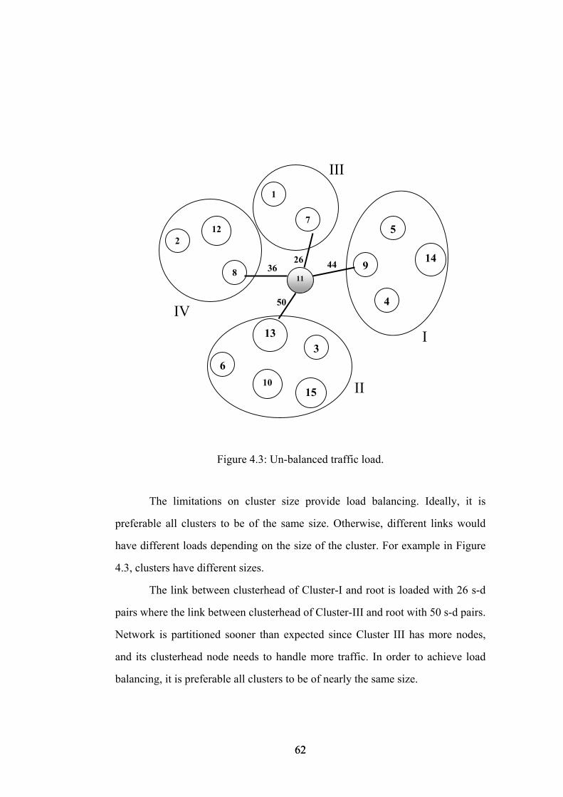
III
II
IV
I
3626
50
44
10
6
15
3
5
4
149
13
118
7
1
2 12
Figure 4.3: Un-balanced traffic load.
The limitations on cluster size provide load balancing. Ideally, it is
preferable all clusters to be of the same size. Otherwise, different links would
have different loads depending on the size of the cluster. For example in Figure
4.3, clusters have different sizes.
The link between clusterhead of Cluster-I and root is loaded with 26 s-d
pairs where the link between clusterhead of Cluster-III and root with 50 s-d pairs.
Network is partitioned sooner than expected since Cluster III has more nodes,
and its clusterhead node needs to handle more traffic. In order to achieve load
balancing, it is preferable all clusters to be of nearly the same size.
62 62
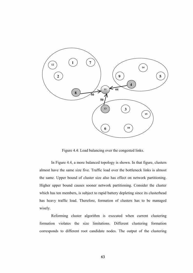
44
5050
11
5
14
4
9
10
315
13
6
12 1 7
8
2
Figure 4.4: Load balancing over the congested links.
In Figure 4.4, a more balanced topology is shown. In that figure, clusters
almost have the same size five. Traffic load over the bottleneck links is almost
the same. Upper bound of cluster size also has effect on network partitioning.
Higher upper bound causes sooner network partitioning. Consider the cluster
which has ten members, is subject to rapid battery depleting since its clusterhead
has heavy traffic load. Therefore, formation of clusters has to be managed
wisely.
Reforming cluster algorithm is executed when current clustering
formation violates the size limitations. Different clustering formation
corresponds to different root candidate nodes. The output of the clustering
63 63
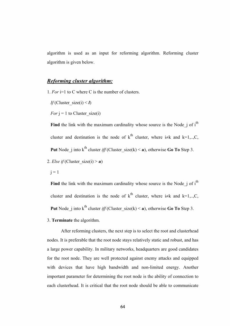
algorithm is used as an input for reforming algorithm. Reforming cluster
algorithm is given below.
Reforming cluster algorithm: 1. For i=1 to C where C is the number of clusters.
If (Cluster_size(i) < l)
For j = 1 to Cluster_size(i)
Find the link with the maximum cardinality whose source is the Node_j of ith
cluster and destination is the node of kth cluster, where i≠k and k=1,..,C,
Put Node_j into kth cluster iff (Cluster_size(k) < u), otherwise Go To Step 3.
2. Else if (Cluster_size(i) > u)
j = 1
Find the link with the maximum cardinality whose source is the Node_j of ith
cluster and destination is the node of kth cluster, where i≠k and k=1,..,C,
Put Node_j into kth cluster iff (Cluster_size(k) < u), otherwise Go To Step 3.
3. Terminate the algorithm.
After reforming clusters, the next step is to select the root and clusterhead
nodes. It is preferable that the root node stays relatively static and robust, and has
a large power capability. In military networks, headquarters are good candidates
for the root node. They are well protected against enemy attacks and equipped
with devices that have high bandwidth and non-limited energy. Another
important parameter for determining the root node is the ability of connection to
each clusterhead. It is critical that the root node should be able to communicate
64 64

with all clusters so that connectivity constraint is satisfied. Like the root node,
clusterhead nodes can be selected by concerning in military chain of command
architecture. In our algorithm, total cardinality of the link between the root
candidate and the clusterhead candidates, defined by (4.2), is used. Root and
clusterhead nodes selection algorithm is described below.
Root and clusterhead nodes selection algorithm:
1. For i =1 to N where N is the number of nodes in networks.
For j =1 to C (i) where C (i) is the number of cluster, built for the root
candidate node-i.
Take each link whose source is the root candidate node-i and destination
is the node of jth cluster.
2. Calculate the total cardinality of that link.
3. Find the link with the maximum cardinality,
4. If the maximum cardinality is equal to zero, i++ and Go To Step 1.
5. Else Choose node-i as the “root” and the destination of that link as the
“clusterhead”.
An example of the hierarchical topology is illustrated in Figure 4.5 where
each node is included in one cluster, and each cluster has one clusterhead for
communication with the root node. The architecture has only one root so as to
manage the connection among clusters.
65 65
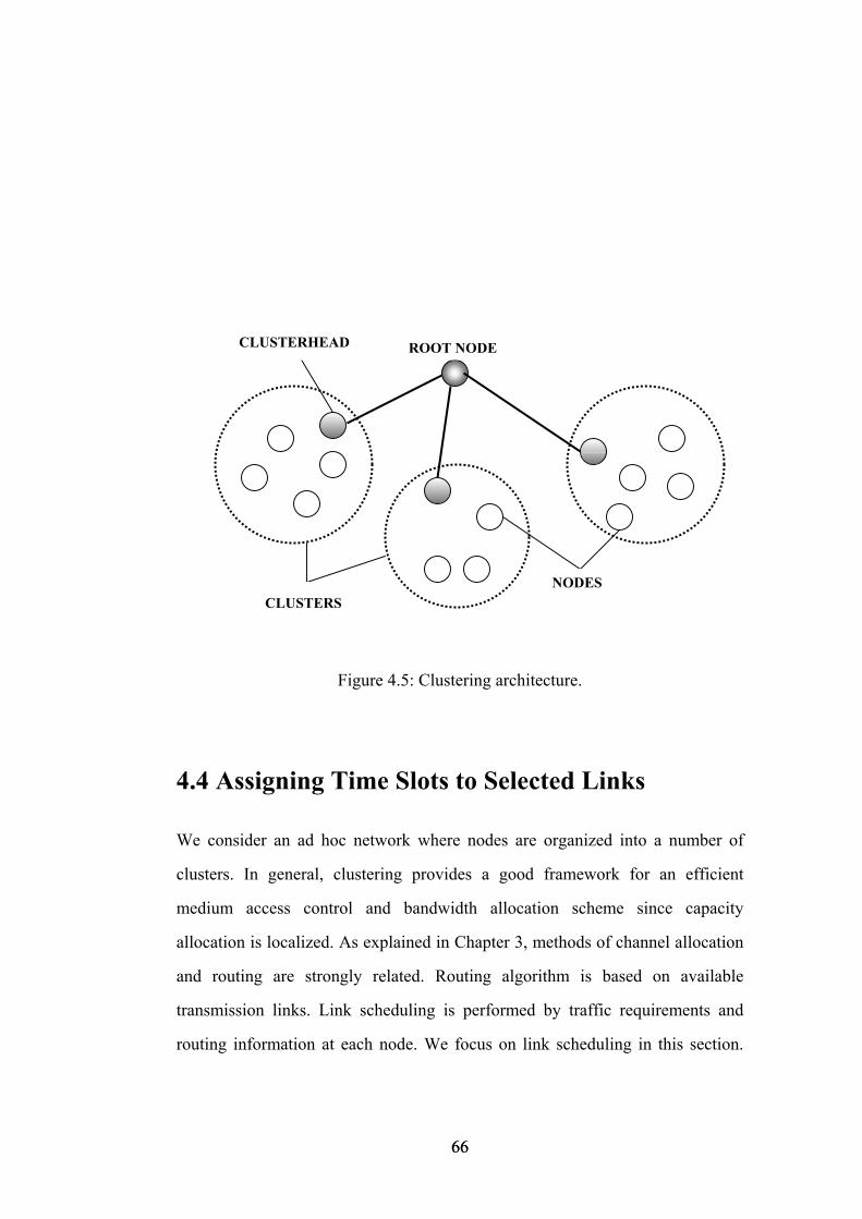
CLUSTERHEAD ROOT NODE
NODESCLUSTERS
Figure 4.5: Clustering architecture.
4.4 Assigning Time Slots to Selected Links We consider an ad hoc network where nodes are organized into a number of
clusters. In general, clustering provides a good framework for an efficient
medium access control and bandwidth allocation scheme since capacity
allocation is localized. As explained in Chapter 3, methods of channel allocation
and routing are strongly related. Routing algorithm is based on available
transmission links. Link scheduling is performed by traffic requirements and
routing information at each node. We focus on link scheduling in this section.
66 66
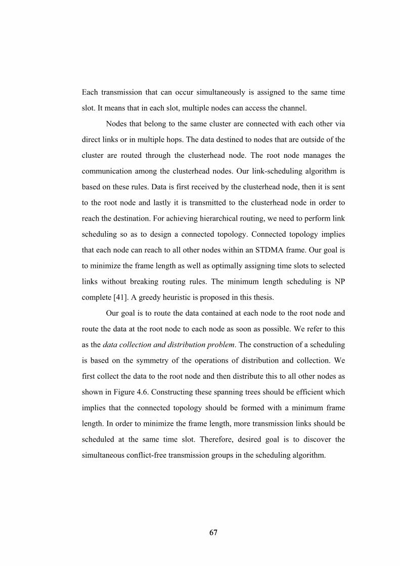
Each transmission that can occur simultaneously is assigned to the same time
slot. It means that in each slot, multiple nodes can access the channel.
Nodes that belong to the same cluster are connected with each other via
direct links or in multiple hops. The data destined to nodes that are outside of the
cluster are routed through the clusterhead node. The root node manages the
communication among the clusterhead nodes. Our link-scheduling algorithm is
based on these rules. Data is first received by the clusterhead node, then it is sent
to the root node and lastly it is transmitted to the clusterhead node in order to
reach the destination. For achieving hierarchical routing, we need to perform link
scheduling so as to design a connected topology. Connected topology implies
that each node can reach to all other nodes within an STDMA frame. Our goal is
to minimize the frame length as well as optimally assigning time slots to selected
links without breaking routing rules. The minimum length scheduling is NP
complete [41]. A greedy heuristic is proposed in this thesis.
Our goal is to route the data contained at each node to the root node and
route the data at the root node to each node as soon as possible. We refer to this
as the data collection and distribution problem. The construction of a scheduling
is based on the symmetry of the operations of distribution and collection. We
first collect the data to the root node and then distribute this to all other nodes as
shown in Figure 4.6. Constructing these spanning trees should be efficient which
implies that the connected topology should be formed with a minimum frame
length. In order to minimize the frame length, more transmission links should be
scheduled at the same time slot. Therefore, desired goal is to discover the
simultaneous conflict-free transmission groups in the scheduling algorithm.
67 67
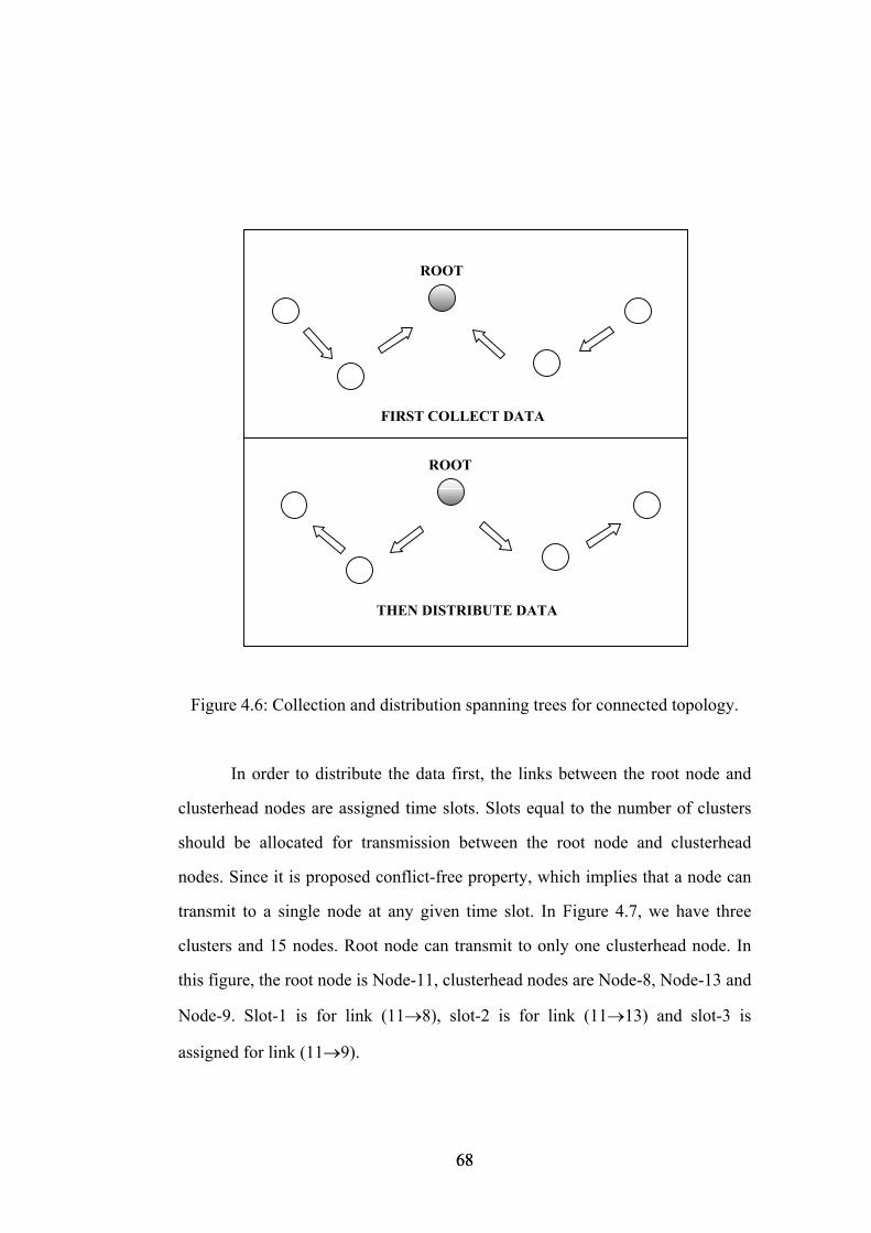
THEN DISTRIBUTE DATA
ROOT
FIRST COLLECT DATA
ROOT
Figure 4.6: Collection and distribution spanning trees for connected topology.
In order to distribute the data first, the links between the root node and
clusterhead nodes are assigned time slots. Slots equal to the number of clusters
should be allocated for transmission between the root node and clusterhead
nodes. Since it is proposed conflict-free property, which implies that a node can
transmit to a single node at any given time slot. In Figure 4.7, we have three
clusters and 15 nodes. Root node can transmit to only one clusterhead node. In
this figure, the root node is Node-11, clusterhead nodes are Node-8, Node-13 and
Node-9. Slot-1 is for link (11→8), slot-2 is for link (11→13) and slot-3 is
assigned for link (11→9).
68 68
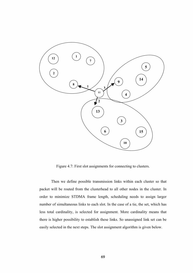
3
2
1
10
6 15
3
5
4
14 9
13
11
8
71
2
12
Figure 4.7: First slot assignments for connecting to clusters.
Then we define possible transmission links within each cluster so that
packet will be routed from the clusterhead to all other nodes in the cluster. In
order to minimize STDMA frame length, scheduling needs to assign larger
number of simultaneous links to each slot. In the case of a tie, the set, which has
less total cardinality, is selected for assignment. More cardinality means that
there is higher possibility to establish these links. So unassigned link set can be
easily selected in the next steps. The slot assignment algorithm is given below.
69 69

Slot assignment algorithm:
1. For i=1 to C where C is the number of clusters
Assign slot-i to the link between the root node and the clusterhead node of
the ith cluster, and Mark clusterhead nodes as reached.
2. List all of possible links from the set of reached nodes to unreached
cluster members.
3. List all simultaneous transmission links set.
4. Select the set with largest number of links or the set with less total
cardinality in the case of a tie.
5. i++ and Assign slot-i to the selected set, and Mark the destinations of the
set as reached.
6. If all nodes are reached Finish, Else Go To Step 2.
An example for the execution of the algorithm is illustrated in Figure 4.8
where possible transmission links are shown. Links from the clusterheads to
unreached nodes are:
Link (8→12), Link (8→2), Link (8→1) and Link (8→7),
Link (9→4), Link (9→14) and Link (9→5),
Link (13→3), Link (13→6), Link (13→10) and Link (13→15).
70 70
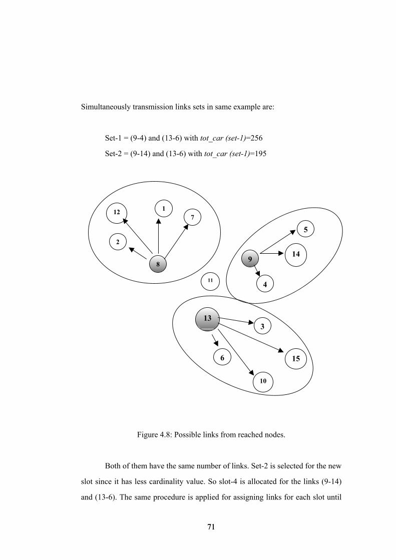
Simultaneously transmission links sets in same example are:
Set-1 = (9-4) and (13-6) with tot_car (set-1)=256
Set-2 = (9-14) and (13-6) with tot_car (set-1)=195
10
6 15
3
5
4
149
13
11
8
71
2
12
Figure 4.8: Possible links from reached nodes.
Both of them have the same number of links. Set-2 is selected for the new
slot since it has less cardinality value. So slot-4 is allocated for the links (9-14)
and (13-6). The same procedure is applied for assigning links for each slot until
71 71
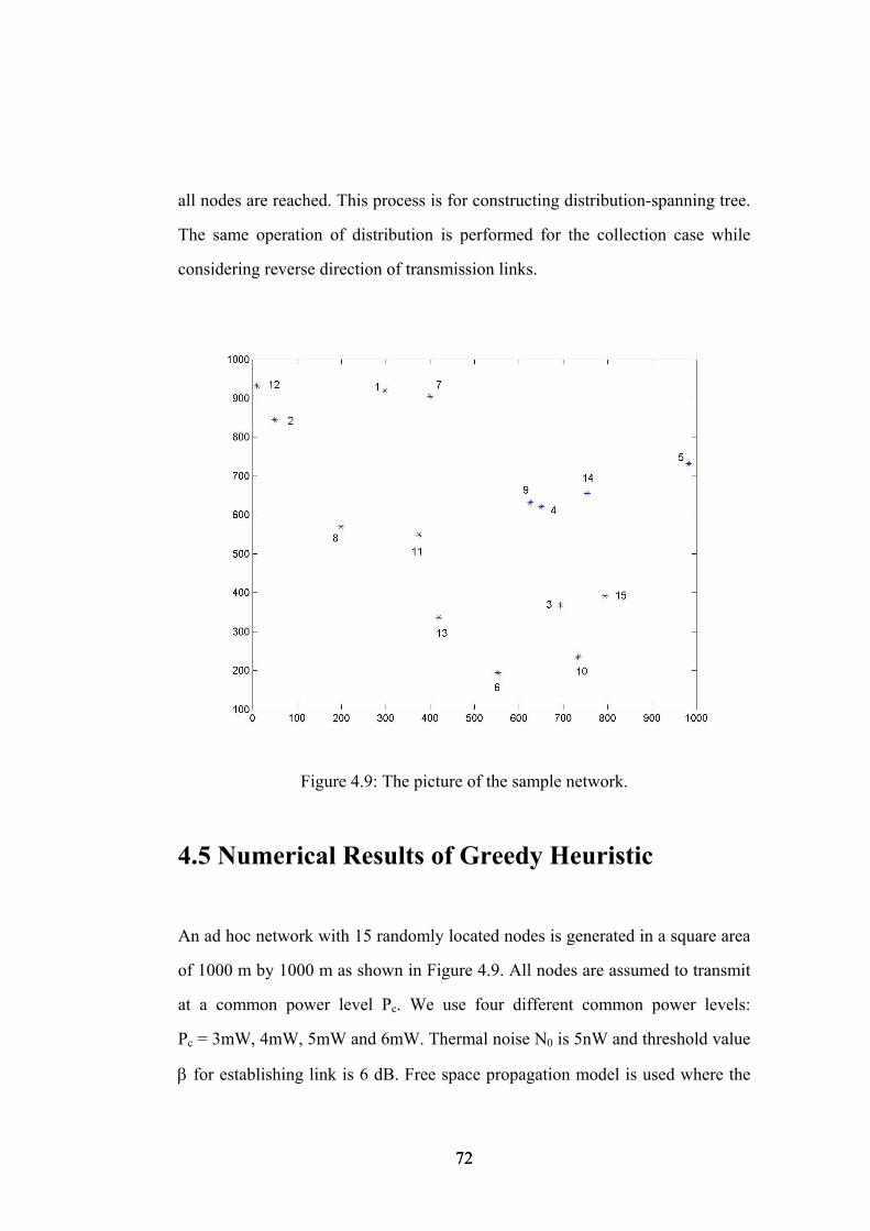
all nodes are reached. This process is for constructing distribution-spanning tree.
The same operation of distribution is performed for the collection case while
considering reverse direction of transmission links.
Figure 4.9: The picture of the sample network.
4.5 Numerical Results of Greedy Heuristic
An ad hoc network with 15 randomly located nodes is generated in a square area
of 1000 m by 1000 m as shown in Figure 4.9. All nodes are assumed to transmit
at a common power level Pc. We use four different common power levels:
Pc = 3mW, 4mW, 5mW and 6mW. Thermal noise N0 is 5nW and threshold value
β for establishing link is 6 dB. Free space propagation model is used where the
72 72
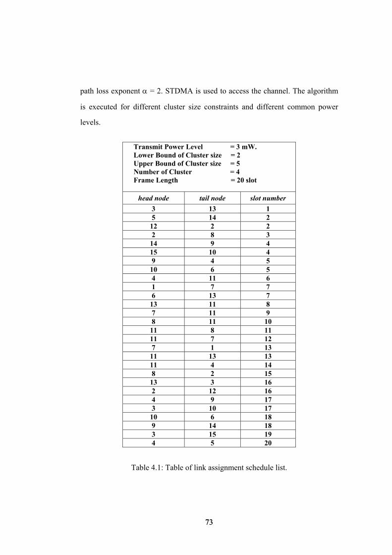
path loss exponent α = 2. STDMA is used to access the channel. The algorithm
is executed for different cluster size constraints and different common power
levels.
Transmit Power Level = 3 mW. Lower Bound of Cluster size = 2 Upper Bound of Cluster size = 5 Number of Cluster = 4 Frame Length = 20 slot
head node tail node slot number 3 13 1 5 14 2
12 2 2 2 8 3
14 9 4 15 10 4 9 4 5
10 6 5 4 11 6 1 7 7 6 13 7
13 11 8 7 11 9 8 11 10
11 8 11 11 7 12 7 1 13
11 13 13 11 4 14 8 2 15
13 3 16 2 12 16 4 9 17 3 10 17
10 6 18 9 14 18 3 15 19 4 5 20
Table 4.1: Table of link assignment schedule list.
73 73
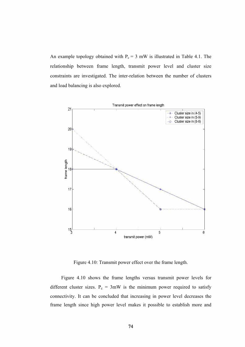
An example topology obtained with Pc = 3 mW is illustrated in Table 4.1. The
relationship between frame length, transmit power level and cluster size
constraints are investigated. The inter-relation between the number of clusters
and load balancing is also explored.
Figure 4.10: Transmit power effect over the frame length.
Figure 4.10 shows the frame lengths versus transmit power levels for
different cluster sizes. Pc = 3mW is the minimum power required to satisfy
connectivity. It can be concluded that increasing in power level decreases the
frame length since high power level makes it possible to establish more and
74 74

longer links. Gain is linearly proportional with the transmit power level in SINR
formula in (3.1), but interference is not linearly dependent since interference
contains constant thermal noise. Since interference does not increase as fast as
the received signal power as the transmit power is increased, it becomes possible
to establish more simultaneous links. Therefore, the minimum transmit power
level is not the optimum when minimizing frame length is considered. More
transmit power has the improvement in the frame length by up to 20% by
reducing the frame length from 20 slot to 16 slot while the power consumption
increases by 66 % by using Pc = 5mW instead 3mW.
In some cases in Figure 4.10, we have possibility to use less transmit
power level in order to get the same frame length, i.e., the frame length
constraint with 18-slot can be achieved by using Pc = 3mW instead 4mW and
16-slot frame length can be achieved by using Pc = 5mW instead 6mW. Power
savings respectively by 33 % and 20 % are achieved for the above frame length
constraints. These power savings cannot be ignorable for battery operated
networks since longevity is a prominent concern.
Determining of the number of clusters is directly related with the
selection of the upper and lower bound of the cluster. From our numerical
results, we can say that there is an optimal value for the number of clusters.
Figure 4.11 shows the optimal value for the number of clusters which is 3 in our
sample network.
Generally speaking, increment in the transmit power level more than a
certain value does not reduce the frame length, i.e., Pc = 5mW is the optimal
value for 2-clustering formation and Pc = 6mW is expected as an optimal power
level for 3-clustering formation. Same conclusion is not observed for 4-
clustering formation.
75 75
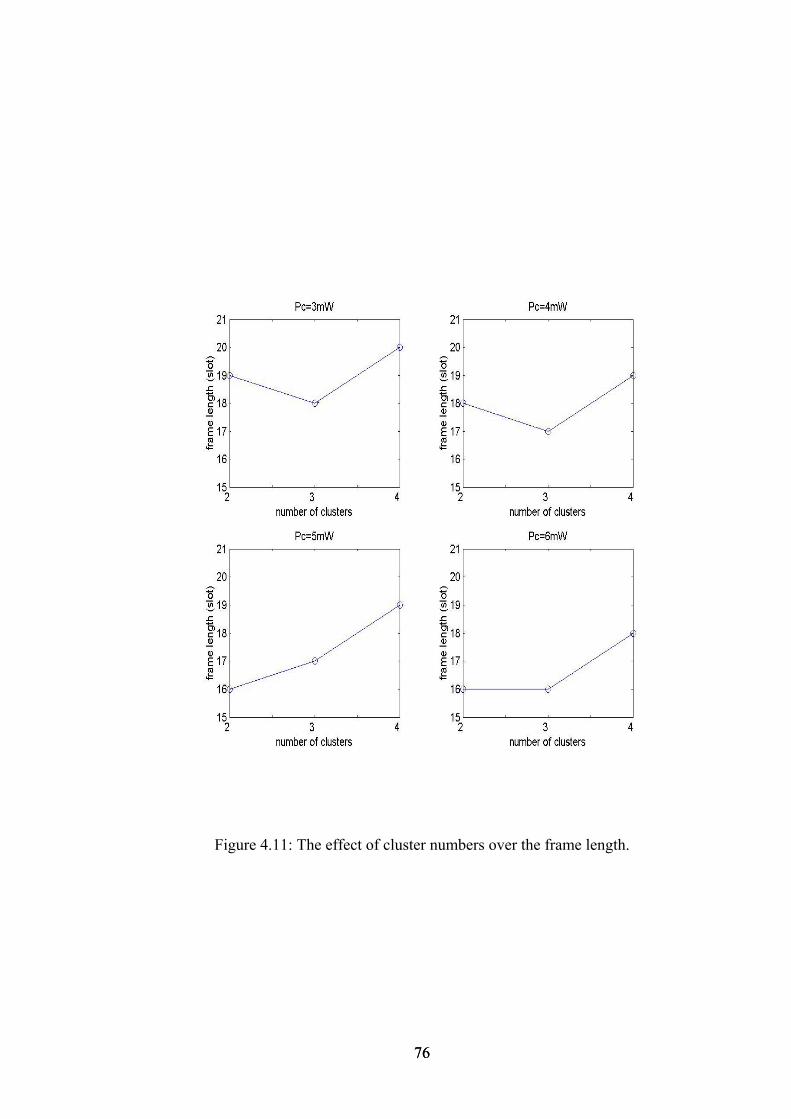
Figure 4.11: The effect of cluster numbers over the frame length.
76 76
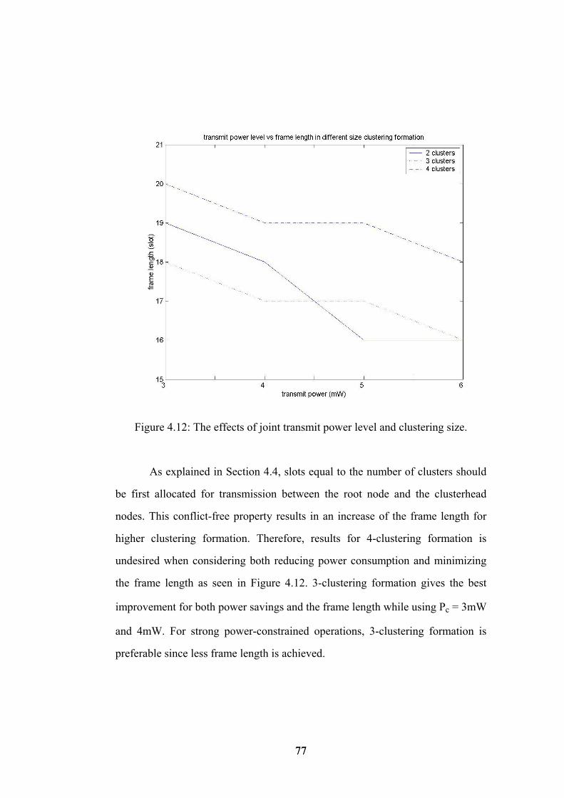
Figure 4.12: The effects of joint transmit power level and clustering size.
As explained in Section 4.4, slots equal to the number of clusters should
be first allocated for transmission between the root node and the clusterhead
nodes. This conflict-free property results in an increase of the frame length for
higher clustering formation. Therefore, results for 4-clustering formation is
undesired when considering both reducing power consumption and minimizing
the frame length as seen in Figure 4.12. 3-clustering formation gives the best
improvement for both power savings and the frame length while using Pc = 3mW
and 4mW. For strong power-constrained operations, 3-clustering formation is
preferable since less frame length is achieved.
77 77
4.6 Distributed Algorithm of Heuristic Solution
In this section, we describe a distributed algorithm which sets up gain and
adjacency matrix used as an input in the proposed algorithms. As mentioned
earlier, ad hoc networks are typically dynamic and hence, computation must be
distributed. In centralized greedy heuristic, we use gain matrix. Because our
problem is based on free space model, distance matrix can be used as a gain
matrix. For empirical results, we need gain matrix that covers the gain value
between each node pairs. The signal strength can be used as a gain value. The
main assumption that we make here is that each host has the capability of
measuring the signal strength and has GPS. We also make two other common
operational assumptions, namely, we assume slot synchronization is ensured by
GPS clocks, that every node has a unique ID. After distributing the data that
include the gain matrix, the algorithm in the previous chapter is executed at the
root node. Then scheduling lists are distributed to all other nodes.
The distributed algorithm is message driven for priori-known N nodes. It is
executed in three phase. In the first phase, each node broadcasts hello(n) message
in lexicographical order for measuring signal strengths. In the next phase, the
root node is responsible for collecting the information of signal strength
measurements and adjacency list matrix. Second phase is based on building a
spanning tree rooted at the root. Each node must keep a table for gain and
adjacency list matrices for the whole network. At the last phase, the root node
propagates the link_scheduling message indicates which link is occurred at
which time slot. In the procedures, we use the following notation for N given
nodes:
• n, node ID.
• hello(n), a hello message broadcasted by node n.
• request(n), request message broadcasted by node n in order to construct
all-pairs gain matrix.
78 78
• parent(n,m), a message shows that node m select node n as a parent.
• signal_strength(n,m), requested information message that carries signal
strength values(gain matrix) to all neighbor nodes measured by child
node m sent to node n and adjacency matrix of node m.
• link_scheduling, broadcast message which includes the link schedule
list.
Firstly, in lexicographical order each node broadcast hello(n) message. In
each time slot, only one node can transmit a hello(n) message. In the first phase,
there is no collision since synchronization is provided. Receiver node can
identify sender node ID. The node receiving this message starts to generate its
own gain matrix by measuring the signal strength. After N slots, all nodes
construct their gain matrix and adjacency lists.
The root node starts the execution of the second phase of the algorithm
by broadcasting a request (n) message. The initiating node becomes the root of
the spanning tree. Each other node joins the spanning tree by designating as its
parent link the link on which it is first contacted. This is called a propagation
order-spanning tree [42]. A node marks the sender of the first received broadcast
as a parent and sends a parent (n,m) message to sender node. Then it broadcasts
the request message further. This node ignores the other broadcast message since
it has already joined the spanning tree. In this way, each node comes to know its
parent and its children in the spanning tree.
Last part of this phase, which is called the collection part, is maintained
by the leaves of spanning tree and goes up to the root node. A node sends a
signal_strength (n,m) message to its parent node after it has added one from all
its children. As a result, when the root node receives the signal_strength (n,m)
messages from its children, it can build the all-pairs gain matrix.
79 79
At the last phase of the algorithm, which is also called the diffusion
phase, the root sends to each of its children link_scheduling message after
executing the scheduling algorithm. Each node, which receives link_scheduling
message, broadcasts it to its children. The algorithm terminates when every node
in the network gets the link_scheduling message.
Since links in ad hoc networks are prone to failure due to interference,
broadcast environment is not reliable. When a node is broadcasting collisions can
occur. Hidden terminal and exposed terminal problems are generally occurring
on broadcast channels. So it might not necessarily result in the building of a
spanning tree. Reliable broadcast is needed for executing our algorithm. In [43],
an adaptive medium access control (MAC) for the reliable broadcast of packets
in wireless networks is proposed. If node s has a broadcast packet to be sent in its
assigned slot, it immediately transmits a request-to-broadcast (RTB) control
packet. Each neighbor of s then responds with a short clear-to-broadcast (CTB)
control packet. Thus all nodes within two hops of node s are informed of its
intent to broadcast in its assigned slot, and refrain from accessing the channel for
the remainder of the slot. Once the channel becomes idle, node s broadcasts its
packet. If channel remains idle throughout the sensing interval, any other node t
with a broadcast packet may attempt to claim the slot by sending its own RTB. In
this case, a neighbor of t responds with a negative-CTB (NCTB) packet if and
only if detects packet collision. The presence of collision indicates that two or
more nodes are contending for the slot. If node t detects no NCTB packets, it
then uses the remainder of the slot to broadcast its packet. Otherwise, its
contention for the slot was unsuccessful and t defers transmission until its
assigned slot, or some later idle slot in the frame as determined by the backoff
scheme, whichever comes first.
80 80
Chapter 5
Conclusion A unified approach to MAC and routing has been studied for topology design in
wireless ad hoc networks. A heuristic solution was proposed by scheduling on
STDMA and by using common power control algorithm. In particular, we
focused on the problem of minimizing end-to-end delay. Moreover, hierarchical
topology was designed by performing clustering formation. The heuristic
algorithm was evaluated through numerical results. A distributed manner of
proposed algorithm was also given in this thesis.
Our focus was on addressing the relations between hierarchical routing
and link scheduling assignments. By executing the heuristic algorithm,
simultaneous transmissions have been assigned to the same time slot while
taking into account the desired topology considerations. Once the hierarchical
topology is designed, routing is simple since the constructed topology has a tree
structure. A new interference model was proposed by using hypergraph
modelling. Clustering formation has been achieved by taking advantage of the
maximal independent set of hypergraph. One key point in this algorithm was the
metric of assigning the time slot to the selected links. Loading and congestion at
each node were not dependent on the scheduling discipline only but also routing
decisions. Fairness was considered and optimal cluster size has been
81 81
investigated. We looked the problem whether the minimum transmit power level
is the optimum one for COMPOW scheme. Generally, the results indicated that
the minimum power level was not the optimum while minimizing frame length
since increasing in power level decreases the frame length. It has been concluded
that there was a trade-off between power savings and the frame length constraint.
Additionally, it was observed that there was a possibility of power saving while
obtaining the same frame length results. Optimal transmit power level could be
achieved for some clustering formation.
From the numerical results, we obtained an optimal value for the number
of clusters. The results for higher clustering formation was undesired when both
power savings and minimizing frame length were considered. For strong power-
constrained operations, the optimum clustering formation was observed.
82 82
Bibliography
[1] R, Nelson and L. Kleinrock, “Spatial TDMA, A collision free multihop
channel access protocol,” IEEE Trans. Comm., vol. COM33, no. 9, Sept 1985.
[2] E. Arıkan, “Some complexity results about packet radio networks,” IEEE
Transaction on Information Theory, vol. IT-30, pp. 910-918, July 1984.
[3] L. Zhou and Z.J. Haas, “Securing ad hoc networks,” in IEEE Networks
Magazine, vol.13, no. 6, pp. 24-30, 1999.
[4] C. Perkins, E. M. Royer and S. R. Das, “Ad hoc on-demand distance vector
routing,” In Internet-Draft, draft-IETF-manet-aodv-06.txt, July 2000.
[5] D. Johnson and D. Maltz, “Dynamic source routing in ad hoc wireless
networks,” in T. Imielinski and H. Korth, editor, Mobile Computing. Kluwer
Academic Publ., 1996.
[6] V. Park and M. S. Corson, “A highly adaptive distributed routing algorithm
for mobile wireless networks,” In Proc. INFOCOM, Kobe, Japan,
April 1997.
[7] C.E. Perkins and P. Bhagwat, “Highly dynamic destination-sequenced
distance-vector routing (DSDV) for mobile computers,” in Comp. Commun.
Rev., Oct. 1994, pp. 234-44.
[8] C.-C. Chiang, “Routing in clustered multihop, mobile wireless networks with
fading channel,” in Proceedings of IEEE SICON ‘97, 1997, pp. 197-211.
[9] S. Murthy and J.J. Garcia-Luna-Aceves, “An efficient routing protocol for
wireless networks,” in ACM Mobile Networks and App. J., Special Issue on
Routing in Mobile Communication Networks, Oct. 1996, pp. 183-97.
[10] Chang, J.-H. and L. Tassiulas, “Energy conserving routing in wireless ad-
hoc networks,” in Proceedings of IEEE INFOCOM ,Tel-Aviv, Israel, 2000.
[11] M. W. Subbarao, “Dynamic power-conscious routing for manets: An initial
approach,” in IEEE Vehicular Technology Conference, 1999, pp.1232–1237.
83 83
[12] S. Singh, M. Woo, and C. S. Raghavendra, “Power aware routing in mobile
ad hoc networks,” in Proceedings of ACM MOBICOM, 1998, pp. 181–190.
[13] R. Ramanathan and R. Rosales-Hain, “Topology control of multihop
wireless networks using transmit power adjustment,” in Proceedings of
INFOCOM, 2000, pp. 404–413.
[14] S. Narayanaswamy, V. Kawadia, R. S. Sreenivas, and P. R. Kumar, “Power
control in ad-hoc networks: Theory, architecture, algorithm and implementation
of the COMPOW protocol,” in European Wireless Conference, 2002.
[15] T. A. ElBatt, S. V. Krishnamurthy, D. Connors, and S. Dao, “Power
management for throughput enhancement in wireless ad-hoc networks,” in IEEE
International Conference on Communications, 2000, pp. 1506–1513.
[16] R. Wattenhofer, L. Li, P. Bahl and Y.-M. Wang, “Distributed topology
control for power efficient operation in multihop wireless ad hoc networks,” in
Proceedings of INFOCOM, 2001, pp. 1388–1397.
[17] Sharad Agarwal and Srikanth V. Krishnamurthy “Distributed power control
in ad hoc wireless networks,” in Proceedings of IEEE International Symposium
on Personal, Indoor and Mobile Radio Communications, San Diego, CA, Oct.,
2001.
[18] Limin Hu, “Topology control for multihop packet radio networks,” in
Proceedings IEEE Transactions on Communications, vol. 41, no. 10, pp. 1474–
1481, October 1993.
[19] Roger Wattenhofer, Li Li, Paramvir Bahl, and Yi-Min Wang, “Distributed
topology control for power efficient operation in multihop wireless ad hoc
networks,” in Proceedings IEEE INFOCOM 2001 Conference, Anchorage,
Alaska, April, 2001,.
[20] L. Li, V. Bahl, Y.M. Wang, and R. Wattenhofer. “Distributed topology
control for power efficient operation in multihop wireless ad hoc networks,” in
Proceedings of IEEE Conference on Computer Communications (INFOCOM),
Apr. 2001.
84 84
[21] Steve A. Borbash and E. Jennings, “Distributed topology control algorithm
for multihop wireless networks,” in 2002 World Congress on Computational
Intelligence, WCCI 2002, Honolulu, Hawaii, May 12-17, 2002.
[22] Ya Xu, Solomon Bien, Yutaka Mori, John Heidemann, and Deborah Estrin
“Toplology control protocols to conserve energy in wireless ad hoc networks,”
submitted for review to IEEE Transactions on Mobile Computing,January 2003.
[23] Q. Li, J. Aslam, and D. Rus, “Online power-aware routing in wireless ad-
hoc networks,” in proceedings of the Seventh Annual International Conference
on Mobile Computing and Networking, July 2001, pp. 97–107.
[24] R. Dube, C. D. Rais, K.Y. Wang, and S. K. Tripathi, “Signal stability based
adaptive routing (SSA) for ad-hoc mobile networks,” in IEEE Personal
Communications, 1997.
[25] J. P. Monks, V. Bhargavan, and W.-M. Hwu, “A power controlled multiple
access protocol for wireless packet networks,” in Proceedings of INFOCOM,
2001, pp. 219–228.
[26] Eun-Sun Jung and Nitin Vaidya, “A power control mac protocol for ad hoc
networks”, in ACM International Conference on Mobile Computing and
Networking (MobiCom), September 2002.
[27] Wei Ye, Jhon Heidemann and Deborah Estrin, “An energy-efficient mac
protocol for wireless sensor networks,” in proceedings of INFOCOM, 2002, pp.
1567-1576.
[28] K. Arisha, Honeywell and M. Youssef, “Energy-aware TDMA based MAC
for sensor networks” in IEEE Workshop on Integrated Management of Power
Aware Communications, Computing and NeTworking (IMPACCT), New York
City, May., 2002.
[29] Chien-Chung Shen, Chavalit Srisathapornphat, Rui Liu, Zhuochuan Huang,
Chaiporn Jaikaeo, and Errol L. Lloyd, “CLTC: A cluster-based topology control
framework for ad hoc networks,” submitted to IEEE TMC, 2003.
85 85
[30] C. Zhu and M. S. Corson, “A five-phase reservation protocol (FPRP) for
mobile ad hoc networks,” in Proceedings of the Conference on Computer
Communications IEEE INFOCOM, San Francisco, California , pp. 322,
March/April 1998.
[31] O. Somarriba, “Multihop packet radio systems in rough terrain,” Licentiate
Thesis, Radio Communication Systems, Dept. of S3, Royal Institute of
Technology, Stockholm, Sweden, Oct. 1995.
[32] J. Groönkvist, “Traffic controlled spatial reuse TDMA in multi-hop radio
networks,” in The Ninth IEEE International Symposium on Personal, Indoor and
Mobile Radio Communications, PIMRC 1998., pages 1203-1207, September
1998.
[33] R. L. Cruz and Arvind V. Santhanam, “Optimal routing, link scheduling and
power control in multihop wireless networks,” in proceedings of IEEE
Conference on Computer Communications (INFOCOM), Apr. 2003.
[34] A. Önal, S. A. Ergin and E. Karaşan, “Ad hoc kablosuz ağlarda güç
denetimi ve yönlendirme algoritmaları ile ağ topolojisi idaresi,” in 10th Signal
Processing and Application Conference (SIU’03), pp , Istanbul, Turkey, June 18-
20, 2003 (in Turkish).
[35] Arunabha Sen and Jeffrey M. Capone, “ Scheduling in packet radio
networks: a new approach,” in GLOBECOM, Rio de Jeneria, 1999.
[36] S. Banerjee and S. Khuller, “A clustering scheme for hierarchical control in
multi-hop wireless networks,” in IEEE INFOCOM 2001, Anchorage, Alaska,
April 2001.
[37] M. Gerla and J.T.-C. Tsai, ‘‘Multicluster, mobile, multimedia radio
network,’’ ACM-Baltzer Journal of Wireless Networks, Vol. 1, No. 3, pp. 255-
265, 1995.
[38] Geng Chen and Ivan Stojmenovic, “Clustering and routing in mobile
wireless networks,” 1999.
86 86
87 87
[39] A. Önal, “Joint topology design with routing and power control in ad hoc
networks,” Ms. Thesis, Department of Electrical and Electronics Engineering
Faculty, Bilkent University, Ankara, 2003.
[40] M. K. Marina and S.R. Das, “Routing performance in the presence of
unidirectional links in multihop wireless networks,” in proceedings ACM
MobiHoc02, pp.12-13, 2002.
[41] S. Sarkar and K. N. Sivarajan, “Hypergraph models for cellular mobile
communication systems,” in IEEE Transactions on Vehicular technology, May
1998.
[42] T. L. Rodeheffer and M. D. Schroeder, “Automatic reconfiguration in
Autonet,” in proceedings of 13th ACM SOSP, pages 183-197, October 1991.
[43] A.D. Myers, V.R. Syrotiuk and G.V. Záruba, “An adaptive medium access
control (MAC) protocol for reliable broadcast in wireless networks,” in
proceedings of the IEEE International Conference on Communications (ICC)
2000, vol. 3, pp. 1692-1696, New Orleans, Louisiana, USA, June, 2000.
Recommended