8/28/2017
1
Topic 1 –Introduction
EE‐4382 Antenna Engineering
Course InstructorDr. Raymond C. RumpfOffice: A‐337Phone: (915) 747‐6958E‐Mail: [email protected]
Outline
• Introduction
• Types of Antennas
• Radiation Mechanism
• Mathematical Preliminaries
• Antenna Parameters
• Communications Link
2Introduction to Antennas
Constantine A. Balanis, Antenna Theory, 3rd Ed., Wiley, 2005.
8/28/2017
2
Introduction
3Introduction to Antennas
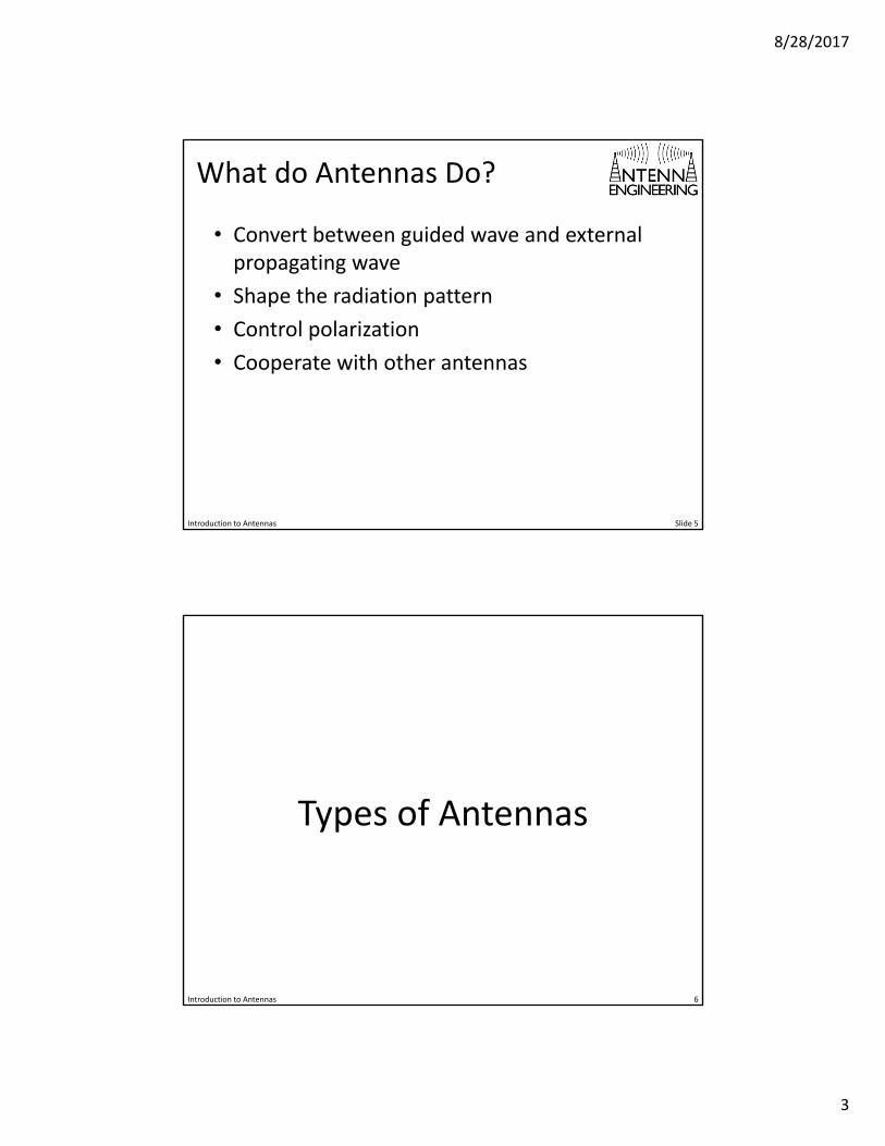
What is an Antenna?
Introduction to Antennas Slide 4
Merriam‐Webster:A usually metallic device (such as a rod or wire) for radiating and receiving radio waves.
IEEE:The part of a transmitting or receiving system that is designed to radiate or to receive electromagnetic waves.
Constantine A. Balanis:The transitional structure between free‐space and a guiding device.
8/28/2017
3
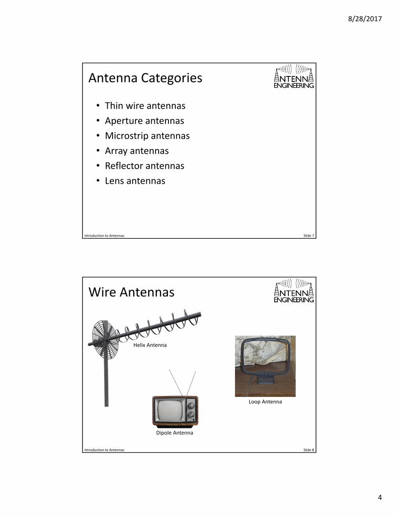
What do Antennas Do?
• Convert between guided wave and external propagating wave
• Shape the radiation pattern
• Control polarization
• Cooperate with other antennas
Introduction to Antennas Slide 5
Types of Antennas
6Introduction to Antennas
8/28/2017
4
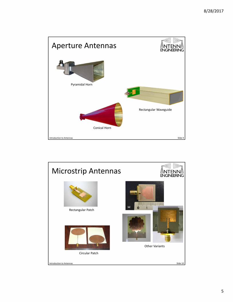
Antenna Categories
• Thin wire antennas
• Aperture antennas
• Microstrip antennas
• Array antennas
• Reflector antennas
• Lens antennas
Introduction to Antennas Slide 7
Wire Antennas
Introduction to Antennas Slide 8
Dipole Antenna
Loop Antenna
Helix Antenna
8/28/2017
5
Aperture Antennas
Introduction to Antennas Slide 9
Conical Horn
Rectangular Waveguide
Pyramidal Horn
Microstrip Antennas
Introduction to Antennas Slide 10
Circular Patch
Other Variants
Rectangular Patch
8/28/2017
6
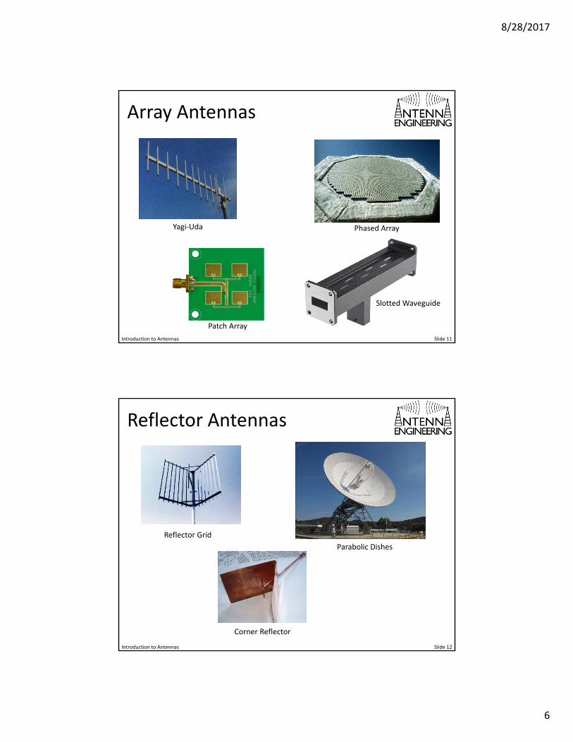
Array Antennas
Introduction to Antennas Slide 11
Patch Array
Phased ArrayYagi‐Uda
Slotted Waveguide
Reflector Antennas
Introduction to Antennas Slide 12
Corner Reflector
Parabolic Dishes
Reflector Grid
8/28/2017
7
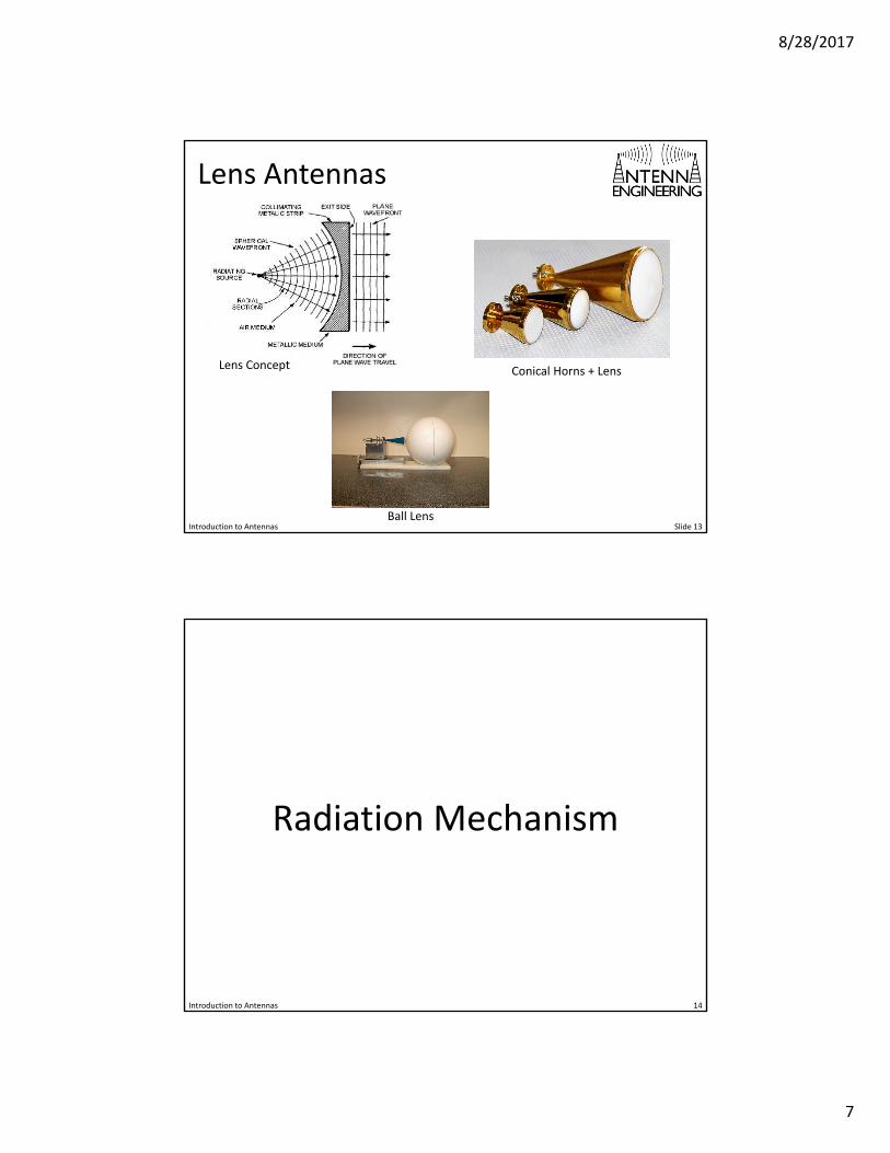
Lens Antennas
Introduction to Antennas Slide 13Ball Lens
Conical Horns + LensLens Concept
Radiation Mechanism
14Introduction to Antennas
8/28/2017
8
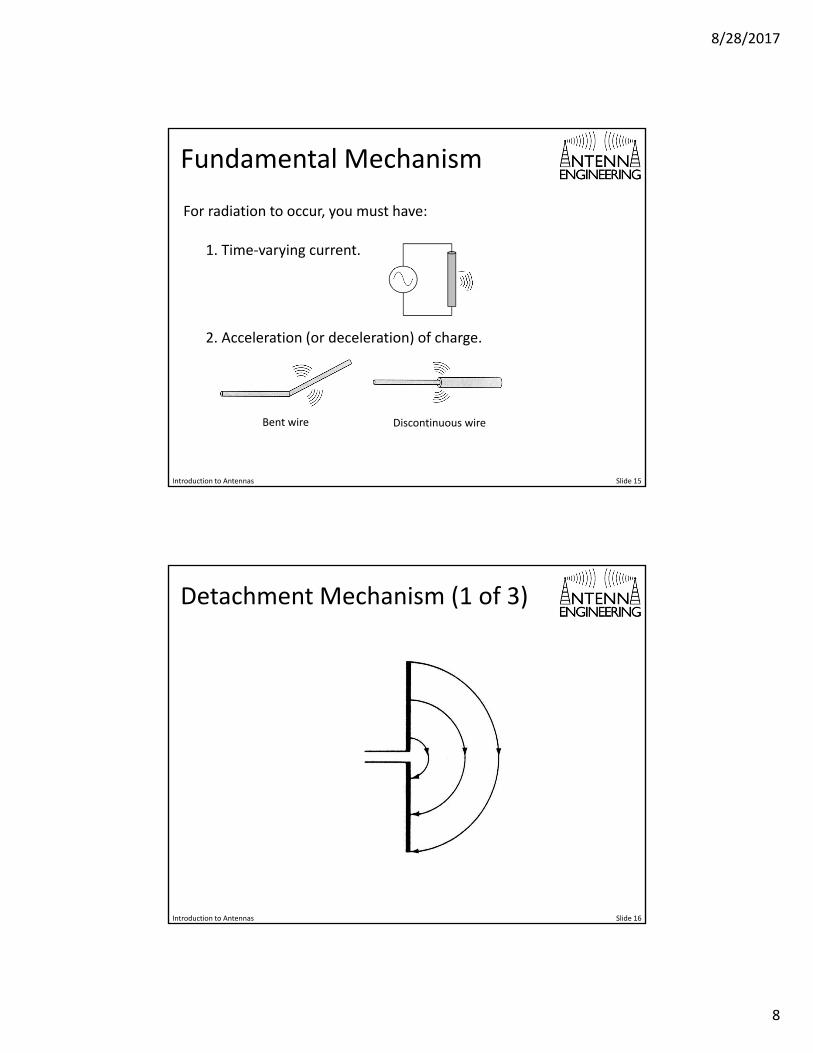
Fundamental Mechanism
Introduction to Antennas Slide 15
For radiation to occur, you must have:
1. Time‐varying current.
2. Acceleration (or deceleration) of charge.
Bent wire Discontinuous wire
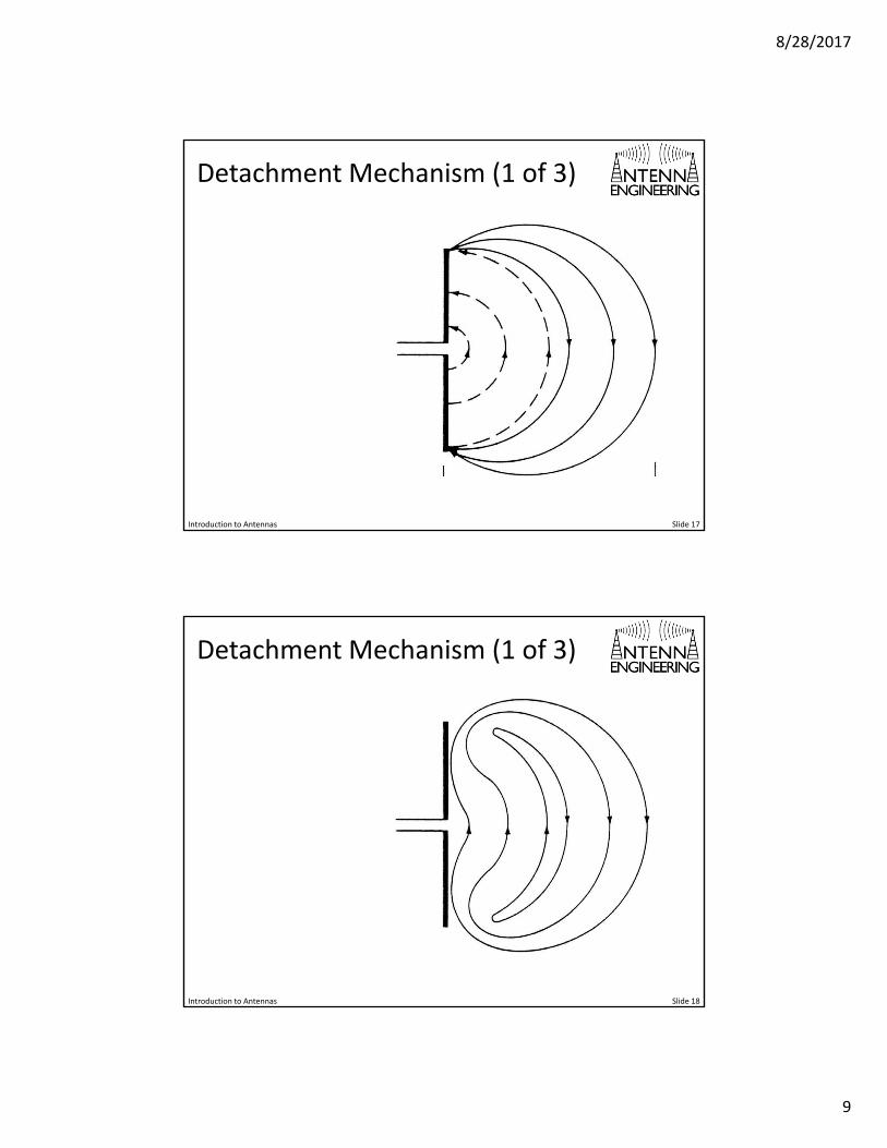
Detachment Mechanism (1 of 3)
Introduction to Antennas Slide 16
8/28/2017
9
Detachment Mechanism (1 of 3)
Introduction to Antennas Slide 17
Detachment Mechanism (1 of 3)
Introduction to Antennas Slide 18
8/28/2017
10
Mathematical Preliminaries
19Introduction to Antennas
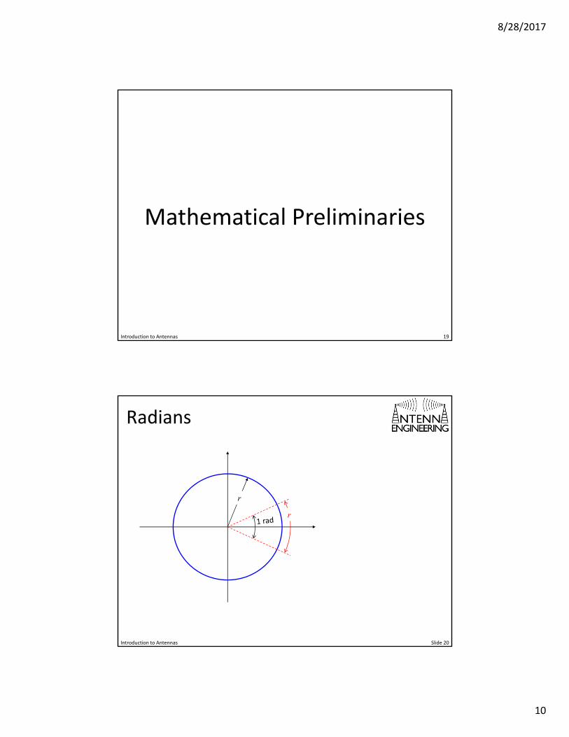
Radians
Introduction to Antennas Slide 20
r
r
8/28/2017
11
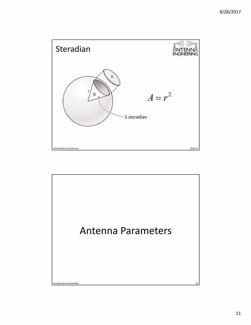
Steradian
Introduction to Antennas Slide 21
2A r
1 steradian
Antenna Parameters
22Introduction to Antennas
8/28/2017
12
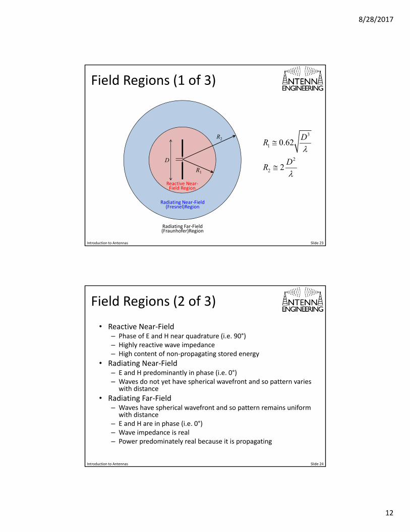
Field Regions (1 of 3)
Introduction to Antennas Slide 23
D
R1
R23
1
2
2
0.62
2
DR
DR
Reactive Near‐Field Region
Radiating Near‐Field (Fresnel)Region
Radiating Far‐Field (Fraunhofer)Region
Field Regions (2 of 3)
• Reactive Near‐Field– Phase of E and H near quadrature (i.e. 90°)– Highly reactive wave impedance– High content of non‐propagating stored energy
• Radiating Near‐Field– E and H predominantly in phase (i.e. 0°)– Waves do not yet have spherical wavefront and so pattern varies
with distance
• Radiating Far‐Field– Waves have spherical wavefront and so pattern remains uniform
with distance– E and H are in phase (i.e. 0°)– Wave impedance is real– Power predominately real because it is propagating
Introduction to Antennas Slide 24
8/28/2017
13
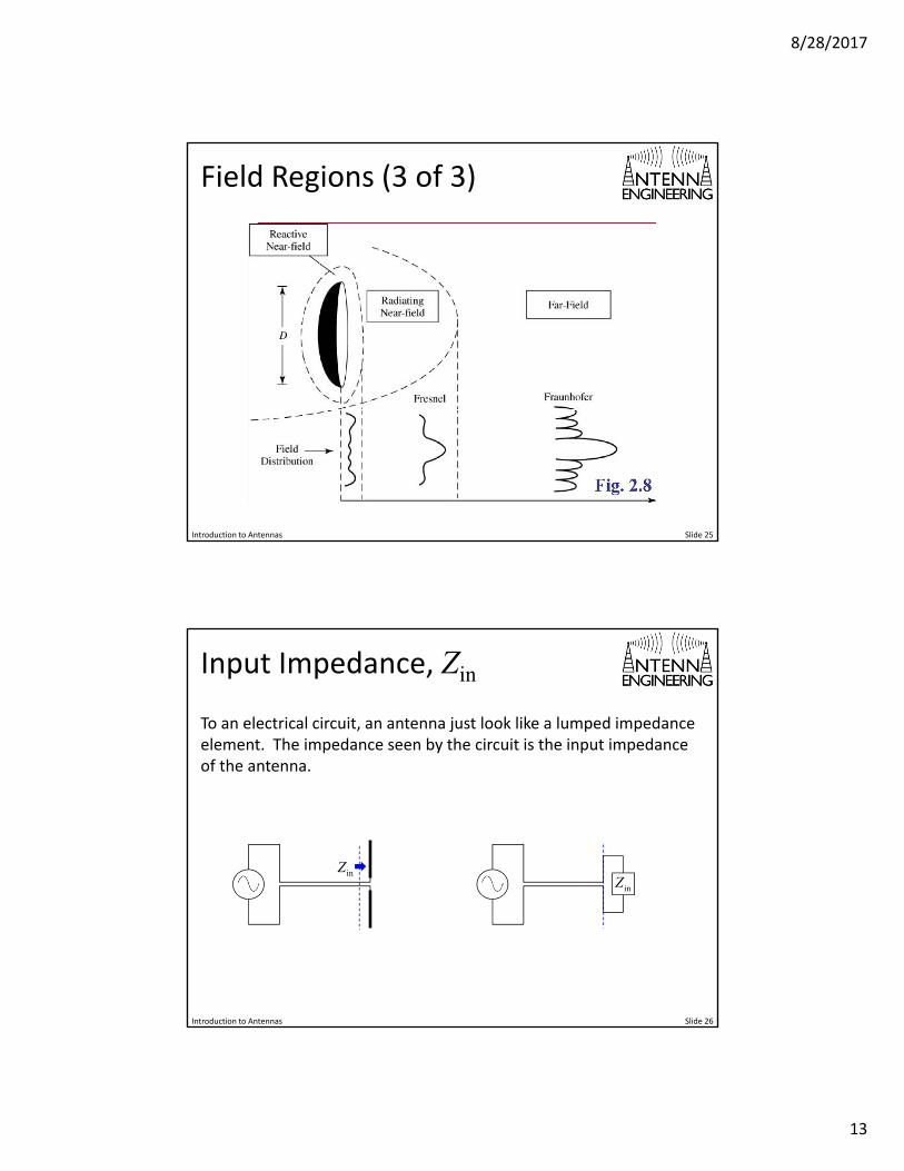
Field Regions (3 of 3)
Introduction to Antennas Slide 25
Input Impedance, Zin
Introduction to Antennas Slide 26
To an electrical circuit, an antenna just look like a lumped impedance element. The impedance seen by the circuit is the input impedance of the antenna.
inZinZ
8/28/2017
14
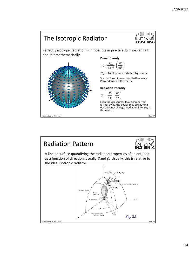
The Isotropic Radiator
Introduction to Antennas Slide 27
Perfectly isotropic radiation is impossible in practice, but we can talk about it mathematically.
Power Density
rad0 2 2
W
4 m
PW
r
Radiation Intensity
0
W
4 Sr
PU
rad total power radiated by sourceP Sources look dimmer from farther away. Power density is this metric.
Even though sources look dimmer from farther away, the power they are putting out does not change. Radiation intensity is this metric.
Radiation Pattern
Introduction to Antennas Slide 28
A line or surface quantifying the radiation properties of an antenna as a function of direction, usually and . Usually, this is relative to the ideal isotropic radiator.
8/28/2017
15
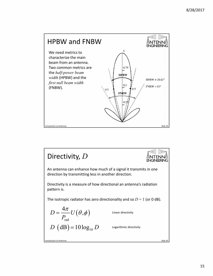
HPBW and FNBW
Introduction to Antennas Slide 29
We need metrics to characterize the main beam from an antenna. Two common metrics are the half-power beam width (HPBW) and the first null beam width (FNBW).
Directivity, D
Introduction to Antennas Slide 30
An antenna can enhance how much of a signal it transmits in one direction by transmitting less in another direction.
Directivity is a measure of how directional an antenna’s radiation pattern is.
The isotropic radiator has zero directionality and so D = 1 (or 0 dB).
rad
10
4,
dB 10log
D UP
D D
Linear directivity
Logarithmic directivity
8/28/2017
16
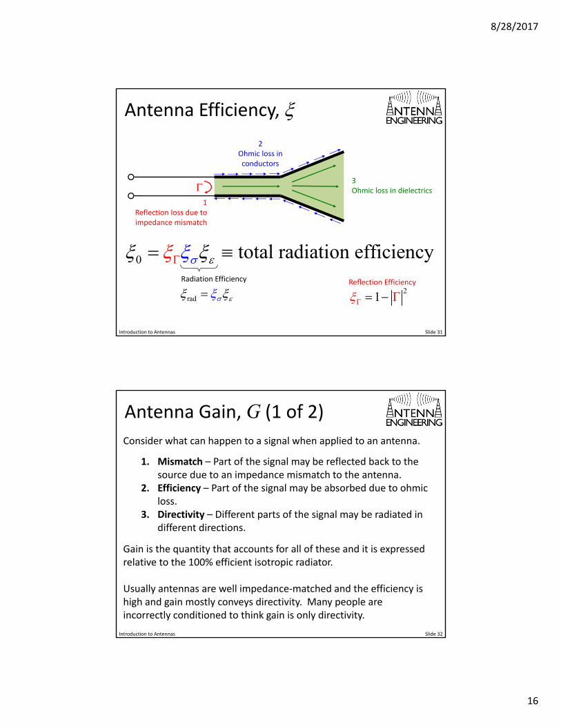
Antenna Efficiency,
Introduction to Antennas Slide 31
1
Reflection loss due toimpedance mismatch
2Ohmic loss in conductors
3Ohmic loss in dielectrics
0 total radiation efficiency
21
Reflection Efficiency
rad Radiation Efficiency
Antenna Gain, G (1 of 2)
Introduction to Antennas Slide 32
Consider what can happen to a signal when applied to an antenna.
1. Mismatch – Part of the signal may be reflected back to the source due to an impedance mismatch to the antenna.
2. Efficiency – Part of the signal may be absorbed due to ohmic loss.
3. Directivity – Different parts of the signal may be radiated in different directions.
Gain is the quantity that accounts for all of these and it is expressed relative to the 100% efficient isotropic radiator.
Usually antennas are well impedance‐matched and the efficiency is high and gain mostly conveys directivity. Many people are incorrectly conditioned to think gain is only directivity.
8/28/2017
17
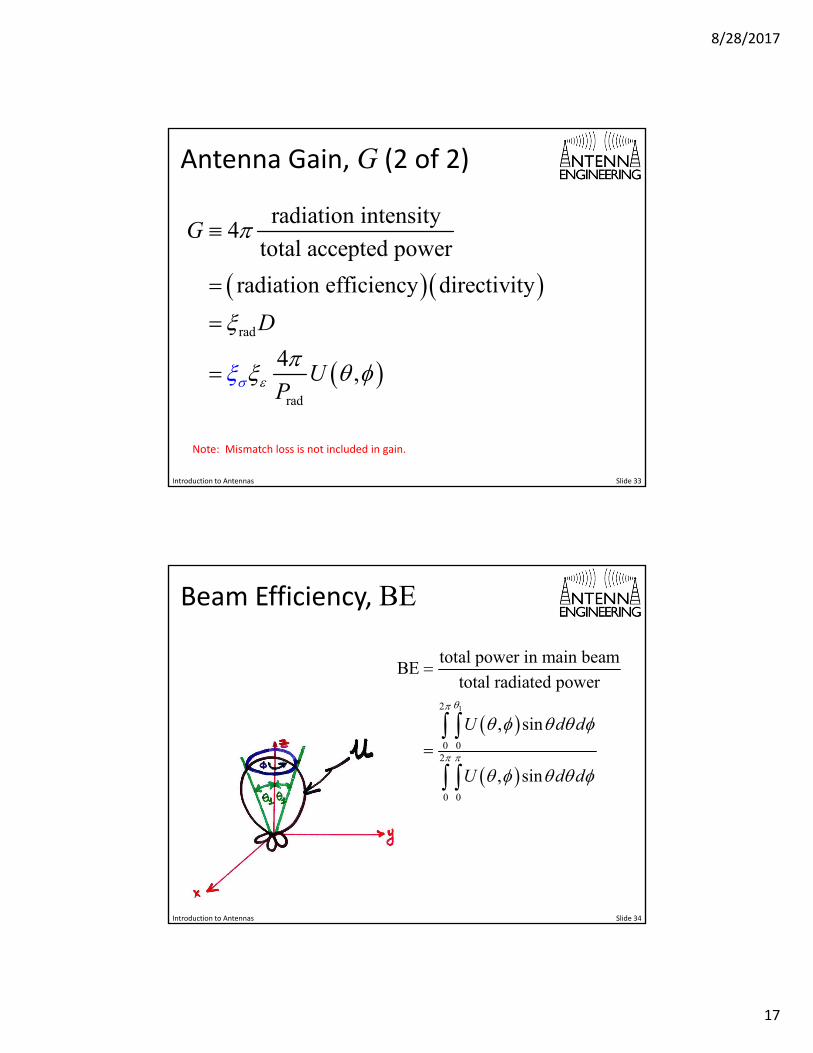
Antenna Gain, G (2 of 2)
Introduction to Antennas Slide 33
rad
rad
radiation intensity4
total accepted power
radiation efficiency directivity
4,
G
D
UP
Note: Mismatch loss is not included in gain.
Beam Efficiency, BE
Introduction to Antennas Slide 34
12
0 02
0 0
total power in main beamBE
total radiated power
, sin
, sin
U d d
U d d
8/28/2017
18
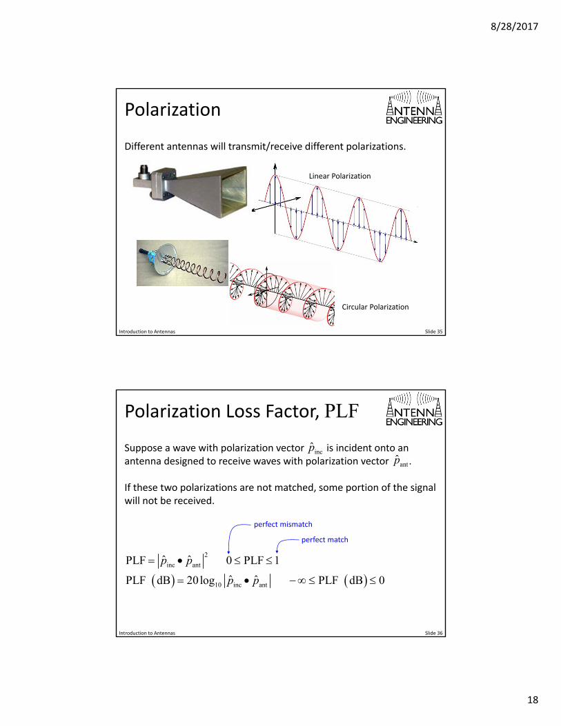
Polarization
Introduction to Antennas Slide 35
Different antennas will transmit/receive different polarizations.
Linear Polarization
Circular Polarization
Polarization Loss Factor, PLF
Introduction to Antennas Slide 36
Suppose a wave with polarization vector is incident onto an antenna designed to receive waves with polarization vector .
If these two polarizations are not matched, some portion of the signal will not be received.
incp̂antp̂
2
inc ant
10 inc ant
ˆ ˆPLF 0 PLF 1
ˆ ˆPLF dB 20log PLF dB 0
p p
p p
perfect match
perfect mismatch
8/28/2017
19
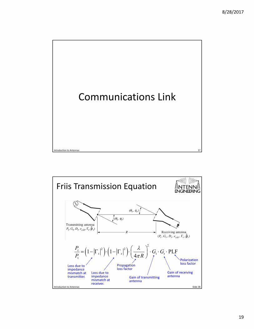
Communications Link
37Introduction to Antennas
Friis Transmission Equation
Introduction to Antennas Slide 38
2
2 2rt r t r
t
1 1 PLF4
PG G
P R
Loss due to impedance mismatch at transmitter.
Loss due to impedance mismatch at receiver.
Propagation loss factor
Gain of transmitting antenna
Gain of receiving antenna
Polarization loss factor
Recommended