116 Surfaceand Coatings Technology,49 (1991) 116—120
Titanium-basedcoatingson steel: dip coatingand plasmaspray
J. Chen,G. Craig, E. Farley and A. SanjurjoSRIInternational, 333 RavenswoodAvenue,Menlo Park, CA 94025-3492(U.S.A.)
Abstract
Coatingsdeposited by plasma sprayingand dip coating were compared. The coating material was a TiNi eutectic. Steel rodsubstrates were coated using each technique. Some of the coated rods were then selectively oxidized or nitrided to form anexternal layer of TiO, or TiN. Cross-sections showing the morphologies of the coatings and the microstructures of the substratesare presented and discussed.
1. Introduction threetechniquesseemedparticularly well suited for ourneeds,andthus we performeda comparativestudy.
The depositionof hard coatingswhich are homoge- Our efforts to coat with a powder slurry were notneous,adherentandcompactis desirablefor a varietyof successful,evenwhenTiNi alloy powdersanddifferentapplications,includingresistanceto aggressivemechani- binderswereusedand the coatedsampleswere treatedcal, chemical and electrochemicalenvironments.Ni- in high vacuumwith a tantalum foil wrappedaroundtridesandoxidesof reactivemetalssuchas titanium are them to scavengeany tracesof oxygen.Thepowdersdidwell knownfor their chemicalresistanceto corrosionin not melt and coat homogeneouslyeven at 1200 °C,aqueouschlorideenvironments.A varietyof techniques presumablybecauseof the presenceof oxygen in thecan be used to deposit thin films of titanium and its coatingmaterial.Therefore,in thispaperwe reportonlycompounds,including physicalandchemicalvapor de- the results obtainedwith conventionalplasmasprayingposition.The practicaluseof thesetechniquesis limited and dip coating.to relatively thin films (a few micrometersthick). For The sampleswere first coatedby eachtechnique,andsomeimportantapplications,a thick pinhole-freecoat- then selectivelyheat treated,nitrided or oxidized.Theing may be desirable or even necessaryto avoid selectivity was obtainedby keepingthe activity of thecatastrophiccorrosion. reactivegas species(NH3 or 02) below that of equi-
In this work we choseto depositcoatingsof a eutectic librium with the compoundformedwith the mostnoblecompositionof a reactivemetal (titanium) and a more metal (NiN or NiO).noble metal (nickel). Nickel can diffuse into (and Wefirst describethe coatingexperiments,followed byprovidegood bondingwith) moststeelsand with most the selectivereactivecoatingstudies.Finally, a metallo-nickel, cobaltandchromium alloys. The reactivemetal, graphicexaminationof thecross-sectionof the coatingstitanium, by itself providesgood corrosionresistance, is presented.particularly in chloride aqueousenvironments.It canalso be selectivelynitrided, oxidized or carburizedtoform a thin, veryadherentlayer for improved corrosion 2. Experimentaldetailsresistance.For depositionof relatively thick coatings(greaterthan 30 i.tm), several coating techniqueshave Theeutecticcomposedof 71.5 wt.% Ti and28.5 wt.%
been used or proposed, including powder sintering, Ni waspreparedby arc melting. The materialwasusedplasmaor arc sprayinganddip coating.Nemotoet a!. for hot dippingandcoatingby plasmasprayafter being[1] havedescribedthe paintingof amixture of titanium crushedto particlesof 0.5mm. AISI 1018 carbonsteeland nickel powdersin a binder on steel substrates, rods (0.63cm in diameter)were usedas the substrates.followedby heattreatmentto 900—1200°Cin a vacuum Thesampleswerewashedwith methanolin anultrasonicto form a protectiveTi—Ni alloy layer. Rondeau[2] and bath and lightly sandedwith No. 600 abrasivepaper.Zhou et al. [3] havedescribeda techniqueto coatmetalsby arc sprayinga Ti—Ni alloy. Allan [4] has described 2.1. Procedurefor dip coatinga hot dipping technique to coat steel substrateswith The dip-coatingapparatusconsisted of a gas-tightTi—Ni eutectic,followed by selectivenitridation. These A1203 chamber,a furnaceand a gas systemcapableof
Elsevier Sequoia, Lausanne
J. Chen et al. / Titanium coatings: dip coating and plasma spray 11 7
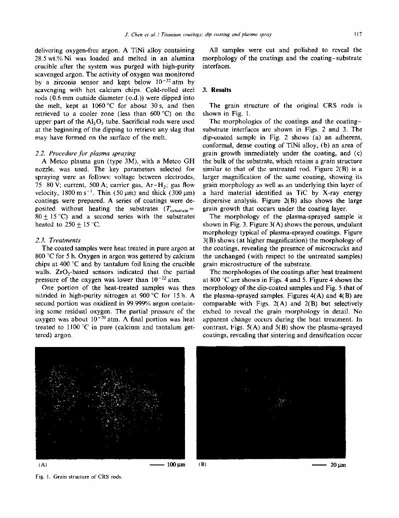
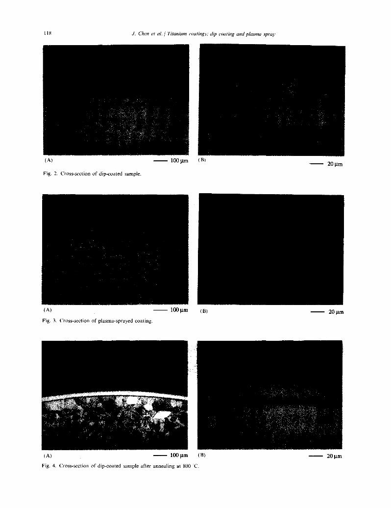
delivering oxygen-freeargon. A TiNi alloy containing All samples were cut and polished to reveal the28.5 wt.%Ni was loaded and melted in an alumina morphologyof the coatingsand the coating—substratecrucible after the systemwas purgedwith high-purity interfaces.scavengedargon.The activity of oxygen wasmonitoredby a zirconia sensor and kept below 10 -22 atm byscavengingwith hot calcium chips. Cold-rolled steel 3. Resultsrods (0.6mm outsidediameter(o.d.))were dippedintothe melt, kept at 1060 °Cfor about 30 s, and then The grain structure of the original CRS rods isretrieved to a cooler zone (less than 600 °C)on the shown in Fig. 1.upperpart of the Al2 03 tube. Sacrificial rodswereused The morphologiesof the coatingsand the coating—at the beginningof the dipping to retrieveany slag that substrateinterfacesare shown in Figs. 2 and 3. Themay haveformed on the surfaceof the melt, dip-coated sample in Fig. 2 shows (a) an adherent,
conformal,densecoatingof TiNi alloy, (b) an areaof2.2. Procedurefor plasmaspraying grain growth immediately under the coating, and (c)
A Metco plasmagun (type 3M), with a Metco GH the bulk of the substrate,which retainsa grain structurenozzle, was used. The key parametersselected for similar to that of the untreatedrod. Figure 2(B) is aspraying were as follows: voltage betweenelectrodes, larger magnification of the samecoating, showing its75—80V; current,500 A; carrier gas,Ar—H2 gas flow grain morphologyas well as an underlyingthin layerofvelocity, 1800m s~.Thin (50 ~.tm)and thick (300 j.tm) a hard material identified as TiC by X-ray energycoatingswere prepared.A seriesof coatingswere de- dispersiveanalysis. Figure 2(B) also shows the largeposited without heating the substrates (TsubsLrate= grain growth that occursunderthe coating layer.80 ±15 °C) and a second series with the substrates The morphology of the plasma-sprayedsample isheatedto 250±15 °C. shownin Fig. 3. Figure3(A) showstheporous,undulant
morphologytypical of plasma-sprayedcoatings.Figure2.3. Treatments 3(B) shows(athighermagnification)the morphologyof
Thecoatedsampleswereheattreatedin pureargonat the coatings,revealingthe presenceof microcracksand800 °Cfor 5 h. Oxygenin argonwasgetteredby calcium the unchanged(with respectto the untreatedsamples)chips at 400°Cand by tantalumfoil lining the crucible grain microstructureof the substrate.walls. Zr02-based sensorsindicated that the partial Themorphologiesof thecoatingsafterheattreatmentpressureof the oxygen was lower than l022 atm. at 800°Care shownin Figs.4 and5. Figure4 showsthe
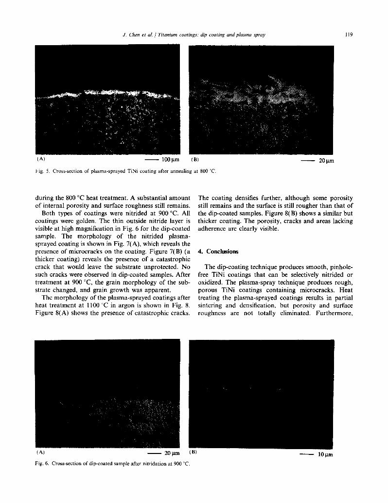
One portion of the heat-treatedsampleswas then morphologyof thedip-coatedsamplesandFig. 5 thatofnitrided in high-purity nitrogen at 900°Cfor 15 h. A the plasma-sprayedsamples.Figures4(A) and4(B) aresecondportion wasoxidized in 99.999%argoncontain- comparablewith Figs. 2(A) and 2(B) but selectivelying some residualoxygen. The partial pressureof the etched to reveal the grain morphologyin detail. Nooxygen was about 1020 atm. A final portion was heat apparentchangeoccurs during the heattreatment. Intreated to 1100 °Cin pure (calcium and tantalum get- contrast,Figs.5(A) and 5(B) show the plasma-sprayedtered) argon. coatings,revealingthat sinteringanddensificationoccur
(A) — 100 jim (B) — 20j.im
Fig. I. Grain structure of CRS rods.
118 J. (‘hen et at. / Titanium coatings: dip coating and plasma spray
(A) — 100jtm (B) —
Fig. 2. Cross-section of dip-coated sample.
(A) — 100jim (B) — 20~tm
Fig. 3. Cross-section of plasma-sprayed coating.
(A) — 100jim (B) — 20 p.m
Fig. 4. Cross-section of dip-coated sample after annealing at 800 C.
J. Chen et at. / Titanium coatings: dip outing and plasma spray 119
(A) — 100jim (B — 20p.m
Fig. 5. Cross-section of plasma-sprayed TiNi coating after annealing at 800 C.
during the 800 °Cheattreatment.A substantialamount The coating densifiesfurther, although some porosityof internalporosityand surfaceroughnessstill remains, still remainsandthe surfaceis still rougherthan that of
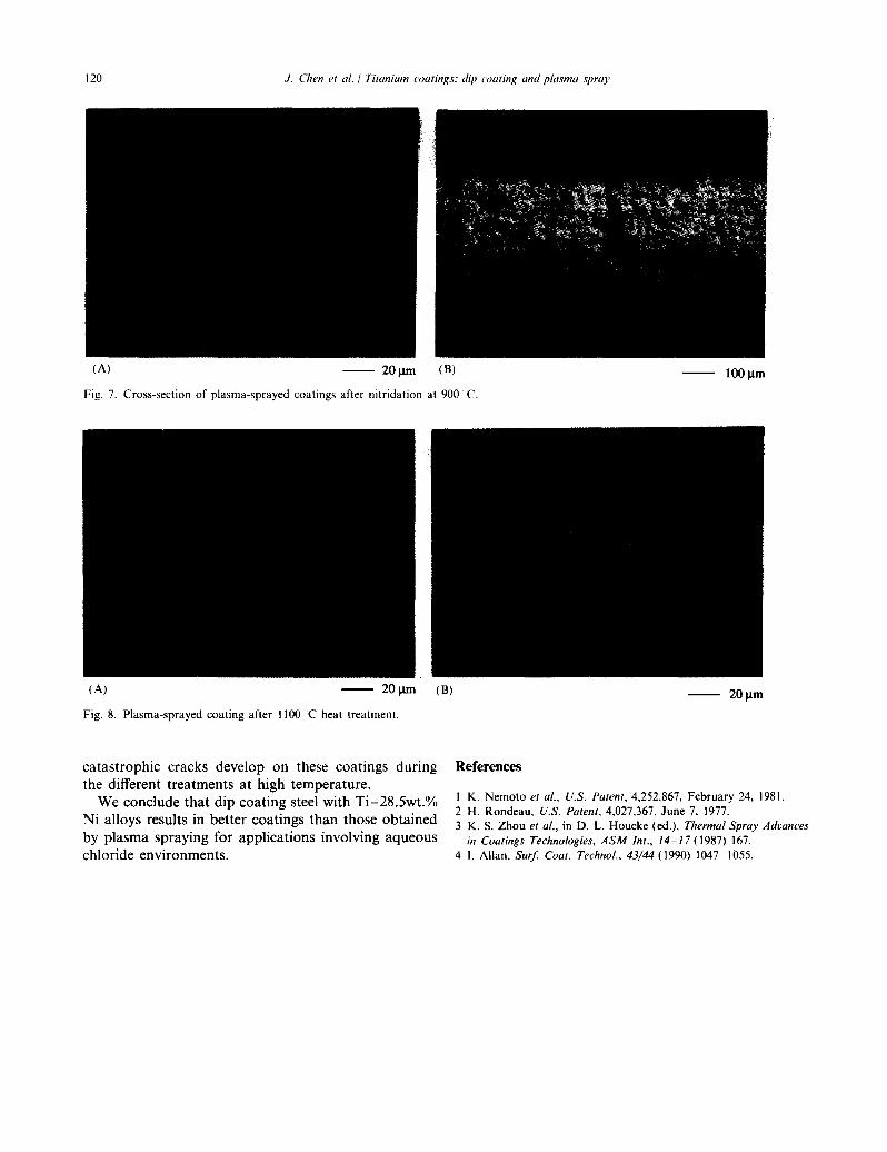
Both types of coatingswere nitrided at 900 °C.All the dip-coatedsamples.Figure 8(B) showsa similarbutcoatingswere golden.The thin outsidenitride layer is thicker coating.The porosity, cracksand areaslackingvisibleat highmagnificationin Fig. 6 for the dip-coated adherenceare clearlyvisible.sample. The morphology of the nitrided plasma-sprayedcoatingis shown in Fig. 7(A), which revealsthepresenceof microcrackson the coating.Figure 7(B) (a 4. Conclusionsthicker coating) revealsthe presenceof a catastrophiccrack that would leave the substrateunprotected.No The dip-coatingtechniqueproducessmooth,pinhole-suchcrackswereobservedin dip-coatedsamples.After free TiNi coatings that can be selectively nitrided ortreatmentat 900 °C, the grain morphologyof the sub- oxidized. The plasma-spraytechniqueproducesrough,stratechanged,and grain growth was apparent. porous TiNi coatings containing microcracks. Heat
Themorphologyof the plasma-sprayedcoatingsafter treating the plasma-sprayedcoatingsresults in partialheattreatmentat 1100°Cin argon is shown in Fig. 8. sintering and densification, but porosity and surfaceFigure 8(A) shows the presenceof catastrophiccracks, roughness are not totally eliminated. Furthermore,
(A) 20j~un (B) — lOp.m
Fig. 6. Cross-section of dip-coated sample after nitridation at 900 ~C.
120 J. (‘lien et at. / Titanium coatings: dip coating and plasma spraJ
(A) — 20p.m (B) — 100 p.m
Fig. 7. Cross-section of plasma-sprayed coatings after nitridation at 900 C.
(A) — 20i.Lm (B) — 20p.m
Fig. 8. Plasma-sprayed coating after 1100 C heat treatment.
catastrophiccracks develop on these coatings during Referencesthe different treatmentsat high temperature.
We concludethat dip coatingsteelwith Ti—28,Swt.% I K. Nemoto et at., U.S. Patent,4,252,867, February 24, 1981.2 H. Rondeau, U.S. Patent,4,027,367, June 7, 1977.
Ni alloys results in bettercoatingsthan thoseobtained 3 K. 5. Zhou et at., in D. L. Houcke (ed), ThermalSprayAdvances
by plasmasprayingfor applicationsinvolving aqueous in CoatingsTechnologies,ASM mt., 14—17(1987)167.
chloride environments, 4 1. Allan, Surf. Coat. Technol.,43/44 (1990)1047—1055.
Recommended