This document, concerning Test Procedures for Residential and Commercial Water Heaters, is a
rulemaking action issued by the Department of Energy. Though it is not intended or expected,
should any discrepancy occur between the document posted here and the document published in
the Federal Register, the Federal Register publication controls. This document is being made
available through the Internet solely as a means to facilitate the public's access to this document.
1
[6450-01-P]
DEPARTMENT OF ENERGY
10 CFR Parts 429, 430 and 431
[Docket No. EERE-2011-BT-TP-0042]
RIN: 1904-AC53
Energy Conservation Program for Consumer Products and Certain Commercial and
Industrial Equipment: Test Procedures for Residential and Commercial Water Heaters
AGENCY: Office of Energy Efficiency and Renewable Energy, Department of Energy.
ACTION: Final rule.
SUMMARY: On November 4, 2013, the U.S. Department of Energy (DOE) issued a notice of
proposed rulemaking (NOPR) to amend its test procedures established under the Energy Policy
and Conservation Act for residential water heaters and certain commercial water heaters, which
serves as the basis for today’s action. This rulemaking fulfills DOE’s statutory obligation for
residential and certain commercial water heaters to review its test procedure for covered products
and equipment at least once every seven years. In addition, this rulemaking satisfies DOE’s
statutory obligation to develop a uniform efficiency descriptor for residential and commercial
water heaters. The test method applies the same efficiency descriptor to all residential and
certain commercial water heaters, and extends coverage to eliminate certain gaps in the current
residential test procedure, updates the simulated-use-test draw pattern, and updates the outlet
water temperature requirement.
2
DATES: The effective date of this rule is [INSERT DATE 365 DAYS AFTER DATE OF
PUBLICATION IN THE FEDERAL REGISTER]. The final rule changes will be mandatory
starting one year after the publication in the Federal Register of a mathematical conversion factor
to convert from the existing efficiency ratings to efficiency ratings under the test procedure
adopted by this final rule, or December 31, 2015, whichever is later.
The incorporation by reference of certain publications listed in this rule is approved by
the Director of the Federal Register as of [INSERT DATE 365 DAYS AFTER DATE OF
PUBLICATION IN THE FEDERAL REGISTER]. Other publications referenced were
approved on March 23, 2009 and May 16, 2012.
ADDRESSES: The docket for this rulemaking is available for review at www.regulations.gov,
including Federal Register notices, public meeting attendee lists and transcripts, comments, and
other supporting documents/materials. All documents in the docket are listed in the
www.regulations.gov index. However, not all documents listed in the index may be publicly
available, such as information that is exempt from public disclosure.
A link to the docket on the www.regulations.gov web page can be found at:
http://www.regulations.gov/#!docketDetail;D=EERE-2011-BT-TP-0042. The
www.regulations.gov web page contains simple instructions on how to access all documents,
including public comments, in the docket.
3
For further information on how to review the docket, contact Ms. Brenda Edwards at
(202) 586-2945 or by email: [email protected].
FOR FURTHER INFORMATION CONTACT: Ms. Ashley Armstrong, U.S. Department of
Energy, Office of Energy Efficiency and Renewable Energy, Building Technologies Office, EE-
5B, 1000 Independence Avenue, SW., Washington, DC, 20585-0121. Telephone: (202) 586-
6590. E-mail: [email protected].
Mr. Eric Stas, U.S. Department of Energy, Office of the General Counsel, GC-71, 1000
Independence Avenue, SW., Washington, DC, 20585-0121. Telephone: (202) 586-9507. E-
mail: [email protected].
SUPPLEMENTARY INFORMATION:
This final rule incorporates by reference the following industry standards into subpart B
of 10 CFR part 430:
ASTM D2156-09, (“ASTM D2156”), Standard Test Method for Smoke Density in Flue
Gases from Burning Distillate Fuels.
Copies of ASTM D2156-09 can be obtained from the American Society for Testing and
Materials International, 100 Barr Harbor Drive, P.O. Box C700, West Conshohocken, PA
19428-2959, or go to http://www.astm.org.
4
Table of Contents
I. Authority and Background II. Summary of the Final Rule
III. Discussion A. Scope
1. Coverage Range of Uniform Metric and Test Procedure 2. Storage Capacity Limits 3. Input Capacity Limits
4. Electric Instantaneous Water Heaters, Gas-fired Heat Pump Water Heaters, and Oil-fired
Instantaneous Water Heaters
B. Uniform Efficiency Descriptor Nomenclature C. Draw Pattern D. Instrumentation E. Test Conditions
1. Outlet Water Temperature 2. Ambient Temperature and Relative Humidity
3. Laboratory Airflow F. Storage Tank Pre-conditioning G. Operational Mode Selection
H. Annual Energy Consumption Calculation I. Conversion of Existing Energy Factor Ratings
J. Full Fuel Cycle K. Certification, Compliance, and Enforcement Issues
1. Storage Volume Requirements 2. First-Hour Rating and Maximum GPM Requirements
3. Ratings for Untested Models L. Reference Standards M. Compliance With Other EPCA Requirements
N. Other Issues IV. Procedural Issues and Regulatory Review
A. Review Under Executive Order 12866 B. Review under the Regulatory Flexibility Act
C. Review Under the Paperwork Reduction Act of 1995 D. Review Under the National Environmental Policy Act of 1969
E. Review Under Executive Order 13132 F. Review Under Executive Order 12988 G. Review Under the Unfunded Mandates Reform Act of 1995 H. Review Under the Treasury and General Government Appropriations Act, 1999 I. Review Under Executive Order 12630
J. Review Under Treasury and General Government Appropriations Act, 2001 K. Review Under Executive Order 13211 L. Review Under Section 32 of the Federal Energy Administration Act of 1974 M. Congressional Notification
V. Approval of the Office of the Secretary
5
I. Authority and Background
Title III, Part B1 of the Energy Policy and Conservation Act of 1975 (“EPCA” or “the
Act”), Pub. L. 94–163 (42 U.S.C. 6291–6309, as codified) sets forth a variety of provisions
designed to improve energy efficiency and established the Energy Conservation Program for
Consumer Products Other Than Automobiles.2 These include residential water heaters, one
subject of this rulemaking. (42 U.S.C. 6292(a)(4)) Title III, Part C3 of EPCA, Pub. L. 94–163
(42 U.S.C. 6311–6317, as codified), added by Pub. L. 95–619, Title IV, Sec. 441(a), established
the Energy Conservation Program for Certain Industrial Equipment, which includes the
commercial water-heating equipment that is another subject of this rulemaking. (42 U.S.C.
6311(1)(K))
Under EPCA, energy conservation programs generally consist of four parts: (1) testing;
(2) labeling; (3) establishing Federal energy conservation standards; and (4) certification and
enforcement procedures. The testing requirements consist of test procedures that manufacturers
of covered products and equipment must use as the basis for certifying to DOE that their
products and equipment comply with the applicable energy conservation standards adopted
pursuant to EPCA and for making other representations about the efficiency of those products.
(42 U.S.C. 6293(c); 42 U.S.C. 6295(s); 42 U.S.C. 6314) Similarly, DOE must use these test
requirements to determine whether the products comply with any relevant standards promulgated
under EPCA. (42 U.S.C. 6295(s))
1 For editorial reasons, upon codification in the U.S. Code, Part B was redesignated as Part A.
2 All references to EPCA in this document refer to the statute as amended through the American Energy
Manufacturing Technical Corrections Act (AEMTCA), Public Law 112–210 (Dec. 18, 2012). 3 For editorial reasons, upon codification in the U.S. Code, Part C was redesignated Part A–1.
6
Under 42 U.S.C. 6293, EPCA sets forth the criteria and procedures that DOE must follow
when prescribing or amending test procedures for residential water heaters. EPCA provides, in
relevant part, that any test procedures prescribed or amended under this section must be
reasonably designed to produce test results which measure energy efficiency, energy use, or
estimated annual operating cost of a covered product during a representative average use cycle or
period of use, and must not be unduly burdensome to conduct. (42 U.S.C. 6293(b)(3)) In
addition, if DOE determines that a test procedure amendment is warranted, it must publish
proposed test procedures and offer the public an opportunity to present oral and written
comments on them. (42 U.S.C. 6293(b)(2))
For commercial water heaters, EPCA requires that if the test procedure referenced in the
American Society of Heating, Refrigerating, and Air-Conditioning Engineers (ASHRAE)
Standard 90.1, “Energy Standard for Buildings Except Low-Rise Residential Buildings,” is
updated, DOE must amend its test procedure to be consistent with the updated test procedure
unless DOE determines by rule published in the Federal Register and supported by clear and
convincing evidence that the amended test procedure is not reasonably designed to produce test
results which reflect the energy efficiency, energy use, or estimated operating costs of that type
of ASHRAE equipment during a representative average use cycle. In addition, DOE must
determine that the amended test procedure is not unduly burdensome to conduct. (42 U.S.C.
6314(a)(2) and (4))
In any rulemaking to amend a test procedure, DOE must determine to what extent, if any,
the proposed test procedure would alter the product’s measured energy efficiency. (42 U.S.C.

7
6293(e)(1)) If DOE determines that the amended test procedure would alter the measured
efficiency of a covered product, DOE must amend the applicable energy conservation standard
accordingly. (42 U.S.C. 6293(e)(2))
Further, the Energy Independence and Security Act of 2007 (EISA 2007) amended EPCA
to require that DOE must review test procedures for all covered products at least once every
seven years and either amend test procedures (if the Secretary determines that amended test
procedures would more accurately or fully comply with the requirements of 42 U.S.C.
6293(b)(3) for residential products or 42 U.S.C. 6314(a)(2)-(3) for commercial equipment) or
publish notice in the Federal Register of any determination not to amend a test procedure. (42
U.S.C. 6293(b)(1)(A); 42 U.S.C. 6314(a)(1)(A)) Under this requirement, DOE must review the
test procedures for residential water heaters not later than December 19, 2014 (seven years after
the enactment of EISA 2007), and DOE must review the test procedures for commercial water
heaters not later than May 16, 2019 (seven years after the last final rule for commercial water
heater test procedures4). The final rule resulting from this rulemaking will satisfy the
requirement to review the test procedures for residential and certain commercial water heaters
every seven years.
DOE’s test procedure for residential water heaters is found in the Code of Federal
Regulations (CFR) at 10 CFR 430.23(e) and 10 CFR part 430, subpart B, appendix E. The test
procedure includes provisions for determining the energy efficiency (energy factor (EF)), as well
as the annual energy consumption of these products. DOE’s test procedure for commercial water
4 On May 16, 2012, DOE published a final rule in the Federal Register amending the test procedures for commercial
water heaters. 77 FR 28928.
8
heaters is found at 10 CFR 431.106. That test procedure incorporates by reference American
National Standards Institute (ANSI) Z21.10.3, Gas Water Heaters—Volume III, Storage Water
Heaters With Input Ratings Above 75,000 Btu Per Hour, Circulating and Instantaneous, and
provides a method for determining the thermal efficiency and standby loss of this equipment.
In addition to the test procedure review provision discussed above, EISA 2007 also
amended EPCA to require DOE to amend its test procedures for all covered consumer products
to include measurement of standby mode and off mode energy consumption. (42 U.S.C.
6295(gg)(2)(A)) Consequently, DOE recently completed a rulemaking to consider amending its
test procedure for residential water heaters to include provisions for measuring the standby mode
and off mode energy consumption of those products. Pursuant to the requirements of EPCA,
DOE published a notice of proposed rulemaking (NOPR) in the Federal Register on August 30,
2010, for three different residential heating products (water heaters, pool heaters, and direct
heating equipment) related to standby mode and off mode energy consumption, but the NOPR
proposed no amendments to the DOE test procedure for residential water heaters because DOE
tentatively concluded that standby mode and off mode energy consumption was already
accounted for in the existing DOE test method.5 75 FR 52892, 52895. Subsequently, DOE
published a final rule in the Federal Register on December 17, 2012, which affirmed its
conclusion that no changes were needed to the existing test procedure for residential water
heaters. 77 FR 74559, 74561–62. However, that rulemaking was limited to consideration of test
procedure amendments to address the above-referenced standby mode and off mode
5 For more information, please visit DOE’s Web site at:
http://www1.eere.energy.gov/buildings/appliance_standards/residential/waterheaters.html .
9
requirements; it did not address other issues regarding DOE’s existing test procedure for
residential water heaters. DOE addresses these issues in this final rule.
On October 12, 2011, DOE published in the Federal Register a request for information
(RFI) that identified and requested comment on a number of issues regarding the test procedures
for residential water heaters. 76 FR 63211. DOE accepted comments and information on the
RFI until November 28, 2011. Key issues discussed in the RFI include the scope, draw patterns,
and test conditions for residential water heaters. The RFI began the process of fulfilling DOE’s
obligation to periodically review its test procedures under 42 U.S.C. 6293(b)(1)(A) by initiating
a rulemaking to examine all aspects of the DOE test procedure.
On December 18, 2012, the American Energy Manufacturing Technical Corrections Act
(AEMTCA), Public Law 112–210, was signed into law. In relevant part, it amended EPCA to
require that DOE publish a final rule establishing a uniform efficiency descriptor and
accompanying test methods for covered residential water heaters and commercial water-heating
equipment within one year of the enactment of AEMTCA. (42 U.S.C. 6295(e)(5)(B)) The final
rule must replace the current energy factor, thermal efficiency, and standby loss metrics with a
uniform efficiency descriptor. (42 U.S.C. 6295(e)(5)(C)) AEMTCA requires that, beginning
one year after the date of publication of DOE’s final rule establishing the uniform descriptor, the
efficiency standards for covered water heaters must be denominated according to the uniform
efficiency descriptor established in the final rule (42 U.S.C. 6295(e)(5)(D)), and that DOE must
develop a mathematical factor for converting the measurement of efficiency for covered water
heaters from the test procedures and metrics currently in effect to the new uniform energy
descriptor. (42 U.S.C. 6295(e)(5)(E)(i)–(ii)) After the effective date of the final rule, covered
10
water heaters shall be considered to comply with the final rule and with any revised labeling
requirements established by the Federal Trade Commission (FTC) to carry out the final rule, if
the covered water heater was manufactured prior to the effective date of the final rule and
complies with the efficiency standards and labeling requirements in effect prior to the final rule.
(42 U.S.C. 6295(e)(5)(K))
AEMTCA also requires that the uniform efficiency descriptor and accompanying test
method apply, to the maximum extent practicable, to all water-heating technologies currently in
use and to future water-heating technologies. (42 U.S.C. 6295(e)(5)(H)) AEMTCA allows DOE
to provide an exclusion from the uniform efficiency descriptor for specific categories of
otherwise covered water heaters that do not have residential uses, that can be clearly described,
and that are effectively rated using the current thermal efficiency and standby loss descriptors.
(42 U.S.C. 6295(e)(5)(F))
AEMTCA outlines DOE’s various options for establishing a new uniform efficiency
descriptor for water heaters, including: (1) a revised version of the energy factor descriptor
currently in use; (2) the thermal efficiency and standby loss descriptors currently in use; (3) a
revised version of the thermal efficiency and standby loss descriptors; (4) a hybrid of descriptors;
or (5) a new approach. (42 U.S.C. 6295(e)(5)(G)) Lastly, AEMTCA requires that DOE invite
stakeholders to participate in the rulemaking process, and that DOE contract with the National
Institute of Standards and Technology (NIST), as necessary, to conduct testing and simulation of
alternative descriptors identified for consideration. (42 U.S.C. 6295(e)(5)(I)–(J))
11
On January 11, 2013, DOE published in the Federal Register an RFI (hereinafter the
“January 2013 RFI”) that requested comment on its interpretation of the requirements for
developing a uniform efficiency descriptor in AEMTCA. DOE also sought comment on how to
implement those requirements. 78 FR 2340. DOE accepted comments and information on the
RFI until February 11, 2013.
On November 4, 2013, DOE published a NOPR in the Federal Register (hereinafter the
“November 2013 NOPR”) regarding the test procedure for residential and certain commercial
water heaters. DOE accepted comments and information on the NOPR until January 21, 2014.
The November 2013 NOPR proposed to modify the current test procedures for residential water
heaters and certain commercial water heaters to be more representative of conditions
encountered in the field (including modifications to both the test conditions and the draw
patterns) and to expand the scope of the test procedure to apply to certain commercial water
heaters and certain residential water heaters that are not covered by the current test procedure.
The proposal also included a number of other improvements identified by commenters in
response to both the October 2011 RFI and the January 2013 RFI. On December 6, 2013, DOE
held a public meeting to discuss the test procedure proposals outlined in the November 2013
NOPR. The feedback received from stakeholders was taken into consideration and is discussed
further in section III of this final rule.
II. Summary of the Final Rule
Through this final rule, DOE amends its test procedure for residential water heaters and
certain commercial water heaters. The amendments will modify the test procedure to be more
12
representative of conditions encountered in the field (including modifications to the test
conditions and the draw patterns) and expand the scope of the test procedure to apply to certain
commercial water heaters and certain residential water heaters that are not covered by the current
test procedure. The following paragraphs summarize these changes.
DOE also modifies the test procedure for water heaters to establish a uniform descriptor
that can be applied to: (1) all residential water heaters (including certain residential water heaters
that are covered products under EPCA’s definition of “water heater” at 42 U.S.C. 6291(27), but
that are not covered under the current test procedure); and (2) to certain commercial water
heaters that have residential applications. These modifications include the establishment of test
procedure provisions that are applicable to water heaters with storage volumes between 2 gallons
(7.6 L) and 20 gallons (76 L), and the creation of a definition for “electric instantaneous water
heater.” In addition, DOE establishes a new equipment class of commercial water heaters and
corresponding definition for “residential-duty commercial water heater.” DOE will require water
heaters that are classified as “residential-duty commercial” to be tested using the test procedure
for the uniform efficiency descriptor established in this final rule.
In addition, DOE establishes the use of multiple draw patterns for testing water heaters,
with certain draw patterns prescribed as a function of equipment capacity. Further, DOE
establishes updates to the water heater draw pattern to be more reflective of actual field usage
based on recent field test data. Lastly, DOE modifies the outlet water temperature requirement
to better reflect conditions encountered in typical field installations.
13
III. Discussion
In response to the November 2013 NOPR, DOE received 24 written comments from the
following interested parties: Thomas Harman, Seisco, Applied Energy Technology (AET), two
separate comments from Heat Transfer Products, Inc. (HTP), the National Propane Gas
Association (NPGA), Bradford White, A.O. Smith, Edison Electric Institute (EEI), a joint
comment from Northwest Energy Efficiency Alliance (NEEA) and Northwest Power and
Conservation Council (NPCC) (NEEA and NPCC), Sequentric Energy Systems, LLC (SES),
Stone Mountain Technologies (SMT), six separate comments from Affiliated International
Management, LLC (AIM), the American Gas Association (AGA), Rheem Manufacturing
Company (Rheem), the Air-Conditioning, Heating, and Refrigeration Institute (AHRI), Giant
Factories, Inc. (Giant), a joint comment submitted by the American Council for an Energy-
Efficient Economy (ACEEE) (Joint Comment),6 and General Electric Company (GE).
These interested parties commented on a range of issues, including those identified by
DOE in the October 2011 RFI, the January 2013 RFI, and the November 2013 NOPR, as well as
several other pertinent issues. The issues on which DOE received comment, as well as DOE’s
response to those comments and the resulting changes to the test procedures for water heaters,
are discussed in the subsections immediately below.
A. Scope
DOE’s current test procedures for residential water heaters codified at 10 CFR 430.23(e)
and 10 CFR part 430, subpart B, appendix E address gas-fired, electric, and oil-fired storage-type
6 ACEEE submitted a joint comment on behalf of ACEEE, the Appliance Standards Awareness Project (ASAP), the
Alliance to Save Energy (ASE), Consumers Union (CU), the National Consumer Law Center (NCLC), the Natural
Resources Defense Council (NRDC), and the Northeast Energy Efficiency Partnership (NEEP).
14
(i.e., storage volume not less than 20 gallons (76 L)) and gas-fired and electric instantaneous type
(i.e., storage volume less than 2 gallons (7.6 L)) water heaters. However, the current DOE test
procedure does not define “electric instantaneous water heater.” In addition, it does not address
the following types of products: (1) Gas-fired water heaters that have a storage volume at or
above 2 gallons and less than 20 gallons (76 L); (2) electric storage water heaters with storage
volume less than 20 gallons (76 L); and (3) storage water heaters with very large storage
capacities, including oil-fired water heaters with storage volumes greater than 50 gallons (190
L), gas-fired water heaters with storage volumes above 100 gallons (380 L), and electric water
heaters with storage volumes above 120 gallons (450 L). In the NOPR, DOE proposed an
expansion of the scope of coverage of its test method so that it applies to all products that meet
the definition of residential water heater, including those products listed above that are not
addressed by the existing DOE test method. 78 FR 66202, 66205 (Nov. 4, 2013). DOE also
proposed revising 10 CFR 430.32(d) to clarify the applicability of the existing standards with
respect to the expanded test procedure scope. Id. As discussed below, DOE adopts the proposed
changes along with several clarifications based on comments received from interested parties.
DOE’s test procedures for commercial water heaters are found at 10 CFR 431.106. In
terms of capacity, the procedures for commercial water heaters cover storage water heaters with
an input rating up to 4,000 British thermal units (Btu) per hour (Btu/h) per gallon of stored water,
instantaneous water heaters with input ratings not less than 4,000 Btu/h per gallon of stored
water, and hot water supply boilers with input ratings from 300,000 Btu/h to 12,500,000 Btu/h
and of at least 4,000 Btu/h per gallon of stored water. Models using natural gas, oil, or electricity
are covered by these test methods.
15
EPCA includes definitions for both residential and commercial water heaters that set the
scope of DOE’s authority for these products. (42 U.S.C. 6291(27); 42 U.S.C. 6311(12)) As
required by AEMTCA, by this final rule, DOE establishes a uniform metric and test method for
all covered water heaters,7 regardless of whether a particular water heater falls under the scope of
residential water heaters or commercial water heaters as defined in EPCA. In doing so, DOE
also expands the scope of the test procedure to include test methods for certain product types that
are not covered by the current DOE test procedure. DOE identified these topics as issues for
comment in the October 2011 RFI, the January 2013 RFI, and the November 2013 NOPR. 76
FR 63211, 63212–13 (Oct. 12, 2011); 78 FR 2340, 2344–2346 (Jan. 11, 2013): 78 FR 66202,
66205-66224 (Nov. 4, 2013).
1. Coverage Range of Uniform Metric and Test Procedure
As proposed in the November 2013 NOPR, and in accordance with AEMTCA (42 U.S.C.
6295(e)(5)(F)), DOE excludes from the uniform efficiency descriptor any specific categories of
covered water heaters that do not have a residential use, can be clearly described in the final rule,
and are effectively rated using the current thermal efficiency and standby loss descriptors. In the
November 2013 NOPR, DOE proposed to define a new classification of commercial water
heaters for which the uniform efficiency descriptor would apply, which DOE believes can be
clearly distinguished from the commercial water heaters for which the uniform descriptor would
not apply under this final rule; DOE proposed to name the new classification “light commercial
7 As provided by 42 U.S.C. 6295(e)(5)(F), DOE is excluding from the uniform efficiency descriptor certain
commercial water heaters that do not have a residential use, can be clearly described in the final rule, and are
effectively rated using the thermal efficiency and standby loss descriptors. The water heaters that DOE is excluding
are discussed further in section III.A.1.

16
water heater.” 78 FR 66202, 66206 (Nov. 4, 2013). DOE received 4 comments on this proposal
in response to the NOPR. AHRI, AIM, A.O. Smith, and NEEA and NPCC suggested that the
proposed name could lead to confusion. (AHRI, No. 75 at p. 2; AIM, No. 67 at p.1; A.O Smith,
No. 62 at p. 1; NEEA and NPCC No. 64 at p. 3).8 Further, AHRI and A.O. Smith suggested that
a more appropriate name for this product classification would be “residential-duty water heater.”
(AHRI, No. 75 p. 2; A.O. Smith, No. 62 at p. 1) DOE considered this comment and agrees that
“light commercial” is a term already used in industry and that using this term in this context
could cause stakeholder and consumer confusion. Thus, DOE adopts a new name for the
classification, as suggested by commenters, and creates a “residential-duty” commercial water
heater classification.9
In the November 2013 NOPR, DOE proposed three characteristics to distinguish water
heaters intended only for commercial use: (1) for models requiring electricity, uses three-phase
power supply; (2) is capable of delivering hot water at temperatures of 180 °F or above; and/or
(3) bears a Code Symbol Stamp signifying compliance with the requirements of the American
Society of Mechanical Engineers (ASME) Boiler and Pressure Vessel Code. DOE did not
propose input and storage capacity criteria to differentiate commercial water heaters that would
only be used in non-residential applications from commercial water heaters that could have
residential applications, given that changes to the input and storage capacity criteria would likely
occur over time and require updating. 78 FR 66202, 66206-66207 (Nov. 4, 2013).
8 All references to comments received in response to the November 2013 NOPR identify the commenter, the
identification number applied by DOE, and the page of the comment package on which the particular point has been
discussed. 9 As discussed in the NOPR, DOE determined that the current metrics for commercial water heaters that are used
only in commercial settings (i.e., non-“residential-duty” commercial water heaters) are appropriate and adequate to
characterize the performance of such commercial water heaters due to the typical operating patterns of such
equipment. 78 FR 66202, 66206 (Nov. 4, 2013).
17
No comments were received opposing the proposal to exclude from the “residential-duty
commercial water heater” classification any water heater which uses three-phase power, so DOE
has decided to retain that characteristic in this final rule.
Five comments (AHRI, A.O. Smith, Bradford White, Giant, Joint Comment) requested
that the language “capable of delivering” water at 180 °F or more should be changed to
“designed to deliver,” given that the delivery temperature of a water heater is a result of the field
conditions and usage. These commenters also pointed out that even a water heater that is not
designed to deliver water at or above 180 °F might be capable of doing so. (AHRI, No. 75 at p.
1-2; A.O. Smith, No. 62 at p. 5; Bradford White, No. 61 at pp. 2-3; Giant, No. 76 at p. 1; Joint
Comment, No. 77 at p. 5)
Four commenters (AHRI, A.O. Smith, Giant, Joint Comment) stated that the ASME
Boiler and Pressure Vessel Stamp is not required in all jurisdictions and would not adequately
classify a water heater as a commercial water heater without a residential application. (AHRI,
No. 75 at p. 2; A.O. Smith, No. 62 at p. 4; Giant, No. 76 at p. 1; Joint Comment, No. 77 at p. 5)
Nine comments (AHRI, A.O. Smith, EEI, Giant, NEEA and NPCC, Joint Comment,
Rheem, SMT, Seisco) suggested the addition of input and storage capacity criteria, stating that
the three criteria listed above do not adequately distinguish water heaters not intended for
residential use. (AHRI, No. 75 at p. 2; A.O. Smith, No. 62 at p. 4; EEI, No. 63 at p. 5; Giant,
No. 76 at pp. 1-2; NEEA and NPCC, No. 64 at p. 3; Joint Comment, No. 77 at p. 4; Rheem, No.

18
69 at p. 2; SMT, No. 66 at p. 1; Seisco, No. 57 at p. 11) The suggested criteria are presented in
Table III.1 and are grouped by water heater type.
Table III.1—Suggested Capacity Criteria for Defining Non-Residential Water Heaters
Water Heater Type Indicator of Non-Residential Application by Commenter
Gas-fired Storage AHRI, A.O. Smith, Giant, Rheem: Rated input >100 kBtu/h; Rated
storage volume >100 gallons
Oil-fired Storage AHRI, A.O. Smith, Giant, Rheem: Rated input >140 kBtu/h; Rated
storage volume >50 gallons
NEEA and NPCC: Rated input >105 kBtu/h; Rated storage volume
>120 gallons
Electric Storage AHRI, A.O. Smith, Giant, Rheem: Rated input >12kW; Rated storage volume >120 gallons
NEEA and NPCC: Rated input >12kW; Rated storage volume <2 gallons and >120 gallons
Heat Pump with Storage AHRI, A.O. Smith, Giant, Rheem: Rated current >24 A at a rated voltage of not greater than 250 V; Rated storage volume >120 gallons
NEEA and NPCC; Rated Input >15 kW; Rated current >24 A at a rated voltage of not greater than 250 V; Rated storage volume >120 gallons
Gas-fired Instantaneous. AHRI, A.O. Smith, Giant, Rheem: Rated input >200 kBtu/h; Rated
storage volume < 1 gallon per 4000 Btu/h of input
NEEA and NPCC: Rated input >200 kBtu/h; Rated storage volume
<2 gallons
Electric Instantaneous AHRI, A.O. Smith, Giant, Rheem: Rated input >25 kW; Rated storage volume >2 gallons
NEEA and NPCC: Rated input >58.6 kW; Rated storage volume >2 gallons
Siesco: Rated input >56 kW (at a minimum)
Oil-fired Instantaneous AHRI, A.O. Smith, Giant, Rheem: Rated input >210 kBtu/h; Rated storage volume >2 gallons
Upon considering these comments, DOE decided to modify the criteria for distinguishing
water heaters intended only for non-residential, commercial use. First, upon examining the
commercial water heaters available on the market, DOE found that many water heaters that are
marketed for residential applications and would otherwise be classified as “residential-duty”
would be exempted from coverage under the uniform efficiency descriptor because of the
19
requirement that “residential-duty” units be capable of delivering water at temperatures only up
to 180 °F. (In the November 2013 NOPR, DOE proposed that “residential-duty” units would be
capable of delivery water temperature up to but not including 180°F. 78 FR 66202, 66246 (Nov.
4, 2013).) As stated in section I, AEMTCA requires that the test method apply, to the maximum
extent practicable, to all water-heating technologies currently in use (42 U.S.C. 6295(e)(5)(H)),
except for specific categories of water heaters that do not have residential uses, that can be
clearly described, and that are effectively rated using the current thermal efficiency and standby
loss descriptors (42 U.S.C. 6295(e)(5)(F)). DOE believes that the proposed criteria to
distinguish water heaters intended only for commercial use based on the capability to deliver hot
water at temperatures of 180 °F or above would have inappropriately excluded commercial water
heaters marketed for residential applications, because such models are designed to include
180 °F as the maximum delivery temperature. However, DOE believes that including 180 °F as
the maximum delivery temperature of “residential-duty” commercial water heaters is still a
valuable distinguishing feature between water heaters intended for residential use and those that
are not.
DOE also agrees with commenters to adjust the language of the 180 °F delivery
temperature criteria to read “designed to deliver” as opposed to “capable of delivering,” because
a water heater that is “designed to deliver” hot water at or below 180 °F might be capable of
delivering hot water in excess of 180 °F depending on the field conditions and usage. DOE is
aware of situations where a water heater could be subjected to a series of several short draws,
which can cause an influx of cold water at the bottom of the tank. Due to stratification, the water
at the bottom of the tank near the thermostat may be colder than the water at the top of the tank,
20
causing the burner or elements to turn on and heat the water to a temperature above that for
which the water heater is designed. DOE considers a water heater that is “designed to deliver”
water at or below 180 °F as one that has a user-operable temperature control device with a
maximum setting of 180 °F or a maximum setting that would deliver water at or below 180 °F
under the conditions defined by the test method. In order to more closely match the language of
the test procedure when defining water heaters, DOE is slightly changing the wording from
“designed to deliver water” to “designed to provide outlet water.”
Second, because the ASME Boiler and Pressure Vessel Stamp criterion is not required in
all jurisdictions and because this criterion is not a definitive identifier of whether a unit is truly
commercial, DOE does not adopt this proposed requirement. Rather, as suggested by
commenters, DOE adopts limitations on input rating and storage capacity. (Additional
comments related to storage capacity and input capacity limitations are discussed in the
subsections immediately following this section.) DOE agrees that water-heating units exist in
the current marketplace that are not intended for residential use that do not meet the three criteria
proposed in the November 2013 NOPR (and listed above) and, thus, establishes input and
storage capacity criteria based on water heater type as shown in Table III.2. Although DOE still
believes that changes to the input and storage capacity criteria could occur over time and require
these criteria to be updated, DOE has concluded that these criteria are necessary to properly
classify the scope of the uniform efficiency descriptor.
21
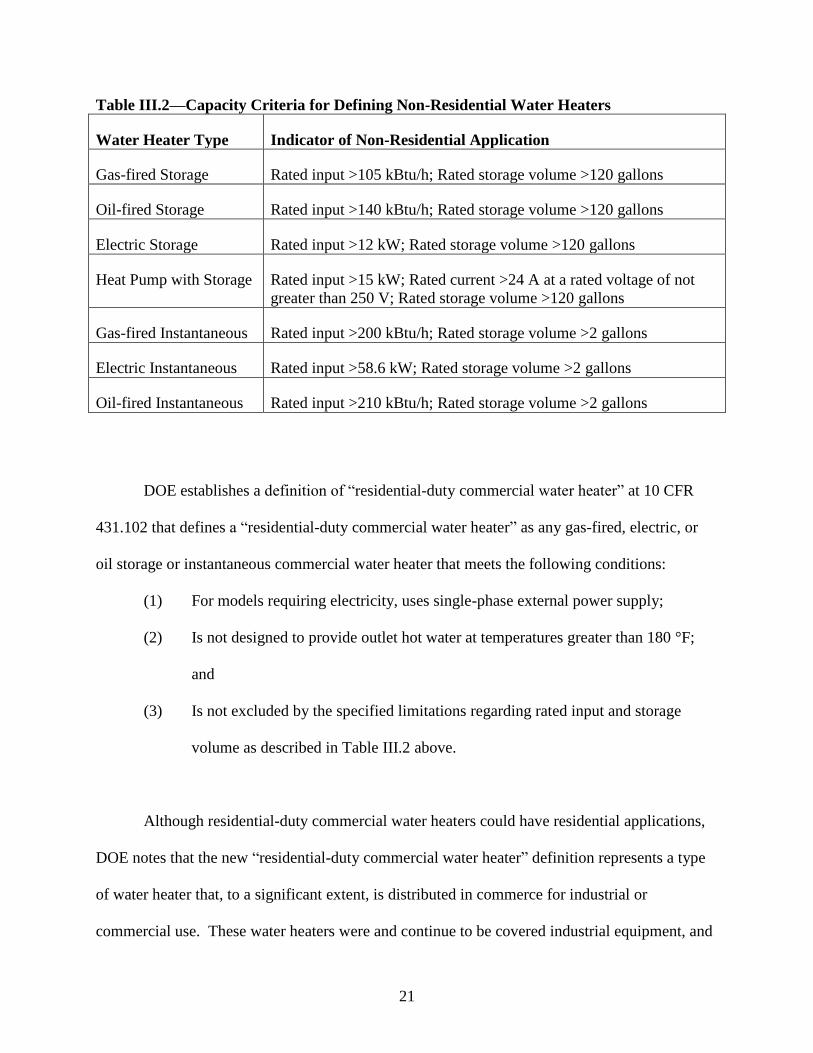
Table III.2—Capacity Criteria for Defining Non-Residential Water Heaters
Water Heater Type Indicator of Non-Residential Application
Gas-fired Storage Rated input >105 kBtu/h; Rated storage volume >120 gallons
Oil-fired Storage Rated input >140 kBtu/h; Rated storage volume >120 gallons
Electric Storage Rated input >12 kW; Rated storage volume >120 gallons
Heat Pump with Storage Rated input >15 kW; Rated current >24 A at a rated voltage of not
greater than 250 V; Rated storage volume >120 gallons
Gas-fired Instantaneous Rated input >200 kBtu/h; Rated storage volume >2 gallons
Electric Instantaneous Rated input >58.6 kW; Rated storage volume >2 gallons
Oil-fired Instantaneous Rated input >210 kBtu/h; Rated storage volume >2 gallons
DOE establishes a definition of “residential-duty commercial water heater” at 10 CFR
431.102 that defines a “residential-duty commercial water heater” as any gas-fired, electric, or
oil storage or instantaneous commercial water heater that meets the following conditions:
(1) For models requiring electricity, uses single-phase external power supply;
(2) Is not designed to provide outlet hot water at temperatures greater than 180 °F;
and
(3) Is not excluded by the specified limitations regarding rated input and storage
volume as described in Table III.2 above.
Although residential-duty commercial water heaters could have residential applications,
DOE notes that the new “residential-duty commercial water heater” definition represents a type
of water heater that, to a significant extent, is distributed in commerce for industrial or
commercial use. These water heaters were and continue to be covered industrial equipment, and
22
will continue to be subject to the applicable energy conservation standards in 10 CFR part 431
and the certification requirements for commercial and industrial equipment in 10 CFR part 429.
Similarly, although DOE recognizes that some consumer water heaters may be installed in a
commercial setting, those water heaters are covered consumer products for the purposes of DOE
regulations; the applicable energy conservation standards in 10 CFR part 430 continue to apply;
and they must be certified as consumer products under 10 CFR part 429.
If a commercial water heater does not meet all of the three conditions discussed above, it
would be classified as a commercial water heater that would not be expected to be used in
residential applications and would be subject to the current test methods prescribed in 10 CFR
431.106 and the certification requirements for commercial and industrial equipment in 10 CFR
part 429. If a commercial water heater meets all three criteria, DOE will consider it a
“residential-duty commercial water heater,” which would be subject to the uniform efficiency
descriptor and test method established in this final rule. Accordingly, DOE is adding a row to
Table 1 of 10 CFR 431.106 specifying 10 CFR part 430, subpart B, appendix E as the test
method for this type of equipment.
As stated in the November 2013 NOPR, DOE has determined that certain commercial
equipment, including unfired storage tanks, add-on heat pump water heaters, and hot water
supply boilers, are not appropriately rated using the uniform descriptor applicable to other water
heaters. 78 FR 66202, 66207 (Nov. 4, 2013). Unfired storage tanks are not complete water-
heating systems and require additional equipment in the field to operate. As such, their
performance as part of a complete water-heating system is dependent upon other components of
23
the system so that use of the uniform descriptor may be unrepresentative of its performance as
part of a complete water-heating system. In a similar vein, DOE previously determined that
residential add-on heat pump water heaters are not covered residential products. 75 FR 20112,
20127 (Apr. 16, 2010). DOE has authority to cover commercial add-on heat pumps; however,
this equipment does not have residential applications and, therefore, is not suitable for
application of the uniform efficiency descriptor. DOE also determined that hot water supply
boilers are more appropriately rated using the existing metrics for commercial water heaters, as
this equipment has very high input ratings and their use is similar to that of other commercial
water heaters in commercial applications. 78 FR 66202, 66207(Nov. 4, 2013). DOE will
address the types of commercial water-heating equipment that are excluded from the uniform
descriptor (e.g., unfired storage tanks, add-on heat pump water heaters, and hot water supply
boilers) in a subsequent test procedure rulemaking. DOE did not receive any comments
regarding the exclusion of unfired storage tanks, add-on heat pump water heaters, and hot water
supply boilers from coverage under the uniform descriptor.
2. Storage Capacity Limits
As noted above, under the existing regulatory definitions, DOE’s current residential
water heater test procedures are not applicable to gas or electric water heaters with storage tanks
that are at or above 2 gallons (7.6 L) and less than 20 gallons (76 L). The current DOE test
procedure for residential water heaters only applies to gas-fired water heaters with storage
volumes less than or equal to 100 gallons (380 L), electric resistance and heat pump storage
water heaters with storage volumes less than or equal to 120 gallons (450 L), and oil-fired water
24
heaters with storage volumes less than or equal to 50 gallons (190 L). 10 CFR part 430, subpart
B, appendix E, sections 1.12.1, 1.12.2, and 1.12.4.
The definitions in the current DOE test procedure specify that gas instantaneous water
heaters have a storage volume of less than two gallons (7.6 L) and that electric or gas storage-
type water heaters have a storage volume of 20 gallons (76 L) or more. The storage capacity of
oil water heaters in the test method is not restricted by a lower limit, with the specification
stating that an oil-fired storage water heater simply has a rated capacity less than or equal to 50
gallons (190 L). 10 CFR part 430, subpart B, appendix E, sections 1.7 and 1.12. The definitions
for “Electric Instantaneous Water Heater” and “Storage-type Water Heater of More than 2
Gallons (7.6 Liters) and Less than 20 Gallons (76 Liters)” are currently reserved. Id. at section
1.12.5.
In the 1998 rulemaking establishing test procedures for residential water heaters, DOE
proposed to include units with storage volumes between 2 and 20 gallons, but commenters raised
concerns that the test procedure demand of 64.3 gallons per day was not appropriate for these
small units. 63 FR 25996, 26000 (May 11, 1998). At that time, DOE concluded that the data
necessary to determine an appropriate representative daily hot water consumption for water
heaters with these storage volumes did not exist and that alternative procedures proposed by
commenters were not fully evaluated. For these reasons, the Department tabled consideration of
the inclusion of these water heaters until a future revision of the DOE test procedure.
25
As proposed in the November 2013 NOPR, DOE has decided to expand the scope of the
water heater test procedure for the uniform efficiency descriptor to include water heaters with
storage volumes between 2 and 20 gallons. 78 FR 66202, 66208 (Nov. 4, 2013). Rheem
supported the expansion of the scope to include units between 2 and 20 gallons, but asserted that
these products should not be covered by the current energy conservation standards. (Rheem, No.
69 at pp. 7-8) Bradford White requested clarification as to whether products between 2 and 20
gallons would be covered by the current energy conservation standards or test procedure only.
(Bradford White, No. 61 at p. 2) AHRI stated that, although DOE is developing a test method for
water heaters with storage volumes between 2 and 20 gallons, the current DOE minimum efficiency
standards for residential water heaters do not and should not apply to models having rated storage
volumes less than 20 gallons, and AHRI requested information regarding DOE activities with regard
to standards for these products. (AHRI, No. 80 at pp. 2-3)
The test procedure modifications for water heaters with a storage volume between 2 and
20 gallons specify the method of test set-up (including instrumenting such water heaters), a test
method to assess the delivery capacity, and the draw pattern to be used to determine the energy
efficiency of such units. The amendments for water heaters with storage volumes between 2 and
20 gallons are discussed in detail in section III.C of this final rule. Currently, there are no
minimum energy conservation standards applicable to water heater products with a storage
volume between 2 and 20 gallons, which will be the case until DOE conducts a rulemaking to
establish such standards. DOE clarifies this point in this final rule’s amendments to 10 CFR
430.32(d).
26
AEMTCA requires DOE to reconsider the scope of all water heater test procedures.
AEMTCA amended EPCA to require that the new uniform metric apply to the extent possible to
all water-heating technologies. (42 U.S.C. 6295(e)(5)(F) and (H))
In considering the upper limit to the storage capacity range, DOE is not aware of any
residential water heaters available on the market with storage volumes above 100 gallons, 120
gallons, and 50 gallons for gas-fired, electric (resistance and heat pump), and oil-fired water
heaters, respectively, that would be covered as residential products under EPCA. AHRI, A.O.
Smith, Giant, and Rheem supported the continued use of the current maximum storage capacity
limits. (AHRI, No. 75 at p. 2; A.O. Smith, No.62 at p.4; Giant, No.76 at p.2; Rheem, No.69 at
p.2)
In contrast, as AET stated in response to the January 2013 RFI, the ASME Boiler and
Pressure Vessel Code requires that vessels intended to store fluids under pressure must
individually undergo a rigorous test and inspection procedure if they have volumes greater than
120 gallons. AET noted that because these test and certification procedures are expensive,
manufacturers will avoid making products intended for residential use that require an ASME
inspection and code stamp. For this reason, AET commented that the upper limit of 120 gallons
would be appropriate for all residential water heaters. (AET, No. 22 at pp. 6–7)
DOE has reconsidered the water heater test procedure scope and expands the scope of the
test procedure to include all covered water heaters that could have residential applications and
adjusts the current limitations on maximum storage volume in the residential test procedure for
27
gas-fired, electric, and oil storage water heaters to 120 gallons for all three types. DOE
concludes that the amended test method adopted in today’s final rule adequately addresses water
heaters regardless of storage volume, provided that they meet the definition of a “residential
water heater” or a “residential-duty commercial water heater.” Consequently, DOE’s uniform
descriptor test procedure will apply to residential storage water heaters and “residential-duty
commercial water heaters” with storage volumes up to 120 gallons. As noted previously in
section III.A.1, DOE excludes non-residential (commercial) water heaters, and DOE agrees with
AET that a storage capacity limit of 120 gallons adequately separates residential and commercial
units of all water heater types.
3. Input Capacity Limits
AEMTCA requires that the new uniform efficiency descriptor apply to the maximum
extent practical to all water-heating technologies in use now or in the future. (42 U.S.C.
6295(e)(5)(H)) DOE’s current residential water heater test procedure is not applicable to gas-
fired instantaneous water heaters with input capacities at or below 50,000 Btu/h or at or above
200,000 Btu/h. 10 CFR part 430, subpart B, appendix E, section 1.7.2. In addition, the existing
test procedure is not applicable to gas-fired storage water heaters with input capacities above
75,000 Btu/h, electric storage water heaters with input ratings above 12 kW, and oil-fired storage
water heaters with input ratings above 105,000 Btu/h. 10 CFR part 430, subpart B, appendix E,
section 1.12.
In the November 2013 NOPR, DOE proposed to eliminate the minimum limit on the
firing rate of instantaneous gas water heaters of 50,000 Btu/h. 78 FR 66202, 66209 (Nov. 4,
28
2013). As discussed in section III.C, DOE adopts multiple draw patterns that vary based on the
delivery capacity of the water heater. Because the draw pattern is dependent upon delivery
capacity, gas-fired instantaneous units with a firing rate below 50,000 Btu/h can be tested under
the new procedure. Thus, DOE has concluded that there is no reason to retain this lower limit on
gas-fired instantaneous water heater delivery capacity. No comments were received opposing
this measure.
Similarly, DOE proposed to remove the maximum input ratings for gas-fired, electric,
and oil-fired storage water heaters and for gas-fired instantaneous water heaters from the test
procedure (although maximum input ratings specified in EPCA would still apply for the
purposes of equipment classification). Because draw patterns vary based on delivery capacity,
the new test procedure applies to models with input capacities above those included in the
current residential water heater test procedure. Although these maximum input limitations were
based upon EPCA’s “water heater” definition at 42 U.S.C. 6291(27), because the AEMTCA
amendments require that the new metric apply to all water-heating technologies except those that
do not have a residential use, DOE believes that such limits are no longer controlling or
appropriate in terms of the scope of the water heaters test procedure. DOE did not receive any
comments in response to the NOPR related specifically to the inclusion of input limitations on
residential products in the test procedure, but did receive comments regarding the application of
the test procedure to commercial models and suggesting input capacity limitations. Those
comments are discussed in section III.A.1. As discussed in section III.A.1, input rating
limitations are useful to distinguish water heaters without a residential use. Therefore, although
DOE will remove the input capacity limitations from the scope of the test method, DOE
29
establishes input capacity limits to define which units would qualify as “residential-duty”
commercial units and, thus, be required to be tested using the uniform descriptor test method.
These input capacity limitations are shown in Table III.2 above.
4. Electric Instantaneous Water Heaters, Gas-fired Heat Pump Water Heaters, and Oil-fired
Instantaneous Water Heaters
As discussed in the November 2013 NOPR, DOE’s test procedures do not contain a
definition for “electric instantaneous water heater,” but rather have a space reserved to define
that term (10 CFR part 430, subpart B, appendix E, section 1.7.1). 78 FR 66202, 66209 (Nov. 4,
2013). EPCA defines “electric instantaneous water heater” as containing no more than one
gallon of water per 4,000 Btu per hour of input and having an input capacity of 12 kilowatts
(kW) or less. (42 U.S.C. 6291(27)(B)) As noted in the November 2013 NOPR, the heating
power required for electric instantaneous water heaters intended for whole-home applications
typically is much higher than the power capability commonly found in storage-type electric
water heaters. 78 FR 66202, 66209 (Nov. 4, 2013). In the November 2013 NOPR, DOE
proposed to amend its water heater test procedure to include applicable provisions for electric
instantaneous water heaters, and to define the term “electric instantaneous water heater.” Id. at
66210.
AIM commented that DOE needs to be more inclusive of all types of water heaters when
defining the types of water heaters that will be covered by the uniform descriptor. (AIM No. 70
at p. 2)
30
DOE agrees in principle that all existing types of water heaters should be defined and,
thus, adopts definitions of “gas-fired heat pump water heater” and “oil-fired instantaneous water
heater,” in addition to a definition for “electric instantaneous water heater.” While not yet
commercially available, DOE is aware that manufacturers are currently developing gas-fired heat
pump water heaters and oil-fired instantaneous water heaters. Further, the new test procedure
applies to these types of water heaters. Accordingly, DOE adds definitions for these types of
water heaters at 10 CFR 430.2. (In addition, as proposed in the November 2013 NOPR, DOE is
moving all other definitions pertaining to defining the types of water heaters to 10 CFR 430.2.)
All three definitions reflect the definitions of these products as set forth in EPCA (42 U.S.C.
6291(27)) and are based on the current definitions for other types of water heaters. The
definition for “electric instantaneous water heater” has been altered slightly from the definition
proposed in the November 2013 NOPR to better align with the requirements of EPCA for these
products. These definitions read as follows:
Gas-fired Heat Pump Water Heater means a water heater that uses gas as the main
energy source, has a nameplate input rating of 75,000 Btu/h (79 MJ/h) or less, has a maximum
current rating of 24 amperes (including all auxiliary equipment such as fans, pumps, controls,
and, if on the same circuit, any resistive elements) at an input voltage of no greater than 250
volts, has a rated storage capacity of 120 gallons (450 liters) or less, and is designed to transfer
thermal energy from one temperature level to a higher temperature level to deliver water at a
thermostatically-controlled temperature less than or equal to 180°F (82°C).
31
Oil-fired Instantaneous Water Heater means a water heater that uses oil as the main
energy source, has a nameplate input rating of 210,000 Btu/h (220 MJ/h) or less, contains no
more than one gallon of water per 4,000 Btu per hour of input, and is designed to provide outlet
water at a controlled temperature less than or equal to 180°F (82°C). The unit may use a fixed or
variable burner input.
Electric Instantaneous Water Heater means a water heater that uses electricity as the
energy source, has a nameplate input rating of 12 kW (40,956 Btu/h) or less, contains no more
than one gallon of water per 4,000 Btu per hour of input, and is designed to provide outlet water
at a controlled temperature less than or equal to 180°F (82°C). The unit may use a fixed or
variable burner input.
DOE notes that the definition of “electric instantaneous water heater” being added to 10
CFR 430.2 encompasses only electric instantaneous water heaters that are residential (i.e., with
an input capacity of 12 kW or less). However, as discussed in section III.A.1, commercial (i.e.,
with an input capacity greater than 12 kW) electric instantaneous water heaters with input ratings
up to 58.6 kW are considered “residential-duty commercial water heaters,” and because water
heaters both above and below 12 kW have residential applications, both types would be covered
by the uniform efficiency descriptor.
In response to the November 2013 NOPR, Seisco and Thomas Harman commented that
12 kW is not an appropriate cutoff for electric instantaneous water heaters because there are
many electric instantaneous water heaters designed for and used in residences that have input
32
ratings above 12 kW. (Harman, No. 53 at p. 1; Seisco, No. 57 at pp. 10-11) In response, DOE
notes that the 12 kW limit is defined by EPCA and it is not at DOE’s discretion to change.
However, the 12 kW criteria will apply only insofar as determining the applicable minimum
energy conservation standard. As such, it remains the point above which electric instantaneous
models would be classified as “commercial” equipment for the basis of determining the
applicable energy conservation standards. Limits on the application of the uniform efficiency
descriptor pursuant to the new test procedure based on input and volume capacities are set forth
in Table III.2, above.
This final rule also provides for a maximum flow rate test for electric instantaneous water
heaters and a test to determine the energy efficiency expressed in terms of uniform energy factor
for these products. (As discussed in section III.B, the energy efficiency metric for water heaters
will be changed from “energy factor” to “uniform energy factor.”) These tests are identical to
those provided for gas-fired instantaneous water heaters.
B. Uniform Efficiency Descriptor Nomenclature
AEMTCA provided the following options for the uniform efficiency descriptor metric:
(1) a revised version of the energy factor descriptor currently in use; (2) the thermal efficiency
and standby loss descriptors currently in use; (3) a revised version of the thermal efficiency and
standby loss descriptors; (4) a hybrid of descriptors; or (5) a new approach. (42 U.S.C.
6295(e)(5)(G))
33
In the November 2013 NOPR, DOE proposed to use a revised version of the energy
factor as the uniform efficiency descriptor. 78 FR 66202, 66210 (Nov. 4, 2013). DOE received
no comments opposing the continued use of the energy factor metric in response to the
November 2013 NOPR. However, DOE received four comments (A.O. Smith, Bradford White,
EEI, Joint Comment) suggesting that the “energy factor” nomenclature be adjusted to distinguish
the old energy factor from the new. Additionally, the four commenters suggest that the new
“energy factor” nomenclature be differentiated by class (i.e., subscripts with the draw
classification). (A.O. Smith No. 62 at p. 3; Bradford White No. 61 at p. 6; EEI No. 63 at p. 4;
Joint Comment No. 77 at p. 2) NEEA and NPCC commented that the “energy factor”
nomenclature as it currently stands is appropriate and that changes to the test procedure are not
significant enough to warrant a new descriptor. (NEEA and NPCC No. 64 at p. 1) NEEA and
NPCC and the Joint Comment stated that the new “energy factor” nomenclature should not be
distinguished by fuel type or technology group. (NEEA and NPCC No. 64 at p. 16; Joint
Comment No. 77 at p. 2)
DOE agrees with commenters that confusion could occur if the name of the metric
remains unchanged between the current and amended test procedures. Because the existing and
new ratings are determined under different test conditions, which can result in a different rating,
DOE believes it is necessary to adopt a new name to distinguish between the efficiency result
under the existing test procedure and the result under the amended test procedure. As a result,
DOE adopts a “uniform energy factor,” to be denoted as “UEF” in the test procedure, as
distinguished from the “Ef” rating determined under the current test procedure.

34
C. Draw Pattern
The term "draw pattern" describes the number, flow rate, length, and timing of hot water
removal from the water heater during testing. Primary decisions in developing draw patterns
include the total amount of water to be removed during the test and the number of draws during
the test. The total amount of water taken in each draw, which is a function of the flow rate and
the length of the draw, must also be specified. Finally, the spacing between those draws is
needed to complete the specification of the draw pattern.
DOE proposed to modify the draw pattern that is used in the existing test procedure in the
November 2013 NOPR. 78 FR 66202, 66210-17 (Nov. 4, 2013). Under DOE’s proposal, the
single draw pattern that is currently applied during the 24-hour simulated use test would be
replaced with one of four patterns that is more representative of the demand put on a water heater
of different delivery capacity. These four draw patterns were termed “point-of-use,” “low
usage,” “medium usage,” and “high usage.” The selection of the draw pattern to be used in the
simulated-use test would be based upon the results of the first-hour rating test or the maximum
GPM (gallons per minute) rating test.
DOE received seven comments in general support of the move to four different draw
patterns. (HTP No. 59 at p. 2; A.O. Smith No. 62 at p. 2; EEI No. 63 at p. 4; NEEA and NPCC
No. 64 at p. 3; AHRI No. 75 at p. 3; Giant No. 76 at p. 3; Joint Comment No. 77 at p. 6) HTP
recommended that DOE consider altering the total water drawn in the medium-usage pattern to
64.8 gallons to assist in correlating between current metrics and the proposed metrics. NEEA
and NPCC indicated a slight preference for draw patterns proposed as part of the deliberations
35
for ASHRAE 118.2, “Method of Testing for Rating Residential Water Heaters,” because those
draws are more consistent with the daily hot water use found in their field data. AHRI indicated
that the proposed draw patterns were appropriate but that it preferred the draw patterns submitted
in its comment to the January 2013 RFI. (AHRI No. 46 at p. 5)
DOE received one comment that supported the move to multiple draw patterns but that
recommended five draw patterns instead of four and provided alternative bases for developing
the patterns. (AET No. 58 at p. 3) AET commented that the proposed draw patterns could result
in water being delivered during the simulated-use test that may be considered to be too cold for
typical uses and recommended that a fifth category termed “Sink” be created that would apply to
the smallest water heaters. AET discussed how the amount of water that can be withdrawn in a
continuous draw can be estimated from the first-hour rating and stated that the maximum draw
volumes imposed in the proposed draw patterns may yield an “invalid test.” Particular emphasis
was placed on the point-of-use category, in which a 2-gallon water heater would be expected to
deliver a 2-gallon draw. Another concern expressed by AET is that water heaters with the same
storage volume but with slightly different input rates would be tested according to different draw
patterns. AET suggested that selection of the draw pattern used for the simulated-use test should
be based on two factors: the measured storage volume and the first-hour rating. AET
recommended the largest draw volume that should be implemented in each draw pattern to meet
the capabilities of the water heaters in that category. AET estimated that the first draw delivery
capability of a storage water heater is 0.95*0.85*(Rated Storage Volume), where 0.95 represents
the currently allowed tolerance on storage volume and 0.85 accounts for mixing of hot and cold
water during draws. Id.
36
DOE received three comments from AET, SMT, and Bradford White related to the
details in the proposed test procedure of determining the standby loss coefficient, “UA,” which is
used to adjust the daily energy consumption to account for deviations from nominal conditions.
AET expressed concern that, with water heaters having very slow recoveries, the test could result
in a water heater with drastically different stored water temperature at the start of the test than at
the end, thereby necessitating a major correction to the energy consumed. AET recommended
extending the test beyond 24 hours for such water heaters, ending the test only after a recovery
occurs. Energy consumption during the test would be modified to normalize to a 24-hour time
period by removing the estimated standby loss during the time exceeding 24 hours. AET
commented that it is much more accurate to normalize to a common time period than it is to end
the test prior to a recovery occurring. AET stated that this approach would ensure that a
recovery occurs during the period of the test when the UA value is determined and that it would
result in an average tank temperature that changes less from the start of the test to the end of the
test. (AET No. 58 at p. 1). SMT expressed concern that large-capacity models may not initiate
recovery during the first draw cluster of tests or may initiate a recovery during a standby portion
of the test. In these cases, SMT commented that determination of the UA may not be possible.
SMT suggested that the test should start with a fully-charged water heater and that the first draw
cluster should start eight hours after this point. According to SMT, the UA value would be
determined during this eight-hour period. (SMT No. 66 at p. 2). Bradford White commented
that the new test procedure can take standby loss readings when the water heater is recovering
and/or when water is being drawn, which would lead to inaccurate measures of standby loss.
(Bradford White No. 61 at p. 8).
37
After consideration of these comments, DOE has decided to adopt the modifications to
the draw patterns as originally proposed in the November 2013 NOPR. DOE has reviewed the
total amount of water drawn per day in each draw pattern and has observed that those values
match well with field data collated by the Lawrence Berkeley National Laboratory.10
DOE
acknowledges that a medium-use draw pattern having the same daily draw volume as that
prescribed in the current test procedure would remove some uncertainty in converting from the
existing efficiency metric to the new uniform metric since the total daily draw volume would not
impact the rating. However, DOE has decided to maintain a lower daily draw volume in the
new draw schedule to better match field data available for a medium-usage situation.
DOE considered adding a fifth draw pattern as recommended by AET, but a review of
data from testing of low-volume water heaters indicate that the efficiency can be accurately
determined using the four proposed draw patterns. While delivery temperatures did drop below
120°F during some draws of these tests, DOE has concluded that the efficiency is still accurately
determined using this test procedure and that the added complexity of an additional draw pattern
is not warranted.
DOE will continue to use the first-hour rating to assign a draw pattern for use during the
simulated-use test. DOE examined using a combination of first-hour rating and storage volume
to categorize the water heater for assigning a draw pattern, as suggested by AET, but is
concerned that some water heaters may not fit into any category because their storage volumes
10
Lutz, JD, Renaldi, Lekov A, Qin Y, and Melody M., “Hot Water Draw Patterns in Single Family Houses:
Findings from Field Studies,” Lawrence Berkeley National Laboratory Report number LBNL-4830E (May 2011)
(Available at http://www.escholarship.org/uc/item/2k24v1kj) (last accessed June 17, 2014).
38
would correspond to one draw pattern while their first-hour ratings would correspond to a
different one. Additionally, as noted above, AET estimates that the first draw delivery capability
of a storage water heater is 0.95*0.85*(Rated Storage Volume), which accounts for the tolerance
currently afforded manufacturers on storage volume and the effect of mixing of hot and cold
water within the storage water heater during draws. DOE agrees that this method for estimating
first draw delivery capacity is appropriate for conventional electric storage water heaters.
However, the Department is concerned that the effect of mixing hot and cold water within the
unit during draws is not well understood for the emerging water-heating technologies that are
noted by the commenter. Therefore, basing the categorization of water heaters into usage bins
(i.e., very small, low, medium, and high) to determine the appropriate draw pattern based on this
uncertain number is likely to lead to miscategorization for some water heaters. In the end, DOE
has decided that the first-hour rating is the best metric available for determining water heater size
classification for purposes of efficiency testing.
DOE is adopting the draw volumes proposed in the November 2013 NOPR. Test
results11
indicate that the draw volumes incorporated into the proposed patterns, while resulting
in delivery temperatures that may not match the nominal outlet temperatures, provide a
sufficiently accurate estimate of the energy efficiency and that these draw patterns will result in
an accurate estimate of the efficiency of water heaters within each size classification. The flow
rates and volumes specified in the November 2013 NOPR represent the best alternative for
characterizing water heaters at both the lower and upper limits of a size category.
11
Test results from DOE testing for the NOPR are summarized in the November 2013 Water Heater Test Procedure
Rulemaking Development Testing Preliminary Report, available in the rulemaking docket at:
http://www.regulations.gov/#!documentDetail;D=EERE-2011-BT-TP-0042-0052

39
In response to the comment from Bradford White stating concern that the standby loss
coefficient (UA) can be determined while a recovery is occurring, DOE notes that there is a
possibility of a recovery taking place during the portion of the test when data are collected to
determine UA, just as there is the possibility in the current test method. The determination of
UA, however, may require a reheat to maintain the stored water temperature to obtain a valid
estimate of UA. As for the standby time period during which energy loss to the ambient is
corrected, DOE notes that time when draws are taking place are omitted from the calculation.
See section 6.3.5 of appendix E as adopted in this final rule. Therefore, DOE is making no
changes in response to the comment.
DOE considered amending the timing of the simulated-use test, as suggested by some
commenters, to improve the determination of UA. DOE examined data from a range of
simulated-use tests and decided that the test procedure requires modification to improve the
determination of UA for some special cases.
The first modification responds to concerns expressed about the determination of UA for
water heaters with low recovery rates. DOE observed that the first recovery may not begin until
several hours into the designated standby period and could extend into the second draw cluster.
DOE examined data from tests on such water heaters and modified the test procedure provisions
for determining UA in the event that a recovery does not begin during the first draw cluster.
As proposed in the November 2013 NOPR, the standby period for determination of UA
was intended to occupy the majority of the period between the end of the first draw cluster and
40
the start of the second draw cluster. 78 FR 66202, 66217, 66236 (Nov. 4, 2013). However,
because the standby period is supposed to start at the end of the first recovery under the proposed
procedure, the standby period may not start until well into the 24-hour test for water heaters with
a very slow recovery rate. For one tested water heater, DOE observed that the first recovery did
not begin until several hours past the end of the first draw cluster and ended after subsequent
draws occurred during the test. Under the proposed test procedure, the standby period started at
the end of this first recovery period and continued until the next draw started. This procedure
could result in a very short time period for determination of UA, which might lead to erroneous
results.
To address this issue, DOE amends the proposed test procedure by starting the standby
period five minutes following the last draw of the first draw cluster if a recovery is not occurring,
as opposed to waiting until after the first recovery period ends. The end point of the standby
period will remain as proposed in the November 2013 NOPR. This change ensures an accurate
determination of UA for all units, including those with low recovery rates and those that delay
onset of heating until after the first cluster of draws.
The second clarification addresses water heaters that undergo a recovery that begins at
the end of the first draw cluster and continues over the entire standby period between the first
and second draw clusters. In these instances, the standby period continues past the end of the 24-
hour test. To address this issue, DOE amends the test procedure to initiate the standby period at
the end of the first recovery following the final draw and to continue measurements for eight
hours from that point.
41
DOE concludes that the approaches implemented in the final rule will determine a
standby loss coefficient that accurately adjusts the daily energy consumption when the ambient
temperature deviates from the nominal value during testing. The Department is adopting this
approach, as opposed to the one presented by AET, in order to maintain a test duration of 24
hours for nearly all water heaters while providing accurate representation of the water heater’s
energy efficiency.
DOE received one comment requesting a change in the name of the “point-of-use” draw
pattern, stating that the term “point-of-use” describes the installed location of a water heater as
opposed to the delivery capacity, which is the characteristic described by the other three category
names (i.e., “low,” “medium,” and “high”). (AIM No. 71 at p. 1) AIM suggested a name of
“very small” for this category. DOE agrees in principle with this comment and has decided to
change the name of the “point-of-use” category to “very-small-usage.”
Bradford White commented that the tolerances of +/- 0.25 gallons for the volume
removed in each draw in the proposed test procedure could lead to large discrepancies in the
overall volume removed, which could in turn necessitate a test laboratory to skip a final draw to
achieve the overall tolerance of +/- 1 gallon for the daily water delivery. (Bradford White No. 61
at pp. 8-9) DOE agrees with this observation and is tightening the tolerances on some draws in
the final rule. For draws taken at a nominal flow rate of 1.7 GPM or less, DOE is requiring that
those draws have a tolerance of +/- 0.1 gallons. With the data acquisition rate during draws set
to 3 seconds, DOE believes that this level of tolerance is achievable. At the nominal flow rate of

42
3 GPM, however, the frequency of data collection may not allow for such tight control of draw
volumes during each draw, so DOE is maintaining the tolerance of +/- 0.25 GPM for those
draws. DOE is already increasing the frequency of data collection and does not believe it is
necessary to increase it further to allow for a stricter tolerance on 3 GPM draws. DOE notes that
only the high-usage pattern contains draws with a flow rate of 3 GPM, and only 3 of the 14
draws are at that flow rate. As a result, DOE expects that the overall tolerance of +/- 1 gallon for
the daily water delivery can be achieved because the tighter tolerance applies to the remaining 11
draws.
DOE acknowledges that, given the tolerances on individual draws, a situation may arise
whereby the volume of the final draw would need to be adjusted downward so much that a draw
volume of zero may be required to meet the overall tolerance on the daily draw volume. DOE
concludes that this scenario would result in an invalid test and has inserted a statement in the test
procedure indicating that “if this adjustment to the volume drawn in the last draw results in no
draw taking place, the test is considered invalid.” Table III.3 through Table III.6 show the draw
patterns that DOE is adopting.
Table III.3 Very-Small-Usage Draw Pattern
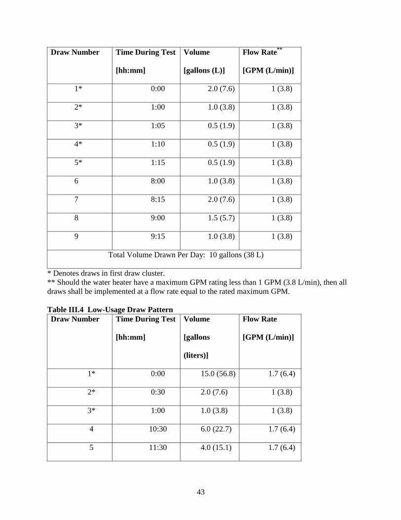
43
Draw Number Time During Test
[hh:mm]
Volume
[gallons (L)]
Flow Rate**
[GPM (L/min)]
1* 0:00 2.0 (7.6) 1 (3.8)
2* 1:00 1.0 (3.8) 1 (3.8)
3* 1:05 0.5 (1.9) 1 (3.8)
4* 1:10 0.5 (1.9) 1 (3.8)
5* 1:15 0.5 (1.9) 1 (3.8)
6 8:00 1.0 (3.8) 1 (3.8)
7 8:15 2.0 (7.6) 1 (3.8)
8 9:00 1.5 (5.7) 1 (3.8)
9 9:15 1.0 (3.8) 1 (3.8)
Total Volume Drawn Per Day: 10 gallons (38 L)
* Denotes draws in first draw cluster.
** Should the water heater have a maximum GPM rating less than 1 GPM (3.8 L/min), then all
draws shall be implemented at a flow rate equal to the rated maximum GPM.
Table III.4 Low-Usage Draw Pattern
Draw Number Time During Test
[hh:mm]
Volume
[gallons
(liters)]
Flow Rate
[GPM (L/min)]
1* 0:00 15.0 (56.8) 1.7 (6.4)
2* 0:30 2.0 (7.6) 1 (3.8)
3* 1:00 1.0 (3.8) 1 (3.8)
4 10:30 6.0 (22.7) 1.7 (6.4)
5 11:30 4.0 (15.1) 1.7 (6.4)
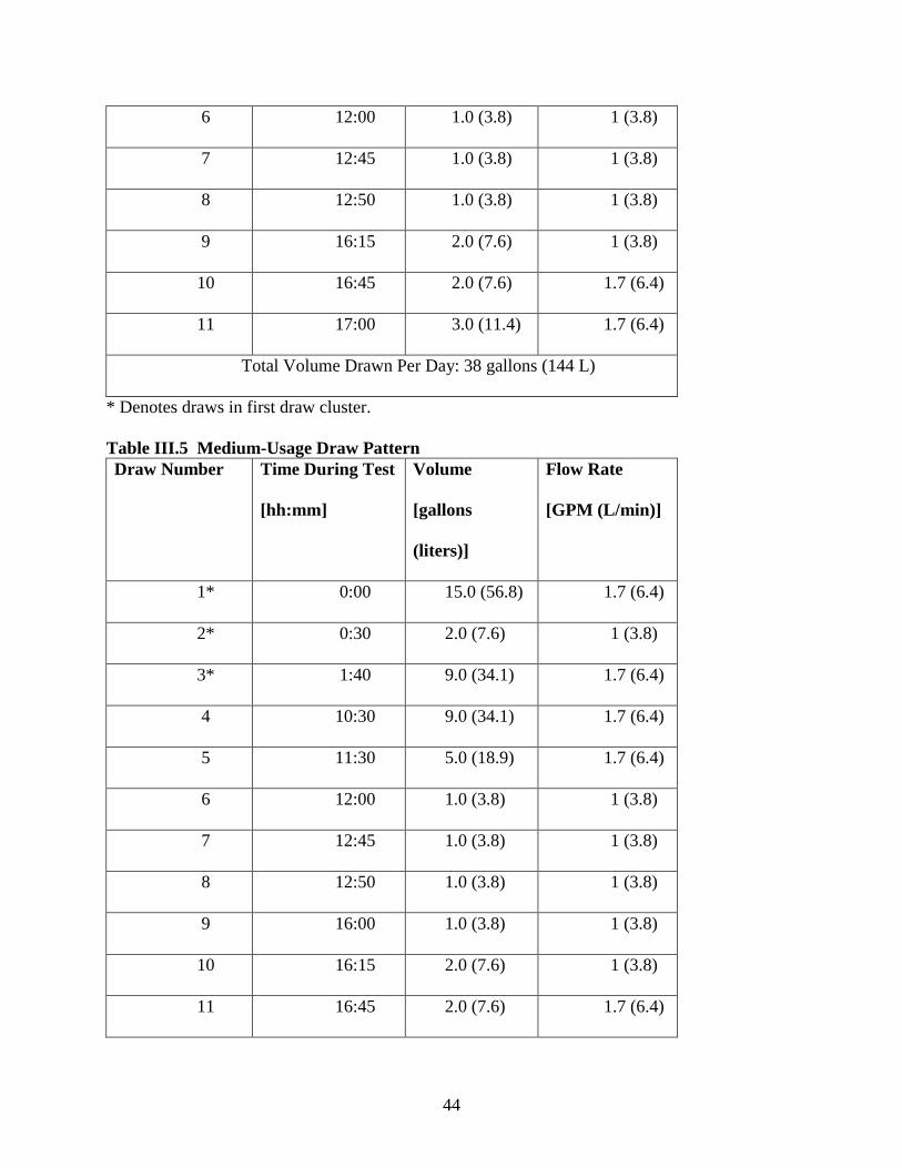
44
6 12:00 1.0 (3.8) 1 (3.8)
7 12:45 1.0 (3.8) 1 (3.8)
8 12:50 1.0 (3.8) 1 (3.8)
9 16:15 2.0 (7.6) 1 (3.8)
10 16:45 2.0 (7.6) 1.7 (6.4)
11 17:00 3.0 (11.4) 1.7 (6.4)
Total Volume Drawn Per Day: 38 gallons (144 L)
* Denotes draws in first draw cluster.
Table III.5 Medium-Usage Draw Pattern
Draw Number Time During Test
[hh:mm]
Volume
[gallons
(liters)]
Flow Rate
[GPM (L/min)]
1* 0:00 15.0 (56.8) 1.7 (6.4)
2* 0:30 2.0 (7.6) 1 (3.8)
3* 1:40 9.0 (34.1) 1.7 (6.4)
4 10:30 9.0 (34.1) 1.7 (6.4)
5 11:30 5.0 (18.9) 1.7 (6.4)
6 12:00 1.0 (3.8) 1 (3.8)
7 12:45 1.0 (3.8) 1 (3.8)
8 12:50 1.0 (3.8) 1 (3.8)
9 16:00 1.0 (3.8) 1 (3.8)
10 16:15 2.0 (7.6) 1 (3.8)
11 16:45 2.0 (7.6) 1.7 (6.4)
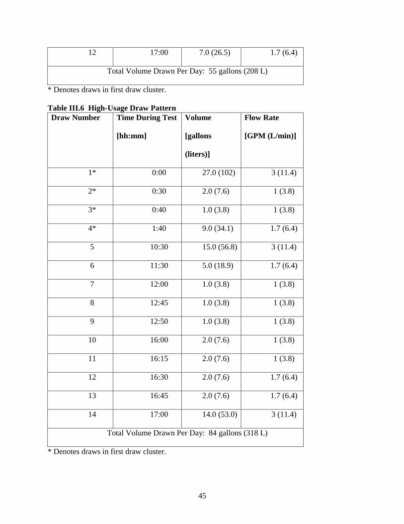
45
12 17:00 7.0 (26.5) 1.7 (6.4)
Total Volume Drawn Per Day: 55 gallons (208 L)
* Denotes draws in first draw cluster.
Table III.6 High-Usage Draw Pattern
Draw Number Time During Test
[hh:mm]
Volume
[gallons
(liters)]
Flow Rate
[GPM (L/min)]
1* 0:00 27.0 (102) 3 (11.4)
2* 0:30 2.0 (7.6) 1 (3.8)
3* 0:40 1.0 (3.8) 1 (3.8)
4* 1:40 9.0 (34.1) 1.7 (6.4)
5 10:30 15.0 (56.8) 3 (11.4)
6 11:30 5.0 (18.9) 1.7 (6.4)
7 12:00 1.0 (3.8) 1 (3.8)
8 12:45 1.0 (3.8) 1 (3.8)
9 12:50 1.0 (3.8) 1 (3.8)
10 16:00 2.0 (7.6) 1 (3.8)
11 16:15 2.0 (7.6) 1 (3.8)
12 16:30 2.0 (7.6) 1.7 (6.4)
13 16:45 2.0 (7.6) 1.7 (6.4)
14 17:00 14.0 (53.0) 3 (11.4)
Total Volume Drawn Per Day: 84 gallons (318 L)
* Denotes draws in first draw cluster.
46
D. Instrumentation
In the November 2013 NOPR, DOE proposed to maintain the instrumentation installation
requirements and piping configuration as currently specified in the residential water heater test
procedure. 78 FR 66202, 66217 (Nov. 4, 2013). For storage water heaters having a rated
volume below 20 gallons, which are not covered in the existing DOE test method, DOE
proposed that the average tank temperature be determined based on three temperature sensors
located at the vertical midpoints of three sections of equal volume within the storage tank, as
opposed to the currently required six sensors for storage water heaters having a rated volume
above 20 gallons. Id. No comments were received opposing this approach, but AET requested
that guidance should be provided regarding the unspecified horizontal lengths of pipe in the
figures. (AET No. 58 at p. 20) For the final rule, DOE has modified Figures 1 through 4 of the
test procedure to include those dimensions.
DOE proposed in the November 2013 NOPR to tighten the allowed accuracy on electric
power and energy measuring equipment from the current value of ±1 percent to ±0.5 percent. 78
FR 66202, 66217 (Nov. 4, 2013). A study has shown the significant effect of the accuracy of the
electric power measurements on the uncertainty in the overall energy factor.12
A similar change
was made in ASHRAE 118.2– 2006, “Method of Testing for Rating Residential Water Heaters,”
and DOE research confirms that equipment having this tolerance level is readily available. DOE
also proposed in the November 2013 NOPR that, for mass measurements greater than or equal to
10 pounds (4.5 kg), a scale that is accurate within ±0.5 percent of the reading must be used to
make the measurement. Id. Lastly, DOE proposed that, for relative humidity measurements, a
12
Healy WM, Lutz JD, and Lekov AB., “Variability in Energy Factor Test Results for Residential Electric Water
Heaters,” HVAC&R Research, Vol. 9, No. 4 (October 2003).
47
sensor that is accurate within ±1.5 percent of the reading be used to make the measurement. Id.
at 66220. No comments were received opposing these proposals, so DOE has incorporated these
proposals into the final rule.
DOE also proposed in the November 2013 NOPR to modify the data acquisition rate of
the inlet and outlet water temperature during draws. Id. at 66217. Currently, for all water
heaters except variable firing rate instantaneous water heaters, measurements of the inlet and
outlet water temperature are taken at 5-second intervals starting 15 seconds after the draw
commences. For instantaneous water heaters with a variable firing rate, inlet and outlet water
temperature measurements are taken at 5-second intervals starting 5 seconds after the draw
commences. The test procedure amendments call for temperature data at the inlet and outlet
temperature sensors to be recorded at 3-second intervals starting 5 seconds after commencement
of the draw for all water heaters. Accordingly, DOE also proposed that the time constant of the
instruments used to measure the inlet and outlet water temperatures be no greater than 2 seconds.
DOE anticipates that this approach will better capture the energy impact of water heater startup
and cycling. Id. at 66217. No comments were received opposing these measures, so DOE has
incorporated these proposals into the final rule.
E. Test Conditions
1. Outlet Water Temperature
The current residential water heater test procedure calls for the temperature of the tank to
be set so that the average hot water temperature within the storage tank is at 135°F ± 5°F (57.2°C
± 2.8°C). 10 CFR part 430, subpart B, appendix E, section 2.4. The set point impacts the
48
performance of various types of water heaters differently, so DOE reexamined in the proposed
test procedure the set point specification and how it is determined. In the November 2013
NOPR, DOE proposed to use a measurement of the temperature of the delivered water, rather
than mean tank temperature, for setting the temperature for storage-type water heaters, and also
proposed that the set point temperature of all residential water heaters be reduced to 125°F +/-
5°F (51.7 °C +/- 2.8 °C). 78 FR 66202, 66219-20 (Nov. 4, 2013). This value was primarily
selected based on data available in DOE’s analysis for the April 2010 energy conservation
standards final rule, which found that the average set point temperature for residential water
heaters in the field is 124.2°F (51.2°C). Additionally, the recent compilation of field data across
the United States and southern Ontario by LBNL (referenced above) found a median daily outlet
water temperature of 122.7°F (50.4°C), which supports specifying a test set point temperature of
125°F. DOE proposed that this new value would apply to first-hour rating tests for storage water
heaters, maximum flow rate tests for instantaneous water heaters, and energy factor tests for all
water heaters. DOE also tentatively concluded that a set point of 125°F in the test method would
not result in safety concerns related to the growth of Legionella. Further, DOE noted that water
heaters are commonly set to temperatures in the range of 120°F to 125°F even though the current
set point in the test method is 135°F. 78 FR 66202, 66219 (Nov. 4, 2013).
DOE received five comments (AET, EEI, HTP, NEEA and NPCC, Joint Comment) in
response to DOE’s outlet water temperature proposals in the November 2013 NOPR supporting
the switch to a set point temperature of 125 °F for the first-hour rating and maximum flow rate
tests and the 24-hour simulated-use test. (AET, No. 58 at p. 5; EEI, No. 63 at p. 5; HTP, No. 59
at pp. 1-3; NEEA and NPCC, No. 64 at p. 9; Joint Comment, No. 77 at pp. 6-7) Advocates for
49
the 125 °F outlet water temperature argue that it is the most representative of actual use in the
field and, thus, should be used to determine performance under representative conditions.
Additionally, AET and HTP suggested that specifying an outlet water temperature, as opposed to
a stored water temperature, is more appropriate for evaluating water heaters using certain
controls that purposely keep the stored water temperature at a low value. (AET No. 58 at p. 1;
HTP, No. 59 at p. 3) DOE received five comments (AIM, AHRI, A.O. Smith, GE, and Giant) in
favor of keeping the set point temperature at 135 °F for the first-hour rating test or increasing it
for both the first-hour rating/maximum flow rate test and the 24-hour simulated-use test. (AIM,
No. 72 at p. 3; AHRI, No. 75 at pp. 3-4; A.O. Smith, No. 62 at p. 2; GE, No. 78 at p. 1; Giant,
No. 76 at pp. 2-3) Four of the commenters who opposed the decrease in set point (AHRI, A.O.
Smith, GE, Giant) argue that the burden of reestablishing the draw pattern bin categories using
first-hour rating and maximum GPM values under the lower set point is too great because the
change in first-hour ratings will add additional uncertainty to the establishment of the bins. AIM
argued that the set point temperature should be increased because when the temperature is
decreased in the field, the water heater will see a boost in energy efficiency. Rheem
acknowledged that many water heaters are operated at lower temperatures than the set point
specified in the current DOE test procedure and suggested that the 24-hour simulated-use test
and associated draws would be more representative at the 125 °F set point temperature.
However, based on test data, Rheem argued that the changes to the first-hour rating values from
the change in set point are too unpredictable to serve as a basis for determining the draw pattern
bin categories and suggested that the first-hour rating test should continue to be performed at 135
°F, as is current practice. (Rheem, No. 69 at pp. 3, 5)
50
DOE has carefully considered these comments and concludes that a delivered water
temperature of 125 °F will be applied to first-hour rating tests for storage water heaters,
maximum flow rate tests for flow-activated water heaters, and energy factor tests for all water
heaters. DOE is required to establish test procedures that are representative of how a covered
product would be used in the field, and based on the data discussed previously, DOE concludes
that 125 °F is the most representative temperature for the United States market. DOE has
determined that the test should be conducted at a typical operating temperature and should not
penalize those units optimized for such typical conditions. Moreover, DOE has determined that
conducting the simulated-use test at a different temperature from the delivery capacity tests
would add an undue burden on manufacturers and would result in ratings that would not be
representative of typical usage in the field. While maintaining the test temperature at the value
currently used in the test procedure could eliminate one source of uncertainty in converting
existing energy factors to new uniform energy factors, DOE has determined that this conversion
is feasible and that the benefits of testing at a representative temperature outweigh the short-term
challenges in converting existing ratings.
In response to the concerns expressed by AHRI, A.O. Smith, GE, and Giant regarding
uncertainties in converting first-hour ratings values obtained at 135 °F to comparable values at
125 °F, DOE revisited the values that were used to place water heaters into bins for uniform
energy factor testing. In the November 2013 NOPR, DOE based these breakpoint values on
information present in the current plumbing code that indicate appropriate water heaters for
various home configurations based on their first hour rating values obtained under the existing
test procedure. 78 FR 66202, 66214 (Nov. 4, 2013). Preliminary testing by DOE indicated that
51
the first-hour ratings obtained under the new procedure were comparable to those obtained under
the existing test procedure, so DOE proposed to maintain the breakpoints between bins despite
the change in the conditions for the first-hour rating test.
DOE requested data to demonstrate the effect of modifying the first-hour rating test
conditions and received data from Rheem and Bradford White. (Rheem No. 69 at p. 3; Bradford
White No. 61 at p. 8) Rheem presented actual first-hour rating values under both the current test
and the proposed test, whereas Bradford White simply provided the percentage change in the
first-hour rating between the two test procedures. Both data sets suggest an overall downward
trend of first-hour rating under the proposed test procedure but that there is variability in the
results. Based on these data and additional data collected by DOE, the Department concludes
that numerous characteristics of a water heater affect the change in its first-hour rating obtained
at 135 °F, as compared to that obtained at 125 °F. The uncertainty in how the ratings change,
however, does not justify abandoning the 125 °F test temperature. Since DOE has determined
that the most representative delivery temperature is 125 °F and no comments were received that
refuted the method applied to obtain the first-hour rating at that temperature, DOE concludes that
the first-hour rating test, as proposed, provides an appropriate measure of the delivery capacity of
a water heater as would be observed in the field.
DOE maintains that the breakpoint values used to place water heaters into bins for
uniform energy factor testing presented in the NOPR are appropriate for tests conducted at 135
°F, but acknowledges that some adjustments may be needed for tests conducted at 125 °F since
first-hour rating values may change at this temperature. To better account for the change in the
52
first-hour rating procedure, DOE used the expanded set of available experimental data to reassess
the proposed breakpoint values of first-hour ratings for placing water heaters into sizing bins for
the simulated-use test. DOE examined different regressions using the data submitted by Rheem
and those collected by the Department and found that the ratings at 125 °F and those at 135 °F
could be modeled as functions of storage volume and the product of input rate and recovery
efficiency. The recovery efficiency for data presented by Rheem was estimated based on the
description of the water heater being tested. These regressions were then used to determine what
breakpoint values would result in nearly the same classification for a particular water heater
tested at 125 °F as it would have when tested at 135 °F, based on its storage volume, recovery
efficiency, and input rate. Based on this analysis, DOE decreased the breakpoint values for each
size classification for testing at 125 °F under the new test procedure, as compared to the
breakpoint values proposed in the NOPR.13
The new limits of first-hour ratings (FHR) for each
category are as follows:
Very Small: FHR < 18 gallons
Low: 18 <= FHR < 51 gallons
Medium: 51 <= FHR < 75 gallons
High: FHR >= 75 gallons
For the first-hour rating test, DOE proposed in the November 2013 NOPR that draws
would terminate when the outlet temperature drops 15°F (8.3°C) from its maximum outlet
temperature during the draw, as opposed to the drop of 25°F (13.9°C) implemented in the current
13
In the November 2013 NOPR, DOE proposed the following breakpoints for each size classification for testing at
125°F. Point-of-use (since renamed “very small”): < 20 gallons; low: 20 <= FHR < 55 gallons; medium: 55 <=
FHR < 80 gallons; and high: >= 80 gallons. 78 FR 66202, 66235 (Nov. 4, 2013).
53
test procedure. This change would ensure that water delivered meets the nominal useful
temperature of 110°F (43.3°C). AET and AIM supported this proposal. (AET, No. 58 at p. 6;
AIM, No. 72 at p. 1) AET suggested that water delivered at a temperature lower than the
minimum useful temperature of 110 °F should not be counted in the first-hour rating test. AIM
suggested that useful hot water delivered be measured separately from total water delivered.
AET and AIM also suggested that water delivered below 110 °F should not be counted as useful
delivered hot water in the 24-hour simulated use test. (AET No. 58 at p. 7; AIM No. 72 at p.1)
DOE concludes that the lower temperature limit of useful hot water at 110 °F is
appropriate for the first-hour rating test and establishes that draws during the test will terminate
when the delivery temperature drops to 15 °F below the outlet water temperature (which is
nominally 125 °F), resulting in a draw termination temperature of approximately 110 °F for
draws during the first-hour test. For the simulated-use test, however, DOE does not restrict
outlet water temperature to at or above 110 °F. While it strongly considered the comments made
by AET and AIM in this regard, in DOE’s view, the simulated-use test, which provides a
measure of energy efficiency rather than delivery capability, is best conducted without regard to
water outlet temperature. A standard cutoff temperature of 110 °F is necessary for the first-hour
rating test in order to determine the appropriate draw pattern, but no minimum temperature is
necessary to estimate energy efficiency. Although DOE has selected its draw patterns to ensure
that a water heater can deliver hot water during all draws, DOE recognizes that there may be
cases where water heaters on the lower end of the capacity limit in each bin deliver water at a
lower temperature than a consumer might desire. In these cases, DOE believes that accounting
for water delivered at temperatures below 110 °F would be representative of water heater energy

54
performance in the field. DOE uses correction factors in the test procedure’s calculation routines
to adjust the daily energy consumption to estimate energy consumption at a nominal outlet
temperature of 125 °F since daily energy consumption will differ based on the outlet temperature
of the water provided.
As noted above, in addition to proposing to change the temperature setting at which the
test occurs, DOE also proposed in the November 2013 NOPR to change the methodology for
setting the temperature of storage-type units to rely on outlet water temperature rather than mean
tank temperature. For water heaters with a single thermostat, DOE proposed to specify a set
point based on the outlet water temperature during a draw. For water heaters with multiple
thermostats, DOE proposed to maintain the procedure currently prescribed in the residential
water heater test method, which specifies the set point based on water temperature inside the
tank. 78 FR 66202, 66219-20 (Nov. 4, 2013).
In response, DOE received three comments that supported the proposed approach for
specifying the set point based on the temperature of delivered water for water heaters with a
single thermostat in the tank. However these commenters argued that the same approach should
be applied for water heaters with multiple thermostats. (AET, HTP, A.O. Smith) Specifically,
AET and HTP cautioned that the terminology used in the NOPR that provides a procedure for
water heaters with multiple “thermostats” could be problematic because some water heaters
utilize multiple temperature sensors (i.e., thermostats) that are not available to the user for
modifying the delivery temperature but that are instead installed to relay data to a single
controller that determines whether or not to activate heating. (AET No. 58 at p. 2; HTP No. 59
55
at p. 3). AET and HTP both submitted recommendations for setting the temperature controllers
on water heaters with multiple control points. (AET No. 58 at p. 14; HTP No. 59 at p. 4) AET
urged DOE to utilize the first-hour rating test to verify that the temperature controllers are set to
their proper value. According to AET, the temperature controls on a unit with multiple
controllers would be determined to be within their proper settings if all of the following
conditions are met: (1) at least 50 percent of the water drawn during the first draw of the first-
hour rating test was delivered at a temperature between 120 °F and 130 °F; (2) no water is
delivered with a temperature above 130 °F during the first-hour rating test; and (3) the initial
delivery temperature of second and subsequent draws of the first-hour rating test is between 120
°F and 130 °F. AET asserts that, if these three conditions are met, then the water heater has the
correct set-point and the results from the temperature set-point test can be used to determine the
first-hour rating. On this topic, HTP suggested a method that progressively disables the
thermostats, and uses draws of one-fourth of the total volume, taken after full recovery of each of
the heat inputs being controlled by the active thermostats, to determine if the delivery
temperature falls within the requisite 125 °F +/- 5 °F range. If the water heater does not achieve
the required delivery temperature within five iterations, the test laboratory would resort to the
technique proposed in the NOPR.
DOE also received several comments opposed to the proposed approach. DOE received
one comment (Rheem) that opposed the approach of specifying a set point for a water heater
with a single thermostat in the tank based on outlet temperature, arguing that this method
mischaracterizes the stored energy inside the tank. (Rheem No. 69 at p. 5) DOE does not agree
with this claim since the stored energy inside the tank is measured in the proposed procedure in
56
the same manner as is done in the current procedure and because setting the outlet temperature or
stored water temperature is independent of the determination of stored energy. AHRI and Giant
stated that they do not agree with the proposed method because “the method used when the
model has more than one thermostat should follow the basic principles of the procedure for
setting thermostats in the current test method.” (AHRI No. 75 at p.4; Giant No. 76 at p.3) On
the point raised by AHRI and Giant, DOE notes that the method for models with more than one
thermostat proposed in the November 2013 NOPR already matches the approach specified in the
current test method.
After careful consideration of the comments, DOE has decided to adopt several changes
to the method to determine set point temperature for storage-type water heaters. First, in
response to comments regarding the use of the terminology “thermostat,” DOE has changed the
description from thermostat to “temperature controller” and has added a definition of
temperature controller as “a device that is available to the user to adjust the temperature of the
water inside a storage-type water heater or the outlet water temperature.” This change in
terminology should eliminate any confusion on the part of the user of the test procedure between
the user-accessible temperature controls and temperature sensors that are used in the water heater
but may not be directly accessible to the user for making temperature adjustments.
Second, DOE has decided to maintain its stated approach in the NOPR for setting the
temperature for water heaters with a single temperature controller. In the final rule, DOE
specifies that the set point be based on outlet water temperature. DOE determined that some
water heaters would be disadvantaged by requiring an average tank temperature of 125 °F—due

57
to stratification, a tank with an average temperature of 125 °F would deliver water at a
temperature higher than 125 °F. Such a setting could have an unrepresentative detrimental effect
on efficiency compared to its intended operation in the field if the design of the water heating
system relies on the average temperature of the stored water being at a lower temperature than
the temperature of the water delivered to the user.
Third, DOE incorporates the method suggested by AET to specify the set point of a water
heater with multiple temperature controllers because it can be performed in conjunction with the
first-hour rating test. However, DOE has modified one aspect of AET’s suggested method by
allowing water delivered during a final draw of the first-hour rating test that begins at the end of
the test to fall below 120 °F because the water heater may not have recovered fully when the
final draw is initiated. This approach ensures proper temperature settings and will be less
burdensome than the alternate technique proposed by HTP because it can be performed in
conjunction with the first-hour rating test.
Finally, DOE eliminates normalization of the daily water-heating energy consumption to
a nominal stored water temperature, as provided in the current test procedure. DOE received two
comments recommending that, because of the proposed technique to base the temperature setting
of the water heater on the outlet water temperature, the test procedure should not normalize the
energy consumption of any storage water heater to a nominal stored water temperature of 125 °F.
(AET No. 58 at p. 14; SMT No. 66 at p. 3) AET indicated that normalizing to a nominal stored
water temperature penalizes advanced control technologies that manipulate storage temperature
to reduce heat losses and improve performance. SMT commented that some water heater models
58
are designed to operate with stratified tanks and that many utilize control algorithms that
purposely manage the water temperature at the middle and lower levels differently from the top
of the tank. DOE agrees with these comments. DOE is concerned that the temperature setting
on the water heater could be lowered during the simulated-use test to an unrealistic value that
would result in delivered water that is below a usable level. To avoid this situation, the final rule
provides that the temperature control settings shall not be changed for the duration of the
delivery capacity test and the simulated-use test once they are determined pursuant to the test
procedure. Additionally, the final rule includes language that will allow a test laboratory to
verify that the temperature settings are appropriate throughout the test by conducting a second
24-hour simulated-use test immediately after the test used to determine the uniform energy factor
and with an identical draw pattern. If the average delivered temperature during this second 24-
hour test is within the temperature bounds specified by the test procedure, then the temperature
control scheme meets the requirements of the test procedure in providing the required outlet
water temperature.
2. Ambient Temperature and Relative Humidity
The residential water heater test procedure requires that testing be performed in an
environment with an ambient air temperature fixed at 67.5 °F ± 2.5 °F (19.7 °C ± 1.4 °C). 10
CFR part 430, subpart B, appendix E, section 2.2. For heat pump water heaters, however, the
environmental conditions are more tightly constrained, with an ambient air temperature
requirement of 67.5 °F ± 1 °F (19.7 °C ± 0.6 °C) and a relative humidity requirement of 50
percent ± 1 percent. Id. These specifications for heat pump water heaters reflect the fact that
heat pump water heater energy use is highly dependent on the ambient temperature and relative
59
humidity. Because water heaters are placed in a wide variety of locations within and outside of a
home, and given the large impact of these factors on heat pump water heater efficiency, DOE
considered potential revisions to the ambient air test conditions set forth in the DOE test
procedure in order to assess whether the currently-specified conditions are representative of
conditions typically encountered in residential installations.
In the November 2013 NOPR, DOE proposed not to change the current ambient dry bulb
temperature of between 65 °F and 70 °F when testing water heaters other than heat pump water
heaters and at 67.5 °F ± 1 °F when testing heat pump water heaters. DOE also proposed to
include the current relative humidity of 50 percent for heat pump water heaters, but to relax the
tolerance to ± 2 percent relative humidity. DOE believes these conditions are representative of
typical field conditions encountered by water heaters installed in the U.S. and has not found any
data to justify changing these conditions. DOE proposed to relax the tolerance for relative
humidity because research indicates that commonly-used, laboratory-grade relative humidity
sensors have uncertainties on the order of 1 to 1.5 percent (78 FR 66202, 66220 (Nov. 4, 2013)),
and the tolerance cannot exceed the accuracy of the measuring equipment. It should be noted
that the relative humidity can be obtained from measurements of dry bulb and wet bulb
temperatures and the determination of relative humidity through these temperature measurements
would result in a measure of relative humidity with much lower uncertainty because dry bulb and
wet bulb temperatures can be measured with high accuracy. However, most laboratories use
relative humidity sensors that provide an accurate measurement of relative humidity through a
less burdensome method. DOE received one comment from SMT suggesting that imposing the
same dry bulb air temperature for all water heaters that is imposed for heat pump water heaters
60
could eliminate the necessity of correcting the energy consumption for differences between the
measured air temperature and the nominal temperature. (SMT No. 66 at p.3) DOE is not
adopting this recommendation because it may necessitate significant changes in laboratory
environmental conditioning equipment that would be very costly to manufacturers and testing
laboratories. DOE believes the current method for accounting for ambient temperature allows
for sufficiently accurate test results.
Regarding heat pump water heaters, NEEA and NPCC urged DOE to require testing
under a variety of conditions due to differing average temperature and humidity conditions found
in the northern climates. (NEEA and NPCC, No. 64 at p. 10) HTP submitted a comment stating
that heat pump water heaters should be tested at a range of ambient conditions due to their
sensitivity to temperature and humidity. (HTP, No. 59 at pp. 6-7) The Joint Comment suggested
a representative temperature of 50 °F “with appropriately high humidity levels,” thereby
reflecting installations in cool basements and garages. (Joint Comment, No. 77 at p. 5)
After carefully considering these comments, DOE has decided to maintain the current
ambient dry bulb temperature of 67.5 °F ±1°F and adopt the proposed relative humidity of 50
percent ± 2 percent for heat pump water heaters. DOE recognizes that regional differences in
ambient dry bulb temperature and relative humidity exist and that these differences can have an
effect on the efficiency of heat pump water heaters. However, DOE has determined that the
conditions established in this final rule are representative of the country as a whole and that
testing of heat pump water heaters at various temperature and humidity conditions is unnecessary
61
to determine the efficiency under a representative set of conditions. DOE also notes that adding
multiple rating points for heat pump water heaters would increase test burden significantly.
3. Laboratory Airflow
The existing test procedure specifies that the water heater shall be set up in an area that is
protected from drafts. To clarify this statement, DOE proposed in the November 2013 NOPR to
require that the area be protected from drafts of more than 50 ft/min (2.5 m/s). 78 FR 66202,
66220 (Nov. 4, 2013). This value is in accordance with specifications in Canadian Standard
745–03, ‘‘Energy Efficiency of Electric Storage Tank Water Heaters and Heat Pump Water
Heaters.’’ DOE did not receive any comments opposing this proposal, but the Department did
receive one comment indicating that a typographical error was present in the NOPR’s conversion
from ft/min to m/s. (A.O. Smith No. 62 at p. 5) DOE is adopting the provision in its corrected
form, which requires that the area be protected from drafts of more than 50 ft/min (0.25 m/s).
F. Storage Tank Pre-conditioning
In the November 2013 NOPR, DOE tentatively concluded that initiating draw patterns on
two consecutive days, with measurements only taking place during the second 24-hour period
would lead to more consistent results since the state of the water heater at the beginning of the
24-hour test period on the second day will be similar to that at the end of that test period. 78 FR
66202, 66221 (Nov. 4, 2013). Thus, DOE tentatively proposed to require storage water heaters
to be pre-conditioned in this manner.
62
DOE received ten comments in response to the November 2013 NOPR regarding the
proposed water heater pre-conditioning requirements. AET and the Joint Comment stated there
was no significant burden associated with a 24-hour simulated-use-test preconditioning.
However, AHRI, A.O. Smith, Giant, HTP, NEEA and NPCC, Rheem, and SMT stated that there
is a significant burden associated with this requirement. (AET, No. 58 at p. 12; AHRI, No. 75 at
p. 3; A.O. Smith, No. 62 at p. 3; Giant, No. 76 at p. 3; HTP, No. 59 at p. 2; NEEA and NPCC,
No. 64 at p. 4; Joint Comment, No. 77 at p. 6; Rheem, No. 69 at p. 4) Bradford White (referring
to comments submitted by AHRI in response to the January 2013 RFI that suggested the
adoption of the pre-conditioning period proposed in the NOPR) commented that the AHRI
comments were originally proposed in an effort to remove use of an internal tank temperature
probe, which is no longer included in the test procedure. (Bradford White, No. 61 at p. 9) Eight
commenters (AHRI, A.O. Smith, Bradford White, Giant, HTP, NEEA and NPCC, Joint
Comment, Rheem) recommended continuing the use of the current preconditioning procedures.
DOE notes that these commenters include AHRI, the commenter that originally suggested the
24-hour simulated-use-preconditioning. (AHRI, No. 75 at p. 3; A.O. Smith, No. 62 at p. 3;
Bradford White, No. 61 at p. 9; Giant, No. 76 at p. 3; HTP, No. 59 at p. 2; NEEA and NPCC,
No. 64 at p. 4; Joint Comment, No. 77 at p. 6; Rheem, No. 69 at p. 4)
DOE has considered these comments and has determined that the added burden of
mandating a 24-hour preconditioning as described above outweighs the potential benefits that
could be provided by such an approach. However, DOE has determined that some specification
of test preparation is needed to improve the reproducibility of the test results. First, DOE has
found that a storage water heater must be maintained with its stored water at a temperature
63
typically seen during normal operation for a period of time (a “soak-in period”) prior to the start
of any test to ensure that the materials making up the water heater reach a relatively steady
temperature. Comments from the December 2013 Public Meeting indicated that such an
approach is currently a best practice in testing water heaters and that this soak-in period can be
conducted while the water heater is not connected to a test apparatus. (Public Meeting
Transcript, No. 81 at p. 82) This latter point reduces the need for an additional test apparatus to
maintain the rate of testing that is currently achieved in laboratories and will, therefore, minimize
the need to purchase additional test equipment to meet the requirements of the new test
procedure. After a computational analysis of heat transfer through the walls of a storage water
heater, DOE has determined that a soak-in period of at least 12 hours will minimize transient
heat transfer effects. Therefore, DOE adopts a requirement that a storage water heater (including
heat pump water heaters with storage volume) sit in an idle state (i.e., no water draws) with water
stored in it for a minimum of 12 hours following the end of recovery from a cold start prior to
conducting either a first-hour rating test or a simulated-use test.
Second, DOE has found that a water heater must not undergo a recovery immediately
prior to the start of the 24-hour simulated-use test because the recovery will add significant
uncertainty to the critical measurement of average tank temperature at the start of the test.
Consequently, DOE adopts a requirement that the 24-hour simulated-use test be preceded by at
least a one-hour period during which all heat sources to the water in the tank do not energize.
DOE concludes that incorporating these requirements will help ensure reproducible test results
without being unduly burdensome.

64
G. Operational Mode Selection
In the November 2013 NOPR, DOE noted that heat pump water heaters that have
recently entered the market typically have multiple operational modes and that selection of the
operational mode could impact the results of energy efficiency testing. 78 FR 66202, 66234
(Nov. 4, 2013). As a result, DOE proposed that water heaters should be tested under the default
or “out-of-the-box” mode of operation when both obtaining the first-hour rating and determining
the energy factor. In addition, DOE proposed several clarifications for testing of units with
multiple operational modes but no default mode. The clarifications are consistent with guidance
issued by DOE on June 12, 2012 (see:
http://www1.eere.energy.gov/guidance/detail_search.aspx?IDQuestion=623&pid=2&spid=1).
DOE did not receive any comments related to this proposal in response to the November 2013
NOPR and adopts the proposed requirements without change.
H. Annual Energy Consumption Calculation
The annual energy consumption is calculated for residential water heaters in the existing
test procedure based on the daily energy consumption multiplied by 365 days. As discussed in
the November 2013 NOPR, AHRI submitted a letter to the FTC on September 16, 2013, pointing
out that calculating the annual energy consumption based on the daily energy consumption can
lead to differing annual energy consumption, and consequently, differing estimated yearly
operating costs, for different water heater models with the same energy factor rating. 78 FR
66202, 66220-21 (Nov. 4, 2013). AHRI provided an example of two water heaters with differing
daily energy consumption values but with energy factor values that would round to the same
value based on the DOE rounding requirements provided in 10 CFR 430.23(e). AHRI stated that
65
having slightly different yearly operating cost estimates for two water heaters with the same
efficiency rating can be confusing to consumers and somewhat misleading based on the accuracy
of the test method. AHRI suggested revising the calculation of the annual energy consumption
so that it is based on the energy factor rating.
In the November 2013 NOPR, DOE proposed to adopt the calculation method suggested
by AHRI for annual energy consumption, which is based on the nominal energy consumed
during the test and the energy factor rating rather than the daily energy consumption. Id. at
66221. NEEA and NPCC strongly opposed any calculation of annual energy use for water
heaters, arguing that the calculation of annual energy use is misleading in a large number of
instances due to wide variations in annual household hot water use. (NEEA and NPCC, No. 64
at p. 16)
Although DOE agrees with NEEA and NPCC that the actual annual energy consumption
of water heaters can vary widely based on variations in field conditions, DOE believes that
calculating an estimated annual energy consumption based on the results of the test procedure
can provide consumers with valuable information for comparing two water heaters under a
standard set of conditions (i.e., those conditions defined in the DOE test procedure). DOE
believes that this additional metric can provide consumers who are unfamiliar with the uniform
energy factor metric with a more familiar and easier-to-understand metric for comparing water
heater performance. For this reason, DOE chooses to retain the calculation of annual energy
consumption proposed in the November 2013 NOPR.
66
I. Conversion of Existing Energy Factor Ratings
AEMTCA amended EPCA to require that, along with developing a uniform descriptor,
DOE must also develop a mathematical conversion factor to translate the results based upon use
of the efficiency metric under the existing test procedure to the new uniform descriptor. (42
U.S.C. 6295(e)(5)(E)) AEMTCA provided that a manufacturer may apply the conversion factor
to rerate existing models of covered water heaters manufactured prior to the effective date of the
final rule establishing the uniform descriptor. Further, the conversion factor must not affect the
minimum efficiency requirements for covered water heaters, and, as a result, would not lead to a
change in measured energy efficiency for existing products. DOE interprets these requirements
to mean that DOE must translate existing ratings from the current metrics to the new metric,
while maintaining the stringency of the current standards.
In response to the November 2013 NOPR, DOE received three comments (AHRI, BWC,
Joint Comment) regarding the conversion of existing ratings. (AHRI, No. 75 at p. 6-7; BWC,
No. 61 at p. 7; Joint Comment, No. 77 at p. 2) AHRI and BWC suggested water heater types to
test and urged DOE to release a schedule and process for the development of the conversion
factor as soon as possible. The Joint Comment suggested that the sensitivity of the energy factor
to draw pattern should be investigated and that systematic differences between “old” and “new”
values were expected for several technologies.
DOE notes these comments regarding the conversion factor and will consider them fully
once the test procedure is finalized to assist in developing the conversion factor. DOE plans to
conduct a separate rulemaking to establish the conversion factor once the test method is

67
finalized. DOE also plans to translate its current energy conservation standards to equivalent
standards denominated in the new uniform efficiency metric in a separate rulemaking. Should it
become apparent in the rulemaking to establish the conversion factor that changes may be
required in the test procedure, DOE will address these issues at that time.
J. Full Fuel Cycle
In response to the November 2013 NOPR, DOE received additional comments related to
source-based metrics. EEI stated that, consistent with other Federal laws, any new descriptor or
conversion factor should only be based on point-of-use metrics. (EEI, No. 63 at p. 4) AGA and
NPGA supported a metric based on the full fuel cycle that would provide a complete accounting
of energy consumption from extraction, processing, and transportation of energy. (AGA, No. 68
at p. 1; NPGA, No. 60 at p. 1)
In the November 2013 NOPR, DOE responded in detail to similar concerns brought forth
by stakeholders in response to the January 2013 RFI. In short, DOE reviewed the proposed
water heater test procedure in relation to the Department’s newly established full fuel cycle
(FFC) policy, and tentatively concluded that no substantive amendments are needed to the water
heater test procedure to accommodate the FFC policy. 78 FR 66202, 66222 (Nov. 4, 2013).
However, for the purposes of representations, DOE tentatively concluded that some small
improvements to the water heater test procedure are appropriate to accommodate the FFC policy.
DOE proposed in the November 2013 NOPR to define new terms in the test procedure to make it
possible to quantify daily electric energy consumption separately from fossil fuel energy
consumption and to add separate estimates of annual fossil fuel energy consumption and annual

68
electrical energy consumption in addition to the overall annual energy consumption. This
separation allows the user of the test procedure to estimate the operational cost of water heaters
that use both fossil fuel and electricity based on the prices of those different energy sources.
From a consumer’s perspective, annual operating cost is particularly useful for the products that
have dual fuel inputs. DOE believes this consumer cost perspective is reasonably reflected in the
FFC (i.e., the source/site factors recommended by the commenter are essentially numerically
identical to the fuel cost ratios published biennially by the Secretary).
In response to the November 2013 NOPR, DOE received seven comments regarding the
addition of terms to quantify daily electric energy consumption separately from fossil fuel energy
consumption and adding separate estimates of annual fossil fuel energy consumption and annual
electrical energy consumption in addition to the overall annual energy consumption. Four
commenters supported the addition of these terms (AET, AIM, Joint Comment, NPGA), while
three commenters did not (EEI, HTP, AHRI). (AET, No. 58 at p. 15; AIM, No. 74 at p. 1; EEI,
No. 63 at p. 4; HTP, No. 59 at p. 5; Joint Comment, No. 77 at p. 7; NPGA, No. 60 at p. 1-2;
AHRI No. 80 at p. 2) EEI stated that it is not clear whether a separation by fuel type will be
meaningful to the customer; HTP and AHRI argued that these terms are unnecessary.
After considering these comments, DOE has decided to include terms to quantify daily
electric energy consumption separately from fossil fuel energy consumption and to add separate
estimates of annual fossil fuel energy consumption and annual electrical energy consumption (in
addition to the overall annual energy consumption). DOE believes these added terms will

69
provide consumers with more accurate information for comparing various water heating
technologies without significantly adding to the overall test burden.
K. Certification, Compliance, and Enforcement Issues
1. Storage Volume Requirements
In the November 2013 NOPR, DOE proposed to make several changes to its certification,
compliance, and enforcement regulations at 10 CFR part 429. First, DOE proposed to add
requirements to 10 CFR 429.17 that the rated value of storage tank volume must equal the mean
of the measured storage volumes of the units in the sample. 78 FR 66202, 66223 (Nov. 4, 2013).
DOE notes that there are currently no requirements from the Department limiting the allowable
difference between the tested (i.e., measured) storage volume and the “rated” storage volume that
is specified by the manufacturer. DOE has tested 65 residential storage-type water heaters,
including 44 gas-fired water heaters, 19 electric water heaters, and 2 oil-fired water heaters.
Through this testing, DOE has found that water heaters are consistently rated at storage volumes
above their measured storage volume. For gas-fired water heaters, the rated volume ranged from
1.5 percent to 15.6 percent above the measured volume, with the mean being 4.8 percent. For
electric water heaters, the rated volume ranged from 5.0 to 10.6 percent above the measured
volume, with the mean being 9.4 percent. DOE notes that its minimum energy conservation
standards are based on the rated storage volume and decrease as rated storage volume increases.
DOE believes consumers often look to storage volume as a key factor in choosing a storage
water heater. Consequently, DOE proposed to adopt requirements that the rated value must be
the mean of the measured values. In addition, DOE proposed to specify that for DOE-initiated
testing, the measured storage volume must be within five percent of the rated volume in order to
70
use the rated storage volume in downstream calculations. Id. If the measured storage volume is
more than five percent different than the rated value, then DOE proposed to use the measured
value in downstream calculations. DOE proposed to specify similar requirements for residential-
duty commercial water heaters.
AHRI, A.O. Smith, Bradford White, HTP, the Joint Comment, and Rheem opposed the
proposal to require that the rated storage value be the mean of the measured values. (AHRI, No.
75 at p. 4; A.O. Smith, No. 62 at p. 3; Bradford White, No. 61 at p. 10; HTP, No. 59 at p. 8; Joint
Comment, No. 77 at p. 3; Rheem, No. 69 at p. 6) AHRI argued that the proposal is unnecessary
and not an efficiency-related matter, but a safety matter. As such, AHRI argued that it is outside
the scope of the DOE’s authority and has been adequately addressed in ANSI Z21 and the UL
standards for water heaters. AHRI stated that there are currently no units on the market that
would allow the difference between rated and measured volume to dodge the minimum
efficiency standards. A.O. Smith and Bradford White noted that adding this requirement would
make a water heater which was legal under the old test procedure illegal, which in turn would
necessitate updating the minimum efficiency standards. HTP stated that the five-percent
tolerance on the measured storage volume as compared to rated storage volume is too stringent
and would impose a significant re-design burden upon manufacturers. HTP instead suggests a
ten-percent tolerance to reduce the manufacturer’s burden.
After carefully considering these comments, DOE has decided to require that the rated
storage volume be based on the mean of the measured values. The efficiency of a water heater is
clearly related to the rated storage volume and, therefore, within DOE’s authority to regulate.
71
DOE seeks to eliminate any potential incentives for manufacturers to continue the current
practice of exaggerating the storage volume of water heaters currently on the market by inflating
the rated volume as compared to the actual measured volume. While DOE acknowledges
AHRI’s assessment that no current water heaters on the market could evade minimum efficiency
standards, this does not rule out the possibility that future water heaters could do so; the revised
approach adopted in this final rule addresses this concern going forward. Regarding the
comment from A.O. Smith and Bradford White that adding this requirement would make a water
heater which was legal under the old test procedure illegal, DOE notes that if AHRI’s comment
about the current water heater market is correct, the difference between rated and measured
volume should not cause any water heaters to be subject to different energy conservation
standards, thereby rendering such concerns theoretical. Furthermore, there will be a
mathematical conversion for water heater models that are currently compliant to transition from
results generated under the old test procedure to the new test procedure. Additionally, DOE-
initiated testing will require that all measured storage volumes be within ±5 percent of the rated
storage volume to be considered valid. DOE agrees with HTP that the 5 percent tolerance will
result in manufacturers having to rerate certain models at an additional burden. However, DOE
has concluded that any tolerance greater than 5 percent will not have the desired effect of
harmonizing rated and measured storage volume values, and it is likely that a significant gap
would persist between the values if a larger tolerance were adopted. If an invalid storage volume
is found, the measured storage volume will be used in determining the applicable minimum
energy conservation standard and calculations within the test procedure.
2. First-Hour Rating and Maximum GPM Requirements
72
Because the first-hour and maximum GPM ratings will determine the applicable draw
pattern for use during the uniform energy factor test, DOE proposed in the November 2013
NOPR to include rating requirements for those values. 78 FR 66202, 66223 (Nov. 4, 2013).
DOE proposed that the first-hour rating or maximum GPM rating, as applicable, must be the
mean of the measured values of the sample used for certifying the basic model’s efficiency. For
DOE testing, the rated value will be considered valid if it is within five percent of the measured
value. In such a case, DOE proposed that the rated value would be used for the purposes of
choosing the appropriate draw pattern for the uniform energy factor test. In the case of an
invalid rating (i.e., the first-hour rating or maximum GPM rating is more than five percent
different from the measured value), DOE proposed to use the measured value to determine the
applicable draw pattern for the uniform energy factor test. DOE did not receive any comments
objecting to these proposals, and, thus, DOE is adopting them in this final rule.
3. Ratings for Untested Models
In reviewing the current test procedure, DOE has concluded that 10 CFR part 430,
subpart B, appendix E, section 7.0, “Ratings for Untested Models,” is more appropriately
addressed in 10 CFR part 429, which deals with requirements for certification of residential
water heaters, than in the test procedure. In the November 2013 NOPR, DOE proposed to
remove this section from Appendix E and place a similar section in 10 CFR 429.17. 78 FR
66202, 66223-24 (Nov. 4, 2013). DOE proposed to maintain the same requirements for gas
water heaters in 10 CFR 429.17 that were previously in section 7.0, which allow units using
propane gas that have an input rating within 10 percent of an otherwise identical natural gas unit
to use the rating for the natural gas unit in lieu of separate testing. DOE did not receive any
73
comments related to this proposal, and thus, DOE adopts it in this final rule; however, DOE has
moved the provision to 10 CFR 429.70 to reflect that this is an alternative method of determining
efficiency (in lieu of testing).
DOE also proposed to eliminate the provisions for electric water heaters that currently
allow a manufacturer of electric water heaters that are identical except with different input
ratings to designate a standard input rating at which to test the water heater. 78 FR 66202, 66224
(Nov. 4, 2013). Under the current procedure, the manufacturer of electric water heaters may
designate the standard input rating that would apply to all models that are identical with the
exception of the power input to the heating element and test only at a single standard input
rating. It also provides instructions for specifying the first-hour rating of units with higher and
lower input ratings than the standard rating. The procedure also provides that the energy factor
can be assumed to be the same across all input ratings. As noted above, DOE proposed to
remove these provisions due to the proposed revisions in the test method for the first-hour rating
and energy factor tests. The first-hour rating would be expected to vary based on the power
input to the electric heating element. Under the revised test procedure, the applicable draw
pattern for the uniform energy factor test is based on the first-hour rating. Thus, the first-hour
rating must be accurate for the tested model to ensure accurate test results for the uniform energy
factor test.
In response to the November 2013 NOPR, DOE received five comments (AHRI, BWC,
Giant, Joint Comment, Rheem) opposing the proposal to remove the manufacturer’s ability to
designate electric water heaters that are identical except for their respective input ratings as
74
having a standard input, and one comment was received from HTP suggesting alternate methods
of testing the units with different input ratings. (AHRI, No. 75 at p. 7; BWC, No. 61 at p. 10-11;
Giant, No. 76 at p. 3-4; HTP, No. 79 at p. 1-6; Joint Comment, No. 77 at p. 7; Rheem, No. 69 at
p. 7). The five opposing comments stated that there would be a significant undue test burden
associated with testing each model with a different input rating. Id. AHRI and Giant stated that
the only case where a different input rating might be a concern is if the change in input rating
results in a lower first-hour rating such that the unit would be tested under a different draw
pattern than the unit with a “standard” input rating. (AHRI, No. 75 at p. 7; Giant, No. 76 at p. 3-
4).
DOE agrees that removing the provisions for rating electric water heaters with different
input ratings could cause significant additional test burden for manufacturers. Thus, DOE is
adopting the following requirements, which are roughly based on the method recommended by
HTP to lessen burden while still ensuring that the ratings are representative of a model’s
efficiency and capacity. DOE is adopting provisions in 10 CFR 429.70 that will allow
manufacturers to use the first-hour rating and uniform energy factor determined by testing one
basic model to rate other basic models, in certain, limited circumstances. Untested basic models
with input ratings higher than the rating of the tested basic model can be assumed to have the
same first-hour rating and uniform energy factor and may be rated as such. For untested basic
models that only differ from the tested basic model in that they contain heating elements with
input ratings below the tested basic model, the untested basic model with the lowest input rating
for all heating elements must be tested for first-hour rating. If that untested basic model has a
first-hour rating that would group it in the same draw pattern bin as the tested basic model, then
75
all basic models with lower input ratings than the tested basic model may be assumed to have the
same uniform energy factor as the tested basic model. These untested basic models can be
assigned a first-hour rating equivalent to the volume removed in the first draw of the first-hour
rating test of the tested basic model of electric water heater. However, if the unit with the lowest
input rating has a first-hour rating that would result in classification in a draw pattern with a
lower total volume drawn per day for the simulated-use test, the unit must be tested according to
that lower draw pattern. At this point, the manufacturer may choose to test a second basic model
that would represent water heaters in the lower sizing bin and apply the same principles noted
above to determine the uniform energy factor and first-hour rating.
DOE notes that the alternative efficiency determination method (AEDM) provisions for
these consumer water heaters and residential-duty commercial water heaters are quite different
from AEDM provisions for other types of covered products and equipment for which use of an
AEDM is authorized. Specifically, these AEDM provisions do not permit any type of modeling
or calculations of efficiency; they only permit use of a rating determined by testing to be used for
other basic models that meet certain criteria. In addition, DOE notes that the tested basic model
will be indicated in a certification report with the number of units tested, while the untested basic
models will be indicated in a certification report as having been certified using an AEDM.
L. Reference Standards
DOE’s test procedure for residential water heaters currently references two industry
standards: (1) American Society for Testing and Measurement (ASTM) D2156-80, “Smoke
76
Density in Flue Gases from Burning Distillate Fuels, Test Method for” and (2) ASHRAE
Standard 41.1-1986, “Standard Measurement Guide: Section on Temperature Measurements.”
DOE retains these references in the uniform efficiency descriptor test method, but
updates the referenced standards to the most recent versions: (1) ASTM D2156-09, “Standard
Test Method for Smoke Density in Flue Gases from Burning Distillate Fuels” and (2) ASHRAE
Standard 41.1-1986 (RA2006), “Standard Method for Temperature Measurement.” For the
November 2013 NOPR, DOE reviewed both of the updated standards and concluded that their
adoption would not substantially impact the revised test method. 78 FR 66202, 66224 (Nov. 4,
2013). DOE did not receive any comments on this issue in response to the NOPR, and
consequently, DOE incorporates these industry standards by reference into DOE’s regulations
for the water heaters test procedure.
M. Compliance With Other EPCA Requirements
As mentioned above, in amending a test procedure, EPCA directs DOE to determine to
what extent, if any, the test procedure would alter the measured energy efficiency or measured
energy use of a covered product. (42 U.S.C. 6293(e)(1)) If the amended test procedure alters the
measured energy efficiency or measured energy use, the Secretary must amend the applicable
energy conservation standard to the extent the amended test procedure changes the energy
efficiency of products that minimally comply with the existing standard. (42 U.S.C. 6293(e)(2))
The current energy conservation standards for residential water heaters are based on energy
factor, and the energy conservation standards for commercial water heaters are based on thermal
efficiency and standby loss. DOE believes that the conversion factor (or factors) required by
77
AEMTCA (as discussed in section III.I) and developed in a subsequent rulemaking will ensure
that there is no change in measured energy efficiency.
Consistent with 42 U.S.C. 6293(c), DOE typically requires that any representations of
energy consumption of covered products must be based on any final amended test procedures
180 days after the publication of the test procedure final rule. However, in this instance, the
statute specifically provides for an effective date of the test procedure final rule which is one
year after the date of the publication of the final rule. (42 U.S.C. 6295(e)(5)(D)(ii)) In addition,
AEMTCA provides for the use of a conversion factor that will apply beginning on the date of
publication of the conversion factor in the Federal Register and ending on the later of one year
after the date of publication of the conversion factor or December 31, 2015. (42 U.S.C.
6295(e)(5)(E)(v)) Thus, the test procedure final rule will become effective one year after its
publication, and manufacturers may at their discretion make representations of energy efficiency
based either (a) on the final amended test procedures or (b) on the previous test procedures after
applying the conversion factor until such time as use of the amended test procedure is required.
The current test procedures for residential water heaters are set forth at 10 CFR part 430, subpart
B, appendix E as contained in 10 CFR parts 200 to 499 edition revised as of January 1, 2014.
The current test procedures for commercial water heating equipment are set forth at 10 CFR
431.106 as contained in 10 CFR parts 200 to 499 edition revised as of January 1, 2014. As
required by AEMTCA, the conversion factor may be used until the later of one year after the
publication of the factor, or December 31, 2015, after which time all testing must be conducted
in accordance with the new amended test procedure. (Note, in this final rule, DOE provides that
the conversion factor may be used until December 31, 2015, but DOE will amend that date, if
78
necessary, upon publication of the conversion factor final rule.) DOE notes that during the
interim period, manufacturers must use the same version of the test procedure for all
representations of energy efficiency, including certifications of compliance.
N. Other Issues
At the December 6, 2013 public meeting, AIM and EEI requested clarification on the
applicability of the first-hour rating and maximum GPM test for water heaters that may have a
storage volume above 2 gallons but which also have heating elements or burners that are
designed to deliver a continuous flow of hot water. (Public transcript, p. 80-81, 84-86, 121-122)
After considering these comments, DOE acknowledges that it may be possible to improve the
test procedure’s specifications as to which tests must be conducted on each water heater, so the
Department is clarifying the proper implementation of the applicable tests as part of this final
rule.
The proposed test procedure stated that storage water heaters should be tested to obtain a
first-hour rating and that instantaneous water heaters be tested to obtain a maximum GPM rating.
78 FR 66202, 66234-36 (Nov. 4, 2013). As noted by AIM, "flow-dominated" or "heat-on-
demand" water heaters exist that have very large burners but have some storage volume as a
buffer. (AIM No. 70 at p. 2) DOE believes that the delivery capacity of such water heaters is
best captured by a maximum GPM rating and is, thus, requiring water heaters with a heating
input that is activated by the flow of water through them to be tested according to the maximum
GPM test procedure regardless of storage volume. For all other storage water heaters, the first-
hour rating test is to be applied to determine delivery capacity. DOE is using the term “flow-
79
activated” in this final rule and is adding a definition for that term in the test procedure that is
consistent with the definition of “instantaneous water heater” currently at 10 CFR 430.2.
For determining the uniform energy factor, DOE believes that any water heater with a
storage volume greater than or equal to 2 gallons must be tested to account for the storage
volume, even if they meet EPCA’s definition of an instantaneous water heater, which does not
limit the stored volume. (42 U.S.C. 6291(27)(B)) The reason for this determination is that
changes in the stored energy in the water heater and variations in the heat loss from the water
heater to the ambient can affect the uniform energy factor, and the test procedure proposed for
storage water heaters captures these effects while that for instantaneous water heaters does not.
While it might be possible to include such terms in the proposed test procedure for instantaneous
water heaters, such a step would add no benefit for instantaneous water heaters with minimal
storage volume and could be considered as adding an undue burden to the testing of those units.
Therefore, DOE clarifies the applicability of the simulated-use test based on rated storage
volume instead of by the terminology of "storage" versus "instantaneous" in section 5 of
appendix E.
DOE also clarifies the determination of the UA value to account for situations where the
maximum tank temperature is achieved immediately following the recovery following the first
draw cluster. As noted above, test data suggest that starting the standby period immediately
following a recovery can lead to erroneous results due to the challenges in determining the
average stored water temperature at that time. DOE has adjusted the start of the period used to
80
determine the UA so that it must begin no less than five minutes following the end of the first
recovery following the first draw cluster.
IV. Procedural Issues and Regulatory Review
A. Review Under Executive Order 12866
The Office of Management and Budget has determined that test procedure rulemakings
do not constitute “significant regulatory actions” under section 3(f) of Executive Order 12866,
“Regulatory Planning and Review,” 58 FR 51735 (Oct. 4, 1993). Accordingly, this action was
not subject to review under the Executive Order by the Office of Information and Regulatory
Affairs (OIRA) in the Office of Management and Budget (OMB).
B. Review under the Regulatory Flexibility Act
The Regulatory Flexibility Act (5 U.S.C. 601 et seq., as amended by the Small Business
Regulatory Enforcement Fairness Act of 1996) requires preparation of an initial regulatory
flexibility analysis (IFRA) for any rule that by law must be proposed for public comment and a
final regulatory flexibility analysis (FRFA) for any such rule that an agency adopts as a final
rule, unless the agency certifies that the rule, if promulgated, will not have a significant
economic impact on a substantial number of small entities. A regulatory flexibility analysis
examines the impact of the rule on small entities and considers alternative ways of reducing
negative effects. Also, as required by Executive Order 13272, “Proper Consideration of Small
Entities in Agency Rulemaking,” 67 FR 53461 (August 16, 2002), DOE published procedures
and policies on February 19, 2003, to ensure that the potential impacts of its rules on small
entities are properly considered during the DOE rulemaking process. 68 FR 7990. DOE has
81
made its procedures and policies available on the Office of the General Counsel’s website:
http://energy.gov/gc/office-general-counsel.
This final rule prescribes test procedure amendments used to determine compliance with
energy conservation standards for residential water heaters and certain commercial water heaters.
For residential water heaters and certain commercial water heaters, the amendments establish a
uniform efficiency descriptor which is more representative of conditions encountered in the field
(including modifications to both the test conditions and the draw patterns), and expand the scope
of the test procedure to apply to certain residential water heaters and certain commercial water
heaters that are currently not covered by the test procedure. DOE reviewed this final rule under
the provisions of the Regulatory Flexibility Act and the policies and procedures published on
February 19, 2003. 68 FR 7990.
For the manufacturers of the covered water heater products, the Small Business
Administration (SBA) has set a size threshold, which defines those entities classified as “small
businesses” for the purposes of the statute. DOE used the SBA’s small business size standards to
determine whether any small entities would be subject to the requirements of the rule. The SBA
size standards, listed by North American Industry Classification System (NAICS) code and
industry description, are codified at 13 CFR part 121 and are available at
http://www.sba.gov/content/table-small-business-size-standards. Residential water heater
manufacturing is classified under NAICS 335228—”Other Major Household Appliance
Manufacturing.” The SBA sets a threshold of 500 employees or less for an entity to be
considered as a small business. Commercial water heaters are classified under NAICS 333318 –
82
“Other Commercial and Service Industry Machinery Manufacturing,” for which SBA also sets a
size threshold of 1,000 employees or fewer for being considered a small business.
DOE has identified 19 manufacturers of residential water heaters (including
manufacturers of products that fall under the expanded scope) that can be considered small
businesses. DOE identified seven manufacturers of “residential-duty” water heaters that can be
considered small businesses. Six of the “residential-duty” water heater manufacturers also
manufacture residential water heaters, so the total number of water heater manufacturers
impacted by this rule would be 20. DOE’s research involved reviewing several industry trade
association membership directories (e.g., AHRI), product databases (e.g., AHRI, CEC, and
ENERGY STAR databases), individual company Web sites, and marketing research tools (e.g.,
Hoovers reports) to create a list of all domestic small business manufacturers of products covered
by this rulemaking.
For the reasons explained below, DOE has concluded that the test procedure amendments
contained in this final rule would not have a significant economic impact on any manufacturer,
including small manufacturers.
For residential water heaters, the amendments adopted in this final rule apply primarily to
the draw pattern and outlet water temperature. Under DOE’s existing test procedure,
manufacturers must perform a simulated-use test consisting of 6 draws of equal lengths with a
water heater delivery temperature of 135 °F. This final rule will require manufacturers to
perform a simulated-use test consisting of 9 to 14 draws of varied length, depending on the
83
capacity of the water heater, at an outlet water temperature of 125 °F. The change in outlet water
temperature requires no additional effort or expense for the manufacturer, because establishing
the test temperature is simply a matter of choosing the appropriate setting on the water heater.
Likewise, the change in the number of draws would also result in very little burden on
manufacturers. The length and timing of draws for the existing test procedure are largely
controlled automatically by computer control. The changes will likely result in manufacturers
having to reprogram the computer test programs to account for the new draw patterns. DOE
estimates that this effort would take approximately one week to program and confirm operation
of the amended test. It is estimated that approximately two days of a programmer’s time would
be needed at a cost of $1,000, including overhead and benefits. This one-time cost is comparable
to that charged by a third-party test laboratory for a single test, so it is not considered
burdensome for water heater manufacturers. Since the simulated-use test takes 24 hours under
both the existing and new test method, the length of the test would not change. The new test
method does specify a 12-hour soak-in period prior to the 24-hour test for storage water heaters,
however, which would add to the time required to conduct the test. This extra test time would
not require extra personnel and would not necessitate the development of additional test
platforms. DOE understands that a preconditioning period is already implemented by
manufacturers as a best practice to allow the water heater to achieve operational temperature, so
the added burden from the 12-hour soak-in would be minimal. In addition, these tests can be
conducted in the same facilities used for the current energy testing of these products, so there
would be no additional facility costs required by the final rule.
84
Lastly, the only potential instrumentation upgrade required to conduct the test would be
electric power and energy measuring equipment that meets the accuracy levels that have changed
from ± 1 percent to ± 0.5 percent. DOE believes that equipment meeting these tolerances is
already the industry standard. Purchase of a new instrument, if needed, would be expected to cost
approximately $1,000.
For certain commercial water heaters included in the scope of this rulemaking, the
efficiency test required for equipment would change from the thermal efficiency and standby
loss tests specified in the current DOE test method, to the simulated-use test for uniform energy
factor in this final rule. The uniform energy factor test is inherently more complex than the
thermal efficiency and standby loss tests, and, thus, it may be more difficult to implement.
However, the standby loss test takes a significant amount of time, which is comparable to the 24-
hour simulated-use test. Accordingly, overall testing time should remain fairly constant. DOE
understands that the complexity of the uniform energy factor test would impose additional costs
on manufacturers due to the need to automate draw patterns, as compared to the thermal
efficiency test. In addition, some hardware purchases may be needed to allow for computer-
controlled draws of hot water that are required in a simulated use test. However, DOE notes that
many commercial water heater manufacturers also manufacture residential water heaters, and
may already have this equipment from testing of residential units. Nonetheless, DOE estimates
that this hardware could cost approximately $1,000, assuming that the laboratory already has a
computer-controlled data acquisition system to collect data during the thermal efficiency and
standby loss tests currently required. DOE estimates the costs for a programmer to create a
computer program that automatically controls the hot water draws would be similar to the costs
85
above, but that the time required may be slightly longer if the program is being developed from
scratch. Under such circumstances, DOE estimates that 5 days of programmer time would be
needed for a cost of $2,500, including overhead and benefits.
Lastly, DOE considered the impacts on small businesses that manufacture residential
water heaters that fall into categories that were previously not covered by the DOE residential
water heater test procedure (e.g., models with storage volumes between 2 and 20 gallons). In
reviewing the market for these products, DOE did not identify any manufacturers that did not
also manufacture other types of water heating equipment. Thus, DOE believes that these
manufacturers would already have the needed equipment and computer programs to conduct the
current DOE test. For the reasons stated previously, DOE does not believe the updates will
cause significant additional burdens for these manufacturers.
Accordingly, DOE concludes and certifies that this final rule would not have a significant
economic impact on a substantial number of small entities, so DOE has not prepared a regulatory
flexibility analysis for this rulemaking. DOE has provided its certification and supporting
statement of factual basis to the Chief Counsel for Advocacy of the SBA for review under 5
U.S.C. 605(b).
C. Review Under the Paperwork Reduction Act of 1995
Manufacturers of water heaters must certify to DOE that their products comply with all
applicable energy conservation standards. In certifying compliance, manufacturers must test
their products according to the DOE test procedures for water heaters, including any
86
amendments adopted for the test procedure on the date that compliance is required. DOE has
established regulations for the certification and recordkeeping requirements for all covered
consumer products and commercial equipment, including residential and commercial water
heaters. 76 FR 12422 (March 7, 2011). The collection-of-information requirement for the
certification and recordkeeping is subject to review and approval by OMB under the Paperwork
Reduction Act (PRA). This requirement has been approved by OMB under OMB control
number 1910-1400. Public reporting burden for the certification is estimated to average 20 hours
per response, including the time for reviewing instructions, searching existing data sources,
gathering and maintaining the data needed, and completing and reviewing the collection of
information.
Notwithstanding any other provision of the law, no person is required to respond to, nor
shall any person be subject to a penalty for failure to comply with, a collection of information
subject to the requirements of the PRA, unless that collection of information displays a currently
valid OMB Control Number.
D. Review Under the National Environmental Policy Act of 1969
In this final rule, DOE amends its test procedure for residential and commercial water
heaters. DOE has determined that this rule falls into a class of actions that are categorically
excluded from review under the National Environmental Policy Act of 1969 (42 U.S.C. 4321 et
seq.) and DOE’s implementing regulations at 10 CFR part 1021. Specifically, this rule amends
an existing rule without affecting the amount, quality or distribution of energy usage, and,
therefore, will not result in any environmental impacts. Thus, this rulemaking is covered by
87
Categorical Exclusion A5 under 10 CFR part 1021, subpart D, which applies to any rulemaking
that interprets or amends an existing rule without changing the environmental effect of that rule.
Accordingly, neither an environmental assessment nor an environmental impact statement is
required.
E. Review Under Executive Order 13132
Executive Order 13132, “Federalism,” 64 FR 43255 (August 10, 1999), imposes certain
requirements on agencies formulating and implementing policies or regulations that preempt
State law or that have Federalism implications. The Executive Order requires agencies to
examine the constitutional and statutory authority supporting any action that would limit the
policymaking discretion of the States and to carefully assess the necessity for such actions. The
Executive Order also requires agencies to have an accountable process to ensure meaningful and
timely input by State and local officials in the development of regulatory policies that have
Federalism implications. On March 14, 2000, DOE published a statement of policy describing
the intergovernmental consultation process it will follow in the development of such regulations.
65 FR 13735. DOE examined this final rule and determined that it will not have a substantial
direct effect on the States, on the relationship between the national government and the States, or
on the distribution of power and responsibilities among the various levels of government. EPCA
governs and prescribes Federal preemption of State regulations as to energy conservation for the
products that are the subject of this final rule. States can petition DOE for exemption from such
preemption to the extent, and based on criteria, set forth in EPCA. (42 U.S.C. 6297(d)) No
further action is required by Executive Order 13132.
88
F. Review Under Executive Order 12988
Regarding the review of existing regulations and the promulgation of new regulations,
section 3(a) of Executive Order 12988, “Civil Justice Reform,” 61 FR 4729 (Feb. 7, 1996),
imposes on Federal agencies the general duty to adhere to the following requirements: (1)
Eliminate drafting errors and ambiguity; (2) write regulations to minimize litigation; (3) provide
a clear legal standard for affected conduct rather than a general standard; and (4) promote
simplification and burden reduction. Regarding the review required by section 3(a), section 3(b)
of Executive Order 12988 specifically requires that Executive agencies make every reasonable
effort to ensure that the regulation: (1) Clearly specifies the preemptive effect, if any; (2) clearly
specifies any effect on existing Federal law or regulation; (3) provides a clear legal standard for
affected conduct while promoting simplification and burden reduction; (4) specifies the
retroactive effect, if any; (5) adequately defines key terms; and (6) addresses other important
issues affecting clarity and general draftsmanship under any guidelines issued by the Attorney
General. Section 3(c) of Executive Order 12988 requires Executive agencies to review
regulations in light of applicable standards in sections 3(a) and 3(b) to determine whether they
are met or it is unreasonable to meet one or more of them. DOE has completed the required
review and determined that, to the extent permitted by law, this final rule meets the relevant
standards of Executive Order 12988.
G. Review Under the Unfunded Mandates Reform Act of 1995
Title II of the Unfunded Mandates Reform Act of 1995 (UMRA) requires each Federal
agency to assess the effects of Federal regulatory actions on State, local, and Tribal governments
and the private sector. Pub. L. No. 104-4, sec. 201 (codified at 2 U.S.C. 1531). For a regulatory
89
action resulting in a rule that may cause the expenditure by State, local, and Tribal governments,
in the aggregate, or by the private sector of $100 million or more in any one year (adjusted
annually for inflation), section 202 of UMRA requires a Federal agency to publish a written
statement that estimates the resulting costs, benefits, and other effects on the national economy.
(2 U.S.C. 1532(a), (b)) The UMRA also requires a Federal agency to develop an effective
process to permit timely input by elected officers of State, local, and Tribal governments on a
“significant intergovernmental mandate,” and requires an agency plan for giving notice and
opportunity for timely input to potentially affected small governments before establishing any
requirements that might significantly or uniquely affect them. On March 18, 1997, DOE
published a statement of policy on its process for intergovernmental consultation under UMRA.
62 FR 12820. (This policy is also available at http://energy.gov/gc/office-general-counsel.)
DOE examined this final rule according to UMRA and its statement of policy and has
determined that the rule contains neither an intergovernmental mandate, nor a mandate that may
result in the expenditure by State, local, and Tribal governments, in the aggregate, or by the
private sector, of $100 million or more in any year. Accordingly, no further assessment or
analysis is required under UMRA.
H. Review Under the Treasury and General Government Appropriations Act, 1999
Section 654 of the Treasury and General Government Appropriations Act, 1999 (Pub. L.
105-277) requires Federal agencies to issue a Family Policymaking Assessment for any rule that
may affect family well-being. This final rule will not have any impact on the autonomy or
integrity of the family as an institution. Accordingly, DOE has concluded that it is not necessary
to prepare a Family Policymaking Assessment.

90
I. Review Under Executive Order 12630
Pursuant to Executive Order 12630, “Governmental Actions and Interference with
Constitutionally Protected Property Rights,” 53 FR 8859 (March 18, 1988), DOE has determined
that this regulation will not result in any takings that might require compensation under the Fifth
Amendment to the U.S. Constitution.
J. Review Under Treasury and General Government Appropriations Act, 2001
Section 515 of the Treasury and General Government Appropriations Act, 2001 (44
U.S.C. 3516 note) provides for agencies to review most disseminations of information to the
public under information quality guidelines established by each agency pursuant to general
guidelines issued by OMB. OMB’s guidelines were published at 67 FR 8452 (Feb. 22, 2002),
and DOE’s guidelines were published at 67 FR 62446 (Oct. 7, 2002). DOE has reviewed this
final rule under the OMB and DOE guidelines and has concluded that it is consistent with
applicable policies in those guidelines.
K. Review Under Executive Order 13211
Executive Order 13211, “Actions Concerning Regulations That Significantly Affect
Energy Supply, Distribution, or Use,” 66 FR 28355 (May 22, 2001), requires Federal agencies to
prepare and submit to OIRA at OMB, a Statement of Energy Effects for any significant energy
action. A “significant energy action” is defined as any action by an agency that promulgates or
is expected to lead to promulgation of a final rule, and that: (1) is a significant regulatory action
under Executive Order 12866, or any successor order; and (2) is likely to have a significant
91
adverse effect on the supply, distribution, or use of energy; or (3) is designated by the
Administrator of OIRA as a significant energy action. For any significant energy action, the
agency must give a detailed statement of any adverse effects on energy supply, distribution, or
use if the regulation is implemented, and of reasonable alternatives to the action and their
expected benefits on energy supply, distribution, and use.
This regulatory action to amend the test procedure for measuring the energy efficiency of
residential and certain commercial water heaters is not a significant regulatory action under
Executive Order 12866 or any successor order. Moreover, it would not have a significant
adverse effect on the supply, distribution, or use of energy, nor has it been designated as a
significant energy action by the Administrator of OIRA. Therefore, it is not a significant energy
action, and, accordingly, DOE has not prepared a Statement of Energy Effects for this
rulemaking.
L. Review Under Section 32 of the Federal Energy Administration Act of 1974
Under section 301 of the Department of Energy Organization Act (Pub. L. 95–91; 42
U.S.C. 7101 et seq.), DOE must comply with all laws applicable to the former Federal Energy
Administration, including section 32 of the Federal Energy Administration Act of 1974 (Pub. L.
93-275), as amended by the Federal Energy Administration Authorization Act of 1977 (Pub. L.
95-70). (15 U.S.C. 788; FEAA) Section 32 essentially provides in relevant part that, where a
proposed rule authorizes or requires use of commercial standards, the notice of proposed
rulemaking must inform the public of the use and background of such standards. In addition,
section 32(c) requires DOE to consult with the Attorney General and the Chairman of the
92
Federal Trade Commission (FTC) concerning the impact of the commercial or industry standards
on competition.
The modifications to the test procedures addressed by this action incorporate testing
methods contained in the following commercial standards: (1) ASTM D2156 09, “Standard Test
Method for Smoke Density in Flue Gases from Burning Distillate Fuels”; and (2) ASHRAE
Standard 41.1–1986 (RA 2006), “Standard Method for Temperature Measurement.” While this
test procedure is not exclusively based on these standards, components of the test procedures are
adopted directly from these standards without amendment. The Department has evaluated these
standards and is unable to conclude whether they fully comply with the requirements of section
32(b) of the FEAA, (i.e., that they were developed in a manner that fully provides for public
participation, comment, and review). DOE has consulted with the Attorney General and the
Chairman of the FTC concerning the impact on competition of requiring manufacturers to use
the test methods contained in these standards and has received no comments objecting to their
use.
M. Congressional Notification
As required by 5 U.S.C. 801, DOE will report to Congress on the promulgation of this
rule before its effective date. The report will state that it has been determined that the rule is not
a "major rule" as defined by 5 U.S.C. 804(2).
V. Approval of the Office of the Secretary
The Secretary of Energy has approved publication of this final rule.

94
For the reasons stated in the preamble, DOE amends parts 429, 430, and 431 of Chapter
II, Subchapter D of Title 10, Code of Federal Regulations, as set forth below:
PART 429 – CERTIFICATION, COMPLIANCE, AND ENFORCEMENT FOR
CONSUMER PRODUCTS AND COMMERCIAL AND INDUSTRIAL EQUIPMENT
1. The authority citation for part 429 continues to read as follows:
Authority: 42 U.S.C. 6291–6317.
2. Section 429.17 is amended by:
a. Revising paragraphs (a), (a)(1), and (a)(2);
b. Adding paragraphs (a)(1)(i) and (a)(1)(ii);
c. Renumbering paragraphs (a)(2)(i) as (a)(1)(ii)(A), (a)(2)(i)(A) as (a)(1)(ii)(A)(1),
(a)(2)(1)(B) as (a)(1)(ii)(A)(2), (a)(2)(ii) as (a)(1)(ii)(B), (a)(2)(ii)(A) as (a)(1)(ii)(B)(1), and
(a)(2)(ii)(B) as (a)(1)(ii)(B)(2);
d. Adding paragraphs (a)(1)(ii)(C), and (a)(1)(ii)(D)); and
c. Revising paragraph (b)(2).
The additions and revisions read as follows:
§ 429.17 Residential water heaters.
(a) Determination of represented value. Manufacturers must determine the represented value,
which includes the certified rating, for each basic model of residential water heater either by
95
testing, in conjunction with the applicable sampling provisions, or by applying an alternative
efficiency determination method (AEDM) approved for use by DOE.
(1) Units to be tested. (i) If the represented value is determined through testing, the general
requirements of §429.11 are applicable; and
(ii) For each basic model selected for testing, a sample of sufficient size shall be randomly
selected and tested to ensure that—
* * *
(C) Any represented value of the rated storage volume must be equal to the mean of the
measured storage volumes of all the units within the sample.
(D) Any represented value of first-hour rating or maximum gallons per minute (GPM) must be
equal to the mean of the measured first-hour ratings or measured maximum GPM ratings,
respectively, of all the units within the sample.
(2) Alternative efficiency determination methods. In lieu of testing, represented values for a
basic model must be determined through the application of an AEDM pursuant to the
requirements of §429.70.
(b) * * *
* * * * *
(2) Pursuant to §429.12(b)(13), a certification report shall include the following public product-
specific information: The uniform energy factor (UEF, rounded to the nearest 0.01), rated storage
volume in gallons (gal), first-hour rating or maximum gallons per minute (GPM), and recovery
efficiency (percent).
3. Section 429.44 is amended by:
96
a. Redesignating paragraphs (a), (b), and (c) as (b), (c), and (d), respectively.
b. Adding new paragraph (a); and
c. Revising newly redesignated paragraph (b).
The revisions and additions read as follows:
§ 429.44 Commercial water heating equipment.
(a) For residential-duty commercial water heaters, all represented values must be determined in
accordance with §429.17.
(b) Determination of Represented Value for All Types of Commercial Water Heaters Except
Residential-Duty Commercial Water Heaters. Manufacturers must determine the represented
value, which includes the certified rating, for each basic model of commercial water heating
equipment except residential-duty commercial water heaters, either by testing, in conjunction
with the applicable sampling provisions, or by applying an AEDM as set forth in §429.70.
* * * * *
4. Section 429.70 is amended by adding paragraph (g) to read as follows:
§ 429.70 Alternative methods for determining energy efficiency and energy use
* * * * *
(g) Alternative determination of ratings for untested basic models of residential water heaters
and residential-duty commercial water heaters. For models of water heaters that differ only in
fuel type or power input, ratings for untested basic models may be established in accordance with
the following procedures in lieu of testing. This method allows only for the use of ratings
identical to those of a tested basic model as provided below; simulations or other modeling
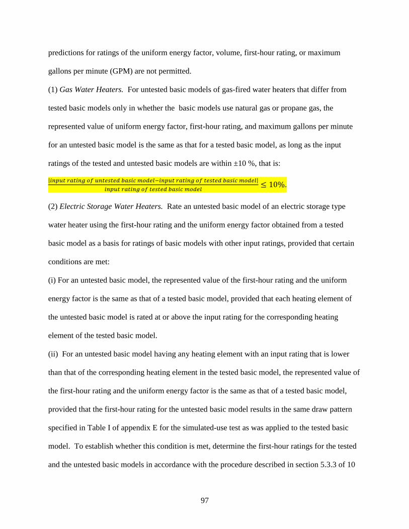
97
predictions for ratings of the uniform energy factor, volume, first-hour rating, or maximum
gallons per minute (GPM) are not permitted.
(1) Gas Water Heaters. For untested basic models of gas-fired water heaters that differ from
tested basic models only in whether the basic models use natural gas or propane gas, the
represented value of uniform energy factor, first-hour rating, and maximum gallons per minute
for an untested basic model is the same as that for a tested basic model, as long as the input
ratings of the tested and untested basic models are within ±10 %, that is:
| |
.
(2) Electric Storage Water Heaters. Rate an untested basic model of an electric storage type
water heater using the first-hour rating and the uniform energy factor obtained from a tested
basic model as a basis for ratings of basic models with other input ratings, provided that certain
conditions are met:
(i) For an untested basic model, the represented value of the first-hour rating and the uniform
energy factor is the same as that of a tested basic model, provided that each heating element of
the untested basic model is rated at or above the input rating for the corresponding heating
element of the tested basic model.
(ii) For an untested basic model having any heating element with an input rating that is lower
than that of the corresponding heating element in the tested basic model, the represented value of
the first-hour rating and the uniform energy factor is the same as that of a tested basic model,
provided that the first-hour rating for the untested basic model results in the same draw pattern
specified in Table I of appendix E for the simulated-use test as was applied to the tested basic
model. To establish whether this condition is met, determine the first-hour ratings for the tested
and the untested basic models in accordance with the procedure described in section 5.3.3 of 10
98
CFR part 430, subpart B, appendix E, then compare the appropriate draw pattern specified in
Table I of appendix E for the first-hour rating of the tested basic model with that for the untested
basic model. If this condition is not met, then the untested basic model must be tested and the
appropriate sampling provisions applied to determine its uniform energy factor in accordance
with appendix E and this part.
5. Section 429.134 is amended by reserving paragraph (c) and adding paragraph (d) to
read as follows:
§ 429.134 Product-specific enforcement provisions.
* * * * *
(c) [Reserved].
(d) Residential Water Heaters and Residential-Duty Commercial Water Heaters. (1)
Verification of first-hour rating and maximum GPM rating. The first-hour rating or maximum
gallons per minute (GPM) rating of the basic model will be measured pursuant to the test
requirements of 10 CFR part 430 for each unit tested. The mean of the measured values will be
compared to the rated values of first-hour rating or maximum GPM rating as certified by the
manufacturer. The certified rating will be considered valid only if the measurement is within
five percent of the certified rating.
(i) If the rated value of first-hour rating or maximum GPM rating is found to be within 5
percent of the mean of the measured values, then the rated value will be used as the basis for
determining the applicable draw pattern pursuant to the test requirements of 10 CFR part 430 for
each unit tested.

99
(ii) If the rated value of first-hour rating or maximum GPM rating is found to vary more
than 5 percent from the measured values, then the mean of the measured values will serve as the
basis for determining the applicable draw pattern pursuant to the test requirements of 10 CFR
part 430 for each unit tested.
(2) Verification of rated storage volume. The storage volume of the basic model will be
measured pursuant to the test requirements of 10 CFR part 430 for each unit tested. The mean of
the measured values will be compared to the rated storage volume as certified by the
manufacturer. The rated value will be considered valid only if the measurement is within five
percent of the certified rating.
(i) If the rated storage volume is found to be within 5 percent of the mean of the
measured value of storage volume, then that value will be used as the basis for calculation of the
required uniform energy factor for the basic model.
(ii) If the rated storage volume is found to vary more than 5 percent from the mean of the
measured values, then the mean of the measured values will be used as the basis for calculation
of the required uniform energy factor for the basic model.
PART 430 – ENERGY CONSERVATION PROGRAM FOR CONSUMER PRODUCTS
6. The authority citation for part 430 continues to read as follows:
Authority: 42 U.S.C. 6291-6309; 28 U.S.C. 2461 note.
100
7. Section 430.2 is amended by adding the definitions of “Electric heat pump water
heater,” “Electric instantaneous water heater,” “Electric storage water heater,” “Gas-fired
instantaneous water heater,” “Gas-fired storage water heater,” “Gas-fired heat pump water
heater,” “Oil-fired instantaneous water heater,” and “Oil-fired storage water heater” in
alphabetical order, to read as follows:
§ 430.2 Definitions.
* * * * *
Electric heat pump water heater means a water heater that uses electricity as the energy source,
has a maximum current rating of 24 amperes (including the compressor and all auxiliary
equipment such as fans, pumps, controls, and, if on the same circuit, any resistive elements) at an
input voltage of no greater than 250 volts, has a rated storage capacity of 120 gallons (450 liters)
or less, is designed to transfer thermal energy from one temperature level to a higher temperature
level for the purpose of heating water, including all ancillary equipment such as fans, storage
tanks, pumps, or controls necessary for the device to perform its function, and is designed to heat
and store water at a thermostatically-controlled temperature less than or equal to 180°F (82°C).
* * * * *
Electric instantaneous water heater means a water heater that uses electricity as the energy
source, has a nameplate input rating of 12 kW (40,956 Btu/h) or less, contains no more than one
gallon of water per 4,000 Btu per hour of input, and is designed to provide outlet water at a
controlled temperature less than or equal to 180°F (82°C). The unit may use a fixed or variable
burner input.
* * * * *
101
Electric storage water heater means a water heater that uses electricity as the energy source, has
a nameplate input rating of 12 kW (40,956 Btu/h) or less, has a rated storage capacity of 120
gallons (450 liters) or less, contains more than one gallon of water per 4,000 Btu per hour of
input, and may be designed to heat and store water at a thermostatically-controlled temperature
less than or equal to 180°F (82°C).
* * * * *
Gas-fired heat pump water heater means a water heater that uses gas as the main energy source,
has a nameplate input rating of 75,000 Btu/h (79 MJ/h) or less, has a maximum current rating of
24 amperes (including all auxiliary equipment such as fans, pumps, controls, and, if on the same
circuit, any resistive elements) at an input voltage of no greater than 250 volts, has a rated
storage volume not more than 120 gallons (450 liters), and is designed to transfer thermal energy
from one temperature level to a higher temperature level to deliver water at a thermostatically
controlled temperature less than or equal to 180°F (82°C).
Gas-fired instantaneous water heater means a water heater that uses gas as the main energy
source, has a nameplate input rating less than 200,000 Btu/h (210 MJ/h), contains no more than
one gallon of water per 4,000 Btu per hour of input, and is designed to provide outlet water at a
controlled temperature less than or equal to 180°F (82°C). The unit may use a fixed or variable
burner input.
Gas-fired storage water heater means a water heater that uses gas as the main energy source, has
a nameplate input rating of 75,000 Btu/h (79 MJ/h) or less, has a rated storage capacity of 120
gallons (450 liters) or less, contains more than one gallon of water per 4,000 Btu per hour of
102
input, and is designed to heat and store water at a thermostatically-controlled temperature less
than or equal to 180°F (82°C).
* * * * *
Oil-fired instantaneous water heater means a water heater that uses oil as the main energy
source, has a nameplate input rating of 210,000 Btu/h (220 MJ/h) or less, contains no more than
one gallon of water per 4,000 Btu per hour of input, and is designed to provide outlet water at a
controlled temperature less than or equal to 180°F (82°C). The unit may use a fixed or variable
burner input.
Oil-fired storage water heater means a water heater that uses oil as the main energy source, has a
nameplate input rating of 105,000 Btu/h (110 MJ/h) or less, has a rated storage capacity of 120
gallons (450 liters) or less, contains more than one gallon of water per 4,000 Btu per hour of
input, and is designed to heat and store water at a thermostatically-controlled temperature less
than or equal to 180°F (82°C).
* * * * *
8. Section 430.3 is amended by:
a. Redesignating paragraphs (h) through (t) as (i) through (u), respectively; and
b. Adding a new paragraph (h).
The additions read as follows:
§ 430.3 Materials incorporated by reference.
* * * * *
103
(h) ASTM. American Society for Testing and Materials International, 100 Barr Harbor
Drive, P.O. Box C700, West Conshohocken, PA 19428-2959 (www.astm.org).
(1) ASTM D 2156-09 (“ASTM D2156”), Standard Test Method for Smoke Density in
Flue Gases from Burning Distillate Fuels, approved December 1, 2009, IBR approved for
appendix E to subpart B.
(2) [Reserved].
* * * * *
9. Section 430.23 is amended by revising paragraph (e) to read as follows:
§ 430.23 Test procedures for the measurement of energy and water consumption.
* * * * *
(e) Water Heaters. (1) The estimated annual operating cost for water heaters shall be—
(i) For a gas or oil water heater, the sum of: the product of the annual gas or oil energy
consumption, determined according to section 6.1.10 or 6.2.7 of appendix E of this subpart,
times the representative average unit cost of gas or oil, as appropriate, in dollars per Btu as
provided by the Secretary; plus the product of the annual electric energy consumption,
determined according to section 6.1.9 or 6.2.6 of appendix E of this subpart, times the
representative average unit cost of electricity in dollars per kilowatt-hour as provided by the
Secretary, the resulting sum then being rounded off to the nearest dollar per year.
(ii) For an electric water heater, the product of the annual energy consumption,
determined according to section 6.1.9 or 6.2.6 of appendix E of this subpart, times the
representative average unit cost of electricity in dollars per kilowatt-hour as provided by the
Secretary, the resulting product then being rounded off to the nearest dollar per year.
104
(2) For an individual test, the tested uniform energy factor for a water heater shall be —
(i) For a gas or oil water heater, as determined by section 6.1.7 or 6.2.4 of appendix E of
this subpart rounded to the nearest 0.01.
(ii) For an electric water heater, as determined by section 6.1.7 or 6.2.4 of appendix E of
this subpart rounded to the nearest 0.01.
* * * * *
10. Appendix E to Subpart B of Part 430 is revised to read as follows:
APPENDIX E TO SUBPART B OF PART 430–UNIFORM TEST METHOD FOR MEASURING THE
ENERGY CONSUMPTION OF WATER HEATERS
Note: After December 31, 2015, any representations made with respect to the energy use or
efficiency of residential water heaters and commercial water heaters covered by this test method
must be made in accordance with the results of testing pursuant to this appendix. (Because the
statute permits use of a conversion factor until the later of December 31, 2015 or one year after
publication of a conversion factor final rule, DOE may amend the mandatory compliance date
for use of this amended test procedure, as necessary.)
Manufacturers conducting tests of residential water heaters and commercial water heaters
covered by this test method after [INSERT DATE 365 DAYS AFTER DATE OF
PUBLICATION IN THE FEDERAL REGISTER] and prior to December 31, 2015, must
conduct such test in accordance with either this appendix or the previous test method. For
105
residential water heaters, the previous test method is appendix E as it appeared at 10 CFR part
430, subpart B, appendix E, in the 10 CFR parts 200 to 499 edition revised as of January 1, 2014.
For commercial water heaters, the previous test method is 10 CFR 431.106 in the 10 CFR parts
200 to 499 edition revised as of January 1, 2014. Any representations made with respect to the
energy use or efficiency of such water heaters must be in accordance with whichever version is
selected.
1. Definitions.
1.1. Cut-in means the time when or water temperature at which a water heater control or
thermostat acts to increase the energy or fuel input to the heating elements,
compressor, or burner.
1.2. Cut-out means the time when or water temperature at which a water heater control or
thermostat acts to reduce to a minimum the energy or fuel input to the heating
elements, compressor, or burner.
1.3. Design Power Rating means the nominal power rating that a water heater
manufacturer assigns to a particular design of water heater, expressed in kilowatts or
Btu (kJ) per hour as appropriate.
1.4. Draw Cluster means a collection of water draws initiated during the simulated-use
test during which no successive draws are separated by more than 2 hours..
1.5. First-Hour Rating means an estimate of the maximum volume of “hot” water that a
storage-type water heater can supply within an hour that begins with the water heater
106
fully heated (i.e., with all thermostats satisfied). It is a function of both the storage
volume and the recovery rate.
1.6. Flow-activated describes an operational scheme in which a water heater initiates and
terminates heating based on sensing flow.
1.7. Heat Trap means a device that can be integrally connected or independently attached
to the hot and/or cold water pipe connections of a water heater such that the device
will develop a thermal or mechanical seal to minimize the recirculation of water due
to thermal convection between the water heater tank and its connecting pipes.
1.8. Maximum GPM (L/min) Rating means the maximum gallons per minute (liters per
minute) of hot water that can be supplied by an instantaneous water heater while
maintaining a nominal temperature rise of 67°F (37.3°C) during steady-state
operation, as determined by testing in accordance with section 5.3.2 of this appendix.
1.9. Rated Storage Volume means the water storage capacity of a water heater, in gallons
(liters), as certified by the manufacturer pursuant to 10 CFR part 429.
1.10. Recovery Efficiency means the ratio of energy delivered to the water to the energy
content of the fuel consumed by the water heater.
1.11. Recovery Period means the time when the main burner of a storage water heater is
raising the temperature of the stored water.
1.12. Standby means the time, in hours, during which water is not being withdrawn from
the water heater. There are two standby time intervals used within this test
procedure: stby,1 represents the elapsed time between the time at which the maximum
mean tank temperature is observed after the first draw cluster and the minute prior to
the start of the first draw following the end of the first draw cluster of the 24-hour

107
simulated-use test; stby,2 represents the total time during the 24-hour simulated-use
test when water is not being withdrawn from the water heater.
1. 13. Symbol Usage. The following identity relationships are provided to help clarify the
symbology used throughout this procedure:
Cp specific heat of water
Eannual annual energy consumption of a water heater
Eannual,e annual electrical energy consumption of a water heater
Eannual,f annual fossil-fuel energy consumption of a water heater
Fhr first-hour rating of a storage-type water heater
Fmax maximum GPM (L/min) rating of an instantaneous water heater rated at a
temperature rise of 67 °F (37.3 °C)
i a subscript to indicate the draw number during a test
Mi mass of water removed during the ith draw of the 24-hour simulated-use test
M*
i for storage-type water heaters, mass of water removed during the ith draw during
the first-hour rating test
M10m for instantaneous water heaters, mass of water removed continuously during a 10-
minute interval in the maximum GPM (L/min) rating test
n for storage-type water heaters, total number of draws during the first-hour rating
test
N total number of draws during the 24-hour simulated-use test
Q total fossil fuel and/or electric energy consumed during the entire 24-hour
simulated-use test
Qd daily water heating energy consumption adjusted for net change in internal energy
108
Qda Qd with adjustment for variation of tank to ambient air temperature difference from
nominal value
Qdm overall adjusted daily water heating energy consumption including Qda and QHWD
Qe total electrical energy used during the 24-hour simulated-use test
Qf total fossil fuel energy used by the water heater during the 24-hour simulated-use
test
Qhr hourly standby losses
QHW daily energy consumption to heat water at the measured average temperature rise
across the water heater
QHW,67°F daily energy consumption to heat quantity of water removed during test over a
temperature rise of 67°F (37.3°C)
QHWD adjustment to daily energy consumption, QHW, due to variation of the temperature
rise across the water heater not equal to the nominal value of 67°F
Qr energy consumption of water heater from the beginning of the test to the end of the
first recovery period following the first draw, which may extend beyond subsequent
draws
Qstby total energy consumed by the water heater during the standby time interval stby,1
Qsu,0 total fossil fuel and/or electric energy consumed from the beginning of the test to
the end of the cutout following the first draw cluster
Qsu,f total fossil fuel and/or electric energy consumed from the beginning of the test to
the initiation of the first draw following the first draw cluster
0 mean tank temperature at the beginning of the 24-hour simulated-use test
24 mean tank temperature at the end of the 24-hour simulated-use test
109
a,stby average ambient air temperature during standby periods of the 24-hour simulated-
use test
del for flow-activated water heaters, average outlet water temperature during a 10-
minute continuous draw interval in the maximum GPM (L/min) rating test
del,i average outlet water temperature during the ith draw of the 24-hour simulated-use
test
in for flow-activated water heaters, average inlet water temperature during a 10-
minute continuous draw interval in the maximum GPM (L/min) rating test
in,i average inlet water temperature during the ith draw of the 24-hour simulated-use
test
max,1 maximum measured mean tank temperature after cut-out following the first draw of
the 24-hour simulated-use test
su,0 maximum measured mean tank temperature at the beginning of the standby period
which occurs after cut-out following the final draw of the first draw cluster
su,f measured mean tank temperature at the end of the standby period which occurs at
the minute prior to commencement of the first draw that follows the end of the first
draw cluster
*del,i for storage-type water heaters, average outlet water temperature during the ith draw
(i=1 to n) of the first-hour rating test
*max,i for storage-type water heaters, maximum outlet water temperature observed during
the ith draw (i=1 to n) of the first-hour rating test
*min,i for storage-type water heaters, minimum outlet water temperature to terminate the
ith draw (i=1 to n) of the first-hour rating test
110
UA standby loss coefficient of a storage-type water heater
UEF uniform energy factor of a water heater
Vi volume of water removed during the ith draw (i = 1 to N) of the 24-hour simulated-
use test
V*
i volume of water removed during the ith draw (i=1 to n) of the first-hour rating test
V10m for flow-activated water heaters, volume of water removed continuously during a
10-minute interval in the maximum GPM (L/min) rating test
Vst measured storage volume of the storage tank
Wf weight of storage tank when completely filled with water
Wt tare weight of storage tank when completely empty of water
r recovery efficiency
density of water
stby,1 elapsed time between the time the maximum mean tank temperature is observed
after the first draw cluster and the minute prior to the start of the first draw
following the first draw cluster
stby,2 overall time of standby periods when no water is withdrawn during the 24-hour
simulated-use test
1.14. Temperature controller means a device that is available to the user to adjust the temperature
of the water inside a storage-type water heater or the outlet water temperature.
1.15. Uniform Energy Factor means the measure of water heater overall efficiency.
2. Test Conditions.
111
2.1 Installation Requirements. Tests shall be performed with the water heater and
instrumentation installed in accordance with section 4 of this appendix.
2.2 Ambient Air Temperature. The ambient air temperature shall be maintained between
65.0°F and 70.0 °F (18.3 °C and 21.1 °C) on a continuous basis. For heat pump water heaters,
the dry bulb temperature shall be maintained at 67.5 °F ± 1 °F (19.7 °C ± 0.6 °C) and the relative
humidity shall be maintained at 50 % ± 2 % throughout the test.
2.3 Supply Water Temperature. The temperature of the water being supplied to the water
heater shall be maintained at 58 °F ± 2°F (14.4°C ± 1.1°C) throughout the test.
2.4 Outlet Water Temperature. The temperature controllers of a storage-type water heater
shall be set so that water is delivered at a temperature of 125°F ± 5°F (51.7°C ± 2.8°C).
2.5 Set Point Temperature. The temperature controller of instantaneous water heaters shall
be set to deliver water at a temperature of 125°F ± 5°F (51.7°C ± 2.8°C).
2.6 Supply Water Pressure. During the test when water is not being withdrawn, the supply
pressure shall be maintained between 40 psig (275 kPa) and the maximum allowable pressure
specified by the water heater manufacturer.
2.7 Electrical and/or Fossil Fuel Supply.
2.7.1 Electrical. Maintain the electrical supply voltage to within ±1 % of the center of the
voltage range specified by the water heater and/or heat pump manufacturer.
2.7.2 Natural Gas. Maintain the supply pressure in accordance with the manufacturer’s
specifications. If the supply pressure is not specified, maintain a supply pressure of 7-10 inches
of water column (1.7-2.5 kPa). If the water heater is equipped with a gas appliance pressure
regulator, the regulator outlet pressure shall be within ± 10 % of the manufacturer’s specified
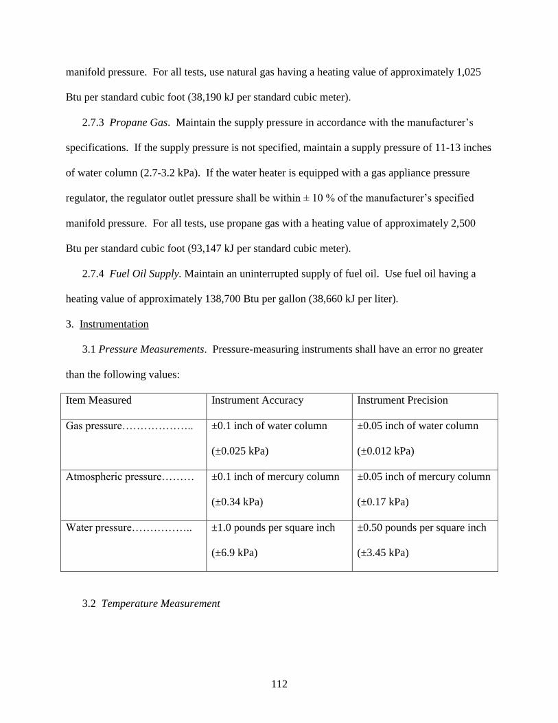
112
manifold pressure. For all tests, use natural gas having a heating value of approximately 1,025
Btu per standard cubic foot (38,190 kJ per standard cubic meter).
2.7.3 Propane Gas. Maintain the supply pressure in accordance with the manufacturer’s
specifications. If the supply pressure is not specified, maintain a supply pressure of 11-13 inches
of water column (2.7-3.2 kPa). If the water heater is equipped with a gas appliance pressure
regulator, the regulator outlet pressure shall be within ± 10 % of the manufacturer’s specified
manifold pressure. For all tests, use propane gas with a heating value of approximately 2,500
Btu per standard cubic foot (93,147 kJ per standard cubic meter).
2.7.4 Fuel Oil Supply. Maintain an uninterrupted supply of fuel oil. Use fuel oil having a
heating value of approximately 138,700 Btu per gallon (38,660 kJ per liter).
3. Instrumentation
3.1 Pressure Measurements. Pressure-measuring instruments shall have an error no greater
than the following values:
Item Measured Instrument Accuracy Instrument Precision
Gas pressure……………….. ±0.1 inch of water column
(±0.025 kPa)
±0.05 inch of water column
(±0.012 kPa)
Atmospheric pressure……… ±0.1 inch of mercury column
(±0.34 kPa)
±0.05 inch of mercury column
(±0.17 kPa)
Water pressure…………….. ±1.0 pounds per square inch
(±6.9 kPa)
±0.50 pounds per square inch
(±3.45 kPa)
3.2 Temperature Measurement
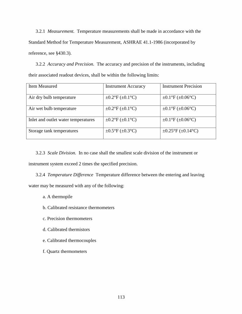
113
3.2.1 Measurement. Temperature measurements shall be made in accordance with the
Standard Method for Temperature Measurement, ASHRAE 41.1-1986 (incorporated by
reference, see §430.3).
3.2.2 Accuracy and Precision. The accuracy and precision of the instruments, including
their associated readout devices, shall be within the following limits:
Item Measured Instrument Accuracy Instrument Precision
Air dry bulb temperature ±0.2°F (±0.1°C) ±0.1°F (±0.06°C)
Air wet bulb temperature ±0.2°F (±0.1°C) ±0.1°F (±0.06°C)
Inlet and outlet water temperatures ±0.2°F (±0.1°C) ±0.1°F (±0.06°C)
Storage tank temperatures ±0.5°F (±0.3°C) ±0.25°F (±0.14°C)
3.2.3 Scale Division. In no case shall the smallest scale division of the instrument or
instrument system exceed 2 times the specified precision.
3.2.4 Temperature Difference Temperature difference between the entering and leaving
water may be measured with any of the following:
a. A thermopile
b. Calibrated resistance thermometers
c. Precision thermometers
d. Calibrated thermistors
e. Calibrated thermocouples
f. Quartz thermometers
114
3.2.5 Thermopile Construction. If a thermopile is used, it shall be made from calibrated
thermocouple wire taken from a single spool. Extension wires to the recording device shall also
be made from that same spool.
3.2.6 Time Constant. The time constant of the instruments used to measure the inlet and
outlet water temperatures shall be no greater than 2 seconds.
3.3 Liquid Flow Rate Measurement. The accuracy of the liquid flow rate measurement,
using the calibration if furnished, shall be equal to or less than ±1 % of the measured value in
mass units per unit time.
3.4 Electrical Energy. The electrical energy used shall be measured with an instrument and
associated readout device that is accurate within ±0.5 % of the reading.
3.5 Fossil Fuels. The quantity of fuel used by the water heater shall be measured with an
instrument and associated readout device that is accurate within ±1 % of the reading.
3.6 Mass Measurements. For mass measurements greater than or equal to 10 pounds (4.5
kg), a scale that is accurate within ±0.5 % of the reading shall be used to make the measurement.
For mass measurements less than 10 pounds (4.5 kg), the scale shall provide a measurement that
is accurate within ±0.1 pound (0.045 kg).
3.7 Heating Value. The higher heating value of the natural gas, propane, or fuel oil shall be
measured with an instrument and associated readout device that is accurate within ±1% of the
reading. The heating values of natural gas and propane must be corrected from those reported at
standard temperature and pressure conditions to provide the heating value at the temperature and
pressure measured at the fuel meter.
3.8 Time. The elapsed time measurements shall be measured with an instrument that is
accurate within ±0.5 seconds per hour.
115
3.9 Volume. Volume measurements shall be measured with an accuracy of ±2% of the total
volume.
3.10 Relative Humidity. If a relative humidity (RH) transducer is used to measure the
relative humidity of the surrounding air while testing heat pump water heaters, the relative
humidity shall be measured with an accuracy of ±1.5 % RH.
4. Installation
4.1 Water Heater Mounting. A water heater designed to be freestanding shall be placed on a
¾ inch (2 cm) thick plywood platform supported by three 2 x 4 inch (5 cm x 10 cm) runners. If
the water heater is not approved for installation on combustible flooring, suitable non-
combustible material shall be placed between the water heater and the platform. Counter-top
water heaters shall be placed against a simulated wall section. Wall-mounted water heaters shall
be supported on a simulated wall in accordance with the manufacturer-published installation
instructions. When a simulated wall is used, the construction shall be 2 x 4 inch (5 cm x 10 cm)
studs, faced with ¾ inch (2 cm) plywood. For heat pump water heaters not delivered as a single
package, the units shall be connected in accordance with the manufacturer-published installation
instructions and the overall system shall be placed on the above-described plywood platform. If
installation instructions are not provided by the heat pump manufacturer, uninsulated 8 foot (2.4
m) long connecting hoses having an inside diameter of 5/8 inch (1.6 cm) shall be used to connect
the storage tank and the heat pump water heater. The testing of the water heater shall occur in an
area that is protected from drafts of more than 50 ft/min (0.25 m/s) from room ventilation
registers, windows, or other external sources of air movement.
4.2 Water Supply. Connect the water heater to a water supply capable of delivering water at
conditions as specified in sections 2.3 and 2.6 of this appendix.
116
4.3 Water Inlet and Outlet Configuration. For freestanding water heaters that are taller than
36 inches (91.4 cm), inlet and outlet piping connections shall be configured in a manner
consistent with Figures 1 and 2 of section 6.4.6 of this appendix. Inlet and outlet piping
connections for wall-mounted water heaters shall be consistent with Figure 3 of section 6.4.6 of
this appendix. For freestanding water heaters that are 36 inches or less in height and not supplied
as part of a counter-top enclosure (commonly referred to as an under-the-counter model), inlet
and outlet piping shall be installed in a manner consistent with Figures 4, 5, or 6 of section 6.4.6
of this appendix. For water heaters that are supplied with a counter-top enclosure, inlet and
outlet piping shall be made in a manner consistent with Figures 7a and 7b of section 6.4.6 of this
appendix, respectively. The vertical piping noted in Figures 7a and 7b shall be located (whether
inside the enclosure or along the outside in a recessed channel) in accordance with the
manufacturer-published installation instructions.
All dimensions noted in Figures 1 through 7 of section 6.4.6 of this appendix must be
achieved. All piping between the water heater and inlet and outlet temperature sensors, noted as
TIN and TOUT in the figures, shall be Type “L” hard copper having the same diameter as the
connections on the water heater. Unions may be used to facilitate installation and removal of the
piping arrangements. Install a pressure gauge and diaphragm expansion tank in the supply water
piping at a location upstream of the inlet temperature sensor. Install an appropriately rated
pressure and temperature relief valve on all water heaters at the port specified by the
manufacturer. Discharge piping for the relief valve must be non-metallic. If heat traps, piping
insulation, or pressure relief valve insulation are supplied with the water heater, they must be
installed for testing. Except when using a simulated wall, provide sufficient clearance such that
none of the piping contacts other surfaces in the test room.
117
4.4 Fuel and/or Electrical Power and Energy Consumption. Install one or more instruments
that measure, as appropriate, the quantity and rate of electrical energy and/or fossil fuel
consumption in accordance with section 3 of this appendix.
4.5 Internal Storage Tank Temperature Measurements. For water heaters with rated storage
volumes greater than or equal to 20 gallons, install six temperature measurement sensors inside
the water heater tank with a vertical distance of at least 4 inches (100 mm) between successive
sensors. For water heaters with rated storage volumes between 2 and 20 gallons, install three
temperature measurement sensors inside the water heater tank. Position a temperature sensor at
the vertical midpoint of each of the six equal volume nodes within a tank larger than 20 gallons
or the three equal volume nodes within a tank between 2 and 20 gallons. Nodes designate the
equal volumes used to evenly partition the total volume of the tank. As much as is possible, the
temperature sensor should be positioned away from any heating elements, anodic protective
devices, tank walls, and flue pipe walls. If the tank cannot accommodate six temperature sensors
and meet the installation requirements specified above, install the maximum number of sensors
that comply with the installation requirements. Install the temperature sensors through: (1) the
anodic device opening; (2) the relief valve opening; or (3) the hot water outlet. If installed
through the relief valve opening or the hot water outlet, a tee fitting or outlet piping, as
applicable, must be installed as close as possible to its original location. If the relief valve
temperature sensor is relocated, and it no longer extends into the top of the tank, install a
substitute relief valve that has a sensing element that can reach into the tank. If the hot water
outlet includes a heat trap, install the heat trap on top of the tee fitting. Cover any added fittings
with thermal insulation having an R value between 4 and 8 h•ft2•°F/Btu (0.7 and 1.4 m
2•°C/W).

118
4.6 Ambient Air Temperature Measurement. Install an ambient air temperature sensor at the
vertical mid-point of the water heater and approximately 2 feet (610 mm) from the surface of the
water heater. Shield the sensor against radiation.
4.7 Inlet and Outlet Water Temperature Measurements. Install temperature sensors in the
cold-water inlet pipe and hot-water outlet pipe as shown in Figures 1, 2, 3, 4, 5, 6, 7a, and 7b of
section 6.4.6 of this appendix, as applicable.
4.8 Flow Control. Install a valve or valves to provide flow as specified in sections 5.3 and
5.4 of this appendix.
4.9 Flue Requirements.
4.9.1 Gas-Fired Water Heaters. Establish a natural draft in the following manner. For gas-
fired water heaters with a vertically discharging draft hood outlet, connect to the draft hood
outlet a 5-foot (1.5-meter) vertical vent pipe extension with a diameter equal to the largest flue
collar size of the draft hood. For gas-fired water heaters with a horizontally discharging draft
hood outlet, connect to the draft hood outlet a 90-degree elbow with a diameter equal to the
largest flue collar size of the draft hood, connect a 5-foot (1.5-meter) length of vent pipe to that
elbow, and orient the vent pipe to discharge vertically upward.. Install direct-vent gas-fired
water heaters with venting equipment specified in the manufacturer’s instructions using the
minimum vertical and horizontal lengths of vent pipe recommended by the manufacturer.
4.9.2 Oil-Fired Water Heaters. Establish a draft at the flue collar at the value specified in
the manufacturer’s instructions. Establish the draft by using a sufficient length of vent pipe
connected to the water heater flue outlet, and directed vertically upward. For an oil-fired water
heater with a horizontally discharging draft hood outlet, connect to the draft hood outlet a 90-
degree elbow with a diameter equal to the largest flue collar size of the draft hood, connect to the
119
elbow fitting a length of vent pipe sufficient to establish the draft, and orient the vent pipe to
discharge vertically upward. Direct-vent oil-fired water heaters should be installed with venting
equipment as specified in the manufacturer’s instructions, using the minimum vertical and
horizontal lengths of vent pipe recommended by the manufacturer.
5. Test Procedures
5.1 Operational Mode Selection. For water heaters that allow for multiple user-selected
operational modes, all procedures specified in this appendix shall be carried out with the water
heater in the same operational mode (i.e., only one mode). This operational mode shall be the
default mode (or similarly-named, suggested mode for normal operation) as defined by the
manufacturer in its product literature for giving selection guidance to the consumer. For heat
pump water heaters, if a default mode is not defined in the product literature, each test shall be
conducted under an operational mode in which both the heat pump and any electric resistance
backup heating element(s) are activated by the unit’s control scheme, and which can achieve the
internal storage tank temperature specified in this test procedure; if multiple operational modes
meet these criteria, the water heater shall be tested under the most energy-intensive mode. If no
default mode is specified and the unit does not offer an operational mode that utilizes both the
heat pump and the electric resistance backup heating element(s), the first-hour rating test and the
simulated-use test shall be tested in heat-pump-only mode. For other types of water heaters
where a default mode is not specified, test the unit in all modes and rate the unit using the results
of the most energy-intensive mode.
5.2 Water Heater Preparation.
5.2.1 Determination of Storage Tank Volume. For water heaters with a rated storage volume
greater than or equal to 2 gallons, determine the storage capacity, Vst, of the water heater under
120
test, in gallons (liters), by subtracting the tare weight – measured while the tank is empty – from
the gross weight of the storage tank when completely filled with water (with all air eliminated
and line pressure applied as described in section 2.5 of this appendix) and dividing the resulting
net weight by the density of water at the measured temperature.
5.2.2 Setting the Outlet Discharge Temperature.
5.2.2.1 Flow-Activated Water Heaters, including certain instantaneous water heaters and
certain storage-type water heaters. Initiate normal operation of the water heater at the full
input rating for electric water heaters and at the maximum firing rate specified by the
manufacturer for gas or oil water heaters. Monitor the discharge water temperature and set to a
value of 125°F ± 5°F (51.7°C ± 2.8°C) in accordance with the manufacturer’s instructions. If the
water heater is not capable of providing this discharge temperature when the flow rate is 1.7
gallons ± 0.25 gallons per minute (6.4 liters ± 0.95 liters per minute), then adjust the flow rate as
necessary to achieve the specified discharge water temperature. Once the proper temperature
control setting is achieved, the setting must remain fixed for the duration of the maximum GPM
test and the simulated-use test.
5.2.2.2 Storage-Type Water Heaters that Are Not Flow-Activated.
5.2.2.2.1 Tanks with a Single Temperature Controller.
5.2.2.2.1.1 Water Heaters with Rated Volumes Less than 20 Gallons. Starting with a tank at
the supply water temperature, initiate normal operation of the water heater. After cut-out, initiate
a draw from the water heater at a flow rate of 1.0 gallon ± 0.25 gallons per minute (3.8 liters ±
0.95 liters per minute ) for 2 minutes. Starting 15 seconds after commencement of draw, record
the outlet temperature at 15-second intervals until the end of the 2-minute period. Determine
whether the maximum outlet temperature is within the range of 125°F ± 5°F (51.7°C ± 2.8°C).
121
If not, turn off the water heater, adjust the temperature controller, and then drain and refill the
tank with supply water. Then, once again, initiate normal operation of the water heater, and
repeat the 2-minute outlet temperature test following cut-out. Repeat this sequence until the
maximum outlet temperature during the 2-minute test is within 125°F ± 5°F (51.7°C ± 2.8°C).
Once the proper temperature control setting is achieved, the setting must remain fixed for the
duration of the first-hour rating test and the simulated-use test such that a second identical
simulated-use test run immediately following the one specified in section 5.4 would result in
average delivered water temperatures that are within the bounds specified in section 2.4 of this
appendix.
5.2.2.2.1.2 Water Heaters with Rated Volumes Greater than or Equal to 20 Gallons.
Starting with a tank at the supply water temperature, initiate normal operation of the water
heater. After cut-out, initiate a draw from the water heater at a flow rate of 1.7 gallons ± 0.25
gallons per minute (6.4 liters ± 0.95 liters per minute) for 5 minutes. Starting 15 seconds after
commencement of draw, record the outlet temperature at 15-second intervals until the end of the
5-minute period. Determine whether the maximum outlet temperature is within the range of
125°F ± 5°F (51.7°C ± 2.8°C). If not, turn off the water heater, adjust the temperature controller,
and then drain and refill the tank with supply water. Then, once again, initiate normal operation
of the water heater, and repeat the 5-minute outlet temperature test following cut-out. Repeat
this sequence until the maximum outlet temperature during the 5-minute test is within of 125°F ±
5°F (51.7°C ± 2.8°C). Once the proper temperature control setting is achieved, the setting must
remain fixed for the duration of the first-hour rating test and the simulated-use test such that a
second identical simulated-use test run immediately following the one specified in section 5.4

122
would result in average delivered water temperatures that are within the bounds specified in
section 2.4 of this appendix.
5.2.2.2.2 Tanks with Two or More Temperature Controllers. Verify the temperature
controller set-point while removing water in accordance with the procedure set forth for the first-
hour rating test in section 5.3.3 of this appendix. The following criteria must be met to ensure
that all temperature controllers are set to deliver water at 125°F ± 5°F (51.7°C ± 2.8°C):
(a) At least 50 percent of the water drawn during the first draw of the first-hour rating test
procedure shall be delivered at a temperature of 125°F ± 5°F (51.7°C ± 2.8°C).
(b) No water is delivered above 130°F (54.4°C) during first-hour rating test.
(c) The delivery temperature measured 15 seconds after commencement of each draw begun
prior to an elapsed time of 60 minutes from the start of the test shall be at 125°F ± 5°F (51.7°C ±
2.8°C).
If these conditions are not met, turn off the water heater, adjust the temperature controllers,
and then drain and refill the tank with supply water. Repeat the procedure described at the start
of section 5.2.2.2.2 until the criteria for setting the temperature controllers is met.
If the conditions stated above are met, the data obtained during the process of verifying the
temperature control set-points may be used in determining the first-hour rating provided that all
other conditions and methods required in sections 2 and 5.2.4 in preparing the water heater were
followed.
5.2.3 Power Input Determination. For all water heaters except electric types, initiate normal
operation (as described in section 5.1) and determine the power input, P, to the main burners
(including pilot light power, if any) after 15 minutes of operation. If the water heater is equipped
123
with a gas appliance pressure regulator, the regulator outlet pressure shall be set within ±10% of
that recommended by the manufacturer. For oil-fired water heaters, the fuel pump pressure shall
be within ±10% of the manufacturer’s specified pump pressure. Adjust all burners to achieve an
hourly Btu (kJ) rating that is within ±2% of the value specified by the manufacturer. For an oil-
fired water heater, adjust the burner to give a CO2 reading recommended by the manufacturer
and an hourly Btu (kJ) rating that is within ±2% of that specified by the manufacturer. Smoke in
the flue may not exceed No. 1 smoke as measured by the procedure in ASTM D2156
(incorporated by reference, see §430.3).
5.2.4 Soak-In Period for Water Heaters with Rated Storage Volumes Greater than or
Equal to 2 Gallons. For storage-type water heaters and instantaneous water heaters having
greater than 2 gallons (7.6 liters) of storage (including heat pump water heaters having greater
than 2 gallons of storage), the water heater must sit filled with water and without any draws
taking place for at least 12 hours after initially being energized so as to achieve the nominal
temperature set-point within the tank and with the unit connected to a power source.
5.3 Delivery Capacity Tests.
5.3.1 General. For flow-activated water heaters, conduct the maximum GPM test, as
described in section 5.3.2, Maximum GPM Rating Test for Flow-Activated Water Heaters, of this
appendix. For all other water heaters, conduct the first-hour rating test as described in section
5.3.3 of this appendix.
5.3.2 Maximum GPM Rating Test for Flow-Activated Water Heaters. Establish normal
water heater operation at the full input rate for electric water heaters and at the maximum firing
rate for gas or oil water heaters with the discharge water temperature set in accordance with
section 5.2.2.1 of this appendix.
124
For this 10-minute test, either collect the withdrawn water for later measurement of the total
mass removed or use a water meter to directly measure the water volume removed. Initiate
water flow through the water heater and record the inlet and outlet water temperatures beginning
15 seconds after the start of the test and at subsequent 5-second intervals throughout the duration
of the test. At the end of 10 minutes, turn off the water. Determine and record the mass of water
collected, M10m, in pounds (kilograms), or the volume of water, V10m, in gallons (liters).
5.3.3 First-Hour Rating Test.
5.3.3.1 General. During hot water draws for water heaters with rated storage volumes
greater than or equal to 20 gallons, remove water at a rate of 3.0 ± 0.25 gallons per minute (11.4
± 0.95 liters per minute). During hot water draws for storage-type water heaters with rated
storage volumes below 20 gallons, remove water at a rate of 1.0 ± 0.25 gallon per minute ((3.8 ±
0.95 liters per minute). Collect the water in a container that is large enough to hold the volume
removed during an individual draw and is suitable for weighing at the termination of each draw
to determine the total volume of water withdrawn. As an alternative to collecting the water, a
water meter may be used to directly measure the water volume(s) withdrawn.
5.3.3.2 Draw Initiation Criteria. Begin the first-hour rating test by starting a draw on the
storage-type water heater. After completion of this first draw, initiate successive draws based on
the following criteria. For gas-fired and oil-fired water heaters, initiate successive draws when
the temperature controller acts to reduce the supply of fuel to the main burner. For electric water
heaters having a single element or multiple elements that all operate simultaneously, initiate
successive draws when the temperature controller acts to reduce the electrical input supplied to
the element(s). For electric water heaters having two or more elements that do not operate
simultaneously, initiate successive draws when the applicable temperature controller acts to
125
reduce the electrical input to the energized element located vertically highest in the storage tank.
For heat pump water heaters that do not use supplemental, resistive heating, initiate successive
draws immediately after the electrical input to the compressor is reduced by the action of the
water heater’s temperature controller. For heat pump water heaters that use supplemental
resistive heating, initiate successive draws immediately after the electrical input to the first of
either the compressor or the vertically highest resistive element is reduced by the action of the
applicable water heater temperature controller. This draw initiation criterion for heat pump
water heaters that use supplemental resistive heating, however, shall only apply when the water
located above the thermostat at cut-out is heated to 125°F ± 5°F (51.7°C ± 2.8°C). If this
criterion is not met, then the next draw should be initiated once the heat pump compressor cuts
out.
5.3.3.3 Test Sequence. Establish normal water heater operation. If the water heater is not
presently operating, initiate a draw. The draw may be terminated any time after cut-in occurs.
After cut-out occurs (i.e., all temperature controllers are satisfied), record the internal storage
tank temperature at each sensor described in section 4.5 of this appendix every one minute, and
determine the mean tank temperature by averaging the values from these sensors.
Initiate a draw after a maximum mean tank temperature (the maximum of the mean
temperatures of the individual sensors) has been observed following a cut-out. Record the time
when the draw is initiated and designate it as an elapsed time of zero (* = 0). (The superscript *
is used to denote variables pertaining to the first-hour rating test). Record the outlet water
temperature beginning 15 seconds after the draw is initiated and at 5-second intervals thereafter
until the draw is terminated. Determine the maximum outlet temperature that occurs during this
first draw and record it as T*max,1. For the duration of this first draw and all successive draws, in
126
addition, monitor the inlet temperature to the water heater to ensure that the required 58°F ± 2°F
(14.4°C ± 1.1°C) test condition is met. Terminate the hot water draw when the outlet
temperature decreases to T*max,1 – 15°F (T*max,1 – 8.3°C). (Note, if the outlet temperature does
not decrease to T*max,1 – 15°F (T*max,1 – 8.3°C) during the draw, then hot water would be drawn
continuously for the duration of the test. In this instance, the test would end when the
temperature decreases to T*max,1 – 15°F (T*max,1 – 8.3°C) after the electrical power and/or fuel
supplied to the water heater is shut off, as described in the following paragraphs.) Record this
temperature as T*min,1. Following draw termination, determine the average outlet water
temperature and the mass or volume removed during this first draw and record them as *del,i and
M*1 or V*1, respectively.
Initiate a second and, if applicable, successive draw(s) each time the applicable draw
initiation criteria described in section 5.3.3.2 are satisfied. As required for the first draw, record
the outlet water temperature 15 seconds after initiating each draw and at 5-second intervals
thereafter until the draw is terminated. Determine the maximum outlet temperature that occurs
during each draw and record it as T*max,i, where the subscript i refers to the draw number.
Terminate each hot water draw when the outlet temperature decreases to T*max,i – 15°F (T*max,i –
8.3°C). Record this temperature as T*min,i. Calculate and record the average outlet temperature
and the mass or volume removed during each draw ( *del,i and M*i or V*i, respectively).
Continue this sequence of draw and recovery until one hour after the start of the test, then shut
off the electrical power and/or fuel supplied to the water heater.
If a draw is occurring at one hour from the start of the test, continue this draw until the outlet
temperature decreases to T*max,n – 15°F (T*max,n – 8.3 °C), at which time the draw shall be
immediately terminated. (The subscript n shall be used to denote measurements associated with

127
the final draw.) If a draw is not occurring one hour after the start of the test, initiate a final draw
at one hour, regardless of whether the criteria described in section 5.3.3.2 of this appendix are
satisfied. This draw shall proceed for a minimum of 30 seconds and shall terminate when the
outlet temperature first indicates a value less than or equal to the cut-off temperature used for the
previous draw (T*min,n – 1). If an outlet temperature greater than T*min,n-1 is not measured within
30 seconds of initiation of the draw, zero additional credit shall be given towards first-hour rating
(i.e., M*n = 0 or V*n = 0) based on the final draw. After the final draw is terminated, calculate
and record the average outlet temperature and the mass or volume removed during the final draw
( *del,n and M*n or V*n, respectively).
5.4 24-Hour Simulated Use Test.
5.4.1 Selection of Draw Pattern. The water heater will be tested under a draw profile that
depends upon the first-hour rating obtained following the test prescribed in section 5.3.3 of this
appendix, or the maximum GPM rating obtained following the test prescribed in section 5.3.2 of
this appendix, whichever is applicable. For water heaters that have been tested according to the
first-hour rating procedure, one of four different patterns shall be applied based on the measured
first-hour rating, as shown in Table I of this section. For water heater that have been tested
according to the maximum GPM rating procedure, one of four different patterns shall be applied
based on the maximum GPM, as shown in Table II of this section.
Table I. Draw Pattern to be Used Based on First-Hour Rating.
First-Hour Rating greater than
or equal to:
…and First-Hour Rating
less than:
Draw Pattern To Be Used in
Simulated-Use Test
0 gallons 18 gallons Very-Small-Usage (Table III.1)
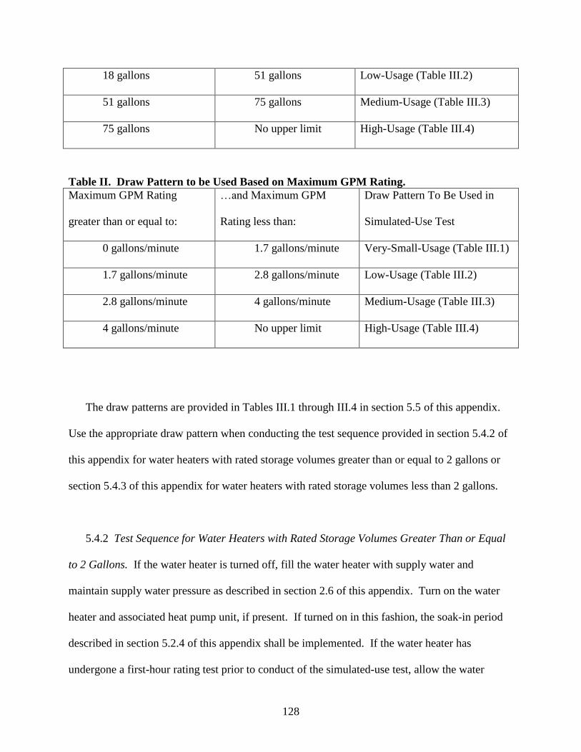
128
18 gallons 51 gallons Low-Usage (Table III.2)
51 gallons 75 gallons Medium-Usage (Table III.3)
75 gallons No upper limit High-Usage (Table III.4)
Table II. Draw Pattern to be Used Based on Maximum GPM Rating.
Maximum GPM Rating
greater than or equal to:
…and Maximum GPM
Rating less than:
Draw Pattern To Be Used in
Simulated-Use Test
0 gallons/minute 1.7 gallons/minute Very-Small-Usage (Table III.1)
1.7 gallons/minute 2.8 gallons/minute Low-Usage (Table III.2)
2.8 gallons/minute 4 gallons/minute Medium-Usage (Table III.3)
4 gallons/minute No upper limit High-Usage (Table III.4)
The draw patterns are provided in Tables III.1 through III.4 in section 5.5 of this appendix.
Use the appropriate draw pattern when conducting the test sequence provided in section 5.4.2 of
this appendix for water heaters with rated storage volumes greater than or equal to 2 gallons or
section 5.4.3 of this appendix for water heaters with rated storage volumes less than 2 gallons.
5.4.2 Test Sequence for Water Heaters with Rated Storage Volumes Greater Than or Equal
to 2 Gallons. If the water heater is turned off, fill the water heater with supply water and
maintain supply water pressure as described in section 2.6 of this appendix. Turn on the water
heater and associated heat pump unit, if present. If turned on in this fashion, the soak-in period
described in section 5.2.4 of this appendix shall be implemented. If the water heater has
undergone a first-hour rating test prior to conduct of the simulated-use test, allow the water
129
heater to fully recover after completion of that test such that the main burner, heating elements,
or heat pump compressor of the water heater are no longer raising the temperature of the stored
water. In all cases, the water heater shall sit idle for 1 hour prior to the start of the 24-hour test;
during which time no water is drawn from the unit and there is no energy input to the main
heating elements, heat pump compressor, and/or burners. At the end of this period, the 24-hour
simulated-use test will begin.
At the start of the 24-hour test, record the mean tank temperature ( 0), and the electrical
and/or fuel measurement readings, as appropriate. Begin the 24-hour simulated use test by
withdrawing the volume specified in the appropriate table in section 5.5 of this appendix (i.e.,
Table III.1, Table III.2, Table III.3, or Table III.4, depending on the first-hour rating or
maximum GPM rating) for the first draw at the flow rate specified in the applicable table.
Record the time when this first draw is initiated and assign it as the test elapsed time () of zero
(0). Record the average storage tank and ambient temperature every minute throughout the 24-
hour simulated-use test. At the elapsed times specified in the applicable draw pattern table in
section 5.5 of this appendix for a particular draw pattern, initiate additional draws pursuant to the
draw pattern, removing the volume of hot water at the prescribed flow rate specified by the table.
The maximum allowable deviation from the specified volume of water removed for any single
draw taken at a nominal flow rate of 1 GPM or 1.7 GPM is ±0.1 gallons (±0.4 liters). The
maximum allowable deviation from the specified volume of water removed for any single draw
taken at a nominal flow rate of 3 GPM is ±0.25 gallons (0.9 liters). The quantity of water
withdrawn during the last draw shall be increased or decreased as necessary such that the total
volume of water withdrawn equals the prescribed daily amount for that draw pattern ±1.0 gallon
130
(±3.8 liters). If this adjustment to the volume drawn during the last draw results in no draw
taking place, the test is considered invalid.
All draws during the 24-hour simulated-use test shall be made at the flow rates specified in
the applicable draw pattern table in section 5.5 of this appendix, within a tolerance of ± 0.25
gallons per minute (±0. 9 liters per minute). Measurements of the inlet and outlet temperatures
shall be made 5 seconds after the draw is initiated and at every subsequent 3-second interval
throughout the duration of each draw. Calculate and record the mean of the hot water discharge
temperature and the cold water inlet temperature for each draw ( del,i and in,i). Determine and
record the net mass or volume removed (Mi or Vi), as appropriate, after each draw.
At the end of the first recovery period following the first draw, which may extend beyond
subsequent draws, record the maximum mean tank temperature observed after cut-out, max,1,
and the energy consumed by an electric resistance, gas, or oil-fired water heater (including
electrical energy), from the beginning of the test, Qr. For heat pump water heaters, the total
energy consumed during the first recovery by the heat pump (including compressor, fan,
controls, pump, etc.) and, if applicable, by the resistive element(s) shall be recorded as Qr.
The start of the portion of the test during which the standby loss coefficient is determined
depends upon whether the unit has fully recovered from the first draw cluster. If a recovery is
occurring at or within five minutes of the end of the final draw in the first draw cluster, as
identified in the applicable draw pattern table in section 5.5 of this appendix, then the standby
period starts when a maximum average tank temperature is observed starting five minutes after
131
the end of the recovery period that follows that draw. If a recovery does not occur at or within
five minutes of the end of the final draw in the first draw cluster, as identified in the applicable
draw pattern table in section 5.5 of this appendix, then the standby period starts five minutes
after the end of that draw. Determine and record the total electrical energy and/or fossil fuel
consumed from the beginning of the test to the start of the standby period, Qsu,0.
In preparation for determining the energy consumed during standby, record the reading given
on the electrical energy (watt-hour) meter, the gas meter, and/or the scale used to determine oil
consumption, as appropriate. Record the mean tank temperature at the start of the standby period
as su,0. At 1-minute intervals, record the mean tank temperature and the electric and/or fuel
instrument readings until the next draw is initiated. Just prior to initiation of the next draw,
record the mean tank temperature as su,f. If the water heater is undergoing recovery when the
next draw is initiated, record the mean tank temperature su,f at the minute prior to the start of
the recovery. The time at which this value occurs is the end of the standby period. Determine
the total electrical energy and/or fossil fuel energy consumption from the beginning of the test to
this time and record as Qsu,f. Record the time interval between the start of the standby period and
the end of the standby period as stby,1. Record the time during which water is not being
withdrawn from the water heater during the entire 24-hour period as stby,2.
In the event that the recovery period continues from the end of the last draw of the first draw
cluster until the subsequent draw, the standby period will start after the end of the first recovery
period after the last draw of the simulated-use test, when the temperature reaches the maximum
average tank temperature, though no sooner than five minutes after the end of this recovery
period. The standby period shall last eight hours, so testing will extend beyond the 24-hour
duration of the simulated-use test. Determine and record the total electrical energy and/or fossil
132
fuel consumed from the beginning of the simulated-use test to the start of the 8-hour standby
period, Qsu,0. In preparation for determining the energy consumed during standby, record the
reading(s) given on the electrical energy (watt-hour) meter, the gas meter, and/or the scale used
to determine oil consumption, as appropriate. Record the mean tank temperature at the start of
the standby period as su,0. Record the mean tank temperature, the ambient temperature, and the
electric and/or fuel instrument readings until the end of the 8 hour period. Record the mean tank
temperature at the end of the 8 hour standby period as su,f. If the water heater is undergoing
recovery at the end of the standby period, record the mean tank temperature su,f at the minute
prior to the start of the recovery, which will mark the end of the standby period. Determine the
total electrical energy and/or fossil fuel energy consumption from the beginning of the test to the
end of the standby period and record this value as Qsu,f. Record the time interval between the
start of the standby period and the end of the standby period as stby,1.
Following the final draw of the prescribed draw pattern and subsequent recovery, allow the
water heater to remain in the standby mode until exactly 24 hours have elapsed since the start of
the simulated-use test (i.e., since = 0). During the last hour of the simulated-use test, power to
the main burner, heating element, or compressor shall be disabled. At 24 hours, record the
reading given by the gas meter, oil meter, and/or the electrical energy meter as appropriate.
Determine the fossil fuel and/or electrical energy consumed during the entire 24-hour simulated-
use test and designate the quantity as Q.
5.4.3 Test Sequence for Water Heaters with Rated Storage Volume Less than 2 Gallons.
Establish normal operation with the discharge water temperature at 125°F ± 5°F (51.7°C ±
2.8°C) and set the flow rate as determined in section 5.2 of this appendix. Prior to

133
commencement of the 24-hour simulated-use test, the unit shall remain in an idle state in which
controls are active but no water is drawn through the unit for a period of one hour. With no draw
occurring, record the reading given by the gas meter and/or the electrical energy meter as
appropriate. Begin the 24-hour simulated-use test by withdrawing the volume specified in
Tables III.1 through III.4 of section 5.5 of this appendix for the first draw at the flow rate
specified. Record the time when this first draw is initiated and designate it as an elapsed time, ,
of 0. At the elapsed times specified in Tables III.1 through III.4 for a particular draw pattern,
initiate additional draws, removing the volume of hot water at the prescribed flow rate specified
in Tables III.1 through III.4. The maximum allowable deviation from the specified volume of
water removed for any single draw taken at a nominal flow rate less than or equal to 1.7 GPM
(6.4 L/min) is ±0.1 gallons (±0.4 liters). The maximum allowable deviation from the specified
volume of water removed for any single draw taken at a nominal flow rate of 3 GPM (11.4
L/min) is ±0.25 gallons (0.9 liters). The quantity of water drawn during the final draw shall be
increased or decreased as necessary such that the total volume of water withdrawn equals the
prescribed daily amount for that draw pattern ±1.0 gallon (±3.8 liters). If this adjustment to the
volume drawn in the last draw results in no draw taking place, the test is considered invalid.
Measurements of the inlet and outlet water temperatures shall be made 5 seconds after the
draw is initiated and at every 3-second interval thereafter throughout the duration of the draw.
Calculate the mean of the hot water discharge temperature and the cold water inlet temperature
for each draw. Record the mass of the withdrawn water or the water meter reading, as
appropriate, after each draw. At the end of the recovery period following the first draw,
determine and record the fossil fuel and/or electrical energy consumed, Qr. Following the final
134
draw and subsequent recovery, allow the water heater to remain in the standby mode until
exactly 24 hours have elapsed since the start of the test (i.e., since = 0). At 24 hours, record the
reading given by the gas meter, oil meter, and/or the electrical energy meter, as appropriate.
Determine the fossil fuel and/or electrical energy consumed during the entire 24-hour simulated-
use test and designate the quantity as Q.
5.5 Draw Patterns. The draw patterns to be imposed during 24-hour simulated-use tests are
provided in Tables III.1 through III.4. Subject each water heater under test to one of these draw
patterns based on its first-hour rating or maximum GPM rating, as discussed in section 5.4.1 of
this appendix. Each draw pattern specifies the elapsed time in hours and minutes during the 24-
hour test when a draw is to commence, the total volume of water in gallons (liters) that is to be
removed during each draw, and the flow rate at which each draw is to be taken, in gallons (liters)
per minute.

135
Table III.1 Very-Small-Usage Draw Pattern
Draw Number Time During Test
[hh:mm]
Volume
[gallons (L)]
Flow Rate**
[GPM (L/min)]
1* 0:00 2.0 (7.6) 1 (3.8)
2* 1:00 1.0 (3.8) 1 (3.8)
3* 1:05 0.5 (1.9) 1 (3.8)
4* 1:10 0.5 (1.9) 1 (3.8)
5* 1:15 0.5 (1.9) 1 (3.8)
6 8:00 1.0 (3.8) 1 (3.8)
7 8:15 2.0 (7.6) 1 (3.8)
8 9:00 1.5 (5.7) 1 (3.8)
9 9:15 1.0 (3.8) 1 (3.8)
Total Volume Drawn Per Day: 10 gallons (38 L)
* Denotes draws in first draw cluster.
** Should the water heater have a maximum GPM rating less than 1 GPM (3.8 L/min), then all
draws shall be implemented at a flow rate equal to the rated maximum GPM.
Table III.2 Low-Usage Draw Pattern
Draw Number Time During Test
[hh:mm]
Volume
[gallons
(liters)]
Flow Rate
[GPM (L/min)]
1* 0:00 15.0 (56.8) 1.7 (6.4)
2* 0:30 2.0 (7.6) 1 (3.8)
3* 1:00 1.0 (3.8) 1 (3.8)
4 10:30 6.0 (22.7) 1.7 (6.4)
5 11:30 4.0 (15.1) 1.7 (6.4)
6 12:00 1.0 (3.8) 1 (3.8)
7 12:45 1.0 (3.8) 1 (3.8)
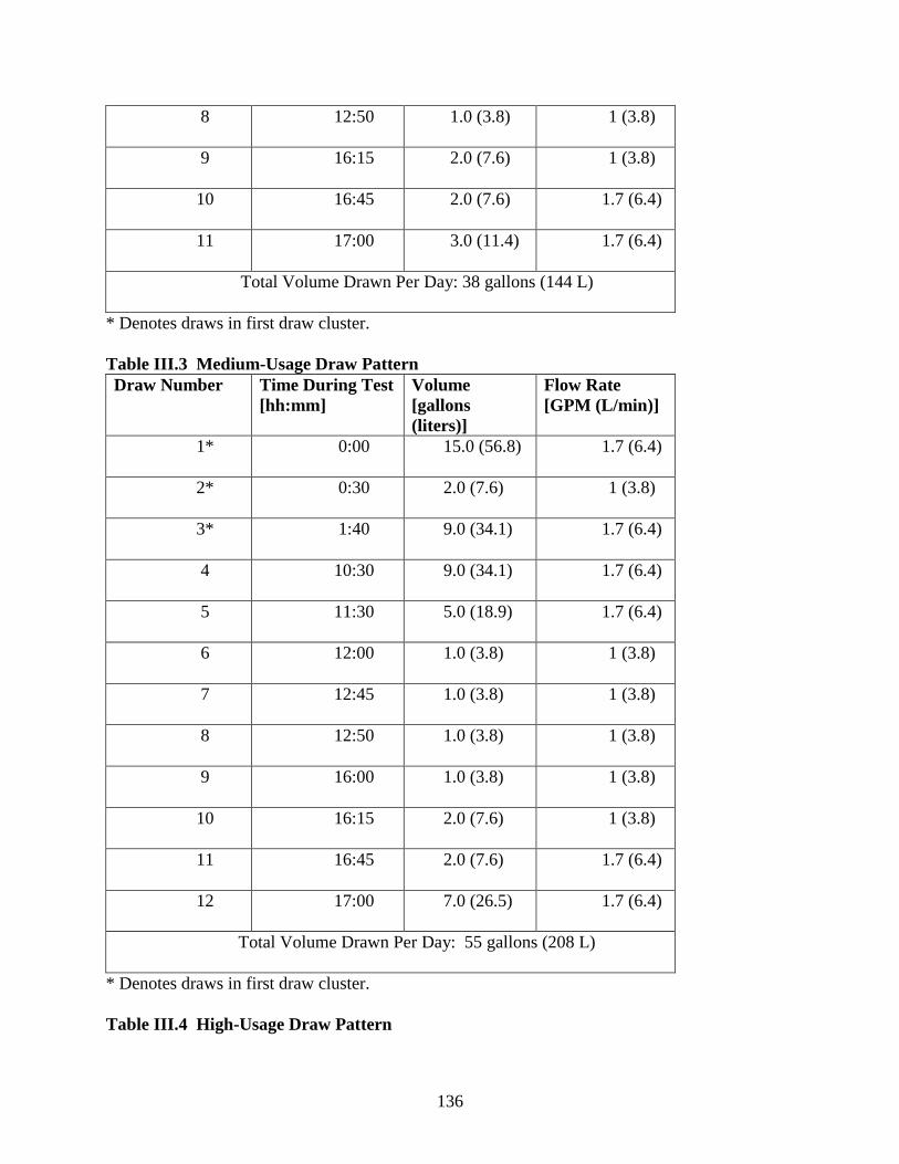
136
8 12:50 1.0 (3.8) 1 (3.8)
9 16:15 2.0 (7.6) 1 (3.8)
10 16:45 2.0 (7.6) 1.7 (6.4)
11 17:00 3.0 (11.4) 1.7 (6.4)
Total Volume Drawn Per Day: 38 gallons (144 L)
* Denotes draws in first draw cluster.
Table III.3 Medium-Usage Draw Pattern
Draw Number Time During Test
[hh:mm]
Volume
[gallons
(liters)]
Flow Rate
[GPM (L/min)]
1* 0:00 15.0 (56.8) 1.7 (6.4)
2* 0:30 2.0 (7.6) 1 (3.8)
3* 1:40 9.0 (34.1) 1.7 (6.4)
4 10:30 9.0 (34.1) 1.7 (6.4)
5 11:30 5.0 (18.9) 1.7 (6.4)
6 12:00 1.0 (3.8) 1 (3.8)
7 12:45 1.0 (3.8) 1 (3.8)
8 12:50 1.0 (3.8) 1 (3.8)
9 16:00 1.0 (3.8) 1 (3.8)
10 16:15 2.0 (7.6) 1 (3.8)
11 16:45 2.0 (7.6) 1.7 (6.4)
12 17:00 7.0 (26.5) 1.7 (6.4)
Total Volume Drawn Per Day: 55 gallons (208 L)
* Denotes draws in first draw cluster.
Table III.4 High-Usage Draw Pattern
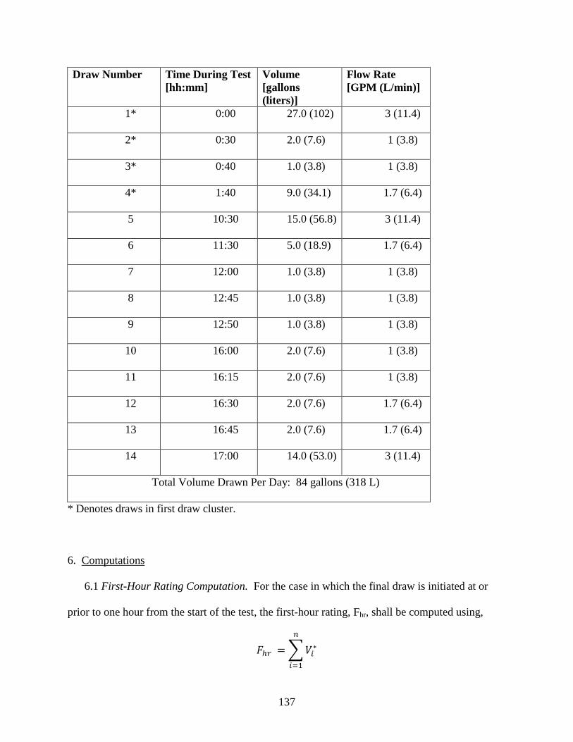
137
Draw Number Time During Test
[hh:mm]
Volume
[gallons
(liters)]
Flow Rate
[GPM (L/min)]
1* 0:00 27.0 (102) 3 (11.4)
2* 0:30 2.0 (7.6) 1 (3.8)
3* 0:40 1.0 (3.8) 1 (3.8)
4* 1:40 9.0 (34.1) 1.7 (6.4)
5 10:30 15.0 (56.8) 3 (11.4)
6 11:30 5.0 (18.9) 1.7 (6.4)
7 12:00 1.0 (3.8) 1 (3.8)
8 12:45 1.0 (3.8) 1 (3.8)
9 12:50 1.0 (3.8) 1 (3.8)
10 16:00 2.0 (7.6) 1 (3.8)
11 16:15 2.0 (7.6) 1 (3.8)
12 16:30 2.0 (7.6) 1.7 (6.4)
13 16:45 2.0 (7.6) 1.7 (6.4)
14 17:00 14.0 (53.0) 3 (11.4)
Total Volume Drawn Per Day: 84 gallons (318 L)
* Denotes draws in first draw cluster.
6. Computations
6.1 First-Hour Rating Computation. For the case in which the final draw is initiated at or
prior to one hour from the start of the test, the first-hour rating, Fhr, shall be computed using,
∑
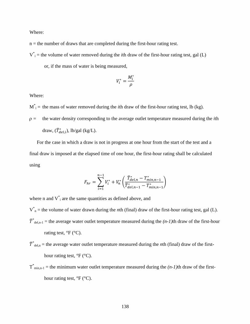
138
Where:
n = the number of draws that are completed during the first-hour rating test.
V*i = the volume of water removed during the ith draw of the first-hour rating test, gal (L)
or, if the mass of water is being measured,
Where:
M*i = the mass of water removed during the ith draw of the first-hour rating test, lb (kg).
= the water density corresponding to the average outlet temperature measured during the ith
draw, ( ), lb/gal (kg/L).
For the case in which a draw is not in progress at one hour from the start of the test and a
final draw is imposed at the elapsed time of one hour, the first-hour rating shall be calculated
using
∑
(
)
where n and V*i are the same quantities as defined above, and
V*n = the volume of water drawn during the nth (final) draw of the first-hour rating test, gal (L).
*del,n-1 = the average water outlet temperature measured during the (n-1)th draw of the first-hour
rating test, °F (°C).
*del,n = the average water outlet temperature measured during the nth (final) draw of the first-
hour rating test, °F (°C).
T*min,n-1 = the minimum water outlet temperature measured during the (n-1)th draw of the first-
hour rating test, °F (°C).
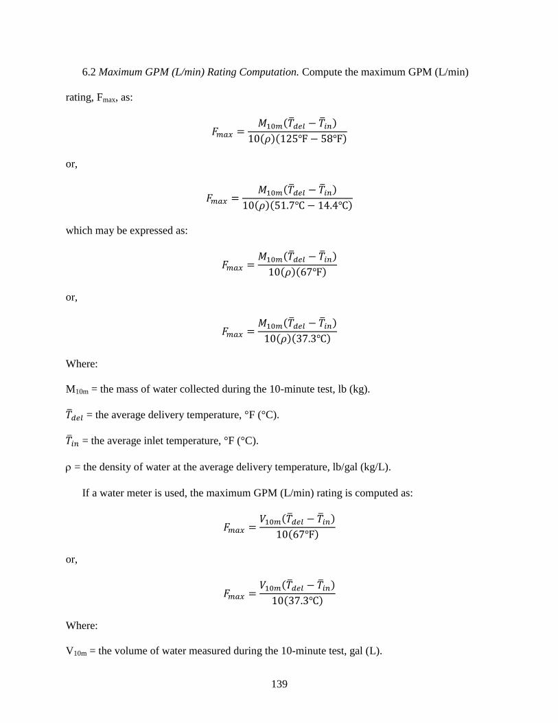
139
6.2 Maximum GPM (L/min) Rating Computation. Compute the maximum GPM (L/min)
rating, Fmax, as:
( )
( )( )
or,
( )
( )( )
which may be expressed as:
( )
( )( )
or,
( )
( )( )
Where:
M10m = the mass of water collected during the 10-minute test, lb (kg).
= the average delivery temperature, °F (°C).
= the average inlet temperature, °F (°C).
= the density of water at the average delivery temperature, lb/gal (kg/L).
If a water meter is used, the maximum GPM (L/min) rating is computed as:
( )
( )
or,
( )
( )
Where:
V10m = the volume of water measured during the 10-minute test, gal (L).
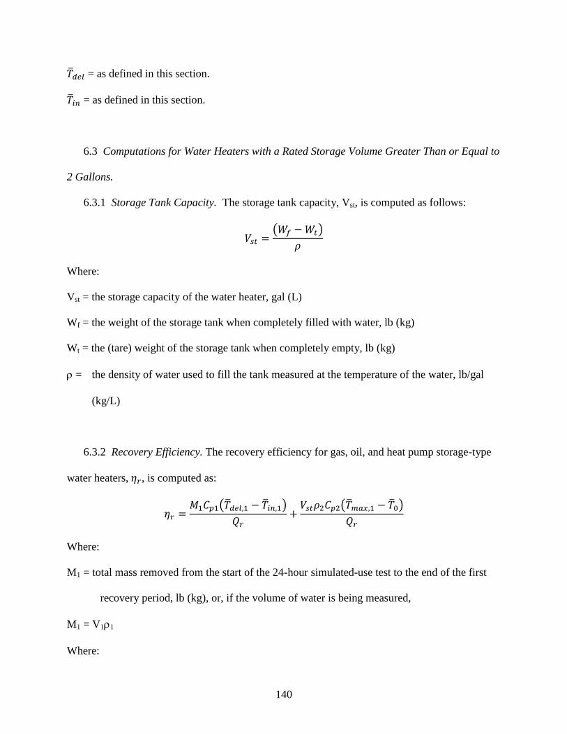
140
= as defined in this section.
= as defined in this section.
6.3 Computations for Water Heaters with a Rated Storage Volume Greater Than or Equal to
2 Gallons.
6.3.1 Storage Tank Capacity. The storage tank capacity, Vst, is computed as follows:
( )
Where:
Vst = the storage capacity of the water heater, gal (L)
Wf = the weight of the storage tank when completely filled with water, lb (kg)
Wt = the (tare) weight of the storage tank when completely empty, lb (kg)
= the density of water used to fill the tank measured at the temperature of the water, lb/gal
(kg/L)
6.3.2 Recovery Efficiency. The recovery efficiency for gas, oil, and heat pump storage-type
water heaters, , is computed as:
( )
( )
Where:
M1 = total mass removed from the start of the 24-hour simulated-use test to the end of the first
recovery period, lb (kg), or, if the volume of water is being measured,
M1 = V11
Where:
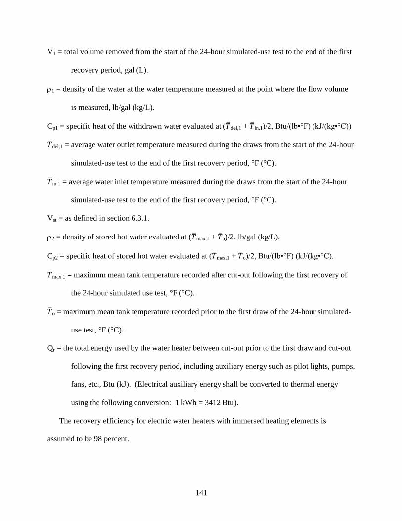
141
V1 = total volume removed from the start of the 24-hour simulated-use test to the end of the first
recovery period, gal (L).
1 = density of the water at the water temperature measured at the point where the flow volume
is measured, lb/gal (kg/L).
Cp1 = specific heat of the withdrawn water evaluated at ( del,1 + in,1)/2, Btu/(lb•°F) (kJ/(kg•°C))
del,1 = average water outlet temperature measured during the draws from the start of the 24-hour
simulated-use test to the end of the first recovery period, °F (°C).
in,1 = average water inlet temperature measured during the draws from the start of the 24-hour
simulated-use test to the end of the first recovery period, °F (°C).
Vst = as defined in section 6.3.1.
2 = density of stored hot water evaluated at ( max,1 + o)/2, lb/gal (kg/L).
Cp2 = specific heat of stored hot water evaluated at ( max,1 + o)/2, Btu/(lb•°F) (kJ/(kg•°C).
max,1 = maximum mean tank temperature recorded after cut-out following the first recovery of
the 24-hour simulated use test, °F (°C).
o = maximum mean tank temperature recorded prior to the first draw of the 24-hour simulated-
use test, °F (°C).
Qr = the total energy used by the water heater between cut-out prior to the first draw and cut-out
following the first recovery period, including auxiliary energy such as pilot lights, pumps,
fans, etc., Btu (kJ). (Electrical auxiliary energy shall be converted to thermal energy
using the following conversion: 1 kWh = 3412 Btu).
The recovery efficiency for electric water heaters with immersed heating elements is
assumed to be 98 percent.
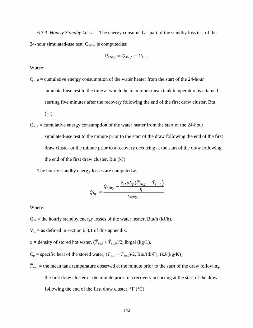
142
6.3.3 Hourly Standby Losses. The energy consumed as part of the standby loss test of the
24-hour simulated-use test, Qstby, is computed as:
Where:
Qsu,0 = cumulative energy consumption of the water heater from the start of the 24-hour
simulated-use test to the time at which the maximum mean tank temperature is attained
starting five minutes after the recovery following the end of the first draw cluster, Btu
(kJ).
Qsu,f = cumulative energy consumption of the water heater from the start of the 24-hour
simulated-use test to the minute prior to the start of the draw following the end of the first
draw cluster or the minute prior to a recovery occurring at the start of the draw following
the end of the first draw cluster, Btu (kJ).
The hourly standby energy losses are computed as:
( )
Where:
Qhr = the hourly standby energy losses of the water heater, Btu/h (kJ/h).
Vst = as defined in section 6.3.1 of this appendix.
= density of stored hot water, ( su,f + su,0)/2, lb/gal (kg/L).
Cp = specific heat of the stored water, ( su,f + su,0)/2, Btu/(lb•F), (kJ/(kg•K))
su,f = the mean tank temperature observed at the minute prior to the start of the draw following
the first draw cluster or the minute prior to a recovery occurring at the start of the draw
following the end of the first draw cluster, °F (°C).
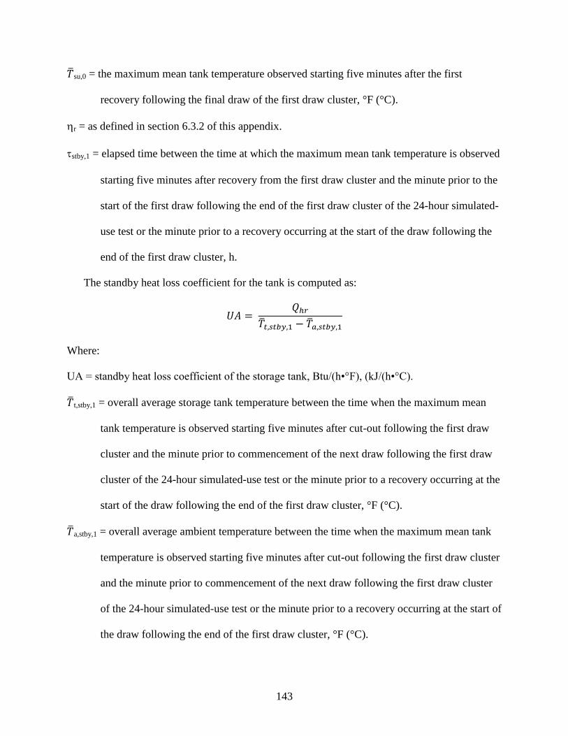
143
su,0 = the maximum mean tank temperature observed starting five minutes after the first
recovery following the final draw of the first draw cluster, °F (°C).
r = as defined in section 6.3.2 of this appendix.
stby,1 = elapsed time between the time at which the maximum mean tank temperature is observed
starting five minutes after recovery from the first draw cluster and the minute prior to the
start of the first draw following the end of the first draw cluster of the 24-hour simulated-
use test or the minute prior to a recovery occurring at the start of the draw following the
end of the first draw cluster, h.
The standby heat loss coefficient for the tank is computed as:
Where:
UA = standby heat loss coefficient of the storage tank, Btu/(h•°F), (kJ/(h•°C).
t,stby,1 = overall average storage tank temperature between the time when the maximum mean
tank temperature is observed starting five minutes after cut-out following the first draw
cluster and the minute prior to commencement of the next draw following the first draw
cluster of the 24-hour simulated-use test or the minute prior to a recovery occurring at the
start of the draw following the end of the first draw cluster, °F (°C).
a,stby,1 = overall average ambient temperature between the time when the maximum mean tank
temperature is observed starting five minutes after cut-out following the first draw cluster
and the minute prior to commencement of the next draw following the first draw cluster
of the 24-hour simulated-use test or the minute prior to a recovery occurring at the start of
the draw following the end of the first draw cluster, °F (°C).
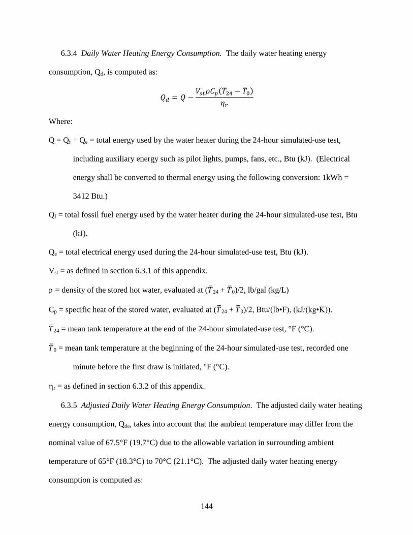
144
6.3.4 Daily Water Heating Energy Consumption. The daily water heating energy
consumption, Qd, is computed as:
( )
Where:
Q = Qf + Qe = total energy used by the water heater during the 24-hour simulated-use test,
including auxiliary energy such as pilot lights, pumps, fans, etc., Btu (kJ). (Electrical
energy shall be converted to thermal energy using the following conversion: 1kWh =
3412 Btu.)
Qf = total fossil fuel energy used by the water heater during the 24-hour simulated-use test, Btu
(kJ).
Qe = total electrical energy used during the 24-hour simulated-use test, Btu (kJ).
Vst = as defined in section 6.3.1 of this appendix.
= density of the stored hot water, evaluated at ( 24 + 0)/2, lb/gal (kg/L)
Cp = specific heat of the stored water, evaluated at ( 24 + 0)/2, Btu/(lb•F), (kJ/(kg•K)).
24 = mean tank temperature at the end of the 24-hour simulated-use test, °F (°C).
0 = mean tank temperature at the beginning of the 24-hour simulated-use test, recorded one
minute before the first draw is initiated, °F (°C).
r = as defined in section 6.3.2 of this appendix.
6.3.5 Adjusted Daily Water Heating Energy Consumption. The adjusted daily water heating
energy consumption, Qda, takes into account that the ambient temperature may differ from the
nominal value of 67.5°F (19.7°C) due to the allowable variation in surrounding ambient
temperature of 65°F (18.3°C) to 70°C (21.1°C). The adjusted daily water heating energy
consumption is computed as:
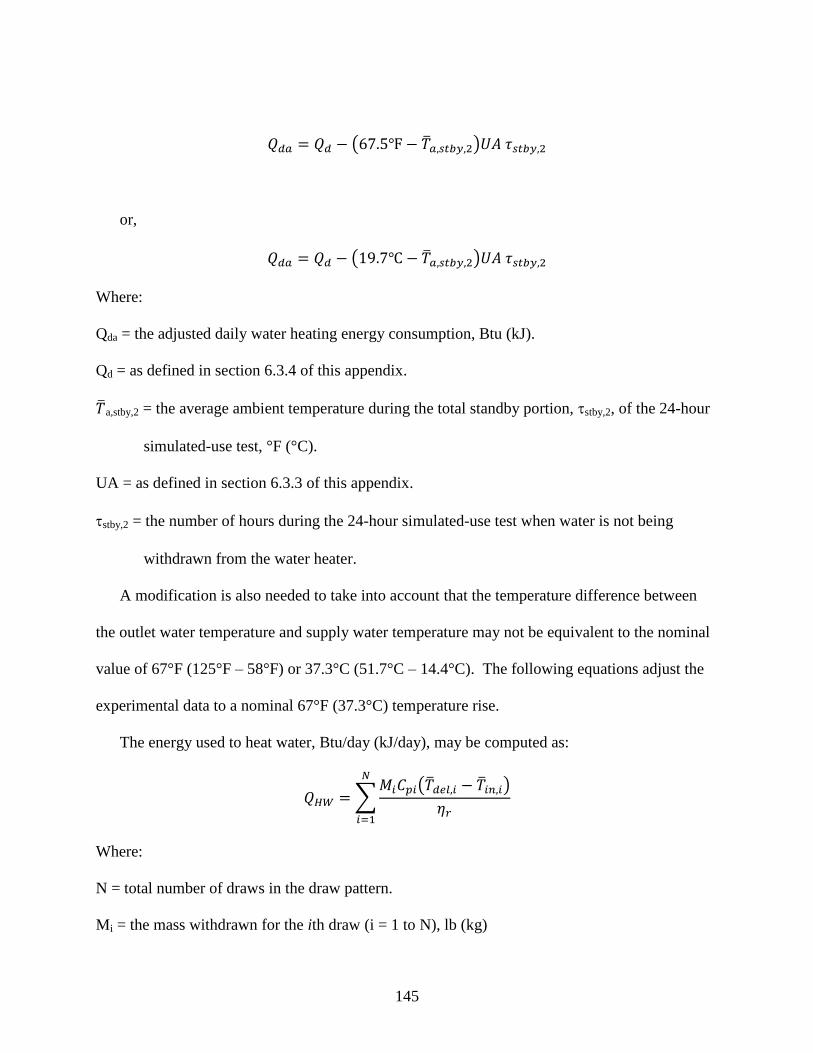
145
( )
or,
( )
Where:
Qda = the adjusted daily water heating energy consumption, Btu (kJ).
Qd = as defined in section 6.3.4 of this appendix.
a,stby,2 = the average ambient temperature during the total standby portion, stby,2, of the 24-hour
simulated-use test, °F (°C).
UA = as defined in section 6.3.3 of this appendix.
stby,2 = the number of hours during the 24-hour simulated-use test when water is not being
withdrawn from the water heater.
A modification is also needed to take into account that the temperature difference between
the outlet water temperature and supply water temperature may not be equivalent to the nominal
value of 67°F (125°F – 58°F) or 37.3°C (51.7°C – 14.4°C). The following equations adjust the
experimental data to a nominal 67°F (37.3°C) temperature rise.
The energy used to heat water, Btu/day (kJ/day), may be computed as:
∑ ( )
Where:
N = total number of draws in the draw pattern.
Mi = the mass withdrawn for the ith draw (i = 1 to N), lb (kg)

146
Cpi = the specific heat of the water of the ith draw evaluated at ( del,i + in,i)/2, Btu/(lb•°F)
(kJ/(kg•°C)).
del,i = the average water outlet temperature measured during the ith draw (i = 1 to N), °F (°C).
in,i = the average water inlet temperature measured during the ith draw (i = 1 to N), °F (°C).
r = as defined in section 6.3.2 of this appendix.
The energy required to heat the same quantity of water over a 67°F (37.3°C) temperature
rise, Btu/day (kJ/day), is:
∑ ( )
or
∑ ( )
The difference between these two values is:
QHWD = QHW,67°F – QHW
or QHWD = QHW,37.3°C – QHW
This difference (QHWD) must be added to the adjusted daily water heating energy consumption
value. Thus, the daily energy consumption value which takes into account that the ambient
temperature may not be 67.5°F (19.7°C) and that the temperature rise across the storage tank
may not be 67°F (37.3°C) is:
Qdm = Qda + QHWD
6.3.6 Uniform Energy Factor. The uniform energy factor, UEF, is computed as:
∑ ( )
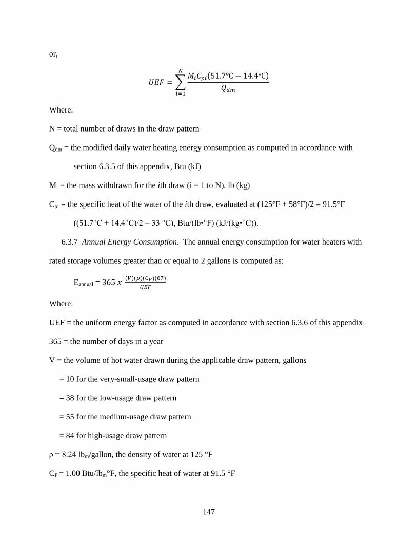
147
or,
∑ ( )
Where:
N = total number of draws in the draw pattern
Qdm = the modified daily water heating energy consumption as computed in accordance with
section 6.3.5 of this appendix, Btu (kJ)
Mi = the mass withdrawn for the ith draw (i = 1 to N), lb (kg)
Cpi = the specific heat of the water of the ith draw, evaluated at (125°F + 58°F)/2 = 91.5°F
((51.7°C + 14.4°C)/2 = 33 °C), Btu/(lb•°F) (kJ/(kg•°C)).
6.3.7 Annual Energy Consumption. The annual energy consumption for water heaters with
rated storage volumes greater than or equal to 2 gallons is computed as:
Eannual = ( )( )( )( )
Where:
UEF = the uniform energy factor as computed in accordance with section 6.3.6 of this appendix
365 = the number of days in a year
V = the volume of hot water drawn during the applicable draw pattern, gallons
= 10 for the very-small-usage draw pattern
= 38 for the low-usage draw pattern
= 55 for the medium-usage draw pattern
= 84 for high-usage draw pattern
ρ = 8.24 lbm/gallon, the density of water at 125 °F
CP = 1.00 Btu/lbm°F, the specific heat of water at 91.5 °F
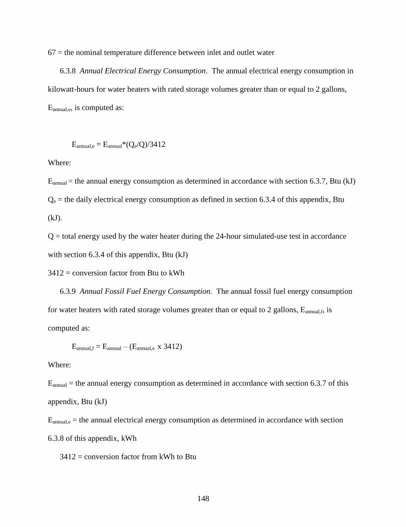
148
67 = the nominal temperature difference between inlet and outlet water
6.3.8 Annual Electrical Energy Consumption. The annual electrical energy consumption in
kilowatt-hours for water heaters with rated storage volumes greater than or equal to 2 gallons,
Eannual,e, is computed as:
Eannual,e = Eannual*(Qe/Q)/3412
Where:
Eannual = the annual energy consumption as determined in accordance with section 6.3.7, Btu (kJ)
Qe = the daily electrical energy consumption as defined in section 6.3.4 of this appendix, Btu
(kJ).
Q = total energy used by the water heater during the 24-hour simulated-use test in accordance
with section 6.3.4 of this appendix, Btu (kJ)
3412 = conversion factor from Btu to kWh
6.3.9 Annual Fossil Fuel Energy Consumption. The annual fossil fuel energy consumption
for water heaters with rated storage volumes greater than or equal to 2 gallons, Eannual,f, is
computed as:
Eannual,f = Eannual – (Eannual,e x 3412)
Where:
Eannual = the annual energy consumption as determined in accordance with section 6.3.7 of this
appendix, Btu (kJ)
Eannual,e = the annual electrical energy consumption as determined in accordance with section
6.3.8 of this appendix, kWh
3412 = conversion factor from kWh to Btu

149
6.4 Computations for Water Heaters With Rated Storage Volume Less Than 2 Gallons.
6.4.1 Recovery Efficiency. The recovery efficiency, , is computed as:
( )
Where:
M1 = total mass removed during the first draw of the 24-hour simulated-use test, lb (kg), or, if
the volume of water is being measured,
M1 = V1 •
Where:
V1 = total volume removed during the first draw of the 24-hour simulated-use test, gal (L).
= density of the water at the water temperature measured at the point where the flow volume is
measured, lb/gal (kg/L).
Cp1 = specific heat of the withdrawn water, ( )/2, Btu/(lb•°F) (kJ/(kg•°C)).
= average water outlet temperature measured during the first draw of the 24-hour
simulated-use test, °F (°C).
= average water inlet temperature measured during the first draw of the 24-hour simulated-
use test, °F (°C).
Qr = the total energy used by the water heater between cut-out prior to the first draw and cut-out
following the first draw, including auxiliary energy such as pilot lights, pumps, fans, etc.,
Btu (kJ). (Electrical auxiliary energy shall be converted to thermal energy using the
following conversion: 1 kWh = 3412 Btu.)
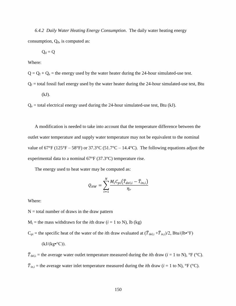
150
6.4.2 Daily Water Heating Energy Consumption. The daily water heating energy
consumption, Qd, is computed as:
Qd = Q
Where:
Q = Qf + Qe = the energy used by the water heater during the 24-hour simulated-use test.
Qf = total fossil fuel energy used by the water heater during the 24-hour simulated-use test, Btu
(kJ).
Qe = total electrical energy used during the 24-hour simulated-use test, Btu (kJ).
A modification is needed to take into account that the temperature difference between the
outlet water temperature and supply water temperature may not be equivalent to the nominal
value of 67°F (125°F – 58°F) or 37.3°C (51.7°C – 14.4°C). The following equations adjust the
experimental data to a nominal 67°F (37.3°C) temperature rise.
The energy used to heat water may be computed as:
∑ ( )
Where:
N = total number of draws in the draw pattern
Mi = the mass withdrawn for the ith draw (i = 1 to N), lb (kg)
Cpi = the specific heat of the water of the ith draw evaluated at ( del,i + in,i)/2, Btu/(lb•°F)
(kJ/(kg•°C)).
del,i = the average water outlet temperature measured during the ith draw (i = 1 to N), °F (°C).
in,i = the average water inlet temperature measured during the ith draw (i = 1 to N), °F (°C).
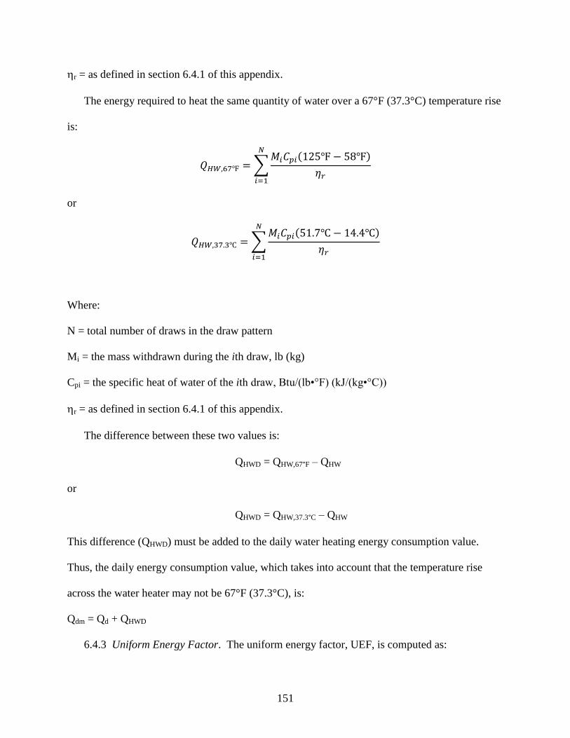
151
r = as defined in section 6.4.1 of this appendix.
The energy required to heat the same quantity of water over a 67°F (37.3°C) temperature rise
is:
∑ ( )
or
∑ ( )
Where:
N = total number of draws in the draw pattern
Mi = the mass withdrawn during the ith draw, lb (kg)
Cpi = the specific heat of water of the ith draw, Btu/(lb•°F) (kJ/(kg•°C))
r = as defined in section 6.4.1 of this appendix.
The difference between these two values is:
QHWD = QHW,67°F – QHW
or
QHWD = QHW,37.3°C – QHW
This difference (QHWD) must be added to the daily water heating energy consumption value.
Thus, the daily energy consumption value, which takes into account that the temperature rise
across the water heater may not be 67°F (37.3°C), is:
Qdm = Qd + QHWD
6.4.3 Uniform Energy Factor. The uniform energy factor, UEF, is computed as:
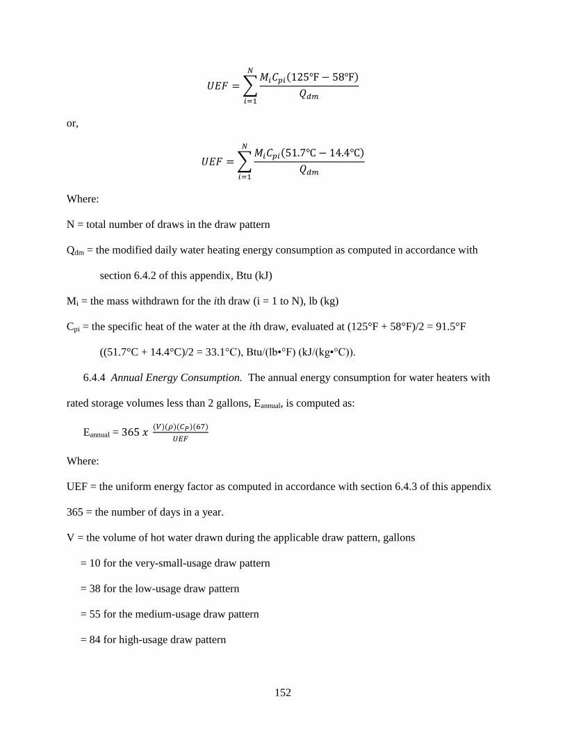
152
∑ ( )
or,
∑ ( )
Where:
N = total number of draws in the draw pattern
Qdm = the modified daily water heating energy consumption as computed in accordance with
section 6.4.2 of this appendix, Btu (kJ)
Mi = the mass withdrawn for the ith draw (i = 1 to N), lb (kg)
Cpi = the specific heat of the water at the ith draw, evaluated at (125°F + 58°F)/2 = 91.5°F
((51.7°C + 14.4°C)/2 = 33.1°C), Btu/(lb•°F) (kJ/(kg•°C)).
6.4.4 Annual Energy Consumption. The annual energy consumption for water heaters with
rated storage volumes less than 2 gallons, Eannual, is computed as:
Eannual = ( )( )( )( )
Where:
UEF = the uniform energy factor as computed in accordance with section 6.4.3 of this appendix
365 = the number of days in a year.
V = the volume of hot water drawn during the applicable draw pattern, gallons
= 10 for the very-small-usage draw pattern
= 38 for the low-usage draw pattern
= 55 for the medium-usage draw pattern
= 84 for high-usage draw pattern
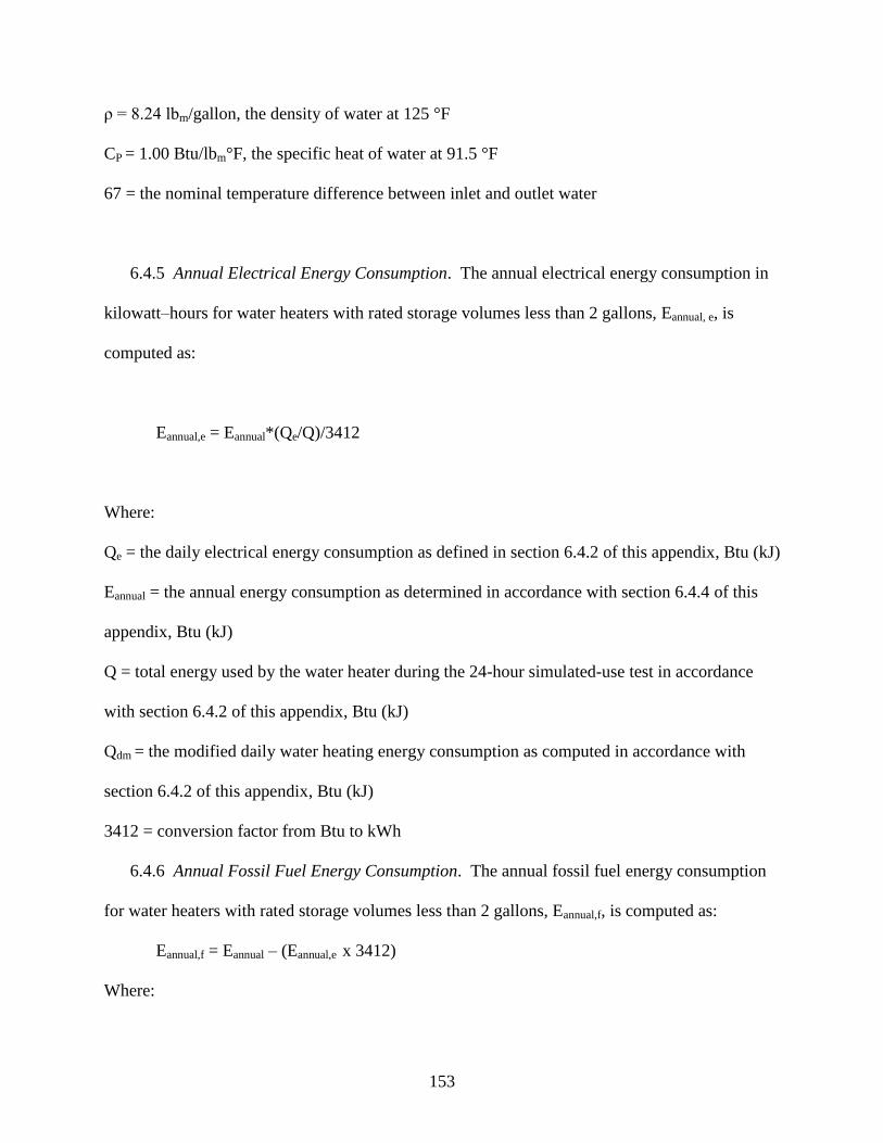
153
ρ = 8.24 lbm/gallon, the density of water at 125 °F
CP = 1.00 Btu/lbm°F, the specific heat of water at 91.5 °F
67 = the nominal temperature difference between inlet and outlet water
6.4.5 Annual Electrical Energy Consumption. The annual electrical energy consumption in
kilowatt–hours for water heaters with rated storage volumes less than 2 gallons, Eannual, e, is
computed as:
Eannual,e = Eannual*(Qe/Q)/3412
Where:
Qe = the daily electrical energy consumption as defined in section 6.4.2 of this appendix, Btu (kJ)
Eannual = the annual energy consumption as determined in accordance with section 6.4.4 of this
appendix, Btu (kJ)
Q = total energy used by the water heater during the 24-hour simulated-use test in accordance
with section 6.4.2 of this appendix, Btu (kJ)
Qdm = the modified daily water heating energy consumption as computed in accordance with
section 6.4.2 of this appendix, Btu (kJ)
3412 = conversion factor from Btu to kWh
6.4.6 Annual Fossil Fuel Energy Consumption. The annual fossil fuel energy consumption
for water heaters with rated storage volumes less than 2 gallons, Eannual,f, is computed as:
Eannual,f = Eannual – (Eannual,e x 3412)
Where:
154
Eannual,e = the annual electrical energy consumption as defined in section 6.4.5 of this appendix,
kWh.
Eannual = the annual energy consumption as defined in section 6.4.4 of this appendix, Btu (kJ)
3412 = conversion factor from kWh to Btu
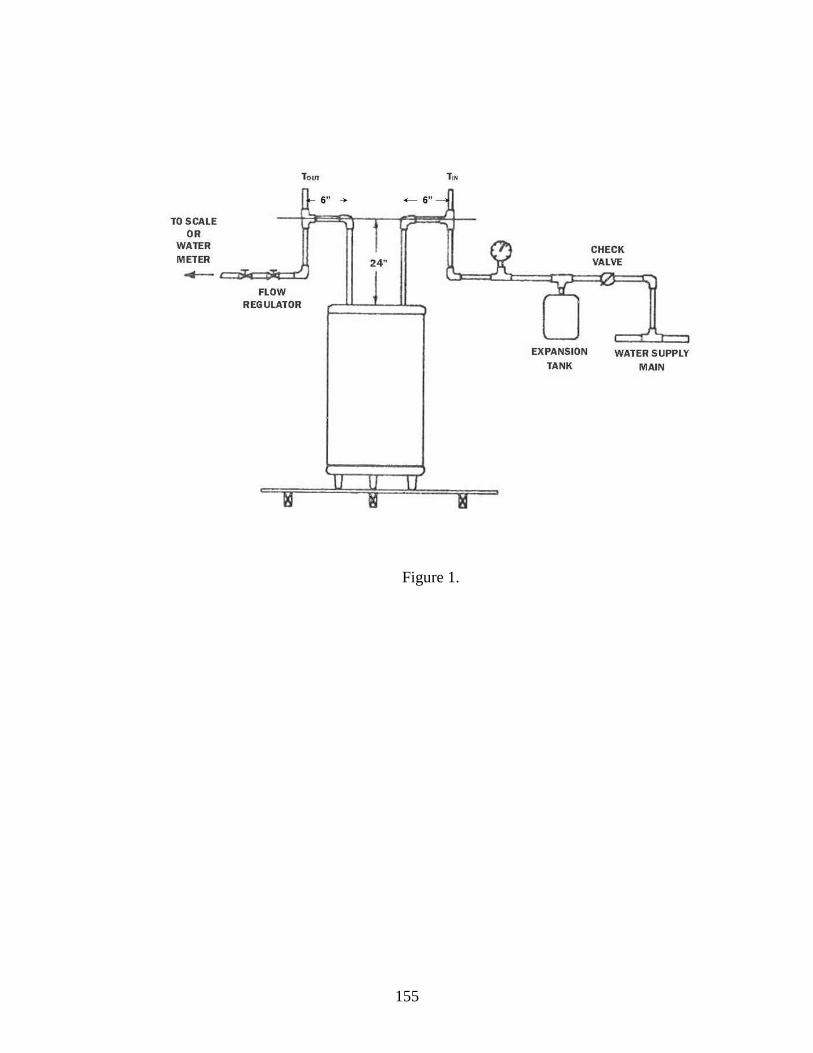
155
Figure 1.
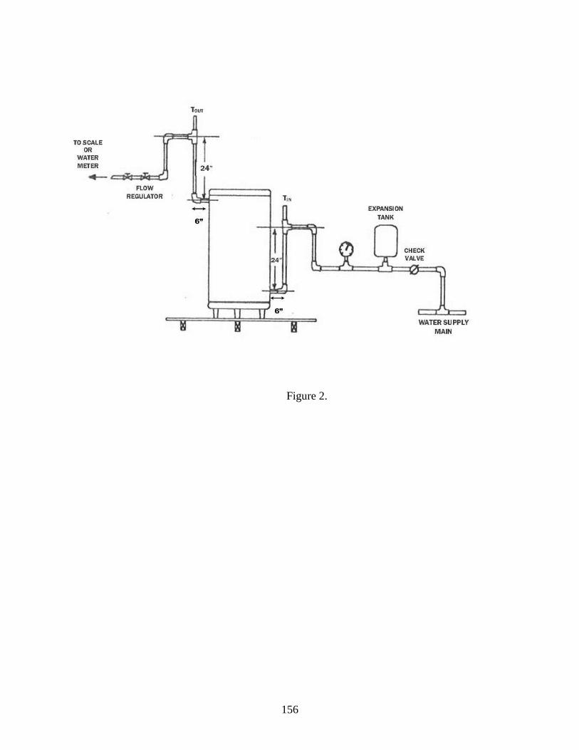
156
Figure 2.
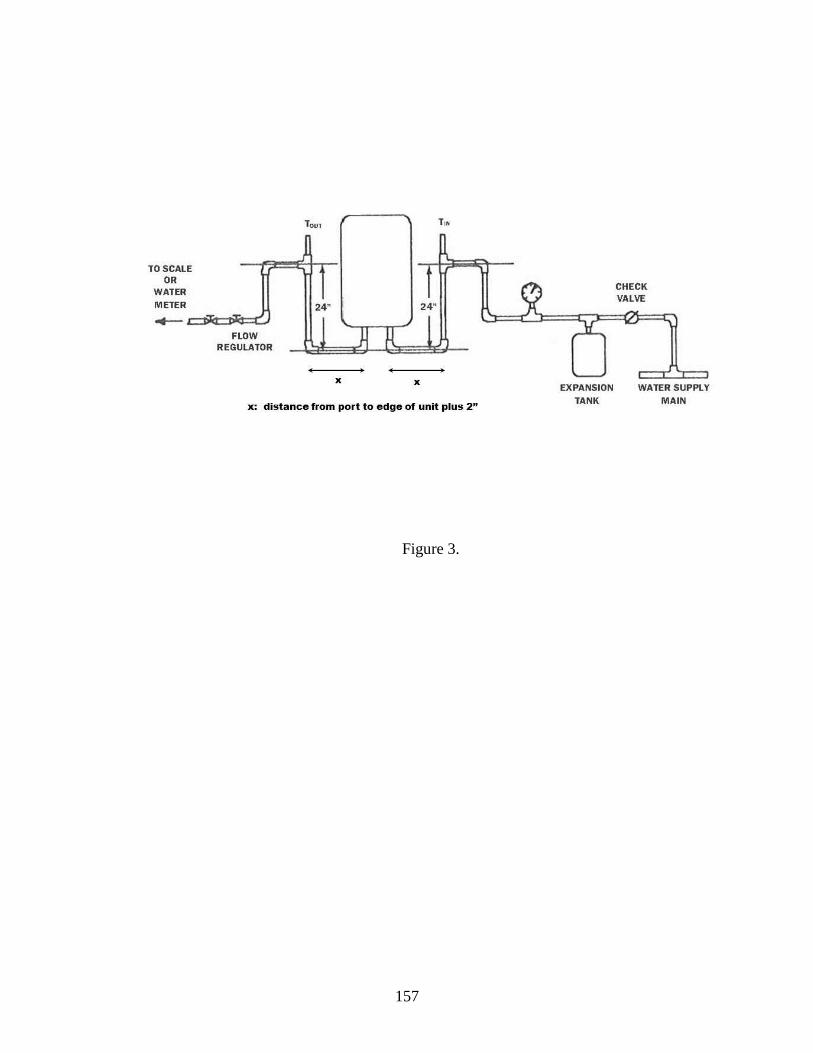
157
Figure 3.
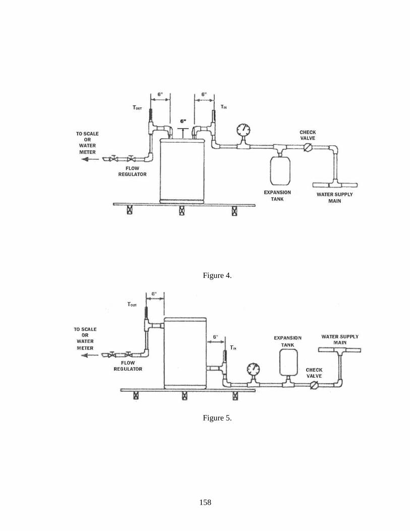
158
Figure 4.
Figure 5.
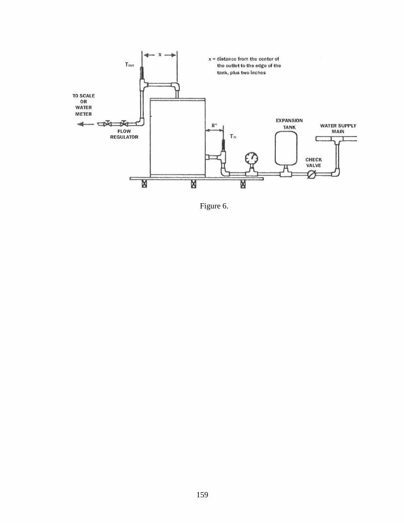
159
Figure 6.
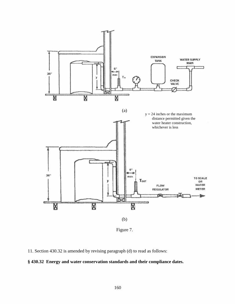
160
(a)
(b)
Figure 7.
11. Section 430.32 is amended by revising paragraph (d) to read as follows:
§ 430.32 Energy and water conservation standards and their compliance dates.
y = 24 inches or the maximum
distance permitted given the
water heater construction,
whichever is less
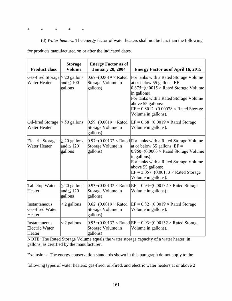
161
* * * * *
(d) Water heaters. The energy factor of water heaters shall not be less than the following
for products manufactured on or after the indicated dates.
Product class
Storage
Volume
Energy Factor as of
January 20, 2004 Energy Factor as of April 16, 2015
Gas-fired Storage
Water Heater
≥ 20 gallons
and ≤ 100
gallons
0.67−(0.0019 × Rated
Storage Volume in
gallons)
For tanks with a Rated Storage Volume
at or below 55 gallons: EF =
0.675−(0.0015 × Rated Storage Volume
in gallons).
For tanks with a Rated Storage Volume
above 55 gallons:
EF = 0.8012−(0.00078 × Rated Storage
Volume in gallons).
Oil-fired Storage
Water Heater
≤ 50 gallons 0.59−(0.0019 × Rated
Storage Volume in
gallons)
EF = 0.68−(0.0019 × Rated Storage
Volume in gallons).
Electric Storage
Water Heater
≥ 20 gallons
and ≤ 120
gallons
0.97−(0.00132 × Rated
Storage Volume in
gallons)
For tanks with a Rated Storage Volume
at or below 55 gallons: EF =
0.960−(0.0003 × Rated Storage Volume
in gallons).
For tanks with a Rated Storage Volume
above 55 gallons:
EF = 2.057−(0.00113 × Rated Storage
Volume in gallons).
Tabletop Water
Heater
≥ 20 gallons
and ≤ 120
gallons
0.93−(0.00132 × Rated
Storage Volume in
gallons)
EF = 0.93−(0.00132 × Rated Storage
Volume in gallons).
Instantaneous
Gas-fired Water
Heater
< 2 gallons 0.62−(0.0019 × Rated
Storage Volume in
gallons)
EF = 0.82−(0.0019 × Rated Storage
Volume in gallons).
Instantaneous
Electric Water
Heater
< 2 gallons 0.93−(0.00132 × Rated
Storage Volume in
gallons)
EF = 0.93−(0.00132 × Rated Storage
Volume in gallons).
NOTE: The Rated Storage Volume equals the water storage capacity of a water heater, in
gallons, as certified by the manufacturer.
Exclusions: The energy conservation standards shown in this paragraph do not apply to the
following types of water heaters: gas-fired, oil-fired, and electric water heaters at or above 2
162
gallons storage volume and below 20 gallons storage volume; gas-fired water heaters above 100
gallons storage volume; oil-fired water heaters above 50 gallons storage volume; electric water
heaters above 120 gallons storage volume; gas-fired instantaneous water heaters at or below
50,000 Btu/h.
* * * * *
PART 431 – ENERGY EFFICIENCY PROGRAM FOR CERTAIN COMMERCIAL AND
INDUSTRIAL EQUIPMENT
12. The authority citation for part 431 continues to read as follows:
Authority: 42 U.S.C. 6291-6317.
13. Section 431.102 is amended by adding the definition of “Residential-duty commercial water
heater,” in alphabetical order, to read as follows:
§431.102 Definitions concerning commercial water heaters, hot water supply boilers, and
unfired hot water storage tanks.
* * * * *
Residential-duty commercial water heater means any gas-fired, electric, or oil storage or
instantaneous commercial water heater that meets the following conditions:
(1) For models requiring electricity, uses single-phase external power supply;
(2) Is not designed to provide outlet hot water at temperatures greater than 180°F; and
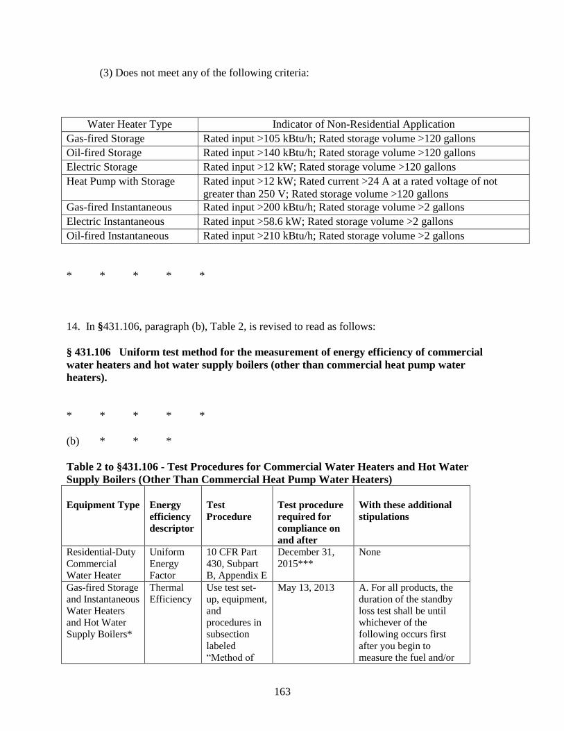
163
(3) Does not meet any of the following criteria:
Water Heater Type Indicator of Non-Residential Application
Gas-fired Storage Rated input >105 kBtu/h; Rated storage volume >120 gallons
Oil-fired Storage Rated input >140 kBtu/h; Rated storage volume >120 gallons
Electric Storage Rated input >12 kW; Rated storage volume >120 gallons
Heat Pump with Storage Rated input >12 kW; Rated current >24 A at a rated voltage of not
greater than 250 V; Rated storage volume >120 gallons
Gas-fired Instantaneous Rated input >200 kBtu/h; Rated storage volume >2 gallons
Electric Instantaneous Rated input >58.6 kW; Rated storage volume >2 gallons
Oil-fired Instantaneous Rated input >210 kBtu/h; Rated storage volume >2 gallons
* * * * *
14. In §431.106, paragraph (b), Table 2, is revised to read as follows:
§ 431.106 Uniform test method for the measurement of energy efficiency of commercial
water heaters and hot water supply boilers (other than commercial heat pump water
heaters).
* * * * *
(b) * * *
Table 2 to §431.106 - Test Procedures for Commercial Water Heaters and Hot Water
Supply Boilers (Other Than Commercial Heat Pump Water Heaters)
Equipment Type
Energy
efficiency
descriptor
Test
Procedure
Test procedure
required for
compliance on
and after
With these additional
stipulations
Residential-Duty
Commercial
Water Heater
Uniform
Energy
Factor
10 CFR Part
430, Subpart
B, Appendix E
December 31,
2015*** None
Gas-fired Storage
and Instantaneous
Water Heaters
and Hot Water
Supply Boilers*
Thermal
Efficiency Use test set-
up, equipment,
and
procedures in
subsection
labeled
“Method of
May 13, 2013 A. For all products, the
duration of the standby
loss test shall be until
whichever of the
following occurs first
after you begin to
measure the fuel and/or

164
Test” of ANSI
Z21.10.3-
2011**,
Exhibit G1
electric consumption: (1)
The first cut-out after 24
hours or (2) 48 hours, if
the water heater is not in
the heating mode at that
time. B. For oil and gas
products, the standby loss
in Btu per hour must be
calculated as follows: SL
(Btu per hour) = S (% per
hour) × 8.25 (Btu/gal-F)
× Measured Volume (gal)
× 70 (degrees F). C. For oil-fired products,
apply the following in
conducting the thermal
efficiency and standby
loss tests: (1) Venting
Requirements—Connect
a vertical length of flue
pipe to the flue gas outlet
of sufficient height so as
to meet the minimum
draft specified by the
manufacturer. (2) Oil
Supply—Adjust the
burner rate so that: (a)
The hourly Btu input rate
lies within ±2 percent of
the manufacturer's
specified input rate, (b)
the CO2 reading shows
the value specified by the
manufacturer, (c) smoke
in the flue does not
exceed No. 1 smoke as
measured by the
procedure in ASTM-
D2156-80 (reference for
guidance only, see
§431.104), and (d) fuel
pump pressure lies within
±10 percent of
manufacturer's
specifications. D. For electric products,
Standby
Loss Use test set-
up, equipment,
and
procedures in
subsection
labeled
“Method of
Test” of ANSI
Z21.10.3-
2011**,
Exhibit G2
May 13, 2013
Oil-fired Storage
and Instantaneous
Water Heaters
and Hot Water
Supply Boilers*
Thermal
Efficiency ANSI
Z21.10.3-
2011**,
Exhibit G1
May 13, 2013
Standby
Loss Use test set-
up, equipment,
and
procedures in
subsection
labeled
“Method of
Test” of ANSI
Z21.10.3-
2011**,
Exhibit G2
May 13, 2013
Electric Storage
and Instantaneous
Water Heaters
Standby
Loss Use test set-
up, equipment,
and
procedures in
subsection
labeled
“Method of
Test” of ANSI
Z21.10.3-
2011**,
Exhibit G2
May 13, 2013
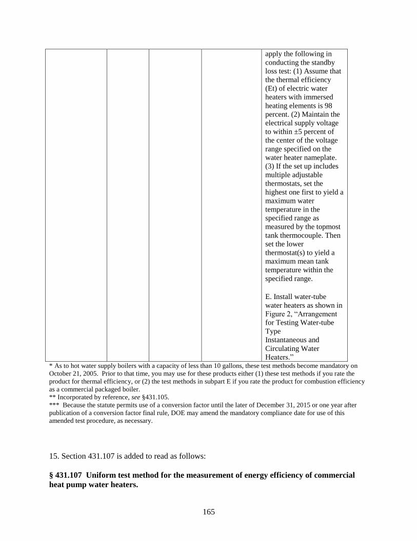
165
apply the following in
conducting the standby
loss test: (1) Assume that
the thermal efficiency
(Et) of electric water
heaters with immersed
heating elements is 98
percent. (2) Maintain the
electrical supply voltage
to within ±5 percent of
the center of the voltage
range specified on the
water heater nameplate. (3) If the set up includes
multiple adjustable
thermostats, set the
highest one first to yield a
maximum water
temperature in the
specified range as
measured by the topmost
tank thermocouple. Then
set the lower
thermostat(s) to yield a
maximum mean tank
temperature within the
specified range. E. Install water-tube
water heaters as shown in
Figure 2, “Arrangement
for Testing Water-tube
Type Instantaneous and
Circulating Water
Heaters.” * As to hot water supply boilers with a capacity of less than 10 gallons, these test methods become mandatory on
October 21, 2005. Prior to that time, you may use for these products either (1) these test methods if you rate the
product for thermal efficiency, or (2) the test methods in subpart E if you rate the product for combustion efficiency
as a commercial packaged boiler.
** Incorporated by reference, see §431.105.
*** Because the statute permits use of a conversion factor until the later of December 31, 2015 or one year after
publication of a conversion factor final rule, DOE may amend the mandatory compliance date for use of this
amended test procedure, as necessary.
15. Section 431.107 is added to read as follows:
§ 431.107 Uniform test method for the measurement of energy efficiency of commercial
heat pump water heaters.
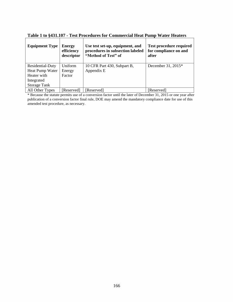
166
Table 1 to §431.107 - Test Procedures for Commercial Heat Pump Water Heaters
Equipment Type
Energy
efficiency
descriptor
Use test set-up, equipment, and
procedures in subsection labeled
“Method of Test” of
Test procedure required
for compliance on and
after
Residential-Duty
Heat Pump Water
Heater with
Integrated
Storage Tank
Uniform
Energy
Factor
10 CFR Part 430, Subpart B,
Appendix E December 31, 2015*
All Other Types [Reserved] [Reserved] [Reserved] * Because the statute permits use of a conversion factor until the later of December 31, 2015 or one year after
publication of a conversion factor final rule, DOE may amend the mandatory compliance date for use of this
amended test procedure, as necessary.
Recommended