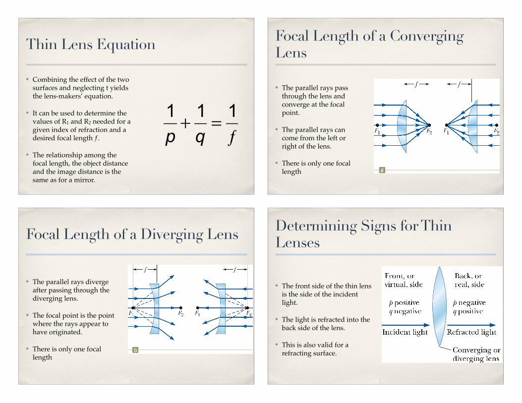
✤ Combining the effect of the two surfaces and neglecting t yields the lens-makers’ equation.
✤ It can be used to determine the values of R1 and R2 needed for a given index of refraction and a desired focal length ƒ.
✤ The relationship among the focal length, the object distance and the image distance is the same as for a mirror.
Thin Lens Equation
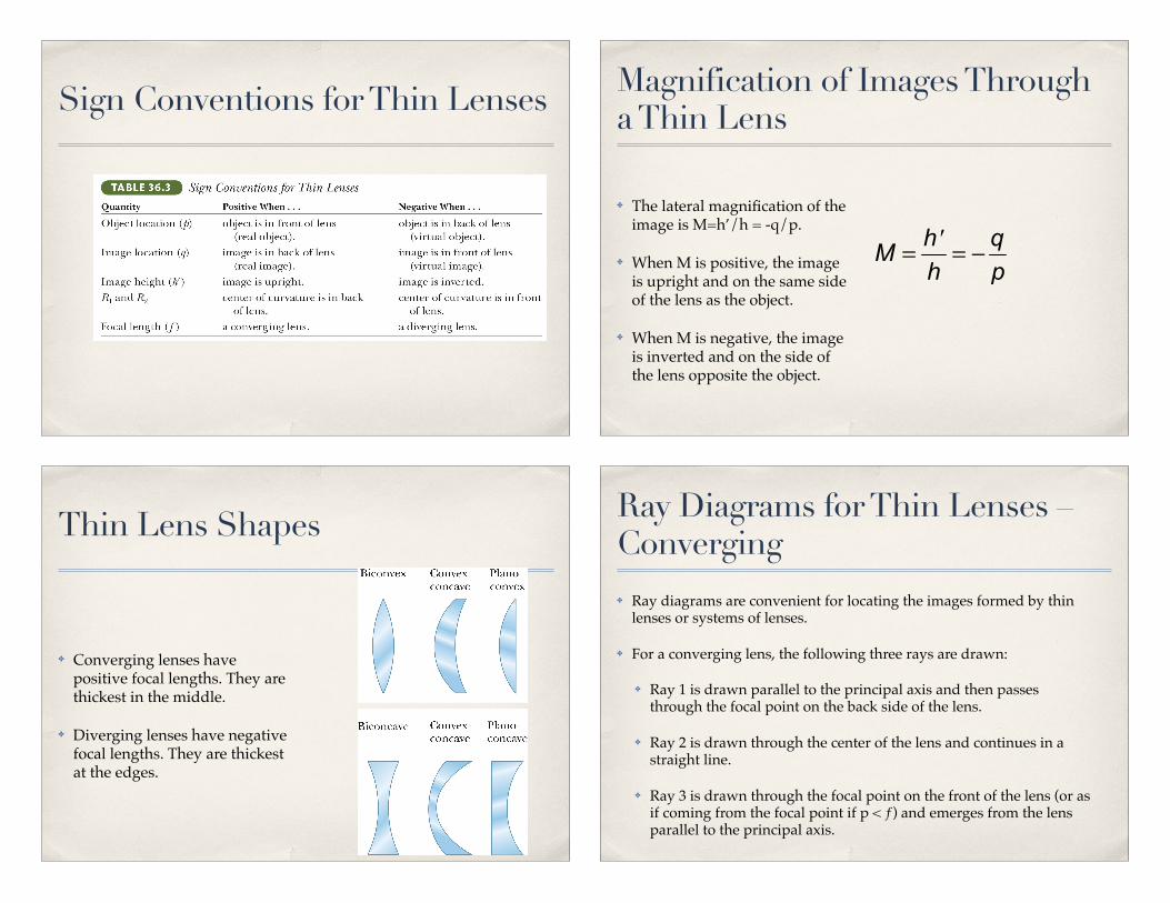
✤ The parallel rays pass through the lens and converge at the focal point.
✤ The parallel rays can come from the left or right of the lens.
✤ There is only one focal length
Focal Length of a Converging Lens
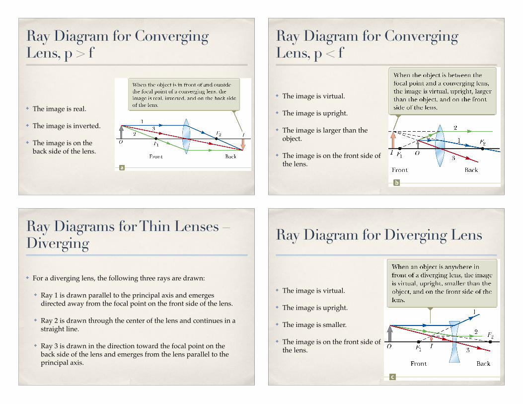
✤ The parallel rays diverge after passing through the diverging lens.
✤ The focal point is the point where the rays appear to have originated.
✤ There is only one focal length
Focal Length of a Diverging Lens
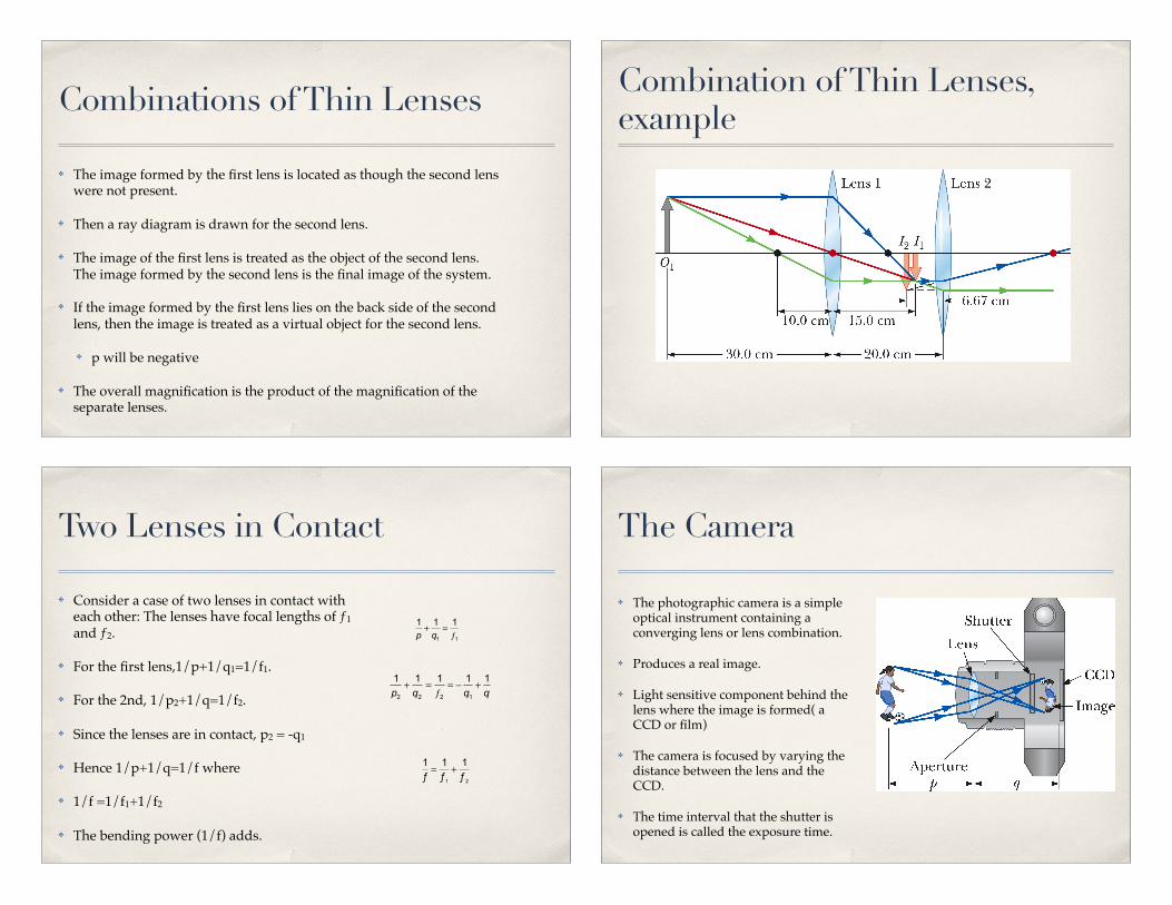
✤ The front side of the thin lens is the side of the incident light.
✤ The light is refracted into the back side of the lens.
✤ This is also valid for a refracting surface.
Determining Signs for Thin Lenses
Sign Conventions for Thin Lenses
✤ The lateral magnification of the image is M=h’/h = -q/p.
✤ When M is positive, the image is upright and on the same side of the lens as the object.
✤ When M is negative, the image is inverted and on the side of the lens opposite the object.
Magnification of Images Through a Thin Lens
✤ Converging lenses have positive focal lengths. They are thickest in the middle.
✤ Diverging lenses have negative focal lengths. They are thickest at the edges.
Thin Lens Shapes
✤ Ray diagrams are convenient for locating the images formed by thin lenses or systems of lenses.
✤ For a converging lens, the following three rays are drawn:
✤ Ray 1 is drawn parallel to the principal axis and then passes through the focal point on the back side of the lens.
✤ Ray 2 is drawn through the center of the lens and continues in a straight line.
✤ Ray 3 is drawn through the focal point on the front of the lens (or as if coming from the focal point if p < ƒ) and emerges from the lens parallel to the principal axis.
Ray Diagrams for Thin Lenses – Converging
✤ The image is real.
✤ The image is inverted.
✤ The image is on the back side of the lens.
Ray Diagram for Converging Lens, p > f
✤ The image is virtual.
✤ The image is upright.
✤ The image is larger than the object.
✤ The image is on the front side of the lens.
Ray Diagram for Converging Lens, p < f
✤ For a diverging lens, the following three rays are drawn:
✤ Ray 1 is drawn parallel to the principal axis and emerges directed away from the focal point on the front side of the lens.
✤ Ray 2 is drawn through the center of the lens and continues in a straight line.
✤ Ray 3 is drawn in the direction toward the focal point on the back side of the lens and emerges from the lens parallel to the principal axis.
Ray Diagrams for Thin Lenses – Diverging
✤ The image is virtual.
✤ The image is upright.
✤ The image is smaller.
✤ The image is on the front side of the lens.
Ray Diagram for Diverging Lens
✤ The image formed by the first lens is located as though the second lens were not present.
✤ Then a ray diagram is drawn for the second lens.
✤ The image of the first lens is treated as the object of the second lens. The image formed by the second lens is the final image of the system.
✤ If the image formed by the first lens lies on the back side of the second lens, then the image is treated as a virtual object for the second lens.
✤ p will be negative
✤ The overall magnification is the product of the magnification of the separate lenses.
Combinations of Thin Lenses Combination of Thin Lenses, example
✤ Consider a case of two lenses in contact with each other: The lenses have focal lengths of ƒ1 and ƒ2.
✤ For the first lens,1/p+1/q1=1/f1.
✤ For the 2nd, 1/p2+1/q=1/f2.
✤ Since the lenses are in contact, p2 = -q1
✤ Hence 1/p+1/q=1/f where
✤ 1/f =1/f1+1/f2
✤ The bending power (1/f) adds.
Two Lenses in Contact
✤ The photographic camera is a simple optical instrument containing a converging lens or lens combination.
✤ Produces a real image.
✤ Light sensitive component behind the lens where the image is formed( a CCD or film)
✤ The camera is focused by varying the distance between the lens and the CCD.
✤ The time interval that the shutter is opened is called the exposure time.
The Camera
✤ The ƒ-number of a camera lens is the ratio of the focal length of the lens to its diameter. ƒ-number ! ƒ / D
✤ The ƒ-number is often given as a description of the lens “speed”. A lens with a low f-number is a “fast” lens.
✤ The intensity of light incident on the film is related to the ƒ-number: I ~ 1/(ƒ-number)2 .
Camera, f-numbers
✤ Increasing the setting from one ƒ-number to the next higher value decreases the area of the aperture by a factor of 2.
✤ The lowest ƒ-number setting on a camera corresponds to the aperture wide open and the use of the maximum possible lens area.
✤ Simple cameras usually have a fixed focal length and a fixed aperture size, with an ƒ-number of about 11. Most cameras with variable ƒ-numbers adjust them automatically.
✤ A high value for the ƒ-number allows for a large depth of field. This means that objects at a wide range of distances from the lens form reasonably sharp images on the film.
Camera, f-numbers, cont.
✤ The normal eye focuses light and produces a sharp image.
✤ Cornea – light passes through this transparent structure
✤ Aqueous Humor – clear liquid behind the cornea
✤ The pupil, A variable aperture opening in the iris
✤ The crystalline lens (variable)
The Eye
✤ Most of the refraction takes place at the outer surface of the eye where the cornea is covered with a film of tears.
✤ The iris is the colored portion of the eye. It is a muscular diaphragm that controls pupil size and regulates the amount of light entering the eye.
✤ It dilates the pupil in low light conditions.
✤ It contracts the pupil in high-light
✤ The f-number of the eye is from about 2.8 to 16.
The Eye – Parts, cont.
✤ The cornea-lens system focuses light onto the back surface of the eye. called the retina which contains sensitive receptors called rods and cones.
✤ These structures send impulses via the optic nerve to the brain.
✤ This is where the image is perceived.
✤ Accommodation
✤ The eye focuses on an object by varying the shape of the pliable crystalline lens through this process.
✤ Limited in that objects very close to the eye produce blurred images
The Eye – Operation
✤ The near point is the closest distance for which the lens can accommodate to focus light on the retina.
✤ Typically at age 10, this is about 18 cm
✤ The average value is about 25 cm.
✤ It increases with age up to 500 cm or greater at age 60
✤ The far point of the eye represents the largest distance for which the lens of the relaxed eye can focus light on the retina.
✤ Normal vision has a far point of infinity.
The Eye – Near and Far Points
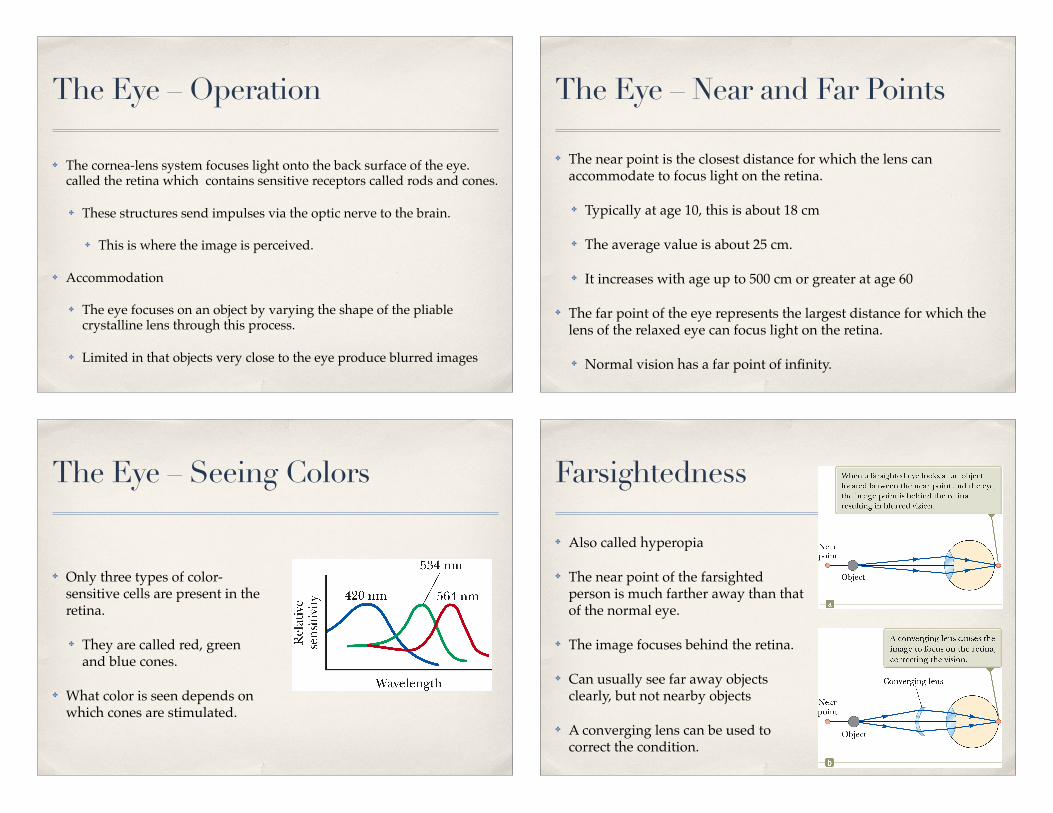
✤ Only three types of color-sensitive cells are present in the retina.
✤ They are called red, green and blue cones.
✤ What color is seen depends on which cones are stimulated.
The Eye – Seeing Colors
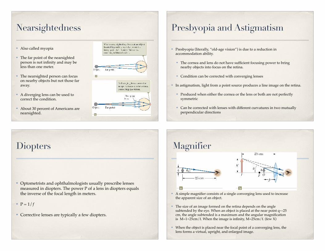
✤ Also called hyperopia
✤ The near point of the farsighted person is much farther away than that of the normal eye.
✤ The image focuses behind the retina.
✤ Can usually see far away objects clearly, but not nearby objects
✤ A converging lens can be used to correct the condition.
Farsightedness
✤ Also called myopia
✤ The far point of the nearsighted person is not infinity and may be less than one meter.
✤ The nearsighted person can focus on nearby objects but not those far away.
✤ A diverging lens can be used to correct the condition.
✤ About 30 percent of Americans are nearsighted.
Nearsightedness
✤ Presbyopia (literally, “old-age vision”) is due to a reduction in accommodation ability.
✤ The cornea and lens do not have sufficient focusing power to bring nearby objects into focus on the retina.
✤ Condition can be corrected with converging lenses
✤ In astigmatism, light from a point source produces a line image on the retina.
✤ Produced when either the cornea or the lens or both are not perfectly symmetric
✤ Can be corrected with lenses with different curvatures in two mutually perpendicular directions
Presbyopia and Astigmatism
✤ Optometrists and ophthalmologists usually prescribe lenses measured in diopters. The power P of a lens in diopters equals the inverse of the focal length in meters.
✤ P = 1/ƒ
✤ Corrective lenses are typically a few diopters.
Diopters
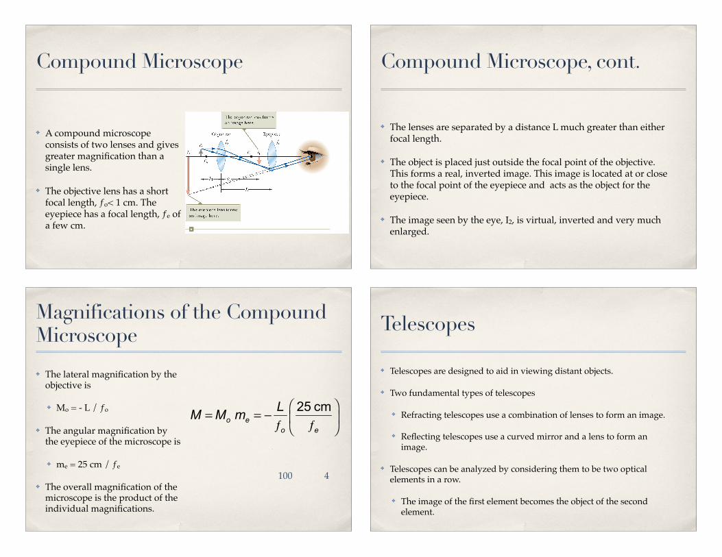
✤ A simple magnifier consists of a single converging lens used to increase the apparent size of an object.
✤ The size of an image formed on the retina depends on the angle subtended by the eye. When an object is placed at the near point q~-25 cm, the angle subtended is a maximum and the angular magnification is M=1+25cm/f. When the image is infinity, M=25cm/f. (few X)
✤ When the object is placed near the focal point of a converging lens, the lens forms a virtual, upright, and enlarged image.
Magnifier
✤ A compound microscope consists of two lenses and gives greater magnification than a single lens.
✤ The objective lens has a short focal length, ƒo< 1 cm. The eyepiece has a focal length, ƒe of a few cm.
Compound Microscope
✤ The lenses are separated by a distance L much greater than either focal length.
✤ The object is placed just outside the focal point of the objective. This forms a real, inverted image. This image is located at or close to the focal point of the eyepiece and acts as the object for the eyepiece.
✤ The image seen by the eye, I2, is virtual, inverted and very much enlarged.
Compound Microscope, cont.
✤ The lateral magnification by the objective is
✤ Mo = - L / ƒo
✤ The angular magnification by the eyepiece of the microscope is
✤ me = 25 cm / ƒe
✤ The overall magnification of the microscope is the product of the individual magnifications.
Magnifications of the Compound Microscope
4100
✤ Telescopes are designed to aid in viewing distant objects.
✤ Two fundamental types of telescopes
✤ Refracting telescopes use a combination of lenses to form an image.
✤ Reflecting telescopes use a curved mirror and a lens to form an image.
✤ Telescopes can be analyzed by considering them to be two optical elements in a row.
✤ The image of the first element becomes the object of the second element.
Telescopes
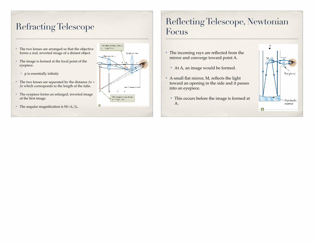
✤ The two lenses are arranged so that the objective forms a real, inverted image of a distant object.
✤ The image is formed at the focal point of the eyepiece.
✤ p is essentially infinity
✤ The two lenses are separated by the distance ƒo + ƒe which corresponds to the length of the tube.
✤ The eyepiece forms an enlarged, inverted image of the first image.
✤ The angular magnification is M=-fo/fe.
Refracting Telescope
✤ The incoming rays are reflected from the mirror and converge toward point A.
✤ At A, an image would be formed.
✤ A small flat mirror, M, reflects the light toward an opening in the side and it passes into an eyepiece.
✤ This occurs before the image is formed at A.
Reflecting Telescope, Newtonian Focus
Recommended