Thermal Compensation:Thermal Compensation:The GEO and LIGO experience and The GEO and LIGO experience and
requirements for advanced detectorsrequirements for advanced detectors
Gregory HarryGregory Harry LIGO/MITLIGO/MIT
On behalf of the LIGO Science On behalf of the LIGO Science CollaborationCollaboration
22 September 200522 September 2005ESF PESC Exploratory ESF PESC Exploratory
Workshop – Perugia ItalyWorkshop – Perugia ItalyLIGO-G050476-00-ILIGO-G050476-00-I

Ryan Lawrence’s ThesisRyan Lawrence’s Thesis
• Two heating techniques
• Ring heater• Scanning CO2 laser
• Ring heater for radially symmetric absorption• Scanning laser for inhomogeneous absorption
• Point absorbers (dust)• Complicated absorption patterns (sapphire)
• Two substrate materials
• Silica• Sapphire
• Excellent results from both techniques on both materials
2

Ryan Lawrence’s Thesis:Ryan Lawrence’s Thesis:Ring HeaterRing Heater
Ring Heater on Silica Optic
Ring heater system • Heat from incandescent source• Shield keeps heat at edge of optic to avoid radial gradients• Excellent correction of radially symmetric thermal lens• Less efficient use of heat than laser
3
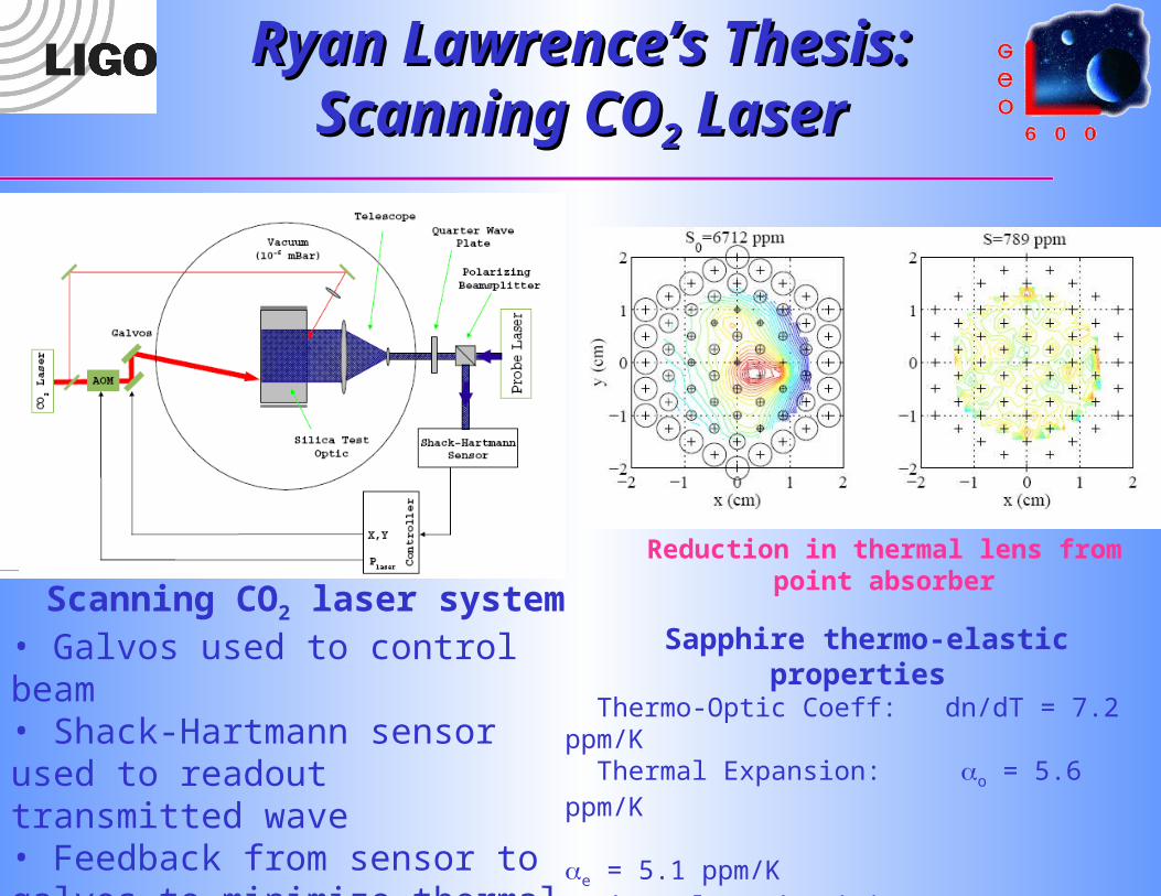
Sapphire thermo-elastic properties
Thermo-Optic Coeff: dn/dT = 7.2 ppm/K Thermal Expansion: o = 5.6 ppm/K e = 5.1 ppm/K Thermal Conductivity: o = 39 W/m/K e = 36 W/m/K Emissivity: = 0.89
Ryan Lawrence’s Thesis: Ryan Lawrence’s Thesis: Scanning COScanning CO22 Laser Laser
Scanning CO2 laser system• Galvos used to control beam• Shack-Hartmann sensor used to readout transmitted wave• Feedback from sensor to galvos to minimize thermal lens
Reduction in thermal lens from point absorber
4
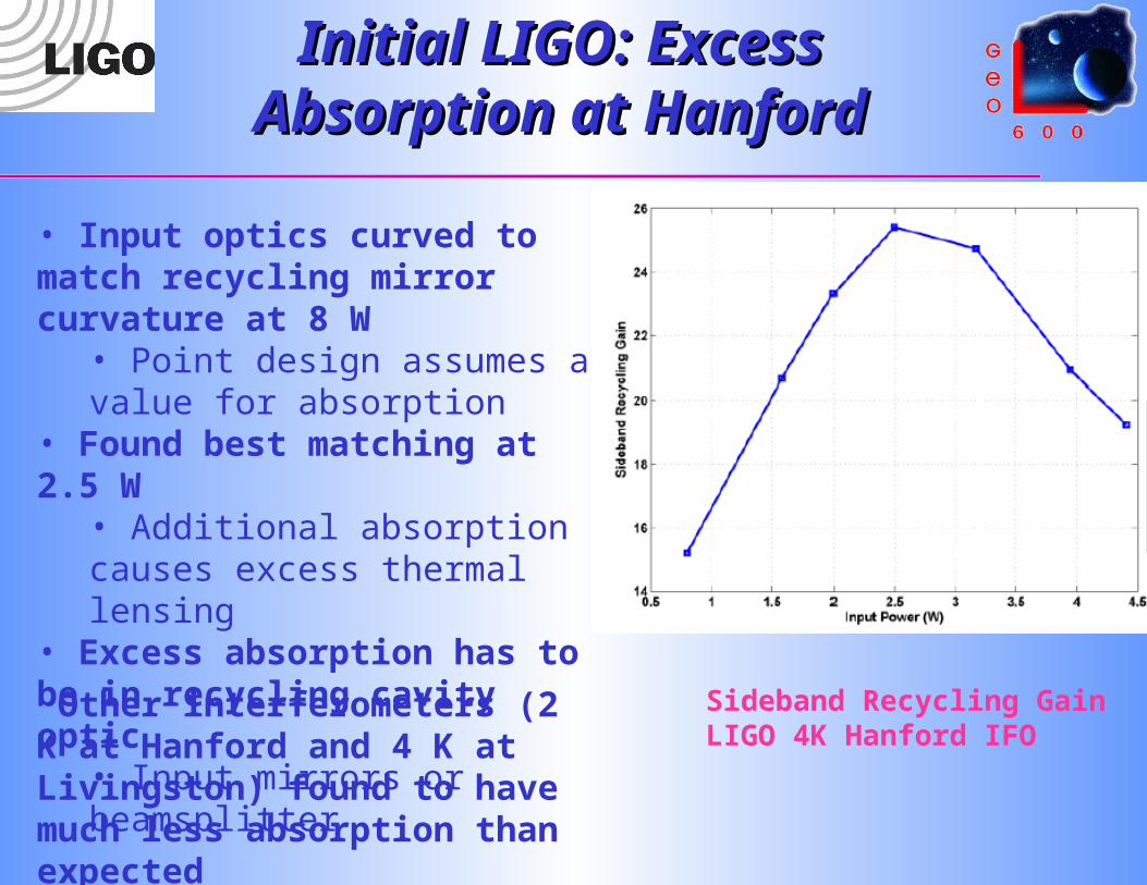
Initial LIGO: Excess Initial LIGO: Excess Absorption at HanfordAbsorption at Hanford
Sideband Recycling GainLIGO 4K Hanford IFO
• Input optics curved to match recycling mirror curvature at 8 W
• Point design assumes a value for absorption
• Found best matching at 2.5 W
• Additional absorption causes excess thermal lensing
• Excess absorption has to be in recycling cavity optic
• Input mirrors or beamsplitter
Other interferometers (2 K at Hanford and 4 K at Livingston) found to have much less absorption than expected 5
6
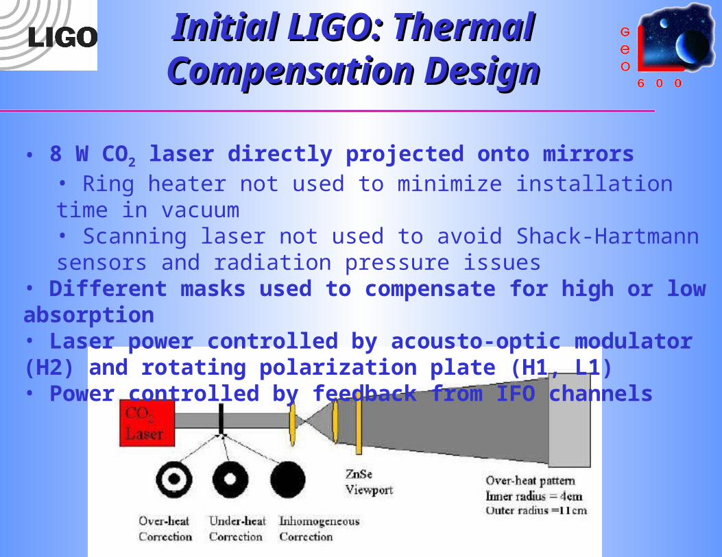
• 8 W CO2 laser directly projected onto mirrors• Ring heater not used to minimize installation time in vacuum• Scanning laser not used to avoid Shack-Hartmann sensors and radiation pressure issues
• Different masks used to compensate for high or low absorption• Laser power controlled by acousto-optic modulator (H2) and rotating polarization plate (H1, L1)• Power controlled by feedback from IFO channels
Initial LIGO: Thermal Initial LIGO: Thermal Compensation DesignCompensation Design

7
Initial LIGO: Effects of Initial LIGO: Effects of Thermal CompensationThermal Compensation
• Resolution 6 mm, limited by ZnSe window aperture• Underheat mask – Gaussian profile same as main beam• Overheat mask – Annulus with radii optimized • Poor illumination at 3 - 4.6 W from high RF power in AOM
• Switch to polarizer as control mechanism
8
Initial LIGO: Noise from Initial LIGO: Noise from Thermal CompensationThermal Compensation
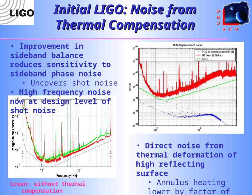
Green: without thermal compensation
Red: with thermal compensation
• Direct noise from thermal deformation of high reflecting surface
• Annulus heating lower by factor of 10
• Improvement in sideband balance reduces sensitivity to sideband phase noise
• Uncovers shot noise• High frequency noise now at design level of shot noise

9
Initial LIGO: Excess Initial LIGO: Excess Absorption at HanfordAbsorption at Hanford
• Three techniques used to determine source of excess absorption
• Change in g factor • Thermal compensation power• Change in spot size
• Fairly consistent result (assuming absorption in HR coating)
• ITMx 26 ppm• IMTy 14 ppm• Design 1 ppm
• Resulting changes• ITMx replaced• ITMy drag wiped in situSpot size measurements: Data and
technique
Initial LIGO: Absorption Initial LIGO: Absorption improvement at Hanfordimprovement at Hanford
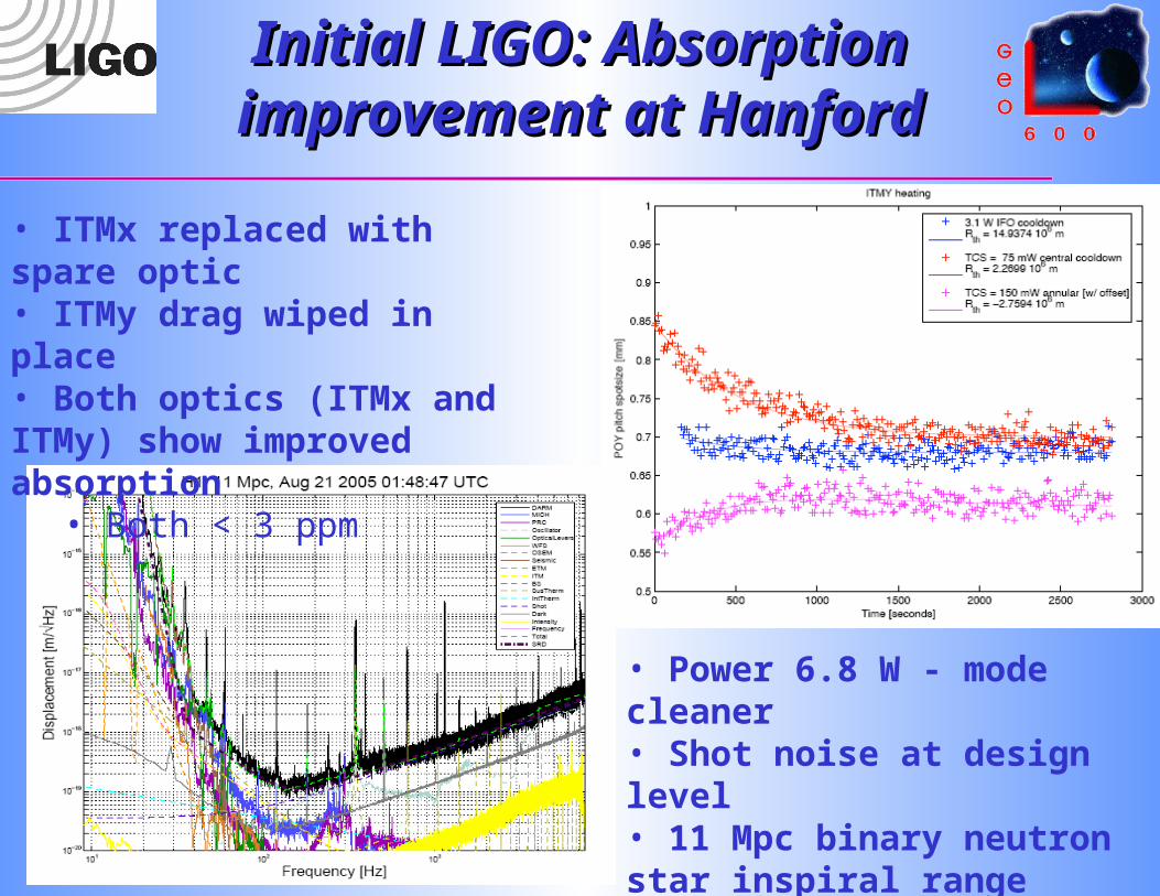
• ITMx replaced with spare optic• ITMy drag wiped in place • Both optics (ITMx and ITMy) show improved absorption
• Both < 3 ppm
• Power 6.8 W - mode cleaner• Shot noise at design level• 11 Mpc binary neutron star inspiral range

11
Initial LIGO: Bench Initial LIGO: Bench Tests of H1:ITMxTests of H1:ITMx
Dust source of absorption?• Soot from brush fire in 2000?• Attracted by charged surface?• Insufficient cleaning and handling procedures?
• H1:ITMx shipped to Caltech immediately after removal• Absorption measured using photothermal common-path interferometry• Background < 1 ppm• Significant outliers with absorption > 40 ppm
12
GEO: Power and locking GEO: Power and locking problemproblem
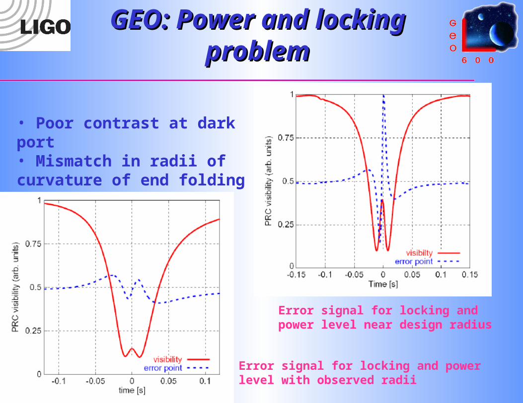
Error signal for locking and power level near design radius
Error signal for locking and power level with observed radii
• Poor contrast at dark port • Mismatch in radii of curvature of end folding mirrors

13
GEO: Control of optic GEO: Control of optic with ring heaterwith ring heater
• Ring heater installed behind east end folding mirror• Thermal expansion changes radius of curvature• Radius
• East 687 m -> 666 m• North 660 m
• Increase in heater power changes contrast defect• Slight astigmatism causes horizontal and vertical curvature match to be at different powers• 71 W best compromise

14
Advanced: Upgrades and Advanced: Upgrades and challengeschallenges
• Initial LIGO compensation effective at 100 mW absorbed
• Advanced LIGO expected to have 350 mW absorbed• Cleanliness and handling will be crucial
• Need to keep absorption down
• Potential improvements for advanced detectors• Graded absorption masks• Scanning laser system• Compensation plate in recycling cavity• Graded absorbing AR coating• DC readout, reducing requirements on RF sidebands
• Challenges• Greater sensitivity• New materials – sapphire ~ 20 ppm/cm absorption• Compensation of arm cavities• Inhomogeneous absorption• Noise from CO2 laser
PRM
SRM
ITM
ITM
Compensation Plates

Advanced: Losses in Advanced: Losses in signal recycling cavitysignal recycling cavity
• Scatter in signal recycling cavity up convert gravity-wave sidebands
• Sets the most severe limit on thermal aberrations• ~ 0.1 % loss from TEM00
mode • ~ 5% loss in sensitivity
• Low frequency sensitivity set more by thermal noise
• Less effect from thermal aberrations
15

Advanced: Lasers and Advanced: Lasers and ring heatersring heaters
• Ring heaters simplest compensation system• Adds a lot of unnecessary heat • Could cause thermal expansion of other parts
• Scanning laser system causes noise• Jumps in location cause step function changes in thermal
expansion• Harmonics of jump frequency could be in-band• Could require feedback with Hartmann sensors or similar
• Staring laser system works on initial LIGO• Could require unique masks for each optic• Unique masks could be inappropriate as system is heating
up• CO2 laser noise still a problem
16

ContactsContacts
• Initial LIGO Thermal Compensation• Dave Ottaway – ottaway@ ligo.mit.edu • Phil Willems – willems@ ligo.caltech.edu
• Hanford Optic• Dave Ottaway – ottaway@ ligo.mit.edu• Garilynn Billingsley – billingsley_g@
ligo.caltech.edu• Bill Kells – kells@ ligo.caltech.edu• Liyuan Zhang – zhang_l@ ligo.caltech.edu
• GEO Thermal Compensation• Stefan Hild –stefan.hild@ aei.mpg.de• Harald Lück – harald.lueck@ aei.mpg.de
• Advanced LIGO Plans• Dave Ottaway – ottwaway@ ligo.mit.edu• Phil Willems – willems@ ligo.caltech.edu
Recommended