SK-189
.
THE VIDEO TAPE RECORDING OFULTRASONIC TEST INFORMATION
This document has been approved
for public release and sale; its
distribution is unlimited.
r-
!.,,.,.
SHIP STRUCTURE COMMITTEE
—.,-- —-—.——-. -. ......-: — ... _ —“— — .—. _ .. .—
SHIP STRUCTURE COMIWTTEE
/AEMBER AGENCIES:
UNITED STATES COAST GUARD
NAVAL SHIP SYSTEMS COMMAND
MILITARY SEA TRANSPORTATION sERVICE
MARITIME ADMINISTRATION
AMERICAN BUREAU OF SHIPPING
October 1968
Dear Sir:
The increasing use of ultrasonic incontrol of ship welding has prompted the Shipto seek methods of recording the results of tsequent review and analysis. No such methodheretofore. The enclosed report l% Video Tatmaonie Test Information by R. A. Youshaw,Criscuolo describes the development of a firsfor recording the ultrasonic test informationSuggestions are made for further developmentmore useful in shipyards.
This report is being distributedgroups associated with or interested in th
Structure Committee. Comments concerning thi ted.
Sincerely y
IM,ld-%D. B. HendeRear AdmiraChairman, S
I
ADDRESS CORRESPONDENCE TO:
SECRETARY
SHIP STRUCTURE COMMITTEE
U.S. COAST OUARD HEADQUARTERS
WASHINGTON, D.C. 2069!
)ection for qualityjtructure Committeeis testing for sub-~s been availablez Reeo~dhg of Ul-
H. Dyer and E. L.generation method
on magnetic tape.) make the system
:0 individuals andwork of the Ship
; report are solic-
ion, U. S. Coast Guardip Structure
Committee
-. .— .———. ,... —— !—
SSC-189
Final Report
on
Project 176
“Quality Assurance”
to the
Ship Structure Committee
THE VIDEO TAPE RECORDING OF ULTRASONICTEST INFORMATION
by
Robert A. Youshaw, Charles H. Dyerand Edward L. Criscuolo
United States Naval Ordnance Laboratory
under
Department of the NavyNaval Ship Engineering CenterProject Order No, PO-6-0039
U. S. Coa~t Guard HeadquartersWashington, D. C.
This document has been approved for public release and sale;its distribution is unlimited.
October 1968
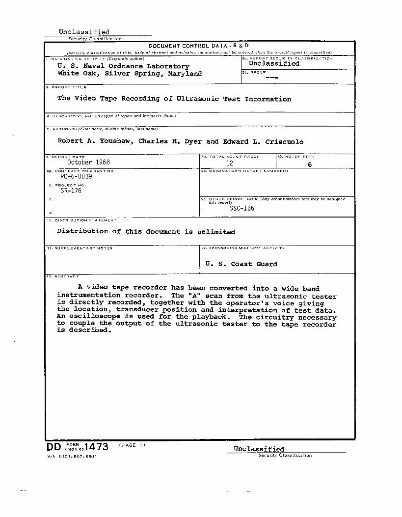
ABSTRACT
A video tape recorder has been converted into a
wide band instrumentation recorder. The “A” scan from
the ultrasonic tester is directly recorded together
with the operator’s voice giving the location, trans-
ducer position and interpretation of test data. An oscil-
loscope is used for the playback. The circuitry necessary
to couple the output of the ultrasonic tester to the tape
recorder is described.
SHIPSTRUCTURE COMMITTEE
The SHIP STRICTURE COMMITTEE is constituted to prosecute a research program to improve the
hull structures of ships by an extensfon of knowledge pertaining to design, materfals and methods
of fabrication.
Captain R.Head, ShipNaval Ship
Captain T.
RADM D. B. Henderson, USCG - ChairmanChief, Office of EngineeringU. S, Coast Guard Headquarters
T. Miller, USN Mr. E. Scott’DillonEngineering Department Chief, Division of Ship DesignEngineering Center Office of Ship Construction
Mar~time Administration
J. Banvard, USN Mr. D. B. Bannerman, Jr.Maintenance and Repair Officer Vice President - TechnicalMilitary Sea Transportation Service American Bureau of Shipping
SHIP STRUCTURE SUBCOMMITTEE
The SHIP STRUCTURJZSUBCOMMITTEE acts for the Ship Structure Committee on technical
matters by providing technical coordination for the determination of goals and objectives of
the program, and by evaluating and interpreting the results in terms of ship structural design,
construction and operation.
NAVAL SHIPENGINEERING CENTER OFFICE OF NAVAL RESEARCH
Mr. J. J. Nachtsheim - Chairman Mr. J. M. Crowley - MemberMr. John Vasta - Contract Administrator Dr. Wm. G. Rauch - AlternateMr. George Sorkin - MemberMr. Parrison S. Sayre - Alternate MILITARY SEA TRANSPORTATION SERVICEMr. Ivo Fioriti - Alternate LCDR R. T. Walker, USN - Member
MARITIME ADMINISTRATIONMr. R. R. Askren - Member
Mr. Frank Dashnaw - Member U. S. COAST G~!ARDMr. Anatole Maillar - MemberMr. R. Falls - AlternateMr. W. G. Frederick - Alternate
AMERICAN BUREAU OF SHIPPING
CDR C. R. Thompson, USCG - MemberCDR J. L. Howard, IJSCG- memberLCDR Leroy C. Melberg, USCG - AlternateLCDR R. L. Brown, USCG - Alternate
Mr. G. F. Casey - MemberMr. F. J. Crum - Member
NAVAL SHIp RESEARCH ~ DEVELOPMENT CENTER
Mr. A. B. Stavovy - Alternate
LIAISON REPRESENTATIVES
NATIONilLACADEMY OFNATIONAL RESEARCH
sclm’JcEs-COUNCIL
BRISTISH NAVY STAFF
Mr. A. R. Lytle - Technical Dfrector, MaritimeMr. H. E. HoSben
Transportation Research BoardStaff Constructor OfficerDouglas Faulkner, RCNC
Mr. R. W. Rumke - Executive Secretary, S17C WELDING RESEARCH COUliCI1.
AMERICAN IRON AND STEEL INSTITUTE Mr. K. H. Koopman, Director
Mr. J. R. LeCronMr. Charles Larson, Asst. Director
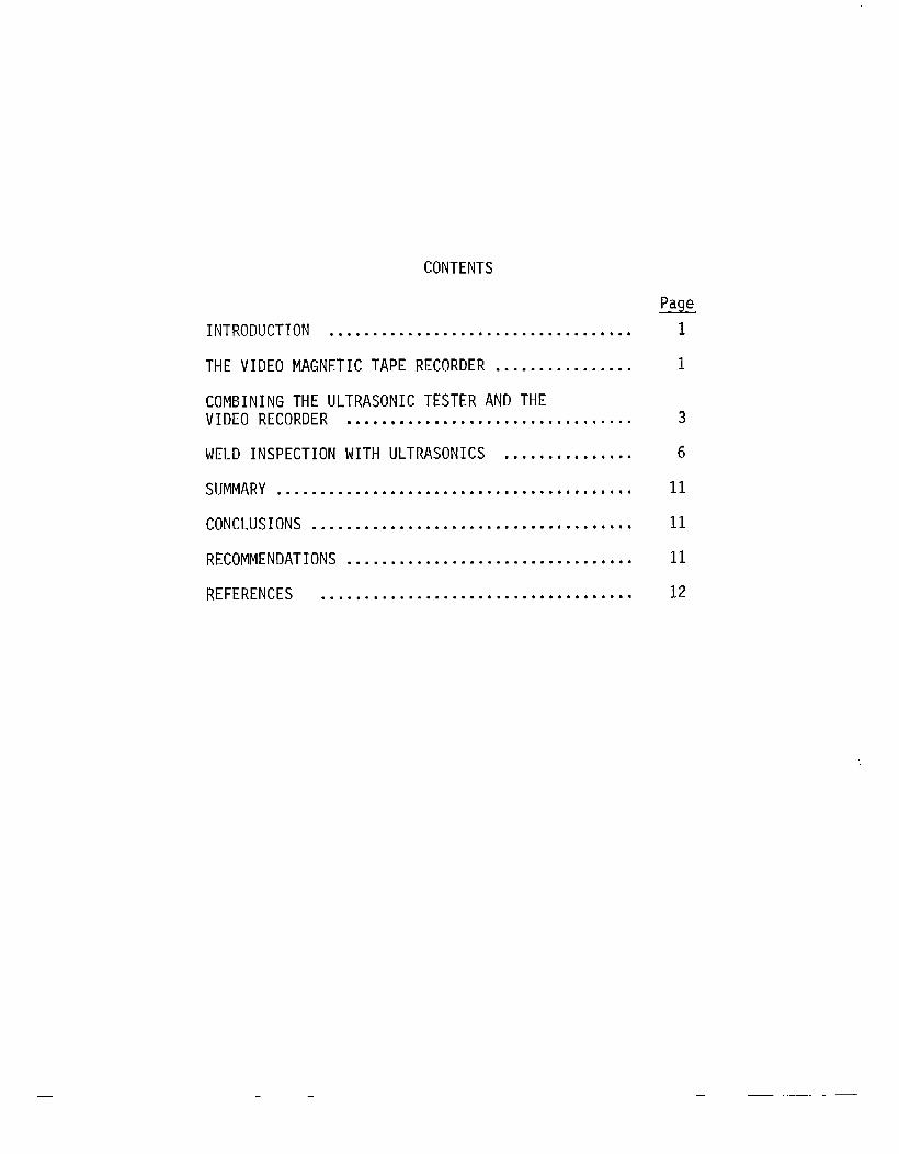
CONTENTS
Page
INTRODUCTION ● ***...... .......*.............**.* 1
THE VIDEO MAGNETIC TAPE RECORDER ................ 1
COMBINING THE ULTRASONIC TESTER AND THEVIDEO RECORDER ...*.... ........● .**.*** ● ****.... 3
WELD INSPECTION WITH ULTRASONICS ....*.*. ● *****. 6
SUMMARY ● .........● ● ● ● ● ● ..● .............**** ● **● * 11
CONCLUSIONS ......*.* ● ****.*.. ..........*...**** ● 11
RECOMMENDATIONS .....*** ● ***.................***. 11
REFERENCES ...● .● ● ● ● ..........● ....● ● ● ● .*● ..... 12
— —
The lack of a primary record of inspection hasdecidedly retarded the acceptance of ultrasonics as an inde-pendent inspection tool, and much effort has been directedtoward devising a means of recording the ultrasonic testinformation. Limited applications have been found for C scanJ(l), strip chart (2), photography (3), and amplitude mapping(4), but, in general, the record obtained using these methodsis not complete and a need does exist for a practical recordingsystem which will provide a complete record of the ultrasonictest.
In ultrasonic testing of materials, information isobtained from the presence (or absence) of a signal, theamplitude shape and screen position of the signal, the loca-tion and orientation of the transducer, and also from thechange in the ultrasonic indications brought about by motionof the transducer. In addition, the extent of meaning whichcan be attached to these factors is directly related to anddependent upon the calibration of the instrument.
Recording the ultrasonic signal on magnetic tape andsupplementing this information by also recording the operator’svoice description of the test conditions would provide acomplete record. There are, however, certain technical con-siderations which place restrictions upon the types of taperecorders which can be used for this purpose. If, for example,the ultrasonic test is required to differentiate betweendistances as small as l/10-inch and the material is steelwith an approximate velocity of sound (“transversewaves)of125,000 inches per second, (5) then the recorder must have afrequency response of 1.25 MHs. Also, from a simple oscillo-scope measurement, the width of an average ultrasonic pulsehas been determined to be 2 microseconds. A pulse of thiswidth requires a frequency response of at least l/2-MHz.The frequency response of video recorders meet these technicalrequirements and the recent marketing of comparativelyinemensive portable mmdels makes this approach practical.
The purpose of this work is to develop a system andstudy the application of commercially available video magnetictape recording equipment to the problem of recording ultrasonictest information. Although the inspection examples consideredin this work are confined to manually inspected steel welds,the method is applicable to all materials and types of ultra-sonic inspection.
THE VIDEO MAGNETIC TAPE RECORDER
A survey was made of the available low cost videorecorders, and the Ampex VR7000 was selected for use in thisstudy. This instrument has a frequency response of 3.5 MHz
.—
-2-
and is commercially available for approximately $3,500. ltweighs about 100 pounds and has dimensions of 29’’x18’’xli’i.
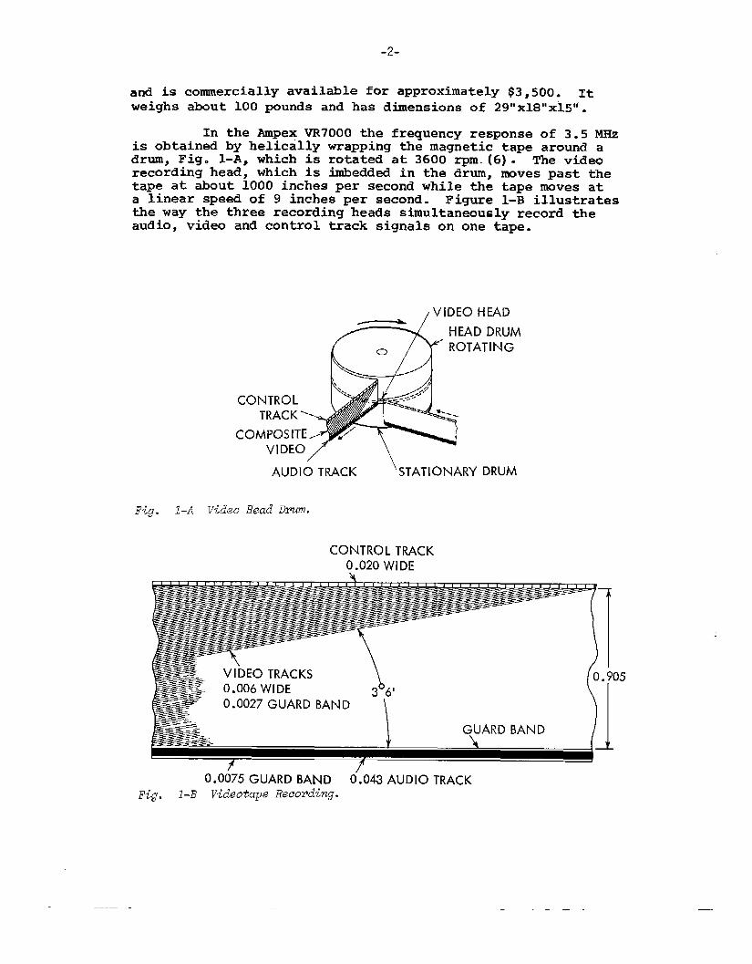
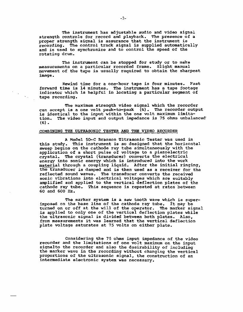
In the Ampex VR7000 the frequency response of 3.5 MHsis obtained by helically wrapping the magnetic tape around adrum, Fig. l-A, which is rotated at 3600 rpm. (6). The videorecording head , which is imbedd~ in the drum, nmves past thetape at about 1000 inches per second while the tape moves ata linear speed of 9 inches per second. Figure 1-B illustratesthe way the three recording heads simultaneously record theaudio, video and control track signals on one tape.
CONT
COM
Fig. I-A vid~o Head Dm.
CONTROL TRACK0.020 WIDE
5
0.0075 Gw4RD BAND 0.043 AUD1O TRACK
F{g. 1-B ~-id~otapaReeo~ding.
-. .—
-3-
The instrument has adjustable audio and video signalstrength controls for record and playback. The presence of aproper strength signal is assurance that the instrument isrecording. The control track signal is supplied automaticallyand is used to synchronize and to control the speed of therotating drum.
The instrument can be stoPPed for study or to makemeasurements onmovement of theimage.
Rewindforward time isindicator whichtape recording.
a particular recorded frame. Slight manualtape is usually required to obtain the sharpest
time for a one-hour tape is four minutes. Fast14 minutes. The instrument has a tape footageis helpful in locating a particular segment of
The maximum strength video signal which the recordercan accept is a one volt peak-to-peak (6). The recorder outputis identical to the input within the one volt maximum limita-tion. The video input and output impedance is 75 ohms unbalanced(6).
cOMBINING THE ULTRASONIC TESTER AND THE VIDEO RECORDER
A Model 50-C Branson Ultrasonic Tester was used inthis study. This instrument is so designed that the horizontalsweep begins on the cathode ray tube simultaneously with theapplication of a short pulse of voltage to a piezoelectriccrystal. The crystal (transducer) converts the electricalenergy into sonic energy which is introduced into the workmaterial through a coupling liquid. After the initial ringing,the transducer is dampd and-is then used as a receiver for thereflected sound waves. The transducer converts the receivedsonic vibrations into electrical voltages which are suitablyamplified and applied to the vertical deflection plates of thecathode ray tube. This sequence is repeated at rates between60 and 600 Hz.
The marker system is a saw tooth wave which is super-im~sed on the base line of the cathode ray tube. It may beturned on or off at the will of the operator. The marker signalis applied to only one of the vertical deflection plates whilethe ultrasonic signal is divided between both plates. Also,from measurements it was learned that the vertical deflectionplate voltage saturates at 75 volts on either plate.
Considering the 75 ohms input impedance of the videorecorder and the limitations of one volt maximum on the inputsignalto the recorder and also the desirability of includingthe marker wave in the recording without changing the verticalproportions of the ultrasonic signal, the const~ction of anintermediate electronic system was necessary.
-4-
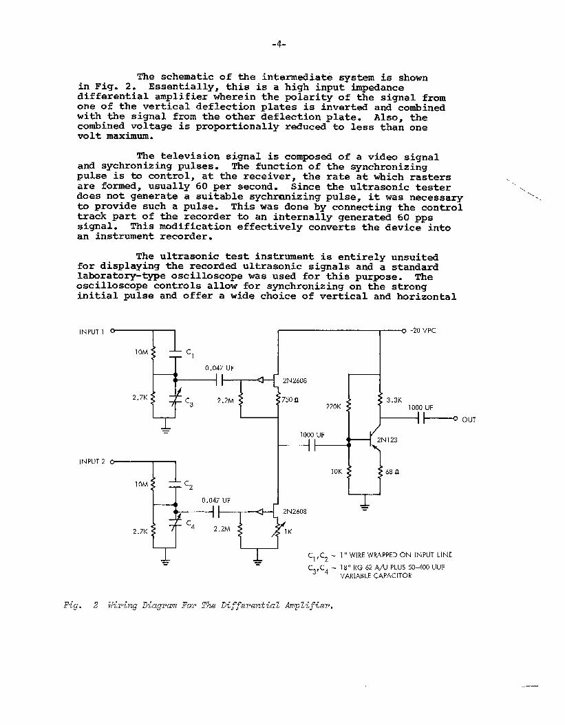
The schematic of the intermediate system is shownin Fig. 2. Essentially, this is a high input impedancedifferential amplifier wherein the polarity of the signal fromone of the vertical deflection plates is invert~ and combinedwith the signal from the other deflection plate. Also, thecombined voltage is proportionally reduced to less than onevolt maximum.
The television signal is composed of a video signaland synchronizing pulses. The function of the synchronizingpulse is to control, at the receiver, the rate at which rastersare formed, usually 60 per second. Since the ultrasonic testerdoes not generate a suitable sychrcmizing pulse, it was necessaryto provide such a pulse. This was done by connecting the controltrack part of the recorder to an internally generated 60 ppssignal. This modification effectively converts the device intoan instrument recorder.
The ultrasonic test instrument is entirely unsuitdfor displaying the recorded ultrasonic signals and a standardlaboratory-type oscilloscope was used for this pur~se. Theoscilloscope controls allow for synchronizing on the stronginitial pulse and offer a wide choice of vertical and horizontal
INPUT 1
INPUT 2
10M‘1
0.047 UF
II A 2N2608
2.7KC3
2.2M 7500220K 9,
0
= 1000 UF
II
IOK
10M
----4 I0.047 UF
II =
2.7KC4 2.2M
C1’C2 -l’~WIREWRAPPEDOk.l INPUT LINE
m =C3, C4 - ls’~ RG 62 A/U PLUS 50-400 UUF
VARIABLE CAPACITOR
OUT
Fig. 2 WiYing Diag2wn FOP The Diffwwztia2 Amplifier.
_.—
-5-
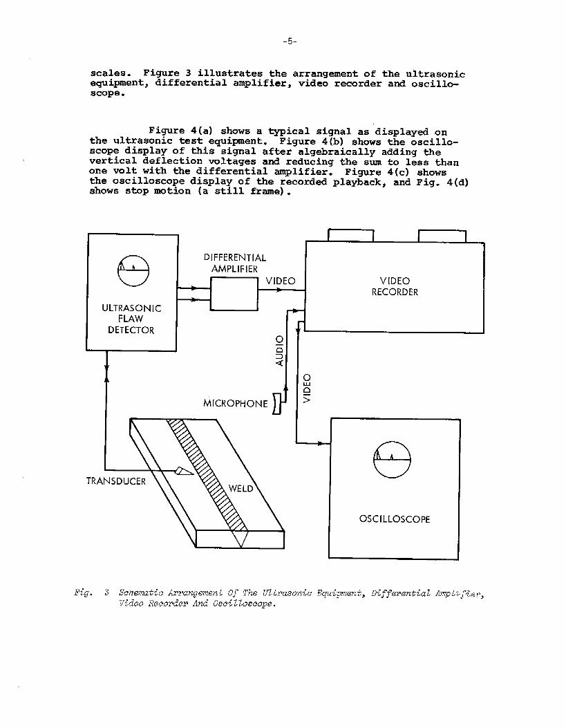
scales. Figure 3 illustrates the arrangement of the ultrasonicequipment, differential amplifier , video recorder and oscillo-scope.
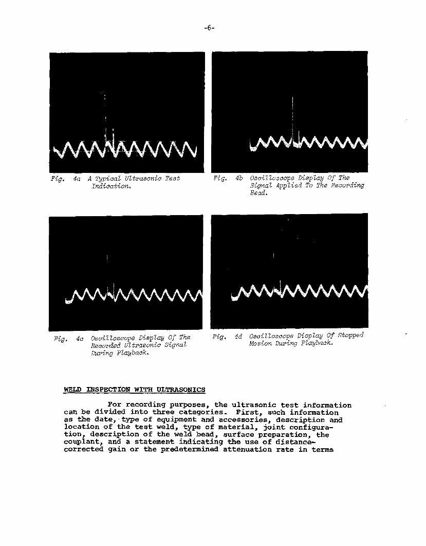
Figure 4(a) shows a typical signal as displayd onthe ultrasonic test equipment. Figure 4(b) shows the oscillo-scope display of this signal after algebraically adding thevertical deflection voltages and reducing the sum to less thanone volt with the differential amplifier. Figure 4(c) showsthe oscilloscope display of the recorded playback, and Fig. 4(d)shows stop motion (a still frame).
(9ULTRASONIC
FLAWDETECTOR
DIFFERENTIALAMPLIFIER
e
MICROPH
I i I [
VIDEORECORDER
>
eOSCILLOSCOPE
Fig● 3 SchematicArrangement Of Tk llzt~asonieEquipment,DifferentialAmpL~~%eP,Video Reeorde~ And O.se{ZZoseope,
-6-
??ig. 4b Osei220seopeDisplay Of TheSignal Applied To The Reeo~dingHead.
Fig. 4d OscilloscopeDisplay Of s-topp~dMotion ~ring playback.
WELD INSPJ3CT~ONWITH ULTRASONICS
For recording purposes, the ultrasonic test informationcan be divided into three categories. First, such informationas the date, -type of equipment and accessories, description andlocation of the test weld, type of material, joint confi~ra-tion, description of the weld bead, surface preparation, thecouplant, and a statement indicating the use of distance-corrected gain or the predetermined attenuation rate in terms
-1-
of decibels per inch. Second, there is the demonstration ofproper instrument calibration, and third, the significantindications of the ultrasonic test.
The separate audio track of this instrument affordsan easy solution for recording the first category of information.However, there is a need for brevity of speech and a sequentialkey work code can be used to advantage. For example:
a.b.c.d.e.f.
::i..
21.
Operator’s identityDateType of instrumentTransducer type, size, frequency and angleIdentification of test objectLocation of the weldType of materialThickness of base plateType of joint and configurationCondition of the weld beadCouplantAttenuation factor.
A typical statemen~ of general test conditions mightbe as follows: John Doe, 5 Sep 1967, Branson 50-C, BariumTitanate, l/2’’xl”,2.25 MHz, 45”, Merchant Ship, Virginia Beach,22’4-1/2” below top centerline, 5’7” forward of Rib #3, HY-80steel, 3/4”, Butt-double “V”, ground flush, glycerin, 2 decfielsper inch. This information can be recorded in 15 to 20 seconds.
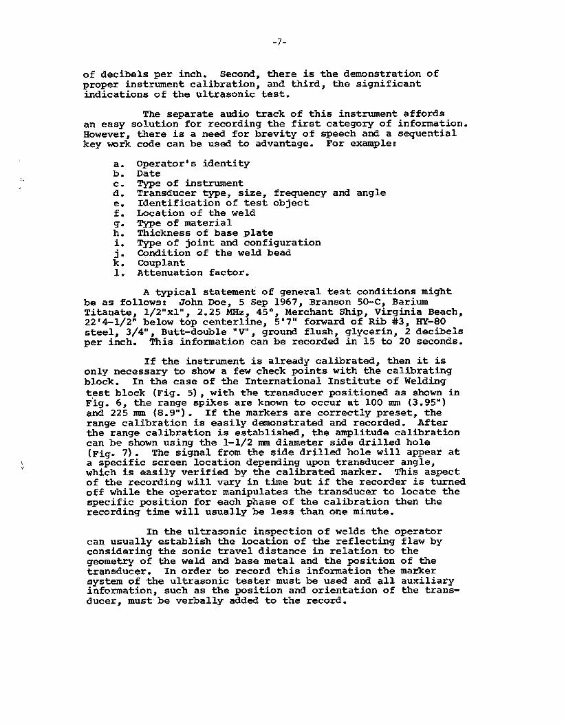
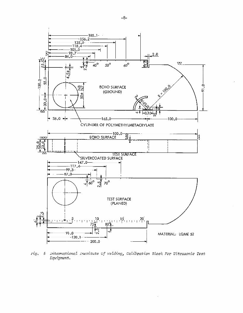
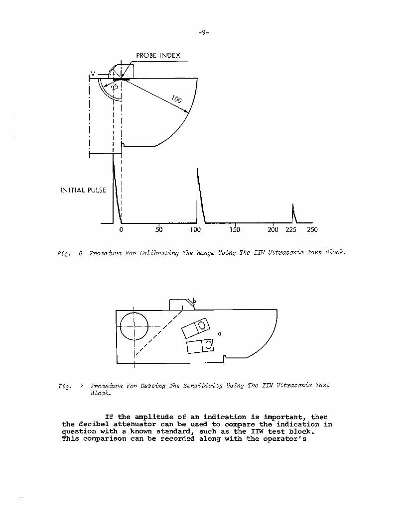
If the instrument is already calibrated, then it isonly necessary to show a few check Pints with the calibratingblock . In the case of the International Institute of Weldingtest block (Fig. 5), with the transducer positioned as shown inFig. 6, the range spfies are known to occur at 100 nun (3.95”)and 225 nun (8.9”). If the markers are correctly preset, therange calibration is easily demonstrated and recorded. Afterthe range calibration is established, the amplitude calibrationcan be shown using the 1-1/2 mm diameter side drilled hole(Fig. 7). The signal from the side drilled hole will appear ata specific screen location depending upon transducer angle$which is easily verified by the calfirated marker. This aspectof the recording will vary in time but if the recorder is turnedoff while the operator manipulates the transducer to locate thespecific position for each phase of the calibration then therecording time will usually be less than one minute.
In the ultrasonic inspection of welds the operatorcan usually establish the location of the reflecting flaw byconsidering the sonic travel distance in relation to thegeometry of the weld and base metal and the position of -etransducer. In order to record this information the markersystem of the ultrasonic tester must be used and all auxiliaryinformation, such as the position and orientation of the trans-ducer, mustbe verbally added to the record.
-8-
!
If0m“
001 .
g“, 8-1
-iLoo“m
,7“4’ 40° 50° 60°— w ‘.,-
~~ w
ECHO SURFACE
(GROUND)
\
-35.0- =\kyLINDER OF pOLyhtETHYLMETKRy MTE
100.0 ~w I ECHO SURFACE ~ + a------
~~~-II 1Ii
‘=J I I //-- —-- —m 1
i
TEST 5URFACt~SILVERCOATED SURFACE
~Ly~~
e’” ‘q 60° ? 70°
m
+
TEST SLIRFACE(PLANED)
m
+-4iml
i5—1ll, ,, ,,, , l’1’l’1~’p’111~11
15 ,,, ,, ,2$c1 1’[’
T’1 75$ 80+
Lmo --ItUIm“ w
Fig● 5 IntamwtionaL Institute Of Welding, CalibrationEquipment.
MATERIAL: LQME 52
Flock FOP UltrasonicTest
-9-
INITIAL
PROBE INDEXI 1
II
1 II
PULSE I
\1 I
o1
50 100 150 200 225 250
Fig. 6 -oeeduzw .FOrCaZib~atingThe Range Using The XXW U2tirasonieT@stiBLoek.
Fig. 7 Procedure FOP Setting The Sensitivity Using The IIW UztrazonieTestBlock.
If the amplitude of an indication is important, thenthe decibel attenuator can be USA to compare the indication inquestion with a known standard, such as the IIW test block.This comparison can be recorded along with the operator’s
-1o-
statement of the number of decibels added to or subtractedfrom the system.
The end points of a linear defect, such as incompletepenetration, are located by finding the positions where thesteady value of the amplitude drops to one-half (4). At thesepoints half of the sonic beam is intercepted and reflected bythe flaw and the end of the linear defect is located along thecenterline of the transducer. A meaningful record of a lineardefect should include the demonstration of both the steadyamplitude and the half value with verbal descriptions oftransducer positions and any decibel attenuation changes madeby the operator.
The half-amplitude technique is also applicable tothe determination of “extent of depth” of a defect which isoriented perpendicular to the surface of the base metal. Therecording technique for “extent of depth” would require theoperator’s statement of transducer position at one-half ampli-tude point and the amount of linear motion as the transducer ismoved to cause the signal to increase through the peak and thento reach the other half-amplitude point.
Large single gas holes are recognized by beingdetectable from any direction. This is also true for clustersof porosity: however, the signal obtained from the cluster ismore bulbous. Both of these conditions can be recorded bystating the multi-directional detection of the flaw, showinga typical ultrasonic indication and noting the position andorientation of the transducer.
Certain defects such as lack of fusion are morereadily detect~ from a particular side of the weld with markeddifference in signal strength between the two directions ofinspection. This difference is usually attributed to theorientation of the defect at some angle from the vertical. Therecording for this type of defect should include inspection fromboth sides of the weld.
Entrapped slag is not a good reflector of sonicenergy and the noticeable difference between the size (profile)of the flaw and the signal amplitude is an aid in identifyingthis defect. The length and extent of depth can be establishedas previously descrfied. These two dimensions provide a crudeprofile and the amplitude can be evaluated with the decibelattenuator. men compared with the profile the numericalvalues of the signal strength are seen to differ markedly fromair gap type defects. The recording should include the determi-nations of flaw size and peak amplitude.
Cracks are considered to be serious defects andusually necessitate repair. Both the length of the crack andthe depth are important and should be a part of the record ofinspection.
-11-
Undercut can be detected with ultrasonics as well asby visual inspection. Usually finger damping of the undercutwill establish this flaw as the source of an ultrasonic signal.The effect of the finger damping on the ultrasonic signal canbe shown with a verbal explanation if this condition is ofim~rtance.
Since the test information is recorded on long playingtape, a note should be made of the footage indicator readingfor each separate recording. This will make it easier toretrieve specific recordings.
SUMMARY
The acceptance of ultrasonics as an independentinspection tool has been retarded by the lack of a primaryrecord of inspection. Although many different systems havebeen tried, a comprehensive recording method has not existed.It appeard feasible to couple a magnetic voice recording withportable video recording equipment and thus record all perti-nent information. Such an attempt was made by slightlymodifying commercially available equipment. Although someimprovaents are still desired, a more satisfactory recordingof ultrasonic test information has essentially been realized.
03NCLUSIONS
The ultrasonic test information is at presentrecorded with reasonably good fidelity. Some change isnecessary, however, before this equipment can be consideredsuitable for use at a shipyard.
The video tape recording of ultrasonic test informa-tion is satisfactory for immediate use in training equipmentoperators, inspection and specification writing personnel.
REcOMMENDATIONNS
In its present physical state, this equipment istoo bulky and cumbersome to apply to shipyard problems as ithinders the operator’s freedom of movement. It is recommendedthat a system be devised for transmitting both audio and videosignals to a stationary recorder.
The magnetic tape is not utilized efficiently inrecording ultrasonic signals because the lapsed time betweenpulses exceeds the actual recording period. To achievegreater economy it is recommended that information be recordedon both edges of the tape and the ultrasonic tester and therecorder be synchronized.
In the course of this work, it was observed that therecorder generates a 55 Hz pulse which is sufficient to pre-trigger the oscilloscope on playback. These pulses have been
-12-
traced to certain silicon control rectifiers which are a partof the motor drive circuit but the did not permit determiningwhether this is inherent to the instrument or the result offaulty components. It is therefore reconnnended that suchpre-triggering be eliminated, if possible.
REFERENCES
(1)
(2)
(3)
(4)
(5)
(6)
Pawlowski, Zdzislaw - “standardization of UltrasonicTesting of Welds,” Proceedings of the Third Inter-national Conference on Nondestructive Testing, Tokyoand Osaka, Mar 1960, Pan-Pacific Press, Tokyo 1961pp 663-667Youshaw, R. A. - “A Survey of the Ultrasonic Inspec-tion of Welds,” NOLTR 67-29, 15 Feb 1967Maebashi, Yoichi, and Kestner, Fritz A. - “The m-scopeMethod and its Application,” Proceedings of the ThirdInternational Conference on NDT, pp 583-587NAVSHTPS O9OO-OO6-3O1O - “Ultrasonic InspectionProcedures and Acceptance Standards for HU1l StructureProduction and Repair Welds,” Navy Department,Washington, D. C. 1960~NDESTRUCTIVE TESTING HANDBOOK, vol. 11, 43.8The Ronald Press Company, New York 1959Operating Manual for Ampex Videotape Recorder,Model VR7000
unclassifiedSecuritv Classi[icat:on
DOCUMENT CONTROL DATA- R&DISPCUrItY Ctassificatiofl Of title, body of +bstract <<rid rrnlcxi,lg arznoiation rnu.,1 be cnlcrcd when the OVCrLIII TcPort is Cl<?ss;[jed)
ORIGINATING AC TIVITV (Corporate author) 2a. REF’ORT SECURITY CL A5SIF IC AT ION
U. S. Naval Ordnance Laboratory Unclassified
White Oak, Silver Spring, Maryland 2b. GROUP
---
The Video Tape Recording of Ultrasonic Test Information
DESCRIPTIVE NOTEs(Type ofrcport and inctuslvL’ dates)
AuTHOR(5) (First name, middle initial, last name)
Robert A. Youshaw, Charles H. Dyer and Edward L. Criscuolo
REPORT DATE 7a. TOTAL NO. OF PAGES 7b. NO. OF RFFS
October 1968 12 6a. CO NT R4CT OR GRANT No. 9a. OR IGINATOR*5 REPORT NUMB ER(5I
PO-6-0039b. PROJECT NO,
SR-176 Ic. gb. OTHER REPORT NO(51 (Any other mmibc,s that may b. ezsigned
this report)
SSC-186d.O, DISTRIBUTION STATEMENT
Distribution of this document is unlimited
1. SUPPLEMENTARY NOTES 12. SPONSORING MILITARY ACTIVITY
U. S. Coast Guard
3, 4BSTRACT
A video tape recorder has been converted into a wide bandinstrumentation recorder. The “A” scan from the ultrasonic testeris directly recorded, together with the operator’s voice giving+he location, transducer position and interpretation of test data.An oscilloscope is used for the playback. The circuitry necessaryto couple the output of the ultrasonic tester to the tape recorderis described.
)D!:::.51473 (PAGEI) UnclassifiedS/N O1OI.8O7.68O1 Security Classification
—
Unclassifiedmcunrv Liasslllcatlun
4.KEY WORDS
Vid&otape recordingRecording of ultrasonicMagnetic tape recording
test data
DDIF.IY651473 (BACK)(PAGE 2)
LINK A
ROLE WT
—
LINK ❑
ROLE WT
Unclassified
LINK C
ROLE WT
Security Classification


_——.
NATIONAL ACADEMY OF SCIENCES-NATIONAL RESEARCH COUNCIL
DIVISION OF ENGINEERING
17% projecthus been eotiuetedunder the adviko~gguidcwm of theShip ReeaarchCommitteeof the iVationatAeadwnyof Seieneee-iVationalRa+earehCoun.c%1, The Committeeassumessuch cognizanceof p?ojeetsin materialg,designand fabricationas re2at{ngto improvedship e-bwkures,,whensuchaetivitidesare acceptedby the Academyand as~ignedthroughitsMaritimeTransportation ReeearehBoard.In addition,this committeerecommendsresearchob~aetivesand projeets;providesliaisonand technicalguidanceto suchstudies;Pev-iewspxwjeet~epo~ts;and stimulates productiveavenues ofm~eareh.
SHIP RESEARCH COMMITTEE,.
Chairman:
Vice Chairman:
William H. Buckley (I, II)Chief, Structural CriteriaBell Aerosystems Co.
B. B. Burbank (III)(Retired)Chief Metallurgist
and ChemistBath Iron Works Corp.
D. P. Clausing (III)Senior ScientistU. S. Steel Corporation
Donald P, Courtsal (II, III)
M. L. Sellers, (I, II, III)Naval ArchitectNewport News Shipbuilding and Drydock Co.
J. M. Frankland (I, II, III)(Retired) Mechanics DivisionNational Bureau of Standards
Members
John E. Goldberg (I)School of Civil EngineeringPurdue University
Joseph E. Herz (I, II)Chief Structural Design EngineerSun Shipbuilding & Dry Dock Co.
G. E. Kampschaefer, Jr. (III)Manager, Application EngineeringARMCO Steel Corp.
BryanR. Noton (II, III)Visitinq Professor
Principal Hull Design Engineer Dept. OF Aeronautics and Astronautics
Dravo Corporation Stanford University
A. E. COX (1, 11)LHA Project DirectorNewport News Shipbuilding
and Drydock CCI.
Francis V: Daly (III)Manager of WeldingNewport News Shipbuilding
and Drydock Co.
John F. Dalzell (I)Senior Research ScientistHydronautics Incorporated
s. T. Rolfe (III)Section SupervisorU. S. Steel Corporation
Merville Willis (I)Assistant Naval ArchitectSun Shipbuilding and Drydock Co.
R. A. Yagle (II)Marine EngineeringUniversity of Michigan
(I) - Adviso~ GPOU~ I, Skip St~ainMeasu~emant& AnuZysis(11)- Advieo~yGPoupII, Skip StructuralDesign(III)- AdoisoryGPoup III,M@alhu+gieal Studies
R. W, RumkeExecutiveSecwwtaxy
_7 . . . . . . .
...I
SHIP STRUCTURE COMMITTEE PUBLIG~TIONS
SSC-177,
ssc-178,
SSC”179,
SSC-180,
SSC-181,
SSC-182,
SSC-183,
SSC-184,
SSC-185,
ssc-186,
W-187,
ssc-188i
SSC:189,
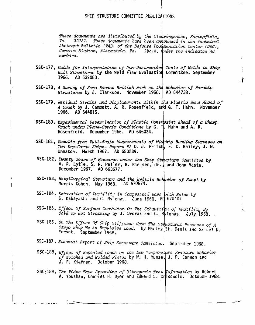
1These doowment6 are dist~ibutedby the Cle ringhouse, SptingfieZd,Vu. 221s1, These doczmznatshava been owaced in the TechnicalAbs&m% Bulletin (TAB) of the Defense Doe en.tai%onCente? (DDC)~Cwnaon Station, Alexandria, Vu. 22314, de~ the indiea~ed ADnumbers.
!Guide fop Int.erpmtation of Non-Deotruci%v Tests of Welds in ShipHUZ2 structures by the Meld Flaw Evaluatio Committee. September
$
1966. AD 639053. .m~’
1A Survey of$oma Recent British Wo~k on th Behuviim of Warsh@S*rwtures by J. Clarkson. November 1966. AD 644738.
ResiduaZ Strains and Displacements within
t
e PZastic Zone Ahead ofA Crack by J. Cammett, A. R. Rosenfield, a G, T. Hahn, November1966. AD 644815.
E~e~imentil- Determination of Pkstie Con8
r
in+ Ahead ofa SharpCrack &r PZane-Strain Conditions by G. . Hahn and A. R.Rosenfield. December 1966. AD 646034.
1Results from FulLScaJe Measurements of% hip Bend<ng Streeees on~0 Dry-C@go Sh@s- Rqort #2 D. J. Fritch, F. C. Bailey~ J. W.Wheaton. March 1967. AD 650239.
TTwnty Years of Research under the Ship St oture Committee byA. R. Lytle, S. R. Heller, R. Nielsen, Jr. and John Vasta.December 1967. AD 663677.
TAfetaZZurgicaZ Struettwe and the &it62e Be vior ofSteeZ byMorris Cohen. May 1968. AD 670574.
t
Exhau,qtionof DuctiZiQ in Compressed BaFc ith Holes byS. Kabayashi and C. Mylonas. June 1968. A 670487
1Effect Of Supfaee Condition On l% Exhaucti n Of Ductility ByCold or Hot StPaining by J. Dvorak and C. M lonas. July 1968.
?
On The Effeet Of Ship Stiffness Upon The St ctu~al Response of ACa~g~ Ship To An .13qwlsiveLoad, by Manley St. Denis and Samuel N,Fersht. September 1968.
IBiennial l?epo~tof Ship Stzwetu~e Comnittee. September 1968.
Effaet of Repeated Loads m the LmI Tempe?a
r
e Fracture Behmio~of flotc?iedand WeZded plates by W. H. Munse J. P. Cannon andJ. F. Kiefner. October 1968.
!The Video Tape Reeo~ding of Ultrasonic Test rlfomation by RobertA. Youshaw, Charles H. Dyerand Edward L. C “SCUO1O. October 1968.
L—....-—.—.—.—-...—.-,-.—. ~“—— ..,-— .—.— —- —. ,,——. — “-—
Recommended