The Titanium Cannulated LateralEntry Femoral Recon Nail. ExpertNailing System.
Technique Guide
Expert Nailing System

Introduction
Surgical Technique
Product Information
Table of Contents
Titanium Cannulated Lateral Entry 2Femoral Recon Nail Expert System
AO Principles 4
Indications 5
Clinical Cases 6
Preoperative Planning 8
Opening the Femur 12
Insert the Nail 20
Locking Options 25
Proximal Locking–Standard 26
Proximal Locking–Recon 30
Distal Locking 34
End Cap Insertion 39
Implant Removal 41
Implant Specifications 43
Implants 44
Instruments 49
Set Lists 57
Sterilization Parameters 57
Image intensifier control
Synthes

End caps– Prevent ingrowth of tissue and
facilitate nail extraction
– Self-retaining, T40 StarDrive recess foreasy pickup and insertion of end cap
– Cannulated for insertion over a guide wire
– 0 mm end cap sits flush with nail
– 5, 10, 15, and 20 mm end caps extend nail height if nail is overinserted
Thispatientha
ssom
eSy
nth
es®lo
ckin
g
screws with h exalobular in ternal drive
acco
rding
toEN
ISO10664
StarDriveT40
20 mm 15 mm 10 mm 5 mm 0 mm
Titanium Cannulated Lateral Entry Femoral Recon Nail Expert System
2 Synthes Titanium Cannulated Lateral Entry Femoral Recon Nail Expert System
Advanced solutions
Nail features– Design accommodates a lateral entry
site through the greater trochanter
– Anatomic nail design based on afemoral canal study1
– Cannulated nails (from 9 mm to 16 mm diameter) for reamed or unreamed techniques
– Lengths from 300 mm to 480 mm, in 20 mm increments
Improved instrumentation– Easy-to-use instrumentation facilitates
the surgical procedure
– Ball-tip reaming rod can be removedthrough the nail and insertion instruments, eliminating the need for an exchange tube
1. L. Ehmke, B. Polzin, C. Roth, M. Bottlang, “FemoralNailing Through the Trochanter: The Reamer PathwayIndicates A Helical Shape,”Journal of OrthopedicTrauma, Vol. 20, Number 10, November/December2006, p. 668-674.

Synthes 3
Enhanced distal locking options– Oblique distal locking hole offers
enhanced stability of distal fractures
Standard locking screws– Double-lead thread for ease of
insertion
– Thread closer to screw head providesbetter bone purchase in the near cortex and improved stability
– Titanium alloy* for improved mechanical and fatigue properties
– Self-tapping blunt tip
– Self-retaining T25 StarDrive recess allows improved torque transmission,increased resistance to strippingrelative to a hex recess, and securelocking screw pickup
– 5.0 mm diameter for 9 mm to 13 mm nails
– 6.0 mm diameter for 14 mm to 16 mm nails
6.5 mm recon screws– Self-retaining T25 StarDrive recess
– Titanium alloy*
– Self-tapping blunt tip
Thispatientha
ssom
eSy
nth
es®lo
ckin
g
screws with h exalobular in ternal drive
acco
rding
toEN
ISO10664
StarDriveT25
* Titanium-6% aluminum-7% niobium alloy
5.0 mm
6.0 mm
6.5 mm

AO Principles
4 Synthes Titanium Cannulated Lateral Entry Femoral Recon Nail Expert System
In 1958, the AO formulated four basic principles, which havebecome the guidelines for internal fixation in general, andintramedullary nailing in particular2:
Anatomic reductionThe Titanium Cannulated Expert Lateral Entry Femoral ReconNail is designed to fit anatomically in the medullary canal, allowing indirect reduction.
Stable fixationThe intramedullary nail acts as an internal splint that controlsbut does not prevent micromovements of the fragments. Itprovides relative stability that leads to an indirect healingthrough callus formation.
Preservation of blood supplyThe instruments and implants in the Lateral Entry Femoral Recon Nail Expert System permit a percutaneous techniqueand less tissue stripping than other treatment methods. An intramedullary approach results in decreased blood loss compared to plate fixation.
Early, active mobilizationThe titanium cannulated expert lateral entry femoral reconnail provides secure fixation which permits controlled, early,active rehabilitation conducive to optimal recovery.
2. M.E. Müller, M. Allgöwer, R. Schneider, and H. Willenegger: AO Manualof Internal Fixation, 3rd Edition. Berlin: Springer-Verlag. 1991.

Indications
The Lateral Entry Femoral Recon Nail–EX is indicated to stabilize:
– Subtrochanteric fractures
– Ipsilateral neck/shaft fractures
– Femoral shaft fractures
– Impending pathologic fractures
– Malunions and nonunions
Synthes 5

Clinical Cases
6 Synthes Titanium Cannulated Lateral Entry Femoral Recon Nail Expert System
Case 1– Standard locking
– 85-year-old female
– Isolated femoral shaft fracture (AO 32-A1.2)
For simple shaft fractures, two proximal and two distal ML locking screws are normally sufficient to stabilize thefracture. Stability of the distal fragment can be enhanced by the use of a third locking screw in the oblique hole.
Case 2– Recon locking
– 49-year-old male
– Ipsilateral femoral neck and shaft fractures (AO 31-B2, AO 32-B2)
The use of two recon screws (recon locking) ensures optimal stabilization for the treatment of combined femoral neck and shaft fractures.
The distal segment can be stabilized by using two ML lockingscrews. Stability of the distal fragment can be enhanced by the use of a third locking screw in the oblique hole.

Synthes 7
Preoperative Follow-up (1 month after surgery)
Preoperative Follow-up (1 month after surgery)

Preoperative Planning
Use the AO preoperative planner template for the experttitanium cannulated lateral entry femoral recon nail to estimate nail diameter and length.
To estimate nail diameter, place the template on the AP or lateral x-ray of the uninjured femur and measure the diameterof the medullary canal at the narrowest part that will containthe nail.
To estimate nail length, place the template on the AP x-ray ofthe uninjured femur and select the appropriate nail lengthbased on patient anatomy. When selecting nail size, considercanal diameter, fracture pattern, patient anatomy and post-operative protocol.
Note: Templates are available in two sizes: actual size and115% magnification in which the image is enlarged 15% tocorrespond to typical radiographic magnification; however,variations in magnification levels are common.
8 Synthes Titanium Cannulated Lateral Entry Femoral Recon Nail Expert System

Synthes 9
2Reduce fracture
Instrument
394.35* Large Distractor
Perform closed reduction manually by axial traction under image intensifier control. The use of the large distractor may be appropriate in certain circumstances.
1Position patient
Position the patient in the lateral decubitus or supine position on a fracture table or radiolucent operating table.Position the C-arm to allow visualization of the proximal femur in both the AP and lateral planes.
To facilitate access to the medullary canal, abduct the upperpart of the body approximately 10°–15° to the contralateralside and adduct the affected limb by 10°–15°.
10–15°Adduction
Affectedleg
* Also available

Preoperative Planning continued
3Confirm nail length
Instrument
03.010.020 Radiographic Ruler, for Titanium CannulatedFemoral Nails
The required nail length must be determined after reductionof the femoral fracture.
Position the C-arm for an AP view of the proximal femur.With long forceps, hold the ruler alongside the lateral thigh,parallel to and at the same level as the femur. Adjust theruler until the proximal end is at the desired nail insertiondepth. Mark the skin at the proximal end of the ruler.
Move the C-arm to the distal femur. Verify fracture reduction.Align the proximal end of the radiographic ruler to the skinmark, and take an AP image of the distal femur.
Read nail length directly from the ruler image, selecting themeasurement at or just proximal to the epiphyseal scar, or at the chosen insertion depth.
Notes:It is recommended that all fractures be treated with thelongest nail possible, taking into account patient anatomy or a previous implant.
Back-hammering or dynamization to close a fracture gapmust be taken into account when determining the nail length.A shorter nail should be chosen when back-hammering or dynamization is planned. The dynamic slot allows 7 mm of movement.
10 Synthes Titanium Cannulated Lateral Entry Femoral Recon Nail Expert System

4Confirm nail diameter
Instrument
03.010.023 Radiographic Canal Width Estimator
Position the C-arm for an AP or lateral view of the femur atthe level of the isthmus. Hold the radiographic canal widthestimator over the femur so that the diameter gauge is centered over the narrowest part of the medullary canal. Read the estimated diameter measurement on the circular indicator that fills the canal.
Note: If the reamed technique is used, the diameter of thelargest medullary reamer must be a minimum of 1.0 mmlarger than the nail diameter.
Synthes 11

Opening the Femur
1Approach
Palpate the posterior edge of the greater trochanter.
Make a 3 cm incision in line with the central axis of the intramedullary canal in the lateral view, and depending on the anatomy of the patient, 2 cm –5 cm proximal to the tip of the greater trochanter.
2Determine entry point
The insertion point for the nail is approximately 20 mm lateral to the center of the medullary canal. The insertionpoint is 10° lateral to the greater trochanter, as measuredfrom a point 40 mm distal to the lesser trochanter.
The entry point can also be described as lateral to the greatertrochanter at the same level as the superior aspect of thebase of the femoral neck (just above the piriformis fossa).This point can be found by extending a line horizontally fromthe base of the femoral neck to the lateral side of the femur.
12 Synthes Titanium Cannulated Lateral Entry Femoral Recon Nail Expert System
40 mm
10°

3Insert guide wire
Instruments
357.392 17.0 mm/3.2 mm Wire Guide
357.393 3.2 mm Trocar
357.399 3.2 mm Guide Wire
357.410 22.0 mm/17.0 mm Protection Sleeve
Insert the protection sleeve, wire guide and trocar assemblyinto the incision site and to the bone.
Remove the trocar. Insert the guide wire through the wire guide.
The guide wire must be inserted laterally at an angle of 10° to the center of the medullary canal. The tip of the guidewire should be centered in the medullary canal 40 mm distal to the lesser trochanter.
Verify that the guide wire position allows adequate clearanceon the lateral side of the femur for the opening drill bit.
The guide wire is inserted so that it is centered in the lateral view.
Synthes 13

Opening the Femur continued
4Open medullary canal with drill bit and flexiblereamers
Instruments
03.010.028 15.0 mm Cannulated Drill Bit
03.010.029 17.0 mm Cannulated Drill Bit
357.410 22.0 mm/17.0 mm Protection Sleeve
DrillSelect appropriate cannulated drill bit as follows:
Nail diameter Drill bit size
9.0 mm –12.0 mm 15.0 mm
13.0 mm –16.0 mm 17.0 mm
Drill through the protection sleeve. Drill the medullary canal to a depth of 20 mm.
Remove the guide wire, drill bit and protection sleeve.
Note: Dispose of the guide wire. Do not reuse.
ReamProceed to page 17 for the section on reaming. Place the 2.5 mm reaming rod and ream the medullary canal to thedesired diameter.
OpenUsing the flexible reamers,* open the proximal femur to a depth of 80 mm as follows:
Nail diameter Proximal reamer diameter
9.0 mm–12.0 mm 15.0 mm
13.0 mm–16.0 mm 17.0 mm
14 Synthes Titanium Cannulated Lateral Entry Femoral Recon Nail Expert System
20 mm
80 mm
* Found in also available Flexible Reamer Set (105.060)

Alternative technique: Open medullary canal withcannulated drill bits
Alternative instruments
03.010.028 15.0 mm Cannulated Drill Bit
03.010.029 17.0 mm Cannulated Drill Bit
357.410 22.0 mm/17.0 mm Protection Sleeve
Using the protection sleeve and cannulated drill bit, drill overthe 3.2 mm guide wire until the drill stop on the drill reachesthe protection sleeve.
Monitor progress of the drill with the image intensifier. Ensure that the lateral and medial cortical walls are not compromised. Adjust the guide wire if necessary.
Remove the guide wire, protection sleeve and drill bit.
Note: Dispose of the guide wire. Do not reuse.
Alternative instruments
03.010.165 15.0 mm Cannulated Flexible Drill Bit, large quick coupling
03.010.167 17.0 mm Cannulated Flexible Drill Bit, large quick coupling
357.410 22.0 mm/17.0 mm Protection Sleeve
Insert the guide wire approximately 20 mm into the proximal femur.
Using the cannulated flexible drill bit, ream to the level of the lesser trochanter.
Remove the guide wire and drill bit.
Note: Dispose of the guide wire. Do not reuse.
Synthes 15

Opening the Femur continued
4 Alternative technique: Open medullary canal with awl continued
Alternative instruments
03.010.041 14.0 mm Cannulated Awl
357.399 3.2 mm Guide Wire
Place the cannulated awl over the guide wire and open themedullary canal. Use a twisting motion to advance the awl to a depth of approximately 80 mm.
Remove the guide wire and awl.
Note: Dispose of the guide wire. Do not reuse.
16 Synthes Titanium Cannulated Lateral Entry Femoral Recon Nail Expert System

Synthes 17
5Reaming the medullary canal (optional)
Required set
150.060 Flexible Reamer Set for IM Nails
Instruments
03.010.024 Holding Device, for Guide Wires andReaming Rods
03.010.093 Reaming Rod Push Rod
351.706S 2.5 mm Reaming Rod, with ball tip, 950 mm
351.707S 2.5 mm Reaming Rod, with ball tip andextension, 950 mm
351.708S 2.5 mm Reaming Rod, with ball tip, 1150 mm
351.782 Holding Forceps
360.243 Handle, for 12.0 mm Tapered IntramedullaryReduction Tool
360.244 Shaft, for 12.0 mm Tapered IntramedullaryReduction Tool
360.251 7.5 mm Intramedullary Reduction Tool
393.105 Small Universal T-Handle Chuck
If necessary, enlarge the femoral canal with the medullaryreamer to the desired diameter.
Check fracture reduction under image intensifier. Use the 7.5 mm reduction tool or 12.0 mm reduction tool assemblyto facilitate reduction.

Opening the Femur continued
18 Synthes Titanium Cannulated Lateral Entry Femoral Recon Nail Expert System
5Reaming the medullary canal (optional) continued
Inserting the reaming rodInsert the reaming rod with ball tip into the medullary canal,using the holding device or T-handle chuck to the desired insertion depth.
If using the holding device, set thumb switch to the ‘RELEASE’ or ‘LOCK’ position (figure 1).
Insert guide wire/reaming rod. Apply force to the lever with your hand as far from the pivot as possible (figure 2).
RELEASE position: Clamp will free the wire upon releasingthe handle (figure 3).
LOCK position: Clamp will retain the wire. The device willclick when set to the LOCK position.
Note: To release a wire retained in the LOCK position, applyforce to the lever on its lower end, then push the thumbswitch to the RELEASE position. This relaxes the engagementof the locking mechanism by deflecting the lever.
To bend reaming rods, insert extension tip into ‘reaming rod’hole on the back of the handle. Bend until the rod contactsthe handle. This allows a 15º bend on the reaming rod tip(figure 4).
Figure 1 Figure 2
Figure 3 Figure 4

Synthes 19
ReamingStarting with the 8.5 mm diameter reaming head, ream to a diameter a minimum of 1.0 mm greater than the nail diameter. Ream in 0.5 mm increments and advance thereamer with steady, moderate pressure. Do not force thereamer. Partially retract the reamer often to clear debris from the medullary canal.
The holding forceps can be used to control the rotation of the reaming rod.
Note: The reaming rod with ball tip can be removed through all cannulated lateral entry femoral nails. Reamingrod exchange is not required.
OptionUse the reaming rod push rod to help retain the reamingrod during reamer extraction.

Inserting the Nail
20 Synthes Titanium Cannulated Lateral Entry Femoral Recon Nail Expert System
1Assemble insertion instruments
Instruments
03.010.044 Cannulated Connecting Screw, for Standard Insertion Handle
03.010.045 Standard Insertion Handle
03.010.092 Ball Hex Screwdriver, 8 mm
Match the tang on the handle to the notch in the titaniumcannulated lateral entry femoral recon nail .
Place the connecting screw into the insertion handle andthread it into the proximal nail end using the 8 mm ball hex screwdriver.
The recon nails are labeled ‘left’ or ‘right’ on the proximalnail end.

Synthes 21
Alternative instrument
03.010.093 Reaming Rod Push Rod
Optionally, slide the connecting screw onto the reaming rodpush rod. Slide the assembly through the insertion handleand match the tang on the handle to the nail. Tighten usingthe hex on the reaming rod push rod.
Secure the assembly using the 8 mm ball hex screwdriver.

22 Synthes Titanium Cannulated Lateral Entry Femoral Recon Nail Expert System
2 Insert nail
Instruments
03.010.047 Driving Cap with Handle Adapter
03.010.056 Slide/Fixed Hammer, 700 grams
03.010.092 Ball Hex Screwdriver, 8 mm
321.17 Pin Wrench, 4.5 mm
321.20 Ratchet Wrench, 11 mm
357.22 Hammer Guide
357.398 Cannulated Shaft with 8 mm hex
Slide the driving cap into the groove on the insertion handleand secure it using the 11 mm ratchet wrench. If patientanatomy allows, attach the driving cap in the medial position.
Orient the insertion handle in an anterior position. Use the C-arm to verify fracture reduction. Insert the nail as far as possible.
The nail rotates approximately 90° during insertion. The insertion handle rotates from an anterior to a lateral positionduring insertion of the last one-third of the nail length. If thenail does not rotate to the lateral position, remove the nail andreinsert with the handle slightly lateral to the sagittal plane.
Monitor nail passage across the fracture, and control in two planes to avoid malalignment.
Note: Do not mount the aiming arm until the nail has beencompletely inserted.
If desired, insert the nail using light hammer blows.
Lock the head of the hammer in place by tightening the nutonto the threads located below the hammer head. Use thepin wrench if necessary. Strike the driving cap directly.
Inserting the Nail continued
Synthes 23
Optionally, the hammer guide can be threaded onto the driving cap and the hammer can be used as a slide hammer.Loosen the nut from the threads located below the hammerhead and secure the nut onto the threads located above the handle.
Note: If nail insertion is difficult, choose a smaller diameternail or ream the intramedullary canal to a larger diameter.
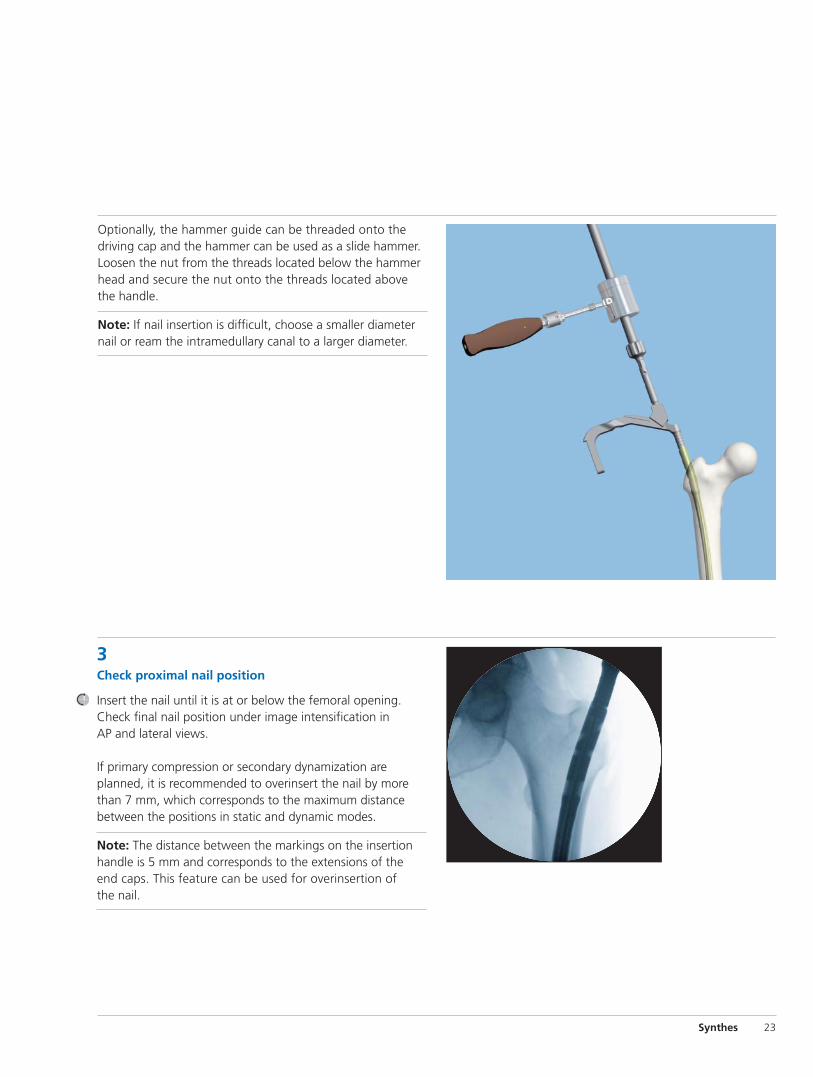
3Check proximal nail position
Insert the nail until it is at or below the femoral opening.Check final nail position under image intensification in AP and lateral views.
If primary compression or secondary dynamization areplanned, it is recommended to overinsert the nail by morethan 7 mm, which corresponds to the maximum distance between the positions in static and dynamic modes.
Note: The distance between the markings on the insertionhandle is 5 mm and corresponds to the extensions of theend caps. This feature can be used for overinsertion of the nail.

24 Synthes Titanium Cannulated Lateral Entry Femoral Recon Nail Expert System
Inserting the Nail continued
4Check distal nail location
Use image intensification to ensure the nail is centered in both AP and lateral views. Verify fracture alignment.
Remove the reaming rod.

Synthes 25
Locking Options
Proximal locking with two recon screwsProximal locking with static locking optionProximal locking with 120° locking screw and dynamic locking option

26 Synthes Titanium Cannulated Lateral Entry Femoral Recon Nail Expert System
Proximal Locking—Standard
1Choose appropriate locking screws and instruments
Use the correct locking screw, drill sleeve, trocar and drill bit for the selected nail diameter, as shown on the table.
Nail diameter Locking screws Protection sleeve Drill sleeve Trocar Calibrated drill bit
9.0 mm– 5.0 mm 12.0 mm/8.0 mm 8.0 mm/ 4.2 mm 4.2 mm 4.2 mm13.0 mm (green) (03.010.063) (03.010.065) (03.010.070) (03.010.061)(green)
14.0 mm– 6.0 mm 12.0 mm/8.0 mm 8.0 mm/5.0 mm 5.0 mm 5.0 mm16.0 mm (aqua) (03.010.063) (03.010.066) (03.010.071) (03.010.062)(aqua)
For standard locking, three targeted proximal locking options are possible:
1 120° antegrade locking
2 Dynamic locking (LM)
3 Static locking (LM)
For immediate dynamization, insert one proximal lockingscrew through the dynamic slot. If dynamization may be required in the future, use the dynamic locking optionwith the 120° antegrade locking hole.
1
2
3

Synthes 27
2Mount aiming arm
Instruments
03.010.048 Recon Locking Aiming Arm, for Lateral Entry Femoral Nails–EX
03.010.092 Ball Hex Screwdriver, 8 mm
Confirm that the nail is securely connected to the insertionhandle using the 8 mm ball hex screwdriver. Mount the aiming arm to the insertion handle.
3Insert trocar combination
Instruments
03.010.063 12.0 mm/8.0 mm Protection Sleeve
03.010.065 8.0 mm/4.2 mm Drill Sleeve
03.010.066 8.0 mm/5.0 mm Drill Sleeve
03.010.070 4.2 mm Trocar
03.010.071 5.0 mm Trocar
Insert the three-part trocar combination (protection sleeve,corresponding drill sleeve and trocar) through the desiredhole in the aiming arm, make a stab incision and insert thetrocar to the bone. Remove the trocar.

Proximal Locking— Standard continued
28 Synthes Titanium Cannulated Lateral Entry Femoral Recon Nail Expert System
4Drill and determine locking screw length
Instruments
03.010.061 4.2 mm Three-Fluted Drill Bit, quick coupling,330 mm, 100 mm calibration
03.010.062 5.0 mm Three-Fluted Drill Bit, quick coupling,330 mm, 100 mm calibration
Ensure that the drill sleeve is pressed firmly to the lateral cortex. Using the appropriate drill bit (4.2 mm for 5.0 mmlocking screws or 5.0 mm for 6.0 mm locking screws), drillthrough both cortices until the tip of the drill bit just penetrates the far cortex.
Confirm drill bit position.
Ensure that the drill sleeve is pressed firmly to the lateral cortex and read the measurement from the calibrated drill bit at the back of the drill sleeve. This measurement corre-sponds to the appropriate length locking screw. Remove the drill bit and drill sleeve.
3Insert trocar combination continued
If using the 120° antegrade locking option, insert the trocarcombination through the hole labeled 120° on the insertionhandle.
Note: Do not exert forces on the aiming arm, protectionsleeve, drill sleeves and drill bits. These forces may preventaccurate targeting through the proximal locking holes anddamage the drill bits.

Synthes 29
Alternative instrument
03.010.072 Depth Gauge for Locking Screws
After drilling both cortices, remove the drill bit and drill sleeve.
Disassemble the depth gauge into two parts: the outersleeve and the measuring device with hook. Insert the measuring device into the protection sleeve. Make sure that the hook grasps the far cortex.
Ensure that the protection sleeve is firmly pressed against the lateral cortex.
Read the measurement from the back of the protectionsleeve, which indicates the appropriate length locking screw.
5Insert locking screw
Instrument
03.010.150 Star/HexDrive Screwdriver, T25, 3.5 mm hex
Insert the appropriate length locking screw through the protection sleeve using the Star/HexDrive screwdriver. Verify locking screw length under image intensification.
The tip of the locking screw should not project more than 2 mm to 4 mm beyond the far cortex.
Note: A groove on the screwdriver provides a rough indication that the locking screw is fully inserted through the sleeve.
Repeat for the second proximal locking screw if desired.

Proximal Locking—Recon
1Confirm nail position
In the AP view, adjust the nail insertion depth to ensure thatthe two recon screws can be placed into the femoral head.
Adjust nail position for correct anteversion.
2Insert guide wires for recon screws
Instruments
03.010.075 11.5 mm/8.5 mm Protection Sleeve, for Recon Locking
03.010.076 8.5 mm/3.2 mm Wire Guide, for Recon Locking
03.010.077 3.2 mm Trocar, for Recon Locking
357.399 3.2 mm Guide Wire, 400 mm
Insert both three-part trocar combinations (protection sleeve,drill sleeve, and trocar) through the aiming arm. Make a stabincision and insert the trocars to the bone.
Following the arrows on the aiming arm, rotate the cams so that the protection sleeves are locked in the aiming arm.This will ensure proper measurement for the recon screws.
30 Synthes Titanium Cannulated Lateral Entry Femoral Recon Nail Expert System

Synthes 31
Remove the inferior trocar.
Insert a guide wire into the femoral head approximately 5 mm from subchondral bone. Check guide wire placementradiographically in both AP and lateral views.
Remove the superior trocar.
Insert the second guide wire into the femoral head approxi-mately 5 mm from subchondral bone. Check the guide wireplacement in both AP and lateral views.
Note: Do not exert forces on the aiming arm, protectionsleeves, and drill sleeves. These forces may prevent accuratetargeting through the locking holes.

Proximal Locking—Recon continued
3Determine length and drill for inferior recon screw
Instruments
03.010.078 4.5 mm/6.5 mm Stepped Drill Bit, largequick coupling, 485 mm
03.010.079 Drill Stop, for 4.5 mm/6.5 mm Stepped Drill Bit
03.010.085 Specialty Locking Measuring Device, for Titanium Femoral Nails–EX
Measure inferior screw.
Ensure the protection sleeve is pressed firmly to the lateralcortex. Remove the drill sleeve and insert the direct measur-ing device over the guide wire into the protection sleeve tothe bone. Read the length of the required recon screw directly on the measuring device.
Remove the measuring device and the inferior guide wire.
Attach the drill stop to the stepped drill bit for the appropri-ate length screw.
Guide the stepped drill bit through the protection sleeve to the bone. Drill to the stop.
32 Synthes Titanium Cannulated Lateral Entry Femoral Recon Nail Expert System

Synthes 33
4Insert inferior recon screw
Instrument
03.010.108 StarDrive Screwdriver T25, self-retaining, long
Insert the appropriate recon screw through the protectionsleeve into the femoral head, using the long T25 StarDrivescrewdriver. Verify the position of the locking screw underimage intensification in both planes.
A groove on the screwdriver indicates when the recon screwis fully inserted.
Repeat steps 3 and 4 for the second, superior recon screw.

34 Synthes Titanium Cannulated Lateral Entry Femoral Recon Nail Expert System
Distal Locking
1Distal locking
There are three distal locking options:– Two transverse, lateral to medial holes
– One oblique locking hole for enhanced stability of distal fractures
Nail diameter Locking screws Drill bit
9.0 mm– 5.0 mm 4.2 mm13.0 mm (green) (03.010.101) or(green) (03.010.104)
14.0 mm– 6.0 mm 5.0 mm16.0 mm (aqua) (03.010.102) or(aqua) (03.010.105)
If using the oblique locking hole, insert at least one transverseLM screw prior to rotating the leg for the oblique lockinghole. This will maintain rotational alignment.

2Align image
Check the reduction and correct alignment of the fragmentsand leg length before locking the nail.
Align the C-arm with the hole in the nail closest to the fracture until a perfect circle is visible in the center of the screen.
3Determine incision point
Place a scalpel blade on the skin over the center of the hole to mark the incision point and make a stab incision.
Synthes 35

Distal Locking continued
36 Synthes Titanium Cannulated Lateral Entry Femoral Recon Nail Expert System
4Drill
Instruments
03.010.101 4.2 mm Three-Fluted Drill Bit, quick coupling,145 mm, for Radiolucent Drive
03.010.102 5.0 mm Three-Fluted Drill Bit, quick coupling,145 mm, for Radiolucent Drive
Using the radiolucent drive under image intensification, insert the tip of the appropriate drill bit through the incisionand down to the bone.
Incline the drive so that the tip of the drill bit is centered overthe locking hole. The drill bit should almost completely fillthe circle of the locking hole. Hold the drill bit in this positionand drill through both cortices.
Technique tip: For greater drill bit control, discontinue drillpower after perforating the near cortex. Manually guide thedrill bit through the nail before resuming power to drill the far cortex.
Alternative instruments
03.010.104 4.2 mm Three-Fluted Drill Bit, quick coupling,145 mm
03.010.105 5.0 mm Three-Fluted Drill Bit, quick coupling,145 mm
If there is no radiolucent drive available and locking is performed with the standard freehand technique, use the 4.2 mm or 5.0 mm three-fluted drill bit, quick coupling.

Synthes 37
5Determine locking screw length
Instruments
03.010.101 4.2 mm Three-Fluted Drill Bit, quick coupling,145 mm, for Radiolucent Drive
03.010.102 5.0 mm Three-Fluted Drill Bit, quick coupling,145 mm, for Radiolucent Drive
03.010.104 4.2 mm Three-Fluted Drill Bit, quick coupling,145 mm
03.010.105 5.0 mm Three-Fluted Drill Bit, quick coupling,145 mm
03.010.106 Direct Measuring Device, for Locking Screwsto 100 mm, for IM Nails
Stop drilling immediately after penetrating the far cortex.Disassemble the power drive or radiolucent drive from thedrill bit.
Ensure the correct position of the drill bit in regard to the far cortex of the femur.
Place the direct measuring device onto the drill bit. Read thegraduation of the measuring device at the end of the drill bit.This corresponds to the appropriate locking screw length.
Note: Drill bit location with respect to the far cortex is critical for measuring the appropriate locking screw length.
Alternative instrument
03.010.072 Depth Gauge for Locking Screws to 100 mm,for IM Nails
Measure the locking screw length using the depth gauge for locking screws. Ensure the outer sleeve is in contact withthe bone and the hook grasps the far cortex.
Read the locking screw length directly from the depth gaugeat the back of the outer sleeve.

Distal Locking continued
38 Synthes Titanium Cannulated Lateral Entry Femoral Recon Nail Expert System
6Insert locking screw
Instruments
03.010.112 Holding Sleeve with Locking Device
03.010.150 Star/HexDrive Screwdriver, T25, 3.5 mm hex
Insert the locking screw using the screwdriver and the holding sleeve with locking device, if desired.
Verify locking screw length under image intensification. The screw tip should be about 2 mm beyond the far cortex.If needed, a second locking screw may be inserted using the same technique.
Use the holding sleeve as described below:
Insert the holding sleeve onto the shaft of the screwdriverand place the tip of the screwdriver in the recess of the locking screw (figure A).
Push the holding sleeve in the direction of the locking screw.The sleeve now holds the locking screw.
Lock the holding sleeve by tightening it counterclockwise(figure B). After insertion of the locking screw, release the holding sleeve by loosening it clockwise and pulling backward (figure C).
Figure A
Figure B
Figure C

Synthes 39
End Cap Insertion
7Insert end cap
Instruments
03.010.110 Cannulated StarDrive Screwdriver, T40
357.399 3.2 mm Guide Wire, 400 mm
The end caps for femoral nails are available in extensionlengths of 0 mm, 5 mm, 10 mm, 15 mm, and 20 mm. Theyfulfill two functions: they prevent bone ingrowth into thenail and they extend the nail height if it is overinserted.
The end caps are cannulated for use over a guide wire, if necessary.
Remove the nail insertion instruments.
Optionally, for insertion of the 0 mm end cap, remove theconnecting screw only. The insertion handle can remain tohelp align the end cap to the top of the nail. The 0 mm endcap fits through the barrel of the insertion handle.
Insert the guide wire into the proximal end of the nail.
Engage the end cap with the cannulated screwdriver by exert-ing axial pressure. To prevent cross-threading, align the endcap with the nail axis and turn the end cap counterclockwise,until the thread of the end cap aligns with that of the nail.
Turn the end cap clockwise to thread the end cap into the nail.
Remove the guide wire and screwdriver.

End Cap Insertion continued
Alternative instruments
03.010.111 Cannulated StarDrive Screwdriver, T40, with lever handle
321.20 Ratchet Wrench, 11 mm
Alternatively, the cannulated StarDrive screwdriver, T40, with lever handle may be used with the 11 mm ratchetwrench to insert the end cap.
40 Synthes Titanium Cannulated Lateral Entry Femoral Recon Nail Expert System

Implant Removal
Synthes 41
1Remove end cap and locking screws
Instruments
03.010.110 Cannulated StarDrive Screwdriver, T40
03.010.112 Holding Sleeve with Locking Device
03.010.150 Star/HexDrive Screwdriver, T25, 3.5 mm hex
357.399 3.2 mm Guide Wire
Implant removal is an optional procedure.
Clear the StarDrive socket of the end cap and the locking implants of any ingrown tissue. Insert the guide wire for easy aligning of the screwdriver into the cannulated end cap. Remove the end cap using the T40 screwdriver.
Remove all locking screws except one proximal locking screw.
2Attach extraction screw and hammer guide
Instruments
03.010.150 Star/HexDrive Screwdriver, T25, 3.5 mm hex
357.133 Extraction Screw
357.22 Hammer Guide, for Slide Hammer
Before removing the final locking screw, screw the extractionscrew into the nail and tighten it. The locking screw will prevent nail rotation as the extraction screw is tightened.
Attach the hammer guide to the extraction screw.
Remove the remaining locking screw with the screwdriver.

Implant Removal continued
3Remove nail
Instrument
03.010.056 Slide/Fixed Hammer, 700 grams
Extract the nail by applying gentle blows with the hammer.
Note: The nail will rotate about 90°, similar to the movementduring the insertion.
42 Synthes Titanium Cannulated Lateral Entry Femoral Recon Nail Expert System

Implant Specifications
Synthes 43
Lateral Entry Femoral Recon Nail–EX– Available for left or right femur
– Anatomic nail design based on afemoral canal tracing study3
Material– Titanium-6% aluminum-7% niobium
alloy
Diameters– 9.0 mm to 16.0 mm, cannulated
– 9.0 mm through 12.0 mm nails—13.5 mm proximal diameter
– 13.0 mm through 16.0 mm nails—16.0 mm proximal diameter
Colors– 9.0 mm through 13.0 mm (light green)
– 14.0 mm through 16.0 mm (aqua)
Lengths– 300 mm through 480 mm in 20 mm
increments
Cross Section– 9.0 mm through 16.0 mm diameter
nails—helical fluted
Proximal Locking– Two recon locking holes
(130° neck/shaft angle)
– Dynamization slot (LM)
– Static transverse locking hole (LM)
– 120° antegrade locking hole
Distal Locking– Two transverse locking holes (LM)
– One oblique locking hole (LM)
3. L.Ehmke, et al.
20.6 mm
47 mm60.6 mm
7 mm
13 mmRecon locking
Static transverse
Dynamic transverse
120° antegrade
12 mm
42 mm27 mm
LM
Oblique
LM

44 Synthes Titanium Cannulated Lateral Entry Femoral Recon Nail Expert System
Implants
Length 9 mm dia. 9 mm dia.(mm) right left
300 04.003.240S 04.003.241S
320 04.003.244S 04.003.245S
340 04.003.248S 04.003.249S
360 04.003.252S 04.003.253S
380 04.003.256S 04.003.257S
400 04.003.260S 04.003.261S
420 04.003.264S 04.003.265S
440 04.003.268S 04.003.269S
460 04.003.272S 04.003.273S
480 04.003.276S 04.003.277S
Length 11 mm dia. 11 mm dia.(mm) right left
300 04.003.440S 04.003.441S
320 04.003.444S 04.003.445S
340 04.003.448S 04.003.449S
360 04.003.452S 04.003.453S
380 04.003.456S 04.003.457S
400 04.003.460S 04.003.461S
420 04.003.464S 04.003.465S
440 04.003.468S 04.003.469S
460 04.003.472S 04.003.473S
480 04.003.476S 04.003.477S
Length 13 mm dia. 13 mm dia.(mm) right left
300 04.003.640S 04.003.641S
320 04.003.644S 04.003.645S
340 04.003.648S 04.003.649S
360 04.003.652S 04.003.653S
380 04.003.656S 04.003.657S
400 04.003.660S 04.003.661S
420 04.003.664S 04.003.665S
440 04.003.668S 04.003.669S
460 04.003.672S 04.003.673S
480 04.003.676S 04.003.677S
Length 10 mm dia. 10 mm dia.(mm) right left
300 04.003.340S 04.003.341S
320 04.003.344S 04.003.345S
340 04.003.348S 04.003.349S
360 04.003.352S 04.003.353S
380 04.003.356S 04.003.357S
400 04.003.360S 04.003.361S
420 04.003.364S 04.003.365S
440 04.003.368S 04.003.369S
460 04.003.372S 04.003.373S
480 04.003.376S 04.003.377S
Length 12 mm dia. 12 mm dia.(mm) right left
300 04.003.540S 04.003.541S
320 04.003.544S 04.003.545S
340 04.003.548S 04.003.549S
360 04.003.552S 04.003.553S
380 04.003.556S 04.003.557S
400 04.003.560S 04.003.561S
420 04.003.564S 04.003.565S
440 04.003.568S 04.003.569S
460 04.003.572S 04.003.573S
480 04.003.576S 04.003.577S
Titanium Cannulated Lateral Entry Femoral Recon Nails–EX, sterile (green)

Synthes 45
Length 14 mm dia. 14 mm dia.(mm) right left
300 04.003.740S 04.003.741S
320 04.003.744S 04.003.745S
340 04.003.748S 04.003.749S
360 04.003.752S 04.003.753S
380 04.003.756S 04.003.757S
400 04.003.760S 04.003.761S
420 04.003.764S 04.003.765S
440 04.003.768S 04.003.769S
460 04.003.772S 04.003.773S
480 04.003.776S 04.003.777S
Length 15 mm dia. 15 mm dia.(mm) right left
300 04.003.840S 04.003.841S
320 04.003.844S 04.003.845S
340 04.003.848S 04.003.849S
360 04.003.852S 04.003.853S
380 04.003.856S 04.003.857S
400 04.003.860S 04.003.861S
420 04.003.864S 04.003.865S
440 04.003.868S 04.003.869S
460 04.003.872S 04.003.873S
480 04.003.876S 04.003.877S
Length 16 mm dia. 16 mm dia.(mm) right left
300 04.003.940S 04.003.941S
320 04.003.944S 04.003.945S
340 04.003.948S 04.003.949S
360 04.003.952S 04.003.953S
380 04.003.956S 04.003.957S
400 04.003.960S 04.003.961S
420 04.003.964S 04.003.965S
440 04.003.968S 04.003.969S
460 04.003.972S 04.003.973S
480 04.003.976S 04.003.977S
Titanium Cannulated Lateral Entry Femoral Recon Nails–EX, sterile (aqua)

Implants continued
5.0 mm Titanium Locking Screws◊, with T25 StarDriverecess, for IM Nails (light green)
– Titanium alloy*
– Lengths: 26 mm– 80 mm (2 mm increments)85 mm–100 mm (5 mm increments)
– 4.3 mm core diameter
– Fully threaded
– Self-tapping, blunt tip
– T25 StarDrive recess for improved torque transmission and self-retention on screwdriver
Length Length(mm) (mm)
04.005.516 26 04.005.548 5804.005.518 28 04.005.550 6004.005.520 30 04.005.552 6204.005.522 32 04.005.554 6404.005.524 34 04.005.556 6604.005.526 36 04.005.558 6804.005.528 38 04.005.560 7004.005.530 40 04.005.562 7204.005.532 42 04.005.564 7404.005.534 44 04.005.566 7604.005.536 46 04.005.568 7804.005.538 48 04.005.570 8004.005.540 50 04.005.575 8504.005.542 52 04.005.580 9004.005.544 54 04.005.585 9504.005.546 56 04.005.590 100
46 Synthes Titanium Cannulated Lateral Entry Femoral Recon Nail Expert System
◊ Available nonsterile or sterile-packed. Add “S” to catalog number to order sterile product.
* Titanium-6% aluminum-7% niobium alloy

Synthes 47
◊ Available nonsterile or sterile-packed. Add “S” to catalog number to order sterile product.
* Titanium-6% aluminum-7% niobium alloy
6.0 mm Titanium Locking Screws◊, with T25 StarDriverecess, for IM Nails (aqua)
– Titanium alloy*
– Lengths: 26 mm–60 mm (2 mm increments)64 mm–80 mm (4 mm increments)85 mm–125 mm (5 mm increments)
– 4.8 mm core diameter
– Self-tapping tip
– T25 StarDrive recess for improved torque transmission and self-retention on screwdriver.
Length (mm)
04.005.616 2604.005.618 2804.005.620 3004.005.622 3204.005.624 3404.005.626 3604.005.628 3804.005.630 4004.005.632 4204.005.634 4404.005.636 4604.005.638 4804.005.640 5004.005.642 5204.005.644 5404.005.646 56
Length (mm)
04.005.648 5804.005.650 6004.005.654 6404.005.658 6804.005.662 7204.005.666 7604.005.670 8004.005.675 8504.005.680 9004.005.685 9504.005.690 10004.005.691 10504.005.692 11004.005.693 11504.005.694 12004.005.695 125

20 mm 15 mm 10 mm 5 mm 0 mm
Titanium End Caps◊, with T40 StarDrive recess, for Titanium Cannulated Lateral Entry Femoral Recon Nail–EX
– Titanium alloy*
– Protect nail threads from tissue ingrowth
– Cannulated to allow insertion over a guide wire
– T40 StarDrive recess
0 mmSits flush with end of nail
5 mm, 10 mm 15 mm and 20 mm extensionsExtend nail height if nail is overinserted
04.003.000 End Cap, 0 mm extension
12 mm End Caps 16 mm End Capsfor 9 mm– for 13 mm–12 mm nails 16 mm nails04.003.001 04.003.006 5 mm extension04.003.002 04.003.007 10 mm extension04.003.003 04.003.008 15 mm extension04.003.004 04.003.009 20 mm extension
Implants continued
48 Synthes Titanium Cannulated Lateral Entry Femoral Recon Nail Expert System
◊ Available nonsterile or sterile-packed. Add “S” to catalog number to order sterile product.
* Titanium-6% aluminum-7% niobium alloy
6.5 mm Titanium Recon Screws◊, with T25 StarDrive recess
– Titanium alloy*
– Lengths: 60 mm–130 mm (5 mm increments)
– Self-tapping tip
– T25 StarDrive recess for improved torque transmission and self-retention on screwdriver.
Length (mm)
04.003.022 6004.003.023 6504.003.024 7004.003.025 7504.003.026 8004.003.027 8504.003.028 9004.003.029 95
Length (mm)
04.003.030 10004.003.031 10504.003.032 11004.003.033 11504.003.034 12004.003.035 12504.003.036 130

Instruments
Synthes 49
03.010.020 Radiographic Ruler, for Titanium Cannulated Femoral Nails
03.010.023 Radiographic Canal Width Estimator
03.010.024 Holding Device, for Guide Wires and Reaming Rods
03.010.028 15.0 mm Cannulated Drill Bit, large quick coupling, 280 mm
03.010.029 17.0 mm Cannulated Drill Bit, large quick coupling, 280 mm
03.010.041 14.0 mm Cannulated Awl
03.010.044 Connecting Screw, for Standard Insertion Handle

Instruments continued
50 Synthes Titanium Cannulated Lateral Entry Femoral Recon Nail Expert System
03.010.045 Standard Insertion Handle
03.010.047 Driving Cap with Handle Adapter
03.010.048 Recon Locking Aiming Arm, for Lateral Entry Femoral Recon Nails–EX
03.010.056 Slide/Fixed Hammer, 700 grams
03.010.061◊ 4.2 mm Three-Fluted Drill Bit, quick coupling,330 mm, 100 mm calibration
03.010.062◊ 5.0 mm Three-Fluted Drill Bit, quick coupling,330 mm, 100 mm calibration
03.010.063 12.0 mm/8.0 mm Protection Sleeve
◊ Available nonsterile or sterile-packed. Add “S” to catalog number to order sterile product.

Synthes 51
03.010.065 8.0 mm/4.2 mm Drill Sleeve
03.010.066 8.0 mm/5.0 mm Drill Sleeve
03.010.070 4.2 mm Trocar
03.010.071 5.0 mm Trocar
03.010.072 Depth Gauge, for Locking Screws to 100 mm
03.010.075 11.5 mm/8.5 mm Protection Sleeve, for Recon Locking
03.010.076 8.5 mm/3.2 mm Wire Guide, for Recon Locking

Instruments continued
03.010.077 3.2 mm Trocar, for Recon Locking
03.010.078 4.5 mm/6.5 mm Stepped Drill Bit, largequick coupling, 485 mm
03.010.079 Drill Stop, for 4.5 mm/6.5 mm Stepped Drill Bit
03.010.080 Tap for 6.5 mm Recon Screws
03.010.085 Specialty Locking Measuring Device, for Titanium Femoral Recon Nail–EX
03.010.092 Ball Hex Screwdriver, 8 mm
03.010.093 Reaming Rod Push Rod, with ball handle
52 Synthes Titanium Cannulated Lateral Entry Femoral Recon Nail Expert System

Synthes 53
03.010.109 StarDrive Screwdriver Shaft, T25, self-retaining,quick coupling, 280 mm
03.010.101◊ 4.2 mm Three-Fluted Drill Bit, quick coupling,for Radiolucent Drive
03.010.102◊ 5.0 mm Three-Fluted Drill Bit, quick coupling,for Radiolucent Drive
03.010.104◊ 4.2 mm Three-Fluted Drill Bit, quick coupling,needle point, 145 mm
03.010.105◊ 5.0 mm Three-Fluted Drill Bit, quick coupling,needle point, 145 mm
03.010.106 Direct Measuring Device, for Locking Screwsto 100 mm
03.010.108 Stardrive Screwdriver, T25, self-retaining, long
◊ Available nonsterile or sterile-packed. Add “S” to catalog number to order sterile product.

Instruments continued
54 Synthes Titanium Cannulated Lateral Entry Femoral Recon Nail Expert System
321.17 4.5 mm Pin Wrench, 120 mm
03.010.110 Cannulated StarDrive Screwdriver, T40, self-retaining
03.010.111 Cannulated StarDrive Screwdriver, T40, with lever handle, self-retaining
03.010.150 Star/HexDrive Screwdriver, T25, 3.5 mm hex,self-retaining
03.010.151 Star/HexDrive Screwdriver Shaft, T25, 3.2 mm hex, self-retaining, 165 mm
03.010.152 Star/HexDrive Screwdriver Shaft, T25, 3.5 mm hex, self-retaining, 280 mm
03.010.112 Holding Sleeve, with Locking Device

321.20 Ratchet Wrench, 11 mm width across flats
Synthes 55
357.133 Extraction Screw
357.22 Hammer Guide
357.392 17.0 mm/3.2 mm Wire Guide, 161 mm
357.393 3.2 mm Trocar, 172 mm
357.398 Cannulated Shaft with 8 mm hex, 125 mm
357.399 3.2 mm Guide Wire, 400 mm

56 Synthes Titanium Cannulated Lateral Entry Femoral Recon Nail Expert System
Instruments continued
357.410 22.0 mm/17.0 mm Protection Sleeve
360.243 Handle, for 12.0 mm Tapered IntramedullaryReduction Tool
360.244 Shaft, for 12.0 mm Tapered Intramedullary Reduction Tool
360.251 7.5 mm Intramedullary Reduction Tool, 460 mm
393.105 Small Universal Chuck with T-Handle

Synthes 57
Lateral Entry Femoral Nail Recon–EX Instrument Set (01.003.300)
Graphic Case69.003.300 Titanium Lateral Entry Femoral Recon Nail–EX
Instrument Set Graphic Case
Instruments03.010.020 Radiographic Ruler, for Titanium Cannulated
Femoral Nails
03.010.023 Radiographic Canal Width Estimator, for IM Nails
03.010.024 Holding Device, for Guide Wires andReaming Rods
03.010.028 15.0 mm Cannulated Drill Bit, large quickcoupling, 280 mm
03.010.029 17.0 mm Cannulated Drill Bit, large quickcoupling, 280 mm
03.010.041 14.0 mm Cannulated Awl
03.010.044 Cannulated Connecting Screw, for Standard Insertion Handle, 2 ea.
03.010.045 Standard Insertion Handle
03.010.047 Driving Cap with Handle Adapter
03.010.048 Recon Locking Aiming Arm, for Lateral Entry
Femoral Nail–Recon EX
03.010.056 Slide/Fixed Hammer, 700 Grams
03.010.061 4.2 mm Three-Fluted Drill Bit, quick coupling,330 mm, 100 mm calibration, 2 ea.
03.010.062 5.0 mm Three-Fluted Drill Bit, quick coupling,330 mm, 100 mm calibration, 2 ea.
03.010.063 12.0 mm/8.0 mm Protection Sleeve, 188 mm
03.010.065 8.0 mm/4.2 mm Drill Sleeve, 200 mm
03.010.066 8.0 mm/5.0 mm Drill Sleeve, 200 mm
03.010.070 4.2 mm Trocar, 210 mm
03.010.071 5.0 mm Trocar, 210 mm
03.010.072 Depth Gauge for Locking Screws, to 100 mm,for IM Nails
03.010.075 11.5 mm/8.5 mm Protection Sleeve, for Recon Locking
03.010.076 8.5 mm/3.2 mm Wire Guide, for Recon Locking
03.010.077 3.2 mm Trocar, for Recon Locking
03.010.078 4.5 mm/6.5 mm Stepped Drill Bit, large,quick coupling, 485 mm
03.010.080 Tap for 6.5 mm Recon Screws
Sterilization Parameters for Sets (01.003.300 and 01.003.006)This Synthes sets with all additionally available items, as marked in the cases, canbe sterilized by the following parameters. For more information, please refer tographic case package insert.
Method Cycle Temperature Exposure Time
Steam Prevacuum 132°–135°C 8 Minutes(Wrapped) (270°–275°F)
Steam Gravity Displacement 132°–135°C 22 Minutes(Wrapped) (270°–275°F)

Lateral Entry Femoral Nail Recon–EX Instrument Set (01.003.300) continued
360.243 Handle, for 12.0 mm Tapered IntramedullaryReduction Tool
360.244 Shaft, for 12.0 mm Tapered Intramedullary Reduction Tool
360.251 7.5 mm Intramedullary Reduction Tool, 460 mm
393.105 Small Universal Chuck with T-Handle
58 Synthes Titanium Cannulated Lateral Entry Femoral Recon Nail Expert System
Instruments continued
03.010.085 Specialty Locking Measuring Device, for Titanium Femoral Nails–EX
03.010.092 Ball Hex Screwdriver, 8 mm
03.010.093 Reaming Rod Push Rod, with ball handle
Three-Fluted Drill Bits, quick coupling, 145 mm
03.010.101◊ 4.2 mm, for Radiolucent Drive, 2 ea.
03.010.102◊ 5.0 mm, for Radiolucent Drive, 2 ea.
03.010.104◊ 4.2 mm, needle point, 2 ea.
03.010.105◊ 5.0 mm, needle point, 2 ea.
03.010.106 Direct Measuring Device for Locking Screws, to 100 mm, for IM Nails
03.010.108 StarDrive Screwdriver, T25, self-retaining, Long
03.010.109 StarDrive Screwdriver Shaft, T25, self-retaining,quick coupling, 280 mm
03.010.110 Cannulated StarDrive Screwdriver, T40, self-retaining
03.010.111 Cannulated StarDrive Screwdriver, T40, with lever handle, self-retaining
03.010.112 Holding Sleeve, with Locking Device
03.010.150 Star/HexDrive Screwdriver, T25, 3.5 mm hex,self-retaining
03.010.151 Star/HexDrive Screwdriver Shaft, T25, 3.5 mm hex, self-retaining, 165 mm
03.010.152 Star/HexDrive Screwdriver Shaft, T25, 3.5 mm hex, self-retaining, 280 mm
321.17 4.5 mm Pin Wrench, 120 mm
321.20 Ratchet Wrench, 11 mm width across flats
357.133 Extraction Screw, for Titanium Femoral andTibial Nails
357.22 Hammer Guide, for Slide Hammer (357.25)
357.392 17.0 mm/3.2 mm Wire Guide, 161 mm
357.393 3.2 mm Trocar, 172 mm
357.398 Cannulated Shaft with 8 mm hex, 125 mm
357.399 3.2 mm Guide Wire, 400 mm, 3 ea.
357.410 22.0 mm/17.0 mm Protection Sleeve
◊ Available nonsterile or sterile-packed. Add “S” to catalog number to order sterile product.

Synthes 59
Lateral Entry Femoral Nail Recon–EX Implant Set (01.003.006)
Rack690.502 Locking Screw/Spiral Blade Rack
for Femoral Nail–EX Implants
Instrument319.97 Screw Forceps
Implants5.0 mm Titanium Locking Screws◊ with T25 StarDrive recess,for IM Nails, 2 ea.
Length (mm)
04.005.516 2604.005.518 2804.005.520 3004.005.522 3204.005.524 3404.005.526 3604.005.528 3804.005.530 4004.005.532 4204.005.534 4404.005.536 4604.005.538 4804.005.540 5004.005.542 5204.005.544 5404.005.546 56
Length (mm)
04.005.548 5804.005.550 6004.005.552 6204.005.554 6404.005.556 6604.005.558 6804.005.560 7004.005.562 7204.005.564 7404.005.566 7604.005.568 7804.005.570 8004.005.575 8504.005.580 9004.005.585 9504.005.590 100
◊ Available nonsterile or sterile-packed. Add “S” to catalog number to order sterile product.
6.0 mm Titanium Locking Screws◊ with T25 StarDrive recess,for IM Nails, 2 ea.
Length (mm)
04.005.616 2604.005.618 2804.005.620 3004.005.622 3204.005.624 3404.005.626 3604.005.628 3804.005.630 4004.005.632 4204.005.634 4404.005.636 4604.005.638 4804.005.640 5004.005.642 52
Length (mm)04.005.644 5404.005.646 5604.005.648 5804.005.650 6004.005.654 6404.005.658 6804.005.662 7204.005.666 7604.005.670 8004.005.675 8504.005.680 9004.005.685 9504.005.690 100

Lateral Entry Femoral Nail Recon–EX Instrument and Implant Set(01.003.006) continued
60 Synthes Titanium Cannulated Lateral Entry Femoral Recon Nail Expert System
◊ Available nonsterile or sterile-packed. Add “S” to catalog number to order sterile product.
Implants continued
6.5 mm Titanium Recon Screws◊ with T25 StarDrive recess,for IM Nails, 2 ea.
Length (mm)
04.003.022 60 04.003.023 65 04.003.024 70 04.003.025 75 04.003.026 80 04.003.027 85 04.003.028 90 04.003.029 95
04.003.000 Titanium End Cap, with T40 StarDrive, 0 mm extension, 2 ea.
12 mm Titanium End Caps, with T40 StarDrive, 2 ea.04.003.001 5 mm extension04.003.002 10 mm extension04.003.003 15 mm extension04.003.004 20 mm extension
16 mm Titanium End Caps, with T40 StarDrive, 2 ea.04.003.006 5 mm extension04.003.007 10 mm extension04.003.008 15 mm extension04.003.009 20 mm extension
Length (mm)
04.003.030 100 04.003.031 105 04.003.032 110 04.003.033 115 04.003.034 120 04.003.035 125 04.003.036 130

Also Available
Instruments03.010.042 Cannulated Connecting Screw,
for Percutaneous Insertion Handle
03.010.046 Percutaneous Insertion Handle
03.010.165 15.0 mm Cannulated Flexible Drill Bit, large quick coupling, 310 mm
03.010.167 17.0 mm Cannulated Flexible Drill Bit, large quick coupling, 310 mm
03.010.146 Cannulated Connecting Screw, with Internal Thread, for Percutaneous Insertion Handle
351.706S 2.5 mm Reaming Rod with ball tip, 950 mm length, sterile
351.707S 2.5 mm Reaming Rod with ball tip andextension, 950 mm length, sterile
351.708S 2.5 mm Reaming Rod with ball tip, 1150 mm length, sterile
351.71◊ 3.0 mm Reaming Rod, with offset ball tip,950 mm length
351.76◊ 3.0 mm Reaming Rod, with straight ball tip,950 mm length
357.25 Slide Hammer, for use with Hammer Guide (357.22)
357.408 Cleaning Stylet
357.409 Cleaning Brush
394.35 Large Distractor, complete
Power Equipment511.30 Radiolucent Drive
511.73 Jacobs Chuck with Key (large)
511.75 Quick Coupling for Drill Bits
511.761 Large Quick Coupling
511.785 Reduction Drive Unit
511.791 Quick Coupling for Kirschner wires
530.100 Power Drive
530.200 Battery, for Power Drive
530.280 Battery Casing, for Power Drive
Set150.060 Flexible Reamer Set for IM Nails
◊ Available nonsterile or sterile-packed. Add “S” to catalog number to order sterile product.
Synthes

Synthes (USA)1302 Wrights Lane EastWest Chester, PA 19380Telephone: (610) 719-5000To order: (800) 523-0322Fax: (610) 251-9056
Synthes (Canada) Ltd.2566 Meadowpine BoulevardMississauga, Ontario L5N 6P9Telephone: (905) 567-0440To order: (800) 668-1119Fax: (905) 567-3185
© 2007 Synthes, Inc. or its affiliates. All rights reserved. Synthes is a trademark of Synthes, Inc. or its affiliates. Printed in U.S.A. 9/07 J7611-A
www.synthes.com
Recommended