THE SPECTRAL ANALYSIS OF AN AERO-ENGINE ASSEMBLY
INCORPORATING A SQUEEZE-FILM DAMPER
R. Holmes and M.M. Dede Department o f Mechanical Engineering
University o f Southampton Southampton, England
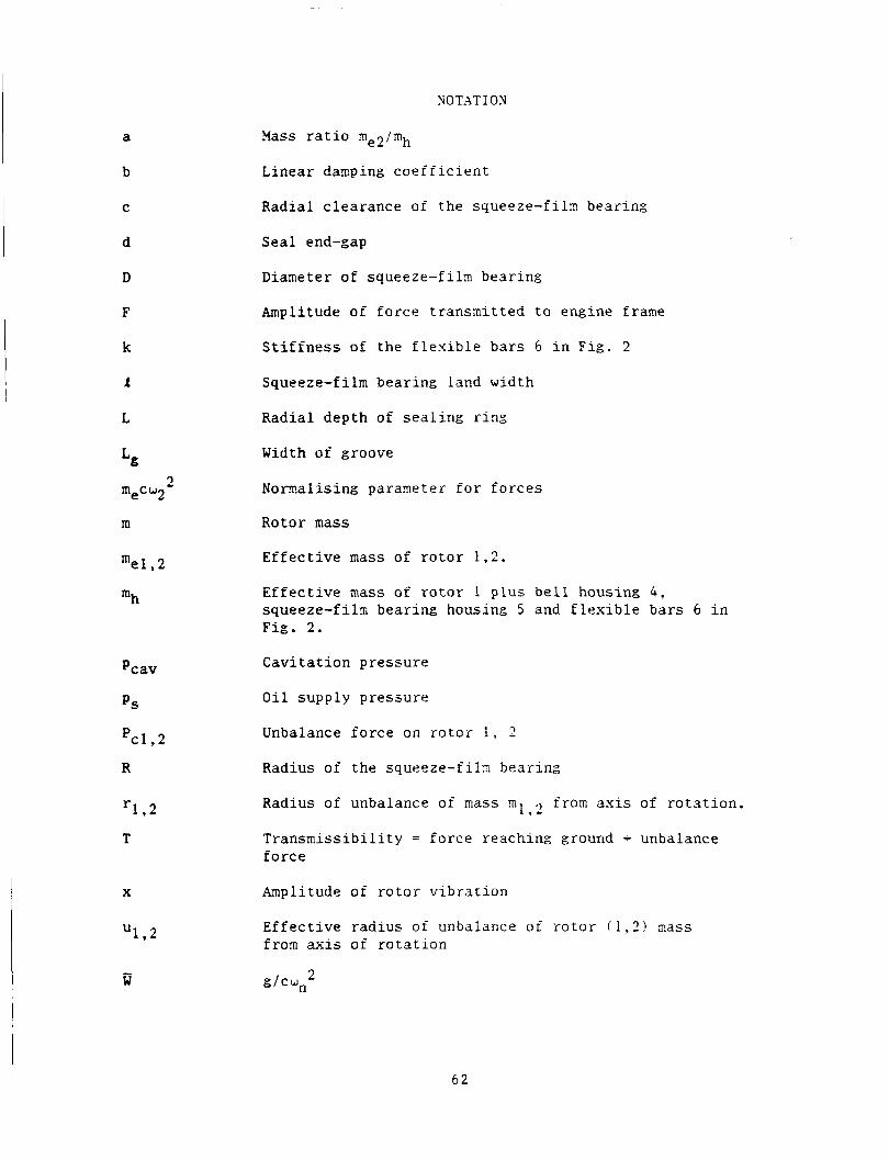
Aero-engine s t r u c t u r e s have very low inhe ren t damping and s o a r t i f i c i a l damping is o f t e n introduced by pumping o i l i n t o annular gaps between t h e cas ings and the o u t e r races of some o r a l l of t he rol l ing-element bear ings suppor t ing the r o t o r s .
The t h i n o i l f i l m s s o formed a r e c a l l e d squeeze f i l m dampers and they can be b e n e f i c i a l i n reducing r o t o r v i b r a t i o n due t o unbalance and keeping t o reasonable l i m i t s t h e f o r c e s t r ansmi t t ed t o t h e engine cas ing . However, squeeze-film dampers a r e no to r ious ly non-linear and as a r e s u l t can in t roduce i n t o t h e assenbly such phenomena as subhamonic o s c i l l a t i o n s , jumps and combi- na t ion f requencies .
The purpose of t h e research descr ibed i n t h i s p a p e r is t o i n v e s t i g a t e such phenomena both t h e o r e t i c a l l y and experimental ly on a t e s t f a c i l i t y reproducing t h e e s s e n t i a l f e a t u r e s of a medium-size aero engine.
The forerunner of t h i s work has been publ ished i n r e f s . [ 1 ] , [ 2 ] . I t was concerned wi th the examination of a squeeze-film damper i n s e r i e s wi th housing f l e x i b i l i t y when suppor t ing a r o t o r . The s t r u c t u r e represented t o a l i m i t e d e x t e n t t h e e s s e n t i a l s of t he pro jec ted R o l l s Royce RB401 engine. That research demonstrated the a b i l i t y t o c a l c u l a t e t he o i l - f i lm f o r c e s a r i s i n g from t h e squeeze f i l m from known motions of the bear ing components and showed t h a t t he dynamics of a s h a f t f i t t e d w i t h a squeeze f i l m bearing can be p red ic t ed rea- sonably accu ra t e ly .
An aero-engine w i l l normally have a t l e a s t two s h a f t s and s o i n a d d i t i o n t o the e x c i t a t i o n f o r c e s which a r e synchronous w i t h t he r o t a t i o n of one s h a f t , t he re w i l l a l s o be f o r c e s a t o t h e r f requencies from o t h e r s h a f t s ope ra t ing on the squeeze-fi lm damper. The present paper is concerned w i t h t h e o r e t i c a l and experimental work t o cons ider severe loading of squeeze-fi lm dampers and t o inc lude these a d d i t i o n a l e f f e c t s . The t h e o r e t i c a l methods a r e similar t o those d iscussed i n re ferences [ l l and 121.
Now wi th General E l e c t r i c Company, C inc inna t i , U . S . A .
61 PRECEDING PAGE BLANK NOT FILMED
https://ntrs.nasa.gov/search.jsp?R=19890013524 2018-07-13T18:58:50+00:00Z
a
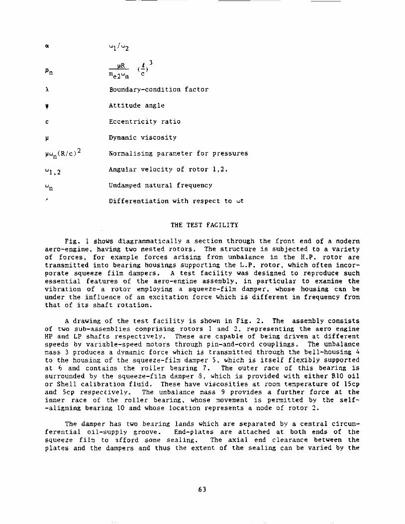
NOTATION
?lass ratio me2imh
b
C
d
D
F
k
L
L
2 mecu2
m
mel , 2
mh
Pcav
PS
PC1.2
R
1 * 2 r
T
X
1 * 2 U
- W
Linear damping coefficient
Radial clearance of the squeeze-fih bearing
Seal end-gap
Diameter of squeeze-film bearing
Amplitude of force transmitted to engine frame
Stiffness of the flexible bars 6 in Fig. 2
Squeeze-film bearing land width
Radial depth of sealing ring
Width of groove
Nomalising paraaeter for forces
Rotor mass
Effective mass of rotor 1.2.
Effective inass of r o t o r 1 p l u s bell housing 4 , squeeze-filn bearing housing 5 and flexible bars 6 in Fig. 2.
Cavitation pressure
Oil supply pressure
Unbalance force on r o t o r 1 , 2
Radius of the squeeze-filx bearing
Radius of unbalance of mass m 1
Transmissibility = force reaching ground - unbalance force
from axis of rotation. .I
Amplitude of rotor vibration
Effective radius of unbalance o f rotor ( 1 , 3 ) xass from axis of rotation
d C y l 2
6 2
or
x
Y
w 1 . 2
Boundary-condition f a c t o r
A t t i t u d e angle
E c c e n t r i c i t y r a t i o
Dynamic v i s c o s i t y
Nomal i s ing pararneter f o r pressures
Angular v e l o c i t y of r o t o r 1 . 2 .
Undamped n a t u r a l frequency
D i f f e r e n t i a t i o n with r e spec t t o w t
THE TEST F A C I L I T Y
F i g . 1 shows diagrammatically a s e c t i o n through t h e f r o n t end of a modern aero-engine, having two nested r o t o r s . The s t r u c t u r e is subjec ted t o a v a r i e t y of f o r c e s , f o r example f o r c e s a r i s i n g from unbalance i n t h e H.P. r o t o r are t r ansmi t t ed i n t o bear ing housings suppor t ing the L.P. r o t o r . which o f t e n incor- po ra t e squeeze f i l m dampers. A t e s t f a c i l i t y was designed t o reproduce such e s s e n t i a l f e a t u r e s of t he aero-engine assembly, i n p a r t i c u l a r t o examine t h e v i b r a t i o n of a r o t o r employing a squeeze-fi lm damper, whose housing can be under the in f luence of an e x c i t a t i o n fo rce which is d i f f e r e n t i n frequency from tha t of i ts s h a f t r o t a t i o n .
A drawing of t h e t e s t f a c i l i t y i s shown i n F i g . 2 . The asseinbly c o n s i s t s of two sub-assemblies comprising r o t o r s I and 2 , r ep resen t ing the ae ro engine trP and LP s h a f t s r e spec t ive ly . These a r e capable of being d r iven a t d i f f e r e n t speeds by var iable-speed motors through pin-and-cord coupl ings. The unbalance sass 3 produces a dynamic fo rce which is t ransmi t ted through the bell-housing 4 t o t he housing of t h e squeeze- f i ix dasper 5 , which is i t s e l f f l e x i b l y supported a t 6 and con ta ins the r o l l e r bear ing 7 . The o u t e r race of t h i s bear ing is surrounded by the squeeze-film damper 3 , which is provided wi th e i t h e r R10 o i l o r S h e l l c a l i b r a t i o n f l u i d . These have v i s c o s i t i e s a t roorn t eape ra tu re of 15cp and 5cp r e spec t ive ly . The unbalance mass 9 provides a f u r t h e r f o r c e a t t h e i n n e r race of t he r o l l e r bear ing, whose rnovement is p e m i t t e d by the s e l f - - a l ign ing bearing 10 and whose loca t ion r ep resen t s a node of r o t o r 1 .
The damper has two bear ing lands which a r e sepa ra t ed b:; a c e n t r a l circum- f e r e n t i a l oi l -supply groove. End-plates a r e a t t ached a t both ends of t h e squeeze f i l a to a f f o r d some s e a l i n g . The ax ia l end c learance between the p l a t e s and the dampers and thus the e x t e n t of t h e s e a l i n g can be va r i ed by the
63
i n s e r t i o n of spacing s h i a s . The r o t a t i o n of t h e damper journa l is prevented by dogs loca ted i n one of the end p l a t e s , providing s u f f i c i e n t c learance t o a l low the jou rna l t o zove i n any pa r t of the squeeze- f i ln c learance space. The squeeze- f i ln damper d i a n e t e r is s e t by the o u t e r race of the r o l l e r bear ing 7 (140 mm!. The damper land length and i t s r a d i a l c learance a r e t y p i c a l of ae ro engine a p p l i c a t i o n ( F i g . 3 ) .
The r i g parameters
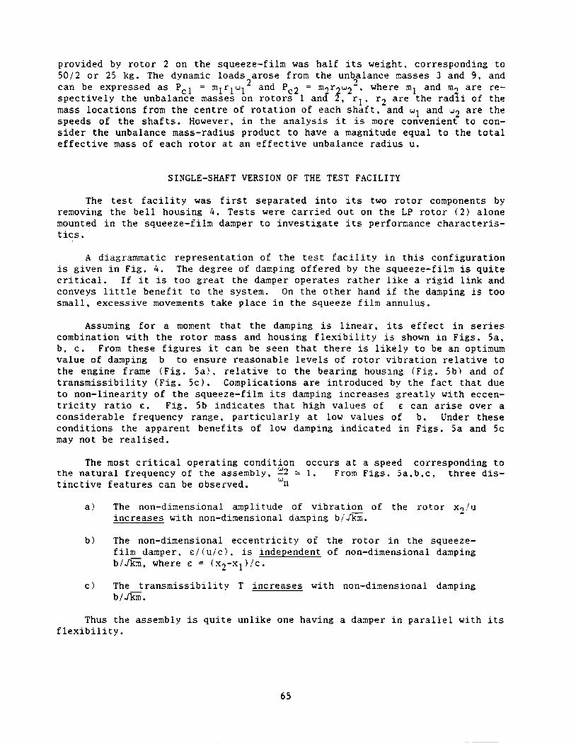
P r e l i a i n a r y i z p u l s e t e s t s were c a r r i e d out t o de f ine the t o t a l e f f e c t i v e s t i f f n e s s of the f l e x i b l e ba r s 5 and t o f i n d the e f f e c t i v e masses of r o t o r s 1 and 2 a t t he squeeze-fi lm loca t ion . From t e s t s on t h e flexibly-mounted housing a lone , i t s na tu ra l frequency was found t o be 192 Hz. Us ing an e f f e c t i v e housing inass of .3 kg the t o t a l s t i f f n e s s of t h e f l e x i b l e bars was found t o be
was 7 5 Hz i n the ho r i zon ta l and 71 Hz i n the v e r t i c a l d i r e c t i o n . The d i f f e r - ence was almost c e r t a i n l y due t o the novenent of bear ing 7 w i th in i ts squeeze f i l m annulus . This was empty of o i l a t the t i n e of t e s t i n g and promoted bounc- ing of bear ing 7 , By taking 73 Hz a s an averaged frequency, t he e f f e c t i v e mass of r o t o r 2 was found t o be 22.16 kg. A similar t e s t was c a r r i e d out wi th r o t o r 1 i n p o s i t i o n and wi th r o t o r 1 rernoved, and f i n a l l y wi th both r o t o r s i n posi- t i o n . Table 1 shows the f ind ings of a l l t h e t e s t s i n a concise fom,.
about 5.68 x 10 2 N / m . With r o t o r 2 a lone i n p o s i t i o n , the na tura l frequency
Table 1
t I I
I Arrangement :Hor i zon ta l : V e r t i c a l I E f f e c t i v e Accepted I (Hz) I ( H z ) mass : Natural :
I I Freq. , I
Squeeze f i l m (SF) housing
only
Rotor 2 and SF assembly
Rotor 1 and SF assembly
Rotors 1 and
, f I I I
I 192 192 I I I I
I
I 75 71 I I
I I
I
I 1 54 103 I
I I I
I I I
21 6 1 . 2 I 43.4 I
3.9
22 .2 ( r o t o r 2
on ly )
10 .o ( r o t o r 1
on ly )
32.4
I I 192 ! , I
I I 73 : I I
, I
1
I 98 , I I
I
, I 62 1 I
I I I
The undamped n a t u r a l frequency of the complete assenbly was taken as 62 Hz (3720 c/min) and i t can be seen t h a t the e f f e c t i v e mass i n the l a s t case is about equal t o the sum of those i n the previous two cases . The s t a t i c l o a d
6 4
provided by r o t o r 2 on the squeeze-fi lm was ha l f its weight, corresponding t o 5 0 / 2 o r 25 kg. The dynamic loads a rose from the unb3alance nasses 3 and 9 , and can be expressed as Pcl = m l r l w 1 2 and Pc2 = m 2 r , w 2 - . where m1 and TI? a r e re- s p e c t i v e l y the unbalance masses on r o t o r s 1 and f, r l , r2 a r e the r a d i i of the mass l o c a t i o n s from t h e c e n t r e of r o t a t i o n of each s h a f t , and w1 and w2 a r e the speeds of t h e s h a f t s . However, i n the a n a l y s i s i t is more convenient t o con- s i d e r t he unbalance mass-radius product t o have a magnitude equal t o the t o t a l e f f e c t i v e mass of each r o t o r a t an e f f e c t i v e unbalance r ad ius u.
SINGLE-SHAFT VERSION OF THE TEST FACILITY
The t e s t f a c i l i t y was f i r s t sepa ra t ed i n t o i t s two r o t o r components by renovirig the b e l l housing 4 . Tes t s were c a r r i e d ou t on the LP r o t o r ( 2 ) a lone mounted i n the squeeze-fi lm damper t o i n v e s t i g a t e i t s perforxance c h a r a c t e r i s - t i c s .
A diagrammatic r ep resen ta t ion of the t e s t f a c i l i t y i n t h i s conf igu ra t ion is g iven i n F i g . 4 . The degree of danping o f f e r e d by the squeeze-film is q u i t e c r i t i c a l . I f i t is too g r e a t t he damper ope ra t e s r a t h e r l i k e a r i g i d l i n k and conveys l i t t l e b e n e f i t t o the sys t en . On the o t h e r hand i f the danping is too s m a l l , excess ive moveaents take p lace i n the squeeze f i l m annulus.
Assuming f o r a moment t h a t t he damping is l i n e a r , i t s e f f e c t i n s e r i e s combination wi th t h e r o t o r mass and housing f l e x i b i l i t y is shown i n F i g s . 5a, b , c . From these f i g u r e s i t can be seen t h a t t h e r e is l i k e l y t o be an optisum va lue of damping b t o ensure reasonable l e v e l s o f r o t o r v i b r a t i o n r e l a t i v e t o the engine frame ( F i g . 5a?. r e l a t i v e t o t h e bear ing housing ( F i g . 5 b ) and of t r a n s m i s s i b i l i t y ( F i g . 5c). Complications a r e in t roduced by t he f a c t t h a t due t o non- l inear i ty of t h e squeeze-film i t s damping i n c r e a s e s g r e a t l y wi th eccen- t r i c i t y r a t i o E . F i g . 5b i n d i c a t e s t h a t high va lues of E can a r i s e over a cons iderable frequency range, p a r t i c u l a r l y at low va lues of b. Under these cond i t ions the apparent b e n e f i t s of low damping ind ica t ed i n F i g s . 5a and 5c may not be r e a l i s e d .
The most c r i t i c a l ope ra t ing cond i t ion occurs a t a speed corresponding t o Fron F i g s . 5 a , b , c , t h r e e dis- the n a t u r a l frequency of t he a s s e m b l y , :2 2 1.
t i n c t i v e f e a t u r e s can be observed. "n
a ? The non-diaensional anp l i tude of v i b r a t i o n of t he r o t o r x2!u i n c r e a s e s wi th non-dinensional danping bid%.
b ? The non-dimensional e c c e n t r i c i t y of t he r o t o r i n the squeeze- f i l m damper, c!(u/c) , is independent of non-dimensional damping b/&, where E = (x , -x l ) / c .
c ) The t r a n s m i s s i b i l i t y T i nc reases w i t h non-dinensional damping b l f i k .
Thus the assembly is q u i t e un l ike one having a damper i n p a r a l l e l with i t s f l e x i b i l i t y .
65
Pre l ix ina ry t e s t s were f i r s t run on the reduced t e s t f a c i l i t y t o a s c e r t a i n whether t hese t r ends were exh ib i t ed i n t h e a c t u a l non-linear system. Various means were adopted by which the e f f e c t i v e daaping could be a l t e r e d . For exaxple , damping could be increased by
i! inc reas ing the o i l v i s c o s i t y ii :) t i gh ten ing the s e a l i n g , o r iii 1 i nc reas ing the s u p p l y pressure .
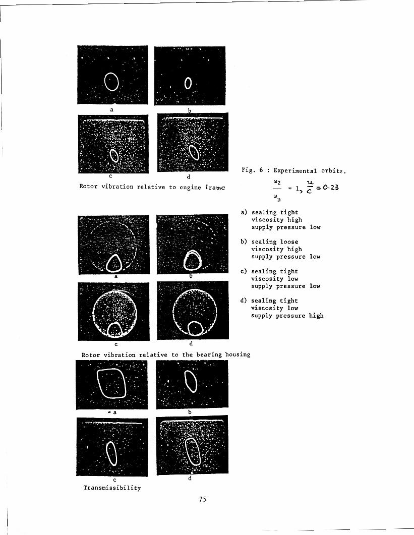
Figs . 6a, b , c show t h e r e s u l t s ob ta ined f o r var ious s e a l i n g cond i t ions , o i l v i s c o s i t i e s and supply pressures . From t h e s e , conclusions can be drawn which a r e c o n s i s t e n t wi th the th ree d i s t i n c t i v e f e a t u r e s us ing t h e l i n e a r damping nodel. This model thus provides a reasonable q u a l i t a t i v e guide t o damper performance i n the most c r i t i c a l reg ion of r o t o r opera t ion .
The next purpose of t he reduced t e s t f a c i l i t y was t o look f o r evidence of j u p phenomena and sub-hamonic v i b r a t i o n s i n the frequency responses as these had been observed i n c e r t a i n engine t e s t s Gihere the o i l v i s c o s i t y was low.
E f f o r t s were the re fo re aade t o produce cond i t ions on the t e s t f a c i l i t y , which were l i k e l y t o be conducive t o such jumps. This indeed proved t o be poss ib l e when the support f l e x i b i l i t y w a s locked out and when t he supply p re s su re t o t h e squeeze-filrr! was a t a f a i r l y low l e v e l . F i g . 7a shows a sequence of o r b i t s of r o t o r v i b r a t i o n r e l a t i v e t o the squeeze- f i ln damper housing us ing a s u p p l y pressure of 5 p s i . A t about 3450 rev/min a pronounced jump up w a s observed. This was a l z o s t c e r t a i n l y due t o a- change i n the e f f e c t i v e parameters governing s y s t e n per foraance . This change was probably brought about by sudden vent ing of the squeeze f i l m c learance space from atmos- phere, r e s u l t i n g i n a change of l e v e l a t which the negat ive hydrodynamic pressure i n the squeeze f i l m was c u r t a i l e d . F i g . 7a shows a s e t of p re s su re record ings which seen to bear t h i s ou t . This would r e s u l t i n much sma l l e r squeeze- f i ln f o r c e s and hence a much l a r g e r o r b i t of v i b r a t i o n of t he r o t o r c e n t r e , and can be p red ic t ed by nuze r i ca l cornputation ( F i g . 7b) . For the l a t t e r purpose, t he hydrodynamic squeeze-fi lm f o r c e s were numerical ly der ived by i n t e g r a t i n g the o i l - f i l n ! pressure around the c i r c m f e r e n c e of t he damper. These f o r c e s depend on the o i l - f i l a c a v i t a t i o n model used and on the end-plate c l ea rance expressed as a X f a c t o r 121 . The \ -€ac to r desc r ibes the boundary cond i t ions ixposed a t the ends of the squeeze- f i ln dazper by the t i g h t n e s s of the end-seals and i n the present research has been extended t o cover var ious a / , r a t i o s (Fig , . 7 c ) . I n the present ca se where the S/, r a t i o is a045 a X-factor of 0.0'3 was used, being appropr i a t e t o an end p l a t e gap/c learance r a t i o of 0 . 2 3 and an end-plate c learance of 0.053 nun. The non-linear equa- t i o n s o f motion were then solved by i n t e g r a t i o n a t each t h e s t e p of a marching scherne.
With regard t o subham.onic v i b r a t i o n s , F i g . Sa shows a success ion or' o r b i t s of the LP s h a f t < 2 ! r e l a t i v e t o the squeeze- f i ln housing f o r a u / c value or' 0 . 3 3 and using S h e l l c a l i b r a t i o n f l u i d as the l u b r i c a n t . The speed range covered was 3830 t o 5075 revlmin. with the undamped n a t u r a l frequency a t 4300 revjni:) ( i 3 Hz). The c e n t r e of the LP r o t o r executed a b u t t e r f l y type of no t ion , such t h a t i t co rq le t ed each "winZ=" f o r a l t e r n a t e r evo lu t ions of the
66
r o t o r . This half-engine o r d e r motion p e r s i s t e d over a wide range of opera- t i o n a l speed. Eventual ly t h e "wings" coa lesced a f t e r the c r i t i c a l speed was passed t o produce an e s s e n t i a l l y s i n g l e o r b i t . The p red ic t ed o r b i t s f o r t he same speeds a r e shown i n F i g . ab , i n which the same double looping is c l e a r l y ev ident . Coalescing i s p red ic t ed somewhat l a t e r i n the speed range than was measured.
Z-YODLLATION
The z-mod technique p resen t s a g r e a t dea l of u se fu l i n f o m a t i o n on the harmonic conten t of a s i g n a l i n a very compact way and by t h i s means i t is poss ib l e t o apprec i a t e an o v e r a l l perforinance s i g n a t u r e of an engine over a wide speed range. A Z-siOd is similar t o a "water fa l l " diagram used i n r o t a t i n g machinery d i a g n o s t i c s except t h a t engine speeds a r e arranged along t h e x a x i s , i n s t e a d of a long the y a x i s , frequency content is d isp layed along t h e y a x i s i n s t e a d of a long the x a x i s and the s t r e n g t h of a frequency component is represented as a co lour ( o r as a degree of b lackness) i n s t e a d of a laid-back peak.
By w a y of e l u c i d a t i n g t h i s technique, cons ide r F i g . 9a which shows an experimental z-mod of ho r i zon ta l components of LP r o t o r v i b r a t i o n r e l a t i v e t o the squeeze-film housing using a spec ia l ly-adapted c o m e r c i a l s p e c t r a l ana lyse r . I t w i l l be observed t h a t h a l f - i n t e g e r o r d e r frequency components manifest theniselves s t r o n g l y around the n a t u r a l frequency of 7 3 Hz.
Software was developed t o o b t a i n t h e o r e t i c a l z-mods wi th the wide range of co lou r s a v a i l a b l e on many microcomputers. This made poss ib l e d i r e c t com- pa r i sons of p r e d i c t i o n s with the experimental z-mods.
The z-mod p r e s e n t a t i o n of nurnerically-predicted h o r i z o n t a l LP s h a f t vibra- t i o n r e l a t i v e t o the squeeze-fi lm damper housing is shown i n F i g . 9b, and coapares wel l wi th the experimental z-mod of F ig . 9a. Half engine o r d e r s a r e indeed p red ic t ed around 73Hz. This is due t o squeeze- f i ln non- l inea r i t i e s mani fes t ing themselves when the o v e r a l l v i b r a t i o n becornes apprec i ab ie , as i t does around t h e n a t u r a l frequency of i3Hz.
Hal f - in teger o r d e r s a r e a comon f e a t u r e i n loose a s s e a b l i e s [ 3 : , I t is not unreasonable t o suppose t h a t i n the present ca se the squeeze- f i ln damper c l ea rance was a c t i n g as a loose assembly on account of t he f a i r l y h igh unbal- ance load toge the r w i t h t he f a i r l y s h o r t squeeze- f i ln damper lands and t h e low v i s c o s i t y of t he o i l supp l i ed . When heavier o i l was introduced a l l ha l f - in t ege r o r d e r harmonics disappeared.
A non-linear systen can be conceived i n which a subharinonic may be e x c i t e d , whose frequency is ha l f t h a t of the e x c i t a t i o n frequency. To show t h a t t h i s is p o s s i b l e , cons ider a systern wi th a square-law r e s t o r i n g f o r c e s u b j e c t t o a s teady fo rce (such as g r a v i t y ) and to harmonic e x c i t a t i o n !such as t h a t due t o unbalance) , both of which a r e provided by the t e s t f a c i l i t y . Let the system s a t i s f y the d i f f e r e n t i a l equat ion ,
mj l + yx + ~2 = P, + p1 cos u t . say
6 7
t h a t i s , the e f f e c t i v e s t i f f n e s s of t he squeeze file is y- s f i u .
Let us assume tha t a poss ib l e s o l u t i o n is
IJ x = A cos - t . 2
cos u t = Po + PI cos u t siA2 nu- ) c o s - * - + - ut
7
Thus A ( y - - 4 2 2 2
This equat ion is s a t i s f i e d f o r
n and w = 2 d 5 - m
The f i r s t two cond i t ions t o r a t t i e s i n c e then the gra
i r r p l y t h a t Po = r i t y f o rce P, i
P which happens t o be conducive U l u s t n e u t r a l i s e d by the dynamic
l i f t - o f f f o r c e P I . This exanple shows t h a t a second harxonic , r e s u l t i n g f r o x the non-linear term. can p r e v a i l , bei:i:: compensated by a c e r t a i n i n t e n s i t y of e x c i t a t i o n a t sone s p e c i f i c frequency. This frequency is i l l u s t r a t e d nos t s t r i k i n g l y when a squeeze-fi lm damper is accompanied by a p a r a l l e l s p r i n g of s t i f f n e s s y . I n t ha t case w corresponds t o twice the f i r s t undamped n a t u r a l frequency and a subhamonic resonance of o r d e r h is exh ib i t ed [ 4 j .
1. ’
Since both harnonics and subhamonics can occur s inu l t aneous ly , o s c i l l a - t i o n s having any ha l f i n t e g e r r a t i o s t o the e x c i t a t i o n frequency a r e p o s s i b l e , g iven the c o r r e c t forin of non l i n e a r i t y . These o s c i l l a t i o n s a r e i n f a c t conbi- na t ion f requencies and w i l l be discussed l a t e r .
THEORETICAL LVALYSIS FOR COMPLETE CONFIGUMTION OF THE TEST FACILITY
The dynamically-equivalent s t r u c t u r e of t h e t e s t f a c i l i t y w i t h both r o t o r s connected is shown i n F i g . 10. I t may be shown 121 t h a t a s e t of non-dimen- s i o n a l parameters which desc r ibe t h i s non-lfnear systern can be? expressed as G, 8,. u1.2’!c, a, a, w2/un. P ~ ~ ~ / ) J L I ~ ( ~ / ~ ~ ~ * , and ps!~tin!Ric!-.
The non-linear equat ions of a o t i o n were so lved by aga in i n t e g r a t i n g a t each t i n e s t e p of a narchin:: s c h w e . To ob ta in a f e e l f o r the kind of r e s u l t s ob ta ined . Fig. l l a shows 3 t yp ica l vibr .2t ion o r b i t f o r the housing of the squeeze-fi lm bear ing r e l a t i v e t o ground while F i g . l l b shows the v i b r a t i o n
68

o r b i t of r o t o r 2 r e l a t i v e t o ground. I n F ig . l l c t h e o r b i t of r o t o r v i b r a t i o n r e l a t i v e t o the squeeze-fi lm housing is shown. For these cases the fol lowing va lues were appl ied :
- No-end s e a l i n g w = 0.23 ar = 2.0
pn = 0.016 a = 1.5
) I W ~ ( R / C ) ~ = 154.5 p s i w 2 j U n = 0.93
Ul/C = 0.23 = -20 p s i Pcav
u2/c = 0 . 2 3 ps = 20 p s i
By p u t t i n g ar = -2.0, counter - ro ta t ion of r o t o r 1 r e l a t i v e t o r o t o r 2 is represented . The r e s u l t i n g o r b i t s f o r > h i s cond i t ion a r e shown i n Fig.12 i n the same sequence as f o r F i g . 11. The same cases were then t r e a t e d wi th end- p l a t e s included (F ig .13) . These las t o r b i t s i n d i c a t e a much nore s t a b l e s y s t e m and s t eady s t a t e s a r e achieved much more qu ick ly , due t o t h e h igher daaping ensured by the end p l a t e s .
COMPARISON OF NUXERICAL ORBITS AXD EXPERIMENTAL OBSERVATIONS FOR COMPLETE COWFIGERATION OF THE TEST FACILITY
Fig.14 shows a specimen s e t of comparisons of r o t o r 2 v i b r a t i o n o r b i t s r e l a t i v e t o the ground, when r o t a t i n g a t 3000 rev/min with r o t o r 1 s t a t i o n a r y . For these comparisons the f u l l non-linear equat ions were solved again us ing t h e X-factor approach developed i n r e f . [21 . Fig. 14 is f o r a case of f a i r l y t i g h t s e a l i n g ( X = 0.03563 and the agreement between experimental and pre- d i c t e d o r b i t s of v i b r a t i o n is seen t o be reasonable , t h e s c a l e f a c t o r s used f o r each s e t of o r b i t s being the same. This agreement is rep resen ta t ive of com- pa r i sons over a wide range of speeds , o i l v i s c o s i t i e s , supply p re s su res and unbalances and a c a v i t a t i o n pressure of -20 p s i has been used throughout.
Consider now c a s e s i n which r o t o r s 1 and 2 r o t a t e i n f irst co- ro ta t ion and then couRter-rotat ion r e l a t i v e t o each o the r . De ta i l ed comparisons between p red ic t ed and expe r inen ta l o r b i t s a r e not appropr i a t e here due t o the indeterin- inacy of the phasing between s h a f t s 1 and 2 a r i s i n g from s l i g h t d r i f t s i n speed. However i t is poss ib l e t o observe c e r t a i n d i s t i n c t i v e f e a t u r e s from comparisons of expe r inen ta l o r b i t s of r o t o r v i b r a t i o n r e l a t i v e t o ground f o r the co- ro ta t ing and counter - ro ta t ing cases . The same d i s t i n c t i v e f e a t u r e s can then be sought i n t h e comparison of t he numerical ly-predicted o r b i t s .
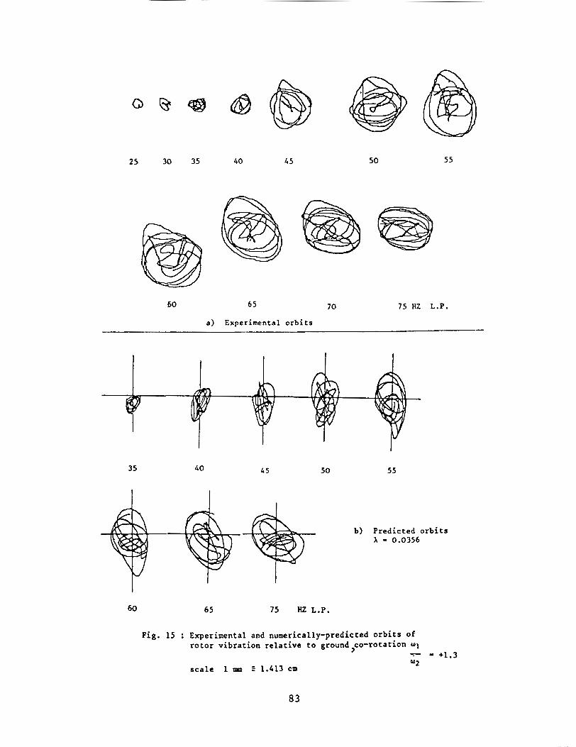
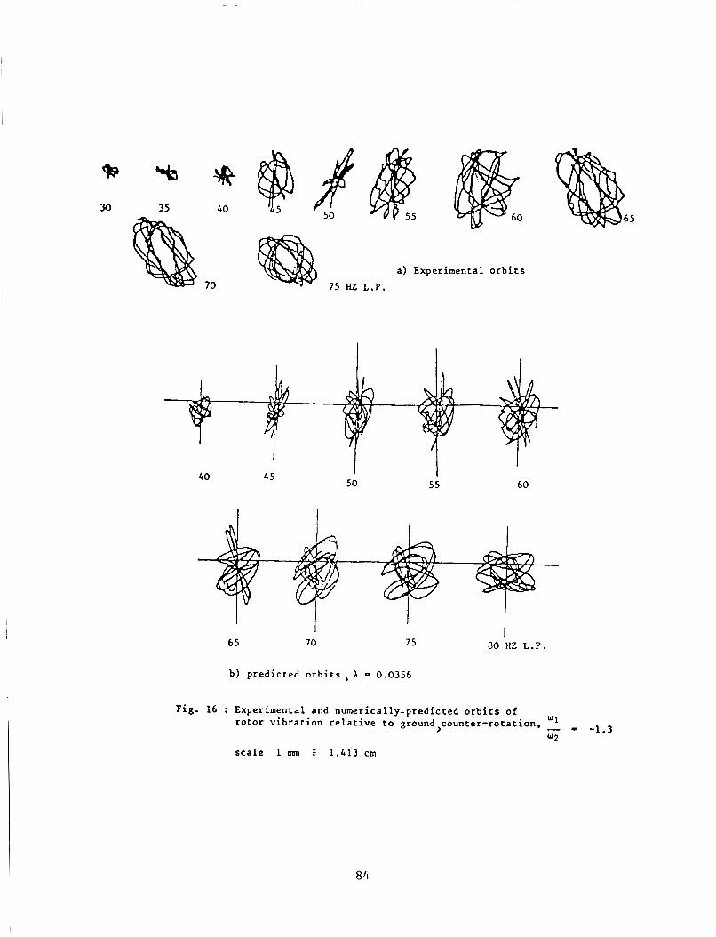
Some experimental o r b i t s a r e shown i n Figs . 15 and 16 (upper ) f o r w1/w2 = 21.3. The xos t d i s t i n c t i v e d i f f e r e n c e s a r e observed t o be the rounded na ture of t he o r b i t s f o r t h e co- ro ta t ing c a s e s as opposed t o the sp iky na tu re f o r t he counter - ro ta t ing . The same f e a t u r e s can be observed i n the numerically-pre- d i c t e d o r b i t s , Fig.15 and 16 ( l o w e r ) . In a d d i t i o n , t h e r e is broad agreement on o r b i t s i z e .
6 9
I t was not iceable dur ing running t h a t the t e s t f a c i l i t y was m c h more noisy f o r counter r o t a t i o n , suggestirig t h a t t r ansmi t t ed f o r c e s were h ighe r , perhaps due t o the more sudden r e v e r s a l s i n t h e o r b i t s .
FREQUENCY CONTENT OF SYSTLY VIBEUTION br3IEN SHAFTS i U E I Y CO-ROTATION AiiD I N COL3TER-ROTATION : COMBINATION FREQUENCIES
I n a l i n e a r s y s t e n resonance occurs uhen t h e systern is e x c i t e d by a har- monic fo rce of frequency near t o t h e undamped n a t u r a l frequency of t he system. I n a non-linear system o t h e r kinds of resonance a r e poss ib l e .
Consider a non-linear system s u b j e c t t o an e x c i t a t i o n c o n s i s t i n g of two harmonic components as we have i n t h i s t e s t f a c i l i t y . Thus.
n.< 7 f(x) = P1 cos (wit O l j 7 P2 cos ! w , t 4 0,) - in whicn we can expand f(x) i n the form or’ a Taylor s e r i e s .
7 f ( x ) = alx + a2x- + a3x3 + ...
x = XI cos W l t - s* cos J2t Now assume t h a t x is roughly harmonic, t h a t is
Thus f(x) w i l l c o n s i s t of t e r n s i n cos w1 ,t
9 -
3 cos- W 1 , 2 t = h ( 1 - cos 2 . J l , , t )
cos W l t c o s u p -- b cos !w1 -I- w 2 ) t .r h cos i d l - W,!t -
A l l poss ib l e l i n e a r combinations of the two f requencies !dl and w2 thus appear and i n gene ra l i t can be s a i d t h a t t he s o l u t i o n w i l l con ta in the f r e - quenc i e s
and nwl f mw2
where in and n a r e whole nunbers . the l a t t e r being known as coxbinat ion o s c i l l a t i o n s . They a l s o manifested t h e m e l v e s i n ha l f - in t ege r o rde r s during t e s t s on the s ing le - sha f t ve r s ion of the t e s t f a c i l i t y ( F i g . 9!.
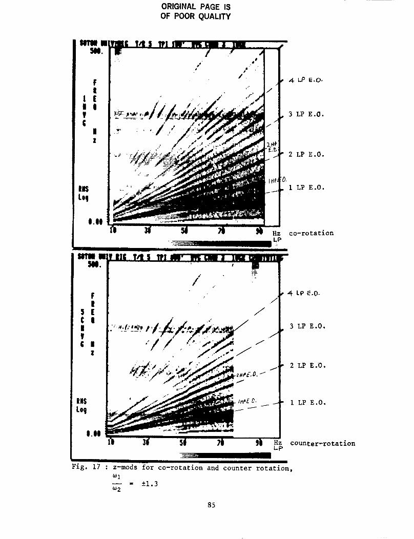
F i g . 17 shows expe r ixen ta l z-cads f o r c a s e s of co- ro ta t ion and counter- r o t a t i o n i n which wliw2 = 51.3. These r e l a t e t o v e r t i c a l v i b r a t i o n or‘ the squeeze-fi lm housing r e l a t i v e t o ground. Yany L? and IiP engine o rde r s a r e
70
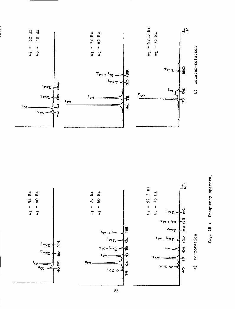
present i n both. as a r e probable combination f requencies . By t ak ing a v e r t i c a l s e c t i o n of the z-mod a t L.P. r o t o r speeds of s a y 4 0 , 60 and 7 5 r e v i s , frequency s p e c t r a can be cons t ruc ted . F i g s . lSa , b show such s p e c t r a f o r co- ro ta t ion and counter - ro ta t ion r e spec t ive ly . Some sugges t ions a r e made on F i g . 13 as t o what t hese f requencies might be i n terms of HP and LP r o t o r speeds.
CONCLCSIONS
The purpose of the research descr ibed i n t h i s paper has been t o reproduce on a t e s t f a c i l i t y phenomena exh ib i t ed i n aero-engine t e s t s . These included subhannonic o s c i l l a t i o n s , jumps i n frequency response and combination frequen- c i e s . A 1 1 of these e f f e c t s were reproduced and could be p red ic t ed by numerical computation o r by apprec i a t ion of non-linear mechanics. Furthernore. a t speeds i n t h e v i c i n i t y of the undanped n a t u r a l frequency, a l i n e a r t r e a t n e n t gave a sound understanding of t r ends i n v i b r a t i o n performance.
A method was presented by which the above f e a t u r e s could be apprec ia ted i n a conprehrnsive w a y . This is known as the z-aodulation technique and u t i l i s e s up-to-date computer graphics f a c i l i t i e s .
R E F E R E X E S
[ l ] Holmes, R . and Dogan. M. ' I n v e s t i g a t i o n of a r o t o r bear ing asse2hly inco rpora t ing a squeeze f i l m damper bear ing . ' Proc. I n s t n . Zech. Engrs. v o l . 2 4 , No. . 3 , 1932.
[ 2 ] Holses , R and Dogan, M . 'The performance of a s e a l e d squeeze-film bearing i n a f l e x i b l e support s t r u c t u r e . ' Proc. In s tn . Mech. Engrs . vo l . 199, No. C1. 1935.
[ 3 ] Angelo, M. 'V ibra t ion Monitoring of Nachines. Bruel nd Kjoer Technical Review 30. 1 1387, pp.5,6.
141 Xikola jsen , J . L . and Holaes. R. ' I n v e s t i g a t i o n of squeeze-film i s o l a t o r for the vibration c o n t r o l of a flexible r o t o r . ' Proc. i n s t n . NYlech. Engrs. v o l . 2 1 . ?io. 4 , 1979.
71
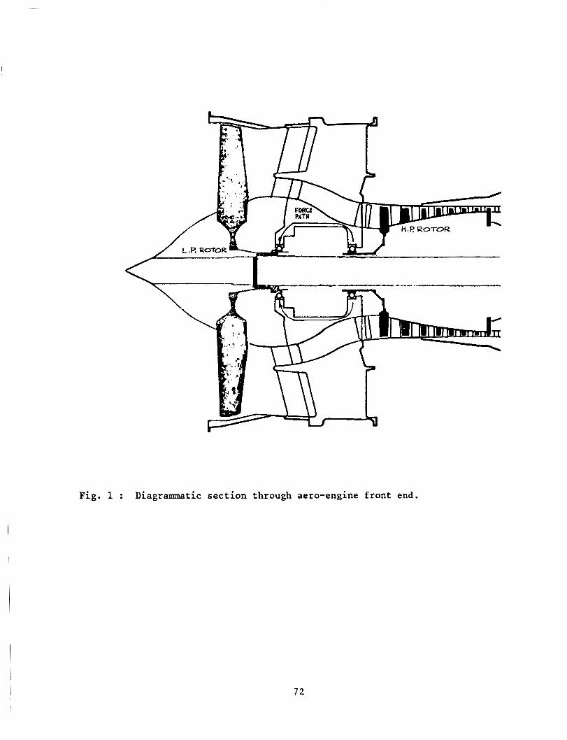
Fig. 1 : Diagrammatic section through aero-engine front end.
72
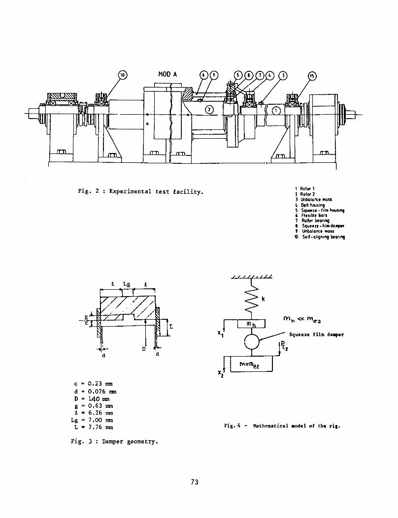
Fig. 2 : Experimental test facility.
9. Lg a
c = 0.23 m d = 0.076 nun D = l 4 O m g = 0.63 m 1 = 6.26 m
Lg - 7.00 mm L = 7.76 mm
1 Rotor 1 2 Rotor2 3 Unbolonce moss L Bell housing 5 Sguccze - fi lm howq 6 flexiblc bors 7 Roller beorinp 0 Squeeze -fi lm domprr 9 Unbalance moss 10 Self -aligning korinp
Fig. 4 - Mathematical model of the r ig .
Fig. 3 : Damper geometry.
73
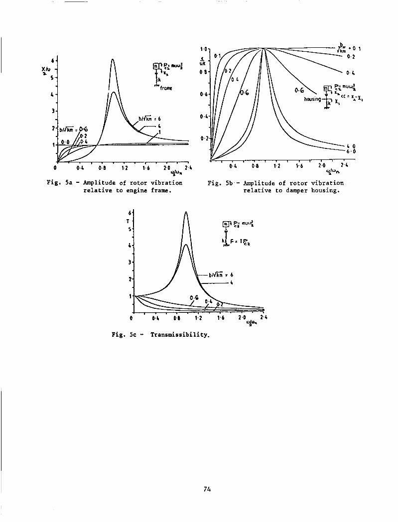
Fig. 5a - Amplitude of rotor vibration relative to engine frame.
1 . 1 . 1 1 I ~ ' '
0.2 0.8 1.2 1.6 2.0 2.4 O h ,
relative to damper housing.
a
Fig. 5b.- Amplitude of rotor vibration
Fig. 5c - Transmissibility.
74
a
Rotor vibration relative to engine frame
C
w2 u - = F=0*23 w n
d
Rotor vibration relative to the bearing housing.
b
C
Transmissibility d
75
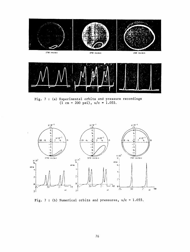
Fig. 7 : (a) Experimental orbi ts and pressure recordings (1 cm = 200 p s i ) , u/c = 1.055.
Fig. 7 : (b) Numerical orbits and pressures, u/c = 1.055.
76
I \
End-pl at e gap/clearance, d/c 1
elea E n d
e a k 0104
a 9 e 0102
h
e a 0 8 . End-plate gap/clearance ,& 1
Fig. 7c - X values for different a,, ratios.
77
~~
3880 revlmin 5075 revlrnin
a) Experimentally-observed orbits
3880 revjmin 4059 rev/min
b) Numerically-predicted orbits
Fig. 8 : Subharmonic vibratiom.
Q 5075 revhin
a) experimental b) numerically predicted
642
zm
iEO
a
I E,O.
3 1.0,
2 1.0.
I E.O.
8 1.0. 1 4 . 6 73 z 1 6 1 ~ ~
Rotor speed, t+a
Fig. 9 : z-modulations of horizontal LP rotor vibration relative to the squeeze-film housing.
78
2 unb a1 anc e
J
L Q Mkf damper
unbalance I
Fig. 10 - Line diagram of test rig.
7 9
0 I
3
U 3
!?
. -
S
n 0 Y
a
n (I "
A
v (I
80
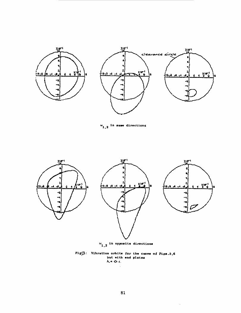
w in name d i r e c t i o n s 1.2
w i n Opposite d i r e c t i o n s 1 . 2
F i g p : Vibration orbit. f o r the cmes of P i g 8 . 5 , 6 but with end plate . A= 0 . 1 .
81
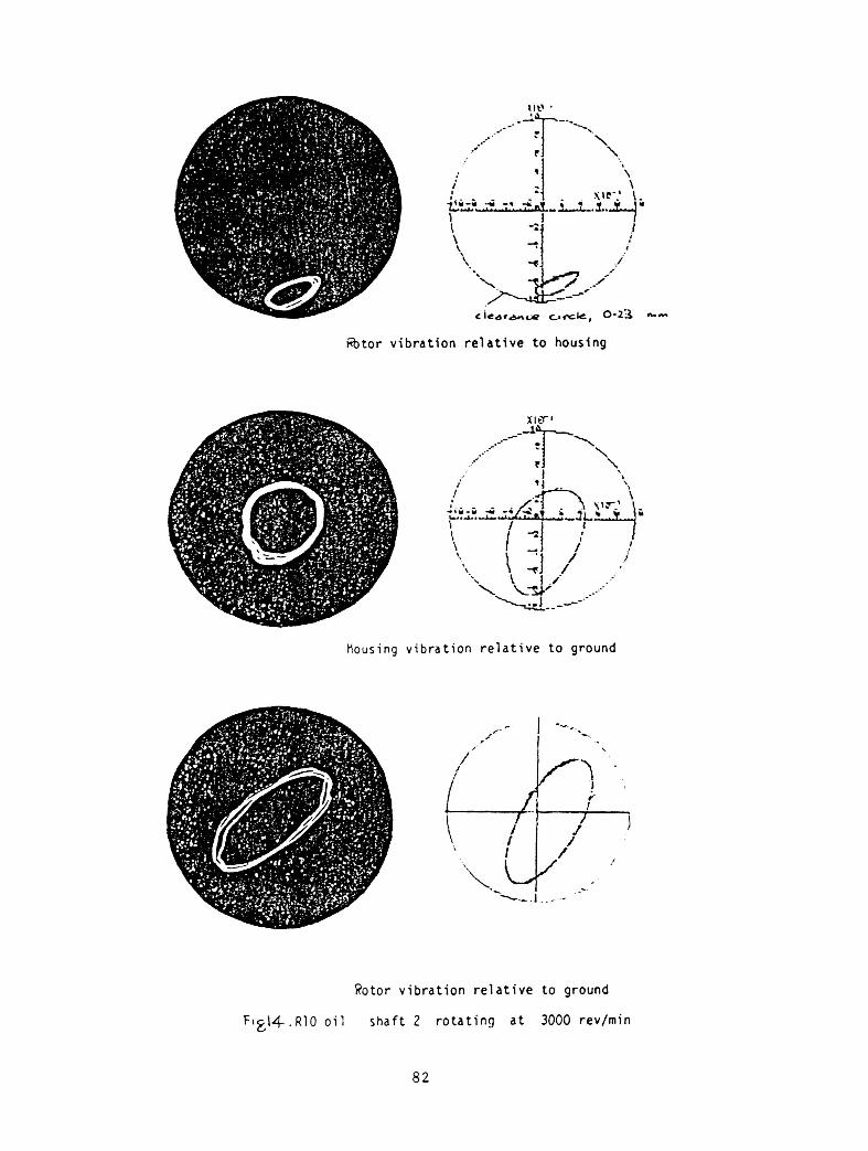
&tor v i b r a t i o n r e l a t i v e t o housfng
nousing v i b r a t i o n r e l a t i v e t o ground
Rotor v i b r a t i o n r e l a t i v e t o ground
F i g \ 4 . R l O o i l s h a f t 2 r o t a t i n g a t 3000 rev/min
a2
0
25
B
30 35 40 45 50 55
60 65 70 75 HZ L . P .
a) Experimental orbits -
35 40 4 5 50 55
b) Predicted orbits X - 0.0356
6 0 65 75 HZ L.P.
Fig. 15 : Experimental and numerically-predicted orbits of rotor vibration relative to ground > co-rotation ~1
- - +1.3 W 2
scale 1 IIQ I 1.413 cm
83
5 30 35 40 50
a) Experimental orbits
70 75 Hz L . P .
40 45 I 1 50 55 60
1
65 70 75 80 HZ L . P .
b) predicted orbits , A = 0.0356
Fig. 16 : Experimental and numerically-predicted orbits of rotor vibration relative to ground counter-rotation, 2 I
scale 1 nun f 1.413 cm
-1.3 > w 2
8 4
ORIGINAL PAGE IS OF POOR QUALITY
m a m.
F t
1 E I @ t C I 2
tlcs 109
0.04
___ LP - __
m a m.
F t
s t C I I v C I
2
R l S 109
0.04
r Fig. 17 : z-mods for co-rotation and counter rotation,
i ...
_- e F .-
,/
/
' 4 Lp E.O.
, 3 LP E.O.
' 2 LP E.O.
3. , 1 LP E.O.
co-rotation
I
4 LP E.0-
3 LP E.0.
2 LP E.0 .
1 LP E.O.
counter-rotation
2 2 N O m e
u II
4 t Y 3 3
N N x x N O m u II II I
N N x x a 0 - \ D
u u
4 t Y 3 3
N m x 2
N L X d
g .I4 & a & 0 k I k al &
0 U
n P
a &I u 0 al a u)
k Frc
.. co rl
a & 0 k I 0 0
n a
86
Recommended