ROWSE HYDRAULIC RAKES COMPANY, INC.84504 State Hwy 11, Burwell, Nebraska 68823
Phone: 308-348-2276Fax: 308-348-2059
Toll-Free: 800-652-1912E-mail: [email protected]
Website: www.rowserakes.com
OPERATOR’S MANUAL AND PARTS LISTIncluding Assembly and Operating Instructions and Parts List
THE SIDEKICKWINDROW TURNER

Revised May 2016
LIPS Printing Service · Kearney, NE
SERIAL NO. ________________________ PURCHASE DATE: _____________________
ROWSE HYDRAULIC RAKES CO., INC84504 State Hwy 11, Burwell, Nebraska 68823
Phone: 308-348-2276 Fax: 308-348-2059Toll-Free: 800-652-1912
E-mail: [email protected]
Website: www.rowserakes.com
CONTENTS SUMMARY
SECTION
A Introduction A
B Assembly Instructions B
C Operating Instructions C
D Service D
E Troubleshooting E
F Parts List F

TABLE OF CONTENTS
SECTION A: INTRODUCTION To The Owner 1
General Outline of This Manual 1
Safety & Special Information 2
Limited Warranty 2
Warranty Details 3
Bolt Torque Information 4
Tire Inflation Pressures 4
SECTION B: ASSEMBLY INSTRUCTIONS Windrow Turner Models Discussed 5
Serial Number 5-6
Assembly, Terminology, Terms & Phrases 7
SECTION C: OPERATING INSTRUCTIONS Introduction 8
Operating Safety 8
Important 8
Hydraulic Requirements 9
Adjusting Wheel Weight & Height 9
SECTION D: SERVICE Safety Reminders 10
Lubrication 11-20
SECTION E: TROUBLESHOOTING Introduction 21
Service Safety 21
Service Checklist 21
Troubleshooting Guide 22
Symptom 22
Not Raking Clean 22
Excessive Breakage of Teeth 22
Windrow is Not Positioned
Upside Down When Turned 22
Raking Wheels Will Not Go Down 23
Castor Wheels Shimmy (Wobble) 23
Raking Wheels Won’t Go Down on
New Rake 23
Hydraulic Functions Don’t Work 23
SECTION F: PARTS LIST Windrow Turner Overall View 26-27
Tongue Assembly 28-29
Frame Assembly 30-31
Lift Rod Stabilizer Roller Assembly &
Compression Spring Assembly With Limiter 32-33
Hub, Wheel and Tire Assembly 34-35
Raking Wheel & Raking Arm Assembly 36-37
Hydraulics 38-39
WT-Lift Cylinder 40
1
SECTION A:INTRODUCTION
To The Owner General Outline Of This ManualCongratulations on your selection of the Rowse
Windrow Turner to aid you in your haying operation. This operator’s manual will assist you in realizing the benefits you can gain from using the Rowse Windrow Turner.
The Rowse Windrow Turner has been designed, manufactured, and tested to make you another satisfied Rowse customer.
You will find it very beneficial to read this entire manual to have a thorough understanding of the Windrow Turner before taking it to the field. Also, keep this manual handy for future reference. Become familiar with the adjustments required to obtain maximum, trouble-free, efficiency and performance.
Proper operation and care of the Windrow Turner contribute immensely to its successful performance. A properly lubricated, adjusted and cared for implement saves downtime, labor costs, fuel, and repairs.
Haying conditions will vary from year to year. Items affecting conditions include amount of moisture, kind of crop, etc. Therefore, the normal settings outlined in this manual are really suggested starter settings. Adjustment may need to be made to fit a particular raking situation. Operation information contained in this manual will aid in making the necessary adjustments. Consult your Rowse Dealer concerning unusual field conditions or special applications.
Your Rowse Dealer will be glad to answer any questions you may have on the operation and care of this product. Also, for parts and service, see your Rowse Dealer. Always use genuine Rowse parts to ensure proper fit and optimum performance.
Information in this manual is arranged under six main section headings.
Following the introduction, the steps for assembly of the basic unit and optional equipment are discussed. Then, important points in operating the Windrow Turner and optional equipment are covered.
Safety, service, and the troubleshooting guide give additional operating information.
A parts list is also included in this manual. An index in the back of the manual aids in finding information on a specific item.
A
CAUTIONRead the Operator’s Manual.Learn to operate this machine SAFELY.Be alert. Observe ALL Safety Practices.Machines can be hazardous in the hands ofan UNFAMILIAR, UNTRAINED orCOMPLACENT operator.Don’t risk INJURY or DEATH.
!

2A
New Rowse Agricultural and Industrial Machines Rowse Hydraulic Rakes Co., Inc., (hereinafter “Rowse”).
Warrants each new agricultural and indus trial machine or equipment, (hereinafter “Product”) to be free from defects in materials and workmanship under normal use for which it was intended for a pe riod of one year from the date of purchase. The obli gation of Rowse under this warranty is limited to re pairing or at its option, replacing F.O.B. factory any part or parts which is reported in writing to Rowse within 30 days from the date of failure thereof and specifying the nature of the defect or failure and which Rowse inspections shall disclose to have been defec tive. It is the responsibility of buyer to transport at his own expense the product to the dealers service shop or Rowse factory. When requested by Rowse, part or parts shall be returned for inspection, transpor tation prepaid, to Rowse or a place designated by Rowse. In no event shall Rowse be obligated for inci-dental or consequential damages caused by such fail ure or defect, including, but not limited to, the loss of crops, inconvenience, rental of replacement equip ment, loss of profits, or other commercial loss.
There is no warranty with respect to used products or new products that have been improperly assembled by one other than an authorized dealer, modified or altered, repaired, neglected, or used for purposes other than those for which it was intended.
EXCEPT AS SPECIFICALLY WARRANTED HEREIN, ROWSE DISCLAIMS ANY OTHER WARRANTY OF MERCHANTABILITY, IMPLIED OR EXPRESSED, AND FITNESS FOR PURPOSE. THERE ARE NO WARRANTIES WHICH EXTEND BEYOND THAT FACE HEREOF.
Limited Warranty
Safety and Special InformationSafety Information
1. Throughout this manual and on machine decals im-portant safety information appears with:
a) The Safety-Alert Symbol: b) And one of the three signal words: CAUTION, WARNING, or DANGER
2. Use of these three signal words is limited to safety messages only.
3. The definition of each of these signal words follows:
CAUTIONIndicates a potentially hazardous situation which, if not avoided, may result in minor or moderate injury. It may also be used to alert against unsafe practices.
WARNINGIndicates a potentially hazardous situation which, if not avoided, could result in death or serious injury, and includes hazards that are exposed when guards are removed. It may also be used to alert against unsafe practices.
DANGERIndicates an imminently hazardous situation which, it not avoided, will result in death or serious injury. This signal word is to be limited to the most extreme situations, typically for machine components which, for functional purposes, cannot be guarded.
!
!
!
! !
4. For additional safety information, refer to Section D: Safety.
Special InformationMessages that pertain to operational instructions,
maintenance messages, lubrication instructions, etc., use signal words such as: Note, Notice, Important, or Attention. The signal word is set off in bold and all caps as shown in the example below:NOTE: Indicates a special point of information.

3
Warranty DetailIntroduction
The following information explains for you the details of ROWSE’s farm equipment warranty. These details include an explanation of the criteria for determining warrant, those items which are included for warranty, those which are not cov ered, and information about how to obtain war ranty service.
Warranty Determination Only defective parts are covered under this warranty.
Any part found to be defective in accor dance with the provisions of this warranty will be repaired or replaced by an authorized ROWSE dealer.
Items Covered by Warranty ROWSE’s warranty includes the replacement or
repair of any part or parts of machines or attach-ments on ROWSE new equipment purchased from an authorized ROWSE dealer (except tires and tubes) which are defective in material, workman ship, or both.
Obtaining Warranty Service To obtain warranty service, contact the author ized
ROWSE dealer from whom the machine was purchased. In the event this is not practical to do, any authorized ROWSE dealer may perform war ranty work. However, a servicing dealer who did not sell the unit has the right to charge the cus tomer the difference between their normal shop rate and the rate Rowse allows for warranty work.
Items Not Covered 1. Tires shall be warranted by the sell ing dealer or by
local representatives of the tire manufacturer of said product.
2. Dealer Travel Time—The customer shall be responsible for payment of dealer travel time to the machine or to deliver the machine to the dealer’s service shop for repair. ROWSE war ranty does not cover travel time.
3. Used Equipment —ROWSE warrant shall apply only to original owner of new equipment sold by an authorized ROWSE dealer. ROWSE shall have no liability for used equipment.
4. No warranty shall be made on any equipment or parts that have been modified, or altered in any way without prior approval and knowledge of ROWSE, nor is there warranty if service, other than normal replacement of service items, is performed by someone other than an authorized ROWSE dealer.
5. Normal Wear or Maintenance Parts—ROWSE shall not be responsible for normal replacement parts such as cutting knives, chains, belts, filters, oil, rake teeth, nor for parts which are worn out unless they are deemed to be defective in material or workmanship.
6. No warranty shall apply to damage resulting from accident, misapplication, abuse, or damage caused by environment; (such as exposure to corrosive material).
Leased or Rented Units If a unit is leased or rented, the warranty period
starts on the date the unit is first leased and/or rented. If the unit is sold to a second user at a later date, it is then considered a used machine.
Improvements ROWSE continually strives to improve its
products and, therefore, reserves the right to make improvements or changes without incurring any obligations to make such changes or additions on equipment previously sold.
NOTICECharges for pick up and/or delivery and service calls
are not covered by warranty.
A

4A
1/4” 6 10 14 5/16” 12 19 27 3/8” 23 35 50 7/16” 35 55 80 1/2” 55 85 120 9/16” 75 130 175 5/8” 105 170 240 3/4” 185 300 425 7/8” 175 445 685 1” 270 675 1,030 1 1/8” 375 910 1,460 1 1/4” 530 1,250 2,060
Bolt Torque Information1. Tighten bolts to torques shown in the chart unless
otherwise specified.
2. Bolts having locknuts with cadmium or wax finish should be tightened to approximatley 50% of amounts shown on charts.
3. Locknuts should be Grade C.
4. Over tightening bolts can cause as much damage as under tightening. Tightening a bolt beyond the recommended range can reduce its shock load capacity.
5. Check and retighten all bolts, nuts, and set screws: a) After initial 10 hours of use, b) And again after every 50 hours of use.
TIRE INFLATION PRESSURES1. Proper tire inflation is important for safe and efficient
operation of the Windrow Turner.2. The recommended tire inflation pressure is 25 PSI.
Figure A-7: Bolt Grade Designation
SAE-2 SAE-5 SAE-8
Figure A-8: Bolt Torque Information
A = Bolt Diameter
BoltDiameter
BOLT TORQUE in Ft-Lbs SAE 2 SAE 5 SAE 8
Figure A-9: Recommended Torque for Hub Bolts and Nuts.
NOTE: Do NOT overtorque. Retorque after one hour.
Thread Recommended Size Torque (Ft-Lbs)
1/2-20 UNF 80 - 90
9/16-18 UNF 110 - 120
5/8-18 UNF 125 - 135
3/4-16 UNF 275 - 285

5
Windrow Turner Model DiscussedAll information in this manual pertains to the
Windrow Turner. Figure B-1 lists the Models covered in this manual.
Figure B-1: Model Numbers and Descriptions
Model Model Number Description
WT5 5 Wheel Rake
Model Number and Serial Numberof Your Rowse Windrow Turner
For future reference, record below the model number and serial number of your Rowse Windrow Turner.
This information is stamped into the frame on the top of the left front wing of your Windrow Turner. See Figure B-2.
Model Number: _________________________
Serial Number: __________________________
A

6
Seri
al N
umbe
r and
Mod
el N
umbe
r(s
tam
ped
into
the
fram
e)
A
WIN
DRO
W T
URN
ERFI
GU
RE B
-2
7 B
SECTION B:ASSEMBLY TERMINOLOGY, TERMS AND PHRASES
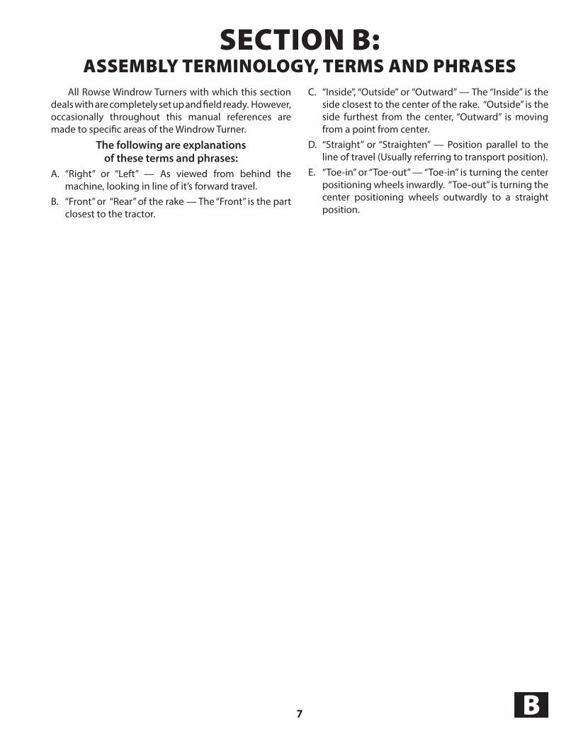
All Rowse Windrow Turners with which this section deals with are completely set up and field ready. However, occasionally throughout this manual references are made to specific areas of the Windrow Turner.
The following are explanationsof these terms and phrases:
A. “Right” or “Left” — As viewed from behind the machine, looking in line of it’s forward travel.
B. “Front” or “Rear” of the rake — The “Front” is the part closest to the tractor.
C. “Inside”, “Outside” or “Outward” — The “Inside” is the side closest to the center of the rake. “Outside” is the side furthest from the center, “Outward” is moving from a point from center.
D. “Straight” or “Straighten” — Position parallel to the line of travel (Usually referring to transport position).
E. “Toe-in” or “Toe-out” — “Toe-in” is turning the center positioning wheels inwardly. “Toe-out” is turning the center positioning wheels outwardly to a straight position.

8C
SECTION C:OPERATING INSTRUCTIONS
Introduction1. This section deals with the operating instructions of
the Windrow Turner. For assembly instructions, refer to Section B.
2. Occasionally, reference is made to certain areas of the Windrow Turner. Here are explanations of these phrases.
a) “Right” and “Left” — as viewed from behind the machine.
b) “Front” or “Rear” of the Rake — the “front” is the part closest to the tractor.
c) “Inside” or “Outside” — The “inside” is the side closest to the center of the machine; “outside” is the side away from the center of the machine.
3. Check and retighten all bolts, nuts, and set screws: a) After initial 10 hours of use, b) And again after every 50 hours of use. c) Refer to the Bolt Torque Chart in Section A.
Operating SafetyObserve these instructions for your safety and for
the safe operation of the equipment.
DANGERDo not ride or work on
equipment when it it is moving,or is in a raised position.
! !
WARNINGBe aware of and stay clear of
pinch points that existaround the equipment.
!
CAUTION1. When hitching the Windrow Turner to the tractor,
do not allow anyone to get between the tractor and the Rake.
2. Operate at a safe speed. a) Reduce speed when transporting over rough ground.
3. Be sure to always use the SMV (Slow Moving Vehicle) reflector when using public roads.
!
IMPORTANT:
1. Review the Operator’s Manual and all safety items before working with, maintaining, or operating the Windrow Turner.
9 C
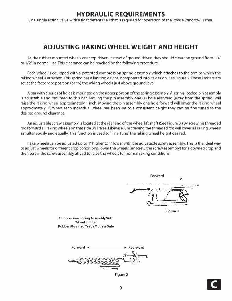
HYDRAULIC REQUIREMENTS One single acting valve with a float detent is all that is required for operation of the Rowse Windrow Turner.
ADJUSTING RAKING WHEEL WEIGHT AND HEIGHT
As the rubber mounted wheels are crop driven instead of ground driven they should clear the ground from 1/4” to 1/2” in normal use. This clearance can be reached by the following procedure.
Each wheel is equipped with a patented compression spring assembly which attaches to the arm to which the raking wheel is attached. This spring has a limiting device incorporated into its design. See Figure 2. These limiters are set at the factory to position (carry) the raking wheels just above ground level.
A bar with a series of holes is mounted on the upper portion of the spring assembly. A spring-loaded pin assembly is adjustable and mounted to this bar. Moving the pin assembly one (1) hole rearward (away from the spring) will raise the raking wheel approximately 1 inch. Moving the pin assembly one hole for ward will lower the raking wheel approximately 1”. When each individual wheel has been set to a consist ent height they can be fine tuned to the desired ground clearance.
An adjustable screw assembly is located at the rear end of the wheel lift shaft (See Figure 3.) By screwing threaded rod forward all raking wheels on that side will raise. Likewise, unscrewing the threaded rod will lower all raking wheels simultaneously and equally. This function is used to “Fine Tune” the raking wheel height desired.
Rake wheels can be adjusted up to 1” higher to 1” lower with the adjustable screw assembly. This is the ideal way to adjust wheels for different crop conditions, lower the wheels (unscrew the screw assembly) for a downed crop and then screw the screw assembly ahead to raise the wheels for normal raking conditions.
Forward
Forward Rearward
Figure 2
Compression Spring Assembly WithWheel Limiter
Rubber Mounted Teeth Models Only
Figure 3

10D
SECTION D:SERVICE
Safety Reminders
DANGER1. Do not ride or work on equipment
when it it is moving, or is in a raised position.
2. Be aware of and stay clear of pinch points that exist around the machine.
! !
WARNING1. High Pressure Fluid Hazard — To
prevent serious injury or death from high-pressure fluid:a) Relieve pressure on system before
repairing, adjusting, or disconnecting.b) Wear proper hand and eye protection
when searching for leaks. Use wood or cardboard instead of hands.
c) Keep all components in good repair.
!
CAUTION1. When lubricating or working on the Windrow
Turner make sure it is resting on the ground. If it is in a raised position, the Windrow Turner should have proper supports to prevent the machine from falling.
2. When lubricating and working around the Windrow Turner be careful not to get cut on any other sharp edges.
!
Tighten Bolts1. Check and retighten all bolts, nuts, and set screws: a) After initial 10 hours of use. b) And again after every 50 hours of use. c) Refer to Bolt Torque Chart in Section A.

11 D
Lubrication, Introduction1. Use a good grade of multi-purpose grease.
2. Make sure all grease fittings are free of dirt and paint before using.
3. Usually, one to two pumps per zerk is sufficient.
4. Lubricate at the end of the season to keep moisture out of critical areas.
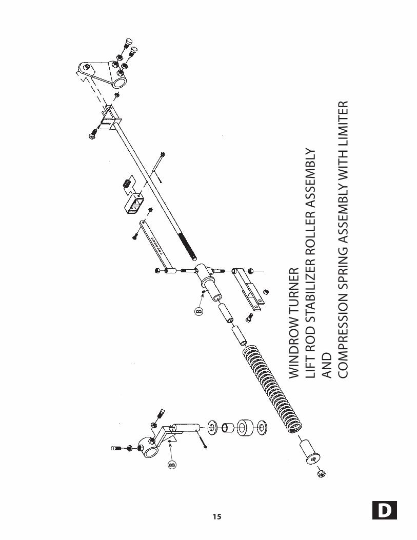
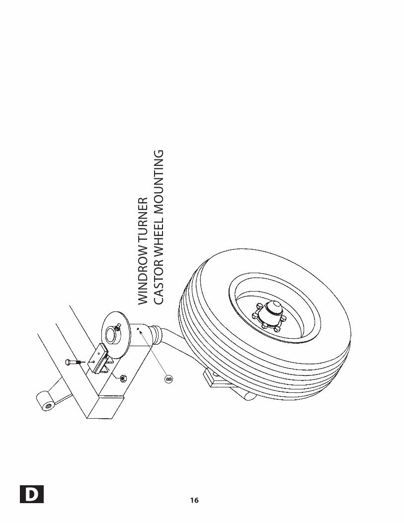
5. Figure D-1 shows an overall view of the Windrow Turner lubrication areas. Subsequent figures give
close-ups of the key areas; signified by the letter B.

12D
Figu
re D
-1
B
B
B
B
BB
B BB
WIN
DRO
W T
URN
ERFI
GU
RE D
-1

13 D
B
B
WIN
DRO
W T
URN
ER T
ON
GU
E

14D
B
B
B
WIN
DRO
W T
URN
ER
MA
IN F
RAM
E
15 D
B
B
WIN
DRO
W T
URN
ER
LIFT
RO
D S
TABI
LIZE
R RO
LLER
ASS
EMBL
YA
ND
COM
PRES
SIO
N S
PRIN
G A
SSEM
BLY
WIT
H L
IMIT
ER
16D
B
WIN
DRO
W T
URN
ERCA
STO
R W
HEE
L M
OU
NTI
NG

17 D
B
WIN
DRO
W T
URN
ERH
UB,
WH
EEL
AN
D T
IRE
ASS
EMBL
Y

18D
B
B
WIN
DRO
W T
URN
ERRA
KIN
G W
HEE
L PA
RTS

19 D
B
WIN
DRO
W T
URN
ER
LUBR
ICAT
ION
OF
THE
RAKI
NG
WH
EEL

20D
B
B
WINDROW TURNERHUB, WHEEL AND TIRE ASSEMBLY

21 E
SECTION E:TROUBLESHOOTING
Introduction
DANGERDo not ride or work on
equipment when it it is moving,or is in a raised position.
! !
CAUTION
Always be aware of other people andyour surroundings so no damage or
injuries occur when operatingthe Windrow Turner.
!
With proper care and maintenance, the Rowse Windrow Turner will give many years of reliable service. When the situation arises where the Windrow Turner performance is not satisfactory, this section on troubleshoot ing will give some pointers in finding and correcting the problem.
This section is divided into two major areas. First, the Service Checklist gives a list of items to check first when diagnosing a problem.
Second, the Troubleshooting Guide gives a list of specific problem symptoms and for each list of pos sible causes and probable remedies.
If after reviewing this section, you are unable to determine and correct the trouble, consult your Rowse Dealer.
Service Safety
Observe these safety instructions for your safety and for the safe operation of the equipment.
WARNING1. High Pressure Fluid Hazard — To
prevent serious injury or death from high-pressure fluid:a) Relieve pressure on system before
repairing, adjusting, or disconnecting.b) Wear proper hand and eye protection
when searching for leaks. Use wood or cardboard instead of hands.
c) Keep all components in good repair.
!
Service ChecklistWhen the Windrow Turner is not performing
satisfactorily, here are some preliminary checks that may help in diagnosing the problem.
Check all hydraulic hoses and fittings, repair or replace as needed.

22E
TROUBLESHOOTING GUIDE Introduction
This troubleshooting guide gives a list of specific problem symptoms and for each a list of possible causes and probable remedies.
Each individual symptom description is shown in larger, italic letters with a black bar above and below the statement. The statement of the symptom looks like this:
Symptom
The possible causes are listed below the symptom statement with a number before each of the possible causes. The possible causes are listed like this:
1. Possible cause. The probable remedy for the cause is listed below the cause with letter of the alphabet before each step of the
remedy. The probable remedy is listed like this: a) Probable remedy.
If after reviewing this section, you are unable to determine and correct the trouble, consult your Rowse Dealer.
Not raking clean
1. Improper height on the raking wheels. a) Adjust the height of wheels off ground. b) Refer to “Adjusting Raking Wheel Weight”.
2. Raking wheels are bouncing. a) Adjust the weight b) Refer to “Adjusting Raking Wheel Weight”.
3. Raking wheels raising off the ground. a) Tractor hydraulics not in float position. b) Refer to “Hydraulic Operating Notes” and “Important - Tractor Hydraulic System”.
4. Hay crop is too green/wet. a) Let the hay crop dry longer.
Excessive breakage of teeth
1. Wheels are too low and are being ground driven and/or not raising the raking wheels in turns. If wheels are being run ground driven (wheels turn because they are contacting the ground). An addit ional compression spring needs to be added to each Compression Spring Assembly to reduce the normal 40# of weight per wheel down to 20-25# per wheel. Failure to do so will result in excessive tooth breaking and/or wheel damage.
a) Refer to the “Operating Notes”.
2. Running too much weight on the raking wheels. a) Refer to “Adjusting Raking Wheel Weight”.
Windrow is Not Positioned Upside Down When Turned
1. Positioning of windrow is determined by ground speed a) More speed turns windrow further over
b) Slower speed reduces the amount the windrow turns c) Raise or remove rear raking wheel

23 E
TROUBLESHOOTING GUIDE (continued)
Raking wheels will not go down
1. On some tractors with closed-center hydraulic systems, hydraulic pressure will not allow kicker wheels to go down. a) Contact Rowse or your Rowse Dealer on how to adjust the tractor valve bank. b) Lubricate “Lift Tube Slide”. c) Lubricate Compression Spring slide.
Castor wheels shimmy (wobble)
1. Wheel dampener is too loose. a) Tighten the front bolt on the dampener clamp on the disc on top of the castor wheel assembly. See Figure F-1. b) If shimmy continues, tighten the set screw attaching the disc to the axle. Make sure the bolt is in the counter sunk portion of the axle.
Raking wheels won’t go down on new rake
1. Transport pins have not been removed. a) With hydraulics connected, raise wheels to up position, remove transport pins on front lift tube.
2. Hydraulic problem. a) See “Raking wheels will not go down” earlier in this section.
Hydraulic functions don’t work
1. Low tractor oil supply. a) Add adequate oil.
2. Hydraulic hoses are not “hooked” in parallel with tractor outlets. a) Switch hoses into correct hydraulic banks.
3. Hydraulics will go only one direction. a) One hose has come loose from tractor inlet. b) Operator is moving tractor lever too far and it is going into float position. c) Wire has come loose on valve solenoid.
NOTE: For factory service assistance call “Rowse Service Department” at (877) 336-3255.
Set Screw
Tighten front bolt on dampener to eliminate wobble
Figure F-1: Dampener on Castor Wheel
Dampener

24E

25
SECTION F:PARTS LIST
IntroductionThis section lists the parts for the Windrow Turner.
It gives the order number, description, and quantity needed.
F

26F
SWL
158
DTS
F50
00#
- WT
1003
BA
LL
- WT
1002
CLE
VIS
WT
5004
WT
5006
WT
5002
WT
5003
WT
5005
WT
5001
WIN
DRO
W T
URN
ERO
VERA
LL V
IEW
8
6
5
9
3
1 2
7
4

27 F
Windrow Turner PARTS LISTTONGUE
Ref. Part No. Description Qty.
1 WT1002 Clevis Hitch (not shown) 1 2 WT1003 Ball Hitch 1 3 SWL158DTSF Jack 1 4 WT5001 Main Frame 1 5 WT5002 Front Frame Extension 1 6 WT5003 Left, Front Wheel Mount 1 7 WT5004 Tongue 1 8 WT5005 Lift Tube 1 9 WT5006 Pin, Tongue Mount 1

28F
1
3
4
5
67
8
67
9
10W
IND
ROW
TU
RNER
TON
GU
E13
12
11
29 F
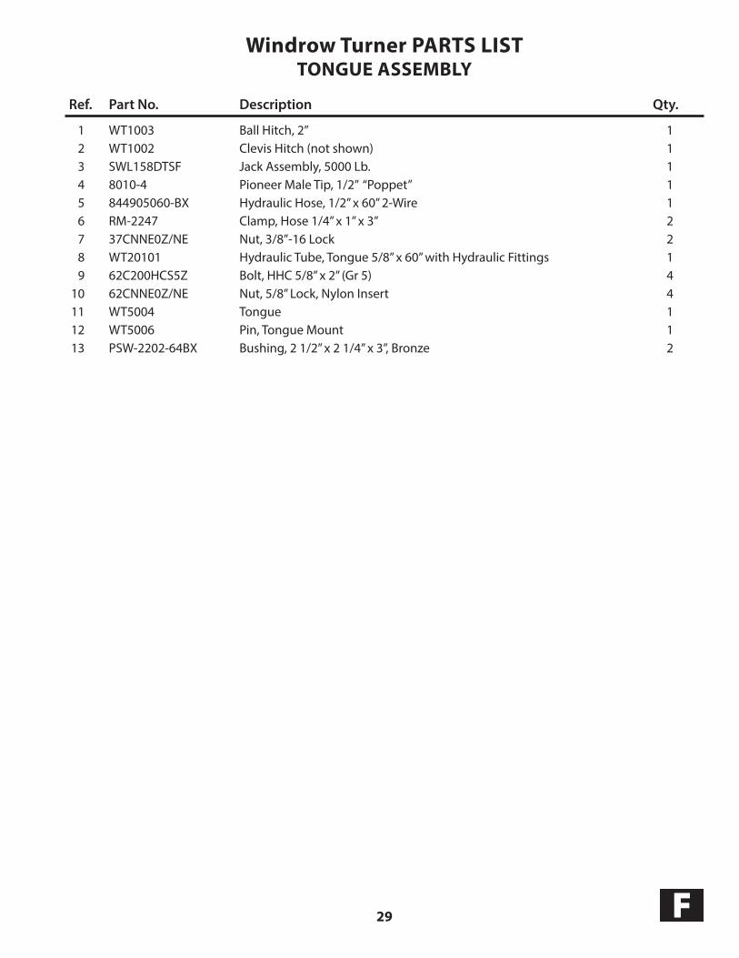
Windrow Turner PARTS LISTTONGUE ASSEMBLY
Ref. Part No. Description Qty.
1 WT1003 Ball Hitch, 2” 1 2 WT1002 Clevis Hitch (not shown) 1 3 SWL158DTSF Jack Assembly, 5000 Lb. 1 4 8010-4 Pioneer Male Tip, 1/2” “Poppet” 1 5 844905060-BX Hydraulic Hose, 1/2” x 60” 2-Wire 1 6 RM-2247 Clamp, Hose 1/4” x 1” x 3” 2 7 37CNNE0Z/NE Nut, 3/8”-16 Lock 2 8 WT20101 Hydraulic Tube, Tongue 5/8” x 60” with Hydraulic Fittings 1 9 62C200HCS5Z Bolt, HHC 5/8” x 2” (Gr 5) 4 10 62CNNE0Z/NE Nut, 5/8” Lock, Nylon Insert 4 11 WT5004 Tongue 1 12 WT5006 Pin, Tongue Mount 1 13 PSW-2202-64BX Bushing, 2 1/2” x 2 1/4” x 3”, Bronze 2
30F
1
9
2
3
4
5
6
78
12
14
13
11
10
15
WIN
DRO
W T
URN
ERRE
AR
FRA
ME

31 F
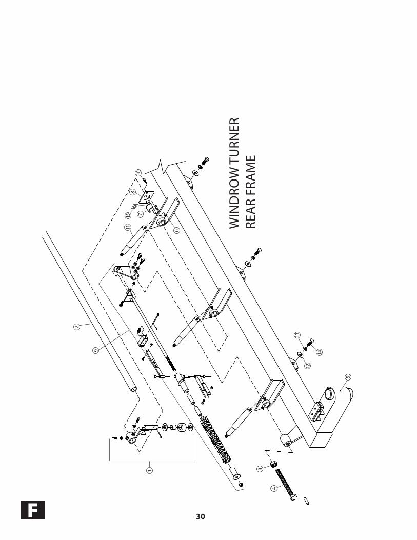
Windrow Turner PARTS LISTMAIN FRAME ASSEMBLY
Ref. Part No. Description Qty.
1 WR5208 RMT Stabilizer, Lift Rod Roller Assembly 1 2 WT5005 138” Lift Rod 1 3 100CNFJ0Z Nut, 1” - 8, Hex Jam 1 4 ULT4165 Lift Rod End Adjuster 1 5 107-100 Zerk, 1/4”-28 St Lub 1 6 37CNNE0Z/NE Nut, 3/8”-16 Lock 1 7 WR78060 Bushing, Lift Rod 1 8 WR1507 RMT Rod Guide Retainer Plate 1 9 WR4925 RMT Compression Spring Assembly 1 10 37C125HCS5Z Bolt, 3/8” - 16” x 1 1/4” G5 2 11 WR150130 Spindle, 1 1/2” x 11 1/2” RMT, Tapped 5 12 62NUSS0Z Washer, 5/8” U55 Flat 5 13 62NLOC0Z Washer, 5/8” Lock 5 pt 5 14 62C200HCS5Z Bolt, 5/8” - 11 - 2” Grd 5 5 15 ULT3013 Spacer, Lift Rod Retainer RMT 1 16 WR4625 Poly Dampener, 1/4” x 5” x 2”, Set of 2 1 17 WR4626 Top Plate, Dampener 1 18 37C225HCS5Z Bolt, 3/8”-16 x 2-1/4” G5 1 19 37CNNE0Z/NE Nut, 3/8”-16 Lock 1 20 WR1030 Dampener, Wheel Lock w/ poly assembly 1

32F
29
28 27
1627
28
25
23
626
22
21
2018
19
18
16
1715
147
5
3
2
4
6 8 9 7
12
11
13
1
10
24
WIN
DRO
W T
URN
ERLI
FT R
OD
STA
BILI
ZER
ROLL
ER A
SSEM
BLY
AN
DCO
MPR
ESSI
ON
SPR
ING
ASS
EMBL
Y W
ITH
LIM
ITER
5
33 F
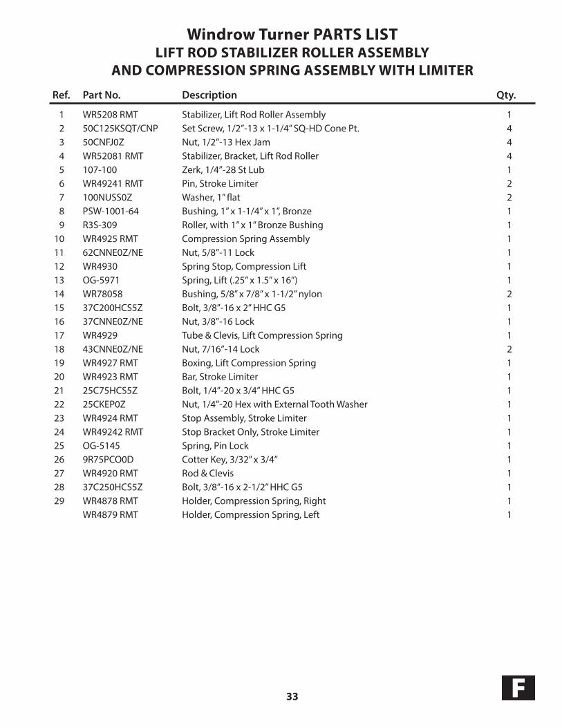
Windrow Turner PARTS LISTLIFT ROD STABILIZER ROLLER ASSEMBLY
AND COMPRESSION SPRING ASSEMBLY WITH LIMITER
Ref. Part No. Description Qty.
1 WR5208 RMT Stabilizer, Lift Rod Roller Assembly 1 2 50C125KSQT/CNP Set Screw, 1/2”-13 x 1-1/4” SQ-HD Cone Pt. 4 3 50CNFJ0Z Nut, 1/2”-13 Hex Jam 4 4 WR52081 RMT Stabilizer, Bracket, Lift Rod Roller 4 5 107-100 Zerk, 1/4”-28 St Lub 1 6 WR49241 RMT Pin, Stroke Limiter 2 7 100NUSS0Z Washer, 1” flat 2 8 PSW-1001-64 Bushing, 1” x 1-1/4” x 1”, Bronze 1 9 R3S-309 Roller, with 1” x 1” Bronze Bushing 1 10 WR4925 RMT Compression Spring Assembly 1 11 62CNNE0Z/NE Nut, 5/8”-11 Lock 1 12 WR4930 Spring Stop, Compression Lift 1 13 OG-5971 Spring, Lift (.25” x 1.5” x 16”) 1 14 WR78058 Bushing, 5/8” x 7/8” x 1-1/2” nylon 2 15 37C200HCS5Z Bolt, 3/8”-16 x 2” HHC G5 1 16 37CNNE0Z/NE Nut, 3/8”-16 Lock 1 17 WR4929 Tube & Clevis, Lift Compression Spring 1 18 43CNNE0Z/NE Nut, 7/16”-14 Lock 2 19 WR4927 RMT Boxing, Lift Compression Spring 1 20 WR4923 RMT Bar, Stroke Limiter 1 21 25C75HCS5Z Bolt, 1/4”-20 x 3/4” HHC G5 1 22 25CKEP0Z Nut, 1/4”-20 Hex with External Tooth Washer 1 23 WR4924 RMT Stop Assembly, Stroke Limiter 1 24 WR49242 RMT Stop Bracket Only, Stroke Limiter 1 25 OG-5145 Spring, Pin Lock 1 26 9R75PCO0D Cotter Key, 3/32” x 3/4” 1 27 WR4920 RMT Rod & Clevis 1 28 37C250HCS5Z Bolt, 3/8”-16 x 2-1/2” HHC G5 1 29 WR4878 RMT Holder, Compression Spring, Right 1 WR4879 RMT Holder, Compression Spring, Left 1

34F
1
2
34 5
6
78
910
12
11
13
14
15
16
17
18
19
2120
2223
24
WINDROW TURNERHUB WHEEL AND TIRE ASSEMBLY
18
17
16
19
20
This is brake that clamps onbrake 24 to eliminate wheel shimmy.

35 F
Windrow Turner PARTS LISTHUB, WHEEL AND TIRE ASSEMBLY
Ref. Part No. Description Qty.
1 75C300HCS5Z Bolt, 3/4” x 3” HHC Grd 5 Per Raking Wheel 2 2 CR16289 Seal, 888 hub 1 3 JL69349 Cone, Inner, 888 hub 1 4 JL69310 Cup, Inner, 888 hub 1 5 107-100 Zerk, 1/4” - 28 St Lub 1 6 W 888 Hub Only, 6 bolt 1 7 LM67010 Cup, Outer, 888 hub 1 8 LM67048 Cone, Outer, 888 hub 1 9 9136831 Washer, 888 hub 1 10 87FNST0Z Nut, slotted 888 hub 1 11 15R125PCO0Z Cotter Key, 5/32” x 1-1/4” 1 12 909905 Cap, Dust, 888 hub 1 13 845502225 Tire, ST225/75R15, 4 ply Radial 1 14 0613945 Bolt, 1/2” x 1-1/4” lug, 888 hub 6 15 0411141 Rim, 15 x 6 x 6 bolt 1 16 12420187 Spindle & Plate, 2” x 7” W888, 6 bolt 1 17 75NLOC0Z Washer, 3/4” lock SPT 2 18 75CNFH5Z Nut, 3/4” - 10 G5 2 19 14344451 Axle, Castor 1 20 107-100 Zerk, 1/4” - 28 St Lub 1 21 PSW-2202-64BX Bushing, 2-1/2” x 2-1/4” x 3”, Bronze 2 22 50C125KSQT/CNP Set Screw, 1/2” - 13 x 1-1/4” SQ-HD Cone Pt. 1 23 50CNFJ0Z Nut, 1/2”-13 Hex Jam 1 24 WR6053 Brake, Disc with bolt & nut, Axle Wheel, 8” 1

36F
1516
1713
1716
1820
1921
21
20
1918
1617
1716
15
11
108
1
9
8
234
53
4
7
6
WIN
DRO
W T
URN
ERRA
KIN
G W
HEE
L PA
RTS

37 F
Windrow Turner PARTS LISTRAKING WHEEL & RAKING ARM ASSEMBLY
Ref. Part No. Description Qty. Per Wheel Assembly
1 WR5900 Wheel, Bare, 19 Tooth 1 WR7900 Wheel, Bare, 24 Tooth 1 2 WR5901 Tooth, Double, 19 Tooth 19 WR5904 Tooth, Double, 24 Tooth 24 3 37NUSS0Z Washer, 3/8” Flat 8 4 37C100HCS5Z Bolt, 3/8”-16 x 1” HHC G5 27 5 WR5905 Poly Plate 1 6 WR6023 Poly Kit w/Fasteners 7 WR6051L Wheel Assembly, LEFT 1 WR6051R Wheel Assembly, RIGHT 1 WR7051L 24 Tooth Wheel Assembly, LEFT 1 WR7051R 24 Tooth Wheel Assembly, RIGHT 1 8 37CNNE0Z/NE Nut, 3/8” Lock 27 9 43C125HCS5Z Bolt, 7/16”-14 x 1-1/4” HHC G5 6 10 43CNNE0Z/NE Nut, 7/16”-14 Lock 6 11 WR6022 Spindle and Plate 1 12 13 WR4928RMT Arm with Boxings, Lift Compression Spring 1 14 WR150130 Spindle, 1-1/2” x 11-1/2” - Tapped 1 15 15234VB Seal, Rake Wheel 2 16 LM67048 Cone, Tapered Roller Bearing 4 17 LM67010 Cup, Tapered Roller 4 18 9136831 Washer, W888 2 19 15R125PCO0Z Cotter Key, 5/32” x 1-1/4” 2 20 9129521 Nut, Slotted 2 21 001601 Cap, Grease 2

38F
1
23
4
WIN
DRO
W T
URN
ERH
YDRA
ULI
C
8
76
9 5
14

39 F
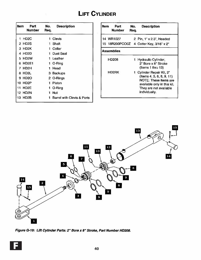
Windrow Turner PARTS LISTHYDRAULICS
Ref. Part No. Description Qty. Per Wheel Assembly
1 HD208 Cylinder, 2” x 8” 1 2 844905108-BX Hydraulic Hose, 1/2” x 108” 2-wire 1 3 PM-BHF-3 Cap, Vent, 1/2” Cylinder Breather 1 4 WR1027 Pin, 1” x 2-3/8” Headed 1 5 18R200PC00Z Cotter Key, 3/16” x 2” 1 6 WT20101 Hydraulic Tube, Tongue, 5/8” x 60” with Hydraulic Fittings 1 7 844905060-BX Hydraulic Hose, 1/2” x 60”, 2 wire 1 8 8010-4 Pioneer Male Tip, 1/2 Poppet 1 9 100N150AMB0/10G Washer, 1 x 1 1/2 x 10 Ga AR 100N150AMB0/14G Washer, 1 x 1 1/2 x 14 Ga AR
AR=As Required
40F

41

42
HYDRAULIC RAKES COMPANY, INC.
BURWELL, NEBRASKA84504 STATE HWY 11OFFICE 308-348-2276
TOLL FREE 800-652-1912
www.rowserakes.com
Recommended