V.A. Orlando
The Mode S Beacon Radar System
Air traffic controllers rely on primary and secondary radars to locate and identifYaircraft. Secondary, or beacon, radars require aircraft to carry devices called transponders that enhance surveillance echoes and provide data links. Airports currently use asecondary-radar system known as the Air Traffic Control Radar Beacon System(ATCRBS). However, ATCRBS has limitations in dense-traffic conditions, and thesystem's air-to-ground data link is limited. In response to these shortcomings, LincolnLaboratory has developed the Mode Select Beacon System (referred to as Mode S), a nextgeneration system that extensive laboratory and field testing has validated. In additionto significant surveillance improvements, Mode S provides the general-purpose groundair-ground data link necessary to support the future automation of air traffic control(ATC). The Federal Aviation Administration (FAA) is currently installing the system withinitial operation scheduled for 1991.
Airports around the world currently use atype of secondary radar known in the UnitedStates as the Air Traffic Control Radar BeaconSystem (ATCRBS) [11. Because this radar system was developed more than 30 years ago, it isbeginning to strain under today's increasedlevels of air traffic.To replace ATCRBS, LincolnLaboratory has developed the Mode Select Beacon System (referred to as Mode S) [21, which isscheduled for initial operation at U.S. airports in1991.
Mode S (a combined beacon radar andground-air-ground data-link system) is designed for the dense traffic environments expected in the future. To supP9rt the automation
(' ... 1 J
ofair traffic control (ATC),Mode S boasts two at-tributes: accurate surveillance even in densetraffic conditions. and reliable ground-airground communications capability.
Because Mode S is capable ofcommon-channel interoperation with ATCRBS, the fonner canbe installed over an extended transition perioddUring which Mode-S systems will eventuallyreplace ATCRBS ones. In fact, a major designreqUirement in developing Mode S was to ensurethat the system could be implemented in anevolutionary manner. By the time Mode-S deployment begins in 1991. about 200.000 aircraft and 500 ground-based radars will be using
'l11e Lincoln Laboratory Journal, Volume 2, Number 3 (1989)
ATCRBS. Mode S is designed to operate in thisATCRBS environment in a way that wouldpermit a gradual transition to all-Mode-Soperation.
Providing a high degree of compatibility between Mode S and ATCRBS has achieved thecapabilityfor such a transition. Mode S uses thesame interrogation and reply frequencies asATCRBS, and the signal formats have been chosen to pennit substantial commonality in hardware. Such compatibility will permit a smooth,economic transition inwhich Mode-S radars willprovide surveillance of ATCRBS-equipped air
craft and Mode-S transponders will reply toATCRBS radars.
This article begins with a description ofATCRBS. followed by a discourse on thesystem's limitations in regions of high trafficand sensor densities. Next, details of Mode Sare presented with an emphasis on the improvements provided by the monopulse direction-finding techniques and the specific features provided by Mode-S surveillance andthe Mode-S integral data link. A description follows of the field measurements thatwere made to validate the Mode-S design. Finally, this article comments on the currentstatus of Mode-S implementation in the UnitedStates.
345
Orlando - The Mode S Beacon Radar System
Air Traffic Control Radar BeaconSystem
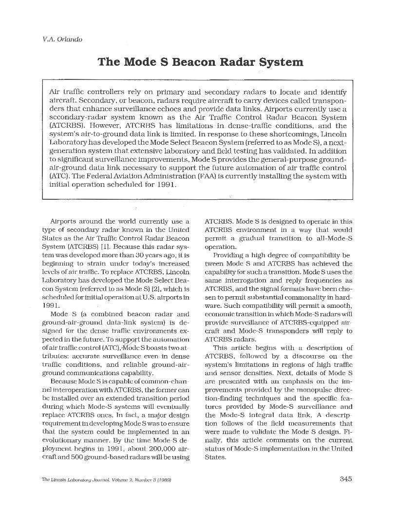
Figure 1 schematically illustrates the operation of the current ATCRBS. The ATCRBS antenna, which is typically mounted above theprimary-radar antenna, has a fan-beam patternwith a horizontal beam width of 2° to 3°. Thescan rate is 4.8 s for a sensor used at an airportterminal, and 10 s to 12 s elsewhere. CivilATCRBS transponders accept two types ofinterrogations. Mode A has an 8-f.Js p)-to-P3 spacingand elicits a 20.3-f.Js reply that contains one of4,096 pilot-entered identity codes. Mode C hasa 21-,us p)-to-P
3spacing and elicits a similar
reply that contains the aircraft's barometricaltitude referenced to standard atmosphericconditions. The purpose of the Pz pulse isdescribed in the following section.
ATCRBS Transmit SidelobeSuppression
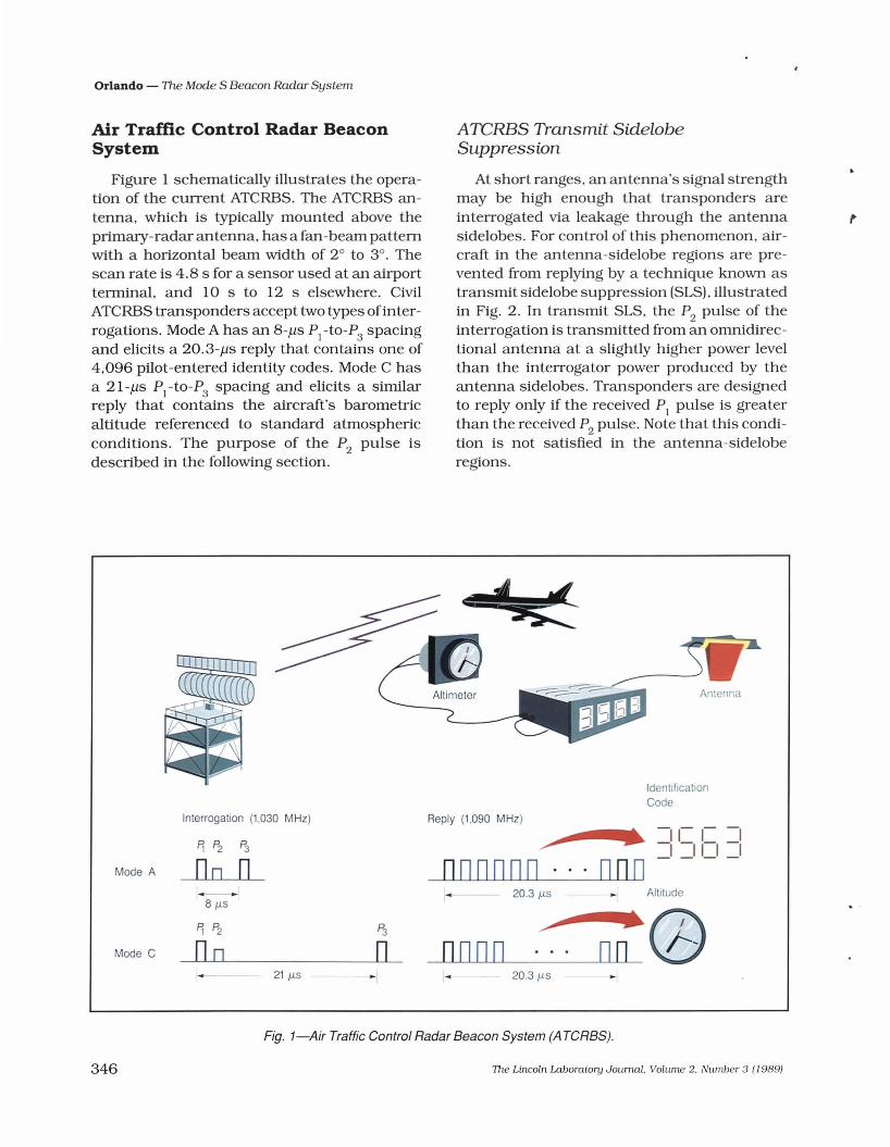
At short ranges, an antenna's signal strengthmay be high enough that transponders areinterrogated via leakage through the antennasidelobes. For control of this phenomenon, aircraft in the antenna-sidelobe regions are prevented from replying by a technique known astransmit sidelobe suppression (SLSJ, illustratedin Fig. 2. In transmit SLS, the Pz pulse of theinterrogation is transmitted from an omnidirectional antenna at a slightly higher power levelthan the interrogator power produced by theantenna sidelobes. Transponders are designedto reply only if the received PI pulse is greaterthan the received Pz pulse. Note that this condition is not satisfied in the antenna-sideloberegions.
Fig. 1-Air Traffic Control Radar Beacon System (A TCRBS).
::a..
An cnna
346 7he Lincoln Laboratory Journal. Volume 2. Number 3 (19891
,
/ Omnidirectional Antenna Pattern P2
Directional Antenna Pattern(P1, P3)
Fig. 2-Sidelobe-suppression (SLS) operation.
ATCRBS Limitations
The current ATCRBS satisfies operationalrequirements in most airspace. The system,however, has the following limitations in regionsof high traffic and sensor densities.(1) Synchronous garbling (described later).(2) Azimuth inaccuracy (described later).(3) Fruit. Replies received from interroga
tions by neighboring sensors are calledfruit. These unwanted replies are notsynchronized with the local sensor'sinterrogations, and are thus received atrandom times. The presence offruit caninterfere with the reception of a wantedreply. As a result, high fruit rates canproduce a detectable decrease in performance. The use of high pulse-repetition frequencies (PRF) for slidingwindow detection contributes to thisproblem. (Sliding-window detection willbe discussed in a following section.)
(4) Overinterrogation. In a region containingmany sensors, a transponder will receivea high rate of interrogations and SLSs.Consequently, the transponder may beunable to reply when it receives an interrogation from the local sensor. As is thecase with fruit, the use of high PRFsaggravates overinterrogation.
(5) Aircraft identification. In many regions ofthe world, the limit of 4,096 differentMode-A codes is insufficient.
The Lincoln Laboratory Journal. Volume 2. Number 3 (1989)
Orlando - The Mode S Beacon Radar System
Synchronous Garbling ofATCRBS Replies
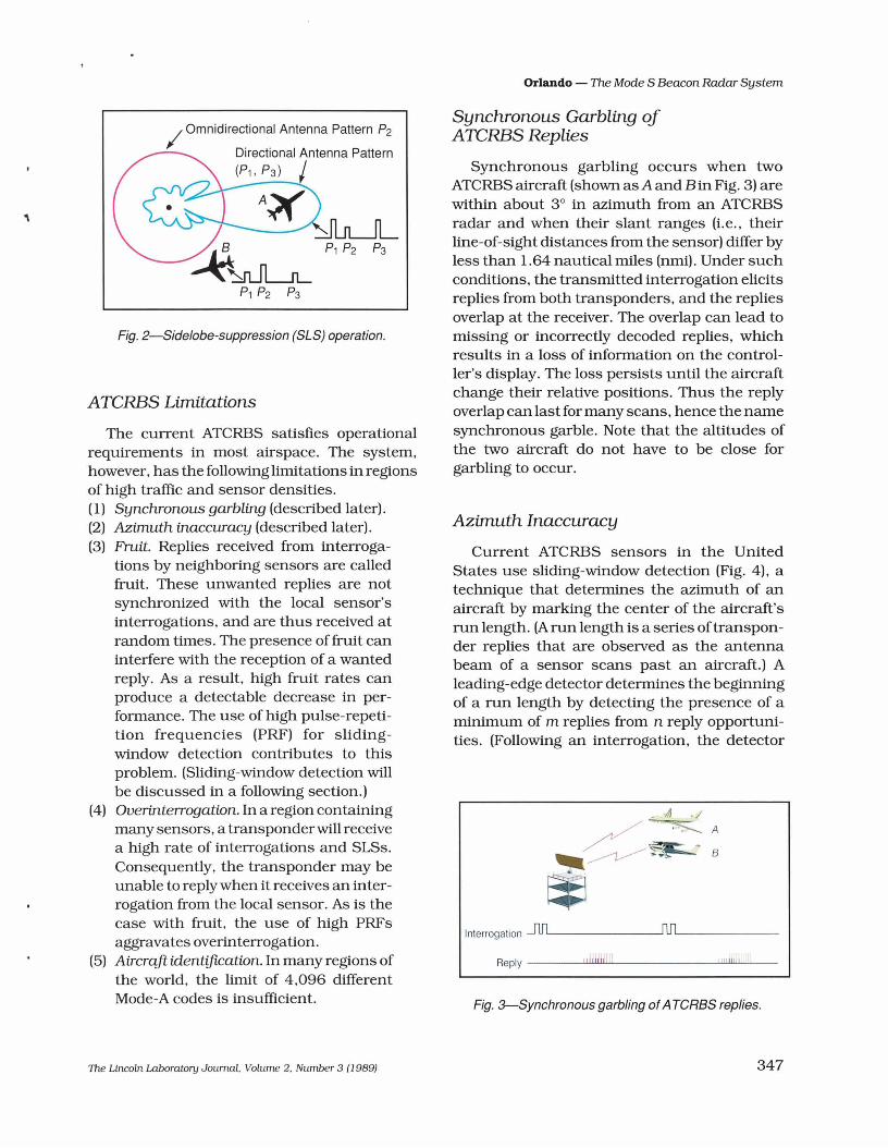
Synchronous garbling occurs when twoATCRBS aircraft (shown asA and Bin Fig. 3) arewithin about 3° in azimuth from an ATCRBSradar and when their slant ranges (Le., theirline-of-sight distances from the sensor) differ byless than 1.64 nautical miles (nmi). Under suchconditions, the transmitted interrogation elicitsreplies from both transponders, and the repliesoverlap at the receiver. The overlap can lead tomissing or incorrectly decoded replies, whichresults in a loss of information on the controller's display. The loss persists until the aircraftchange their relative positions. Thus the replyoverlap can last for many scans, hence the namesynchronous garble. Note that the altitudes ofthe two aircraft do not have to be close forgarbling to occur.
Azimuth Inaccuracy
Current ATCRBS sensors in the UnitedStates use sliding-window detection (Fig. 4), atechnique that determines the azimuth of anaircraft by marking the center of the aircraft'srun length. (A run length is a series oftransponder replies that are observed as the antennabeam of a sensor scans past an aircraft.) Aleading-edge detector determines the beginningof a run length by detecting the presence of aminimum of m replies from n reply opportunities. (Following an interrogation, the detector
Interrogation .-I1JlL rtllL _
Reply --lIl1JI!ll1JIIIILI lL'l .llJ1l'.L'__
Fig. 3-Synchronous garbling ofATeRBS replies.
347
Orlando - The Mode S Beacon Radar System
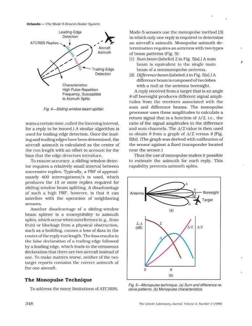
Fig. 5-Monopulse technique. (a) Sum and difference receive patterns. (b) Monopulse characteristics.
Antenna~~;a:~:~;9ht(a)
r
e(b)
o
L,.1(dB)
Mode-S sensors use the monopulse method [3]in which only one reply is reqUired to determinean aircraft's azimuth. Monopulse azimuth determination requires an antenna with two typesof beam patterns (Fig. 5):(1) Sum beam (labeled Lin Fig. 5[a].) A sum
beam is equivalent to the single mainbeam of a nonmonopulse antenna.
(2) Difference beam (labeled,1 in Fig. 5[a].) Adifference beam is composed oftwo lobeswith a null at the antenna boresight.
A reply received from a target that is an angleeoffboresight produces different signal amplitudes from the receivers associated with thesum and difference beams. The monopulseprocessor uses these amplitudes to calculate areturn signal that is a function of ,1/L, Le., theratio of the signal amplitudes in the differenceand sum channels. The ,1/L value is then usedto obtain e from a graph of ,1/L versus e (Fig.5[b]). (The graph was derived with calibration ofthe sensor against a fixed transponder locatednear the sensor.)
Thus the use of monopulse makes it possibleto estimate the azimuth for each reply. Thiscapability prevents azimuth splits.
AircraftAzimuth
To address the many limitations ofATCRBS,
Characteristics:High Pulse-RepetitionFrequency, Susceptibleto Azimuth Splits
waits a certain time, called the listening interval,for a reply to be issued.) A similar algorithm isused for trailing-edge detection. Once the leading and trailing edges have been determined, theaircraft azimuth is calculated as the center ofthe run length with an offset to account for thebias that the edge detectors introduce.
To ensure accuracy, a sliding-window detector requires a relatively small interval betweensuccessive replies. Typically, a PRF of approximately 400 interrogations/s is used, whichproduces the 15 or more replies required forsliding-window beam splitting. A disadvantageof such a high PRF, however, is that it caninterfere with the operation of neighboringsensors.
Another disadvantage of a sliding-windowbeam splitter is a susceptibility to azimuthsplits, which occur when interference (e.g., fromfruit) or blockage from a physical obstruction,such as a building, causes a loss of data in thecenter ofthe reply run length. The loss results inthe false declaration of a trailing edge followedby a leading edge, which leads to the erroneousdeclaration that there are two aircraft instead ofone. To make matters worse, neither of the twotarget reports contains the correct azimuth ofthe one aircraft.
Fig. 4-Sliding-window beam splitter.
The Monopulse Technique
348 The Lincoln Laboratory Journal. Volume 2. Number 3 (1989)
Orlando - The Mode S Beacon Radar System
,
ATCRBS Monopulse AzimuthDetermination
Monopulse makes surveillance of ATCRBSaircraft at very low interrogation rates possible.In theory. monopulse surveillance can be performed with as little as one Mode-A and oneMode-C reply opportunity per scan. In practice.however. additional replies are needed to ensurecorrect Mode-A and Mode-C code reception andto suppress false alarms. The Mode-S sensorinterrogates at a rate sufficient to elicit tworeplies for each ATCRBS mode within theATCRBS antenna's 3-dB beamwidth of 2.4°.This capability leads to a PRF of approximately100 pulses/so which is about one-quarter of thecurrent interrogation rate of ATCRBS.
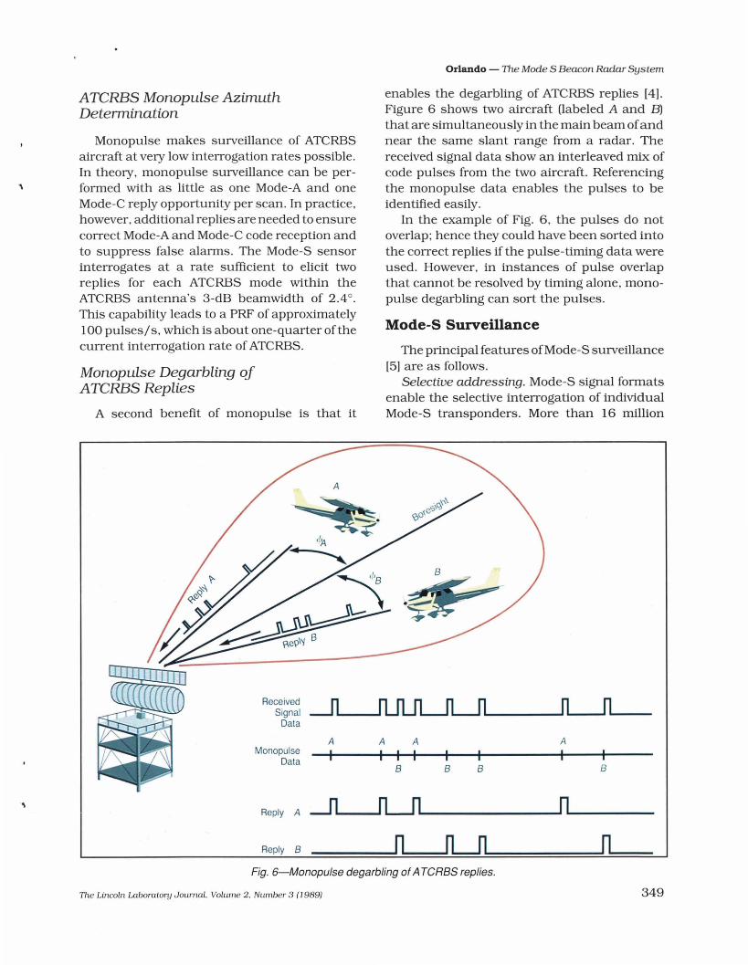
Monopulse Degarbling ofATCRBS Replies
A second benefit of monopulse is that it
enables the degarbling of ATCRBS replies [4).Figure 6 shows two aircraft (labeled A and B)that are simultaneously in the main beam ofandnear the same slant range from a radar. Thereceived signal data show an interleaved mix ofcode pulses from the two aircraft. Referencingthe monopulse data enables the pulses to beidentified easily.
In the example of Fig. 6. the pulses do notoverlap; hence they could have been sorted intothe correct replies if the pulse-timing data wereused. However. in instances of pulse overlapthat cannot be resolved by timing alone. monopulse degarbling can sort the pulses.
Mode-S Surveillance
The principal features ofMode-S surveillance[5) are as follows.
Selective addressing. Mode-S signal formatsenable the selective interrogation of individualMode-S transponders. More than 16 million
B
rLJl
BB
A A
I I IA
I
A -ll"'----'rLJll....- _
n
ReceivedSignal
Data
Reply B
Reply
MonopulseData
Fig. 6-Monopulse degarbling ofATeRBS replies.
The Lincoln Laboratory Journal. Volume 2. Number 3 (1989)
Orlando - The Mode S Beacon Radar System
The Lincoln Laboratory Journal. Volume 2. Number 3 (J 989)
REPLY
r
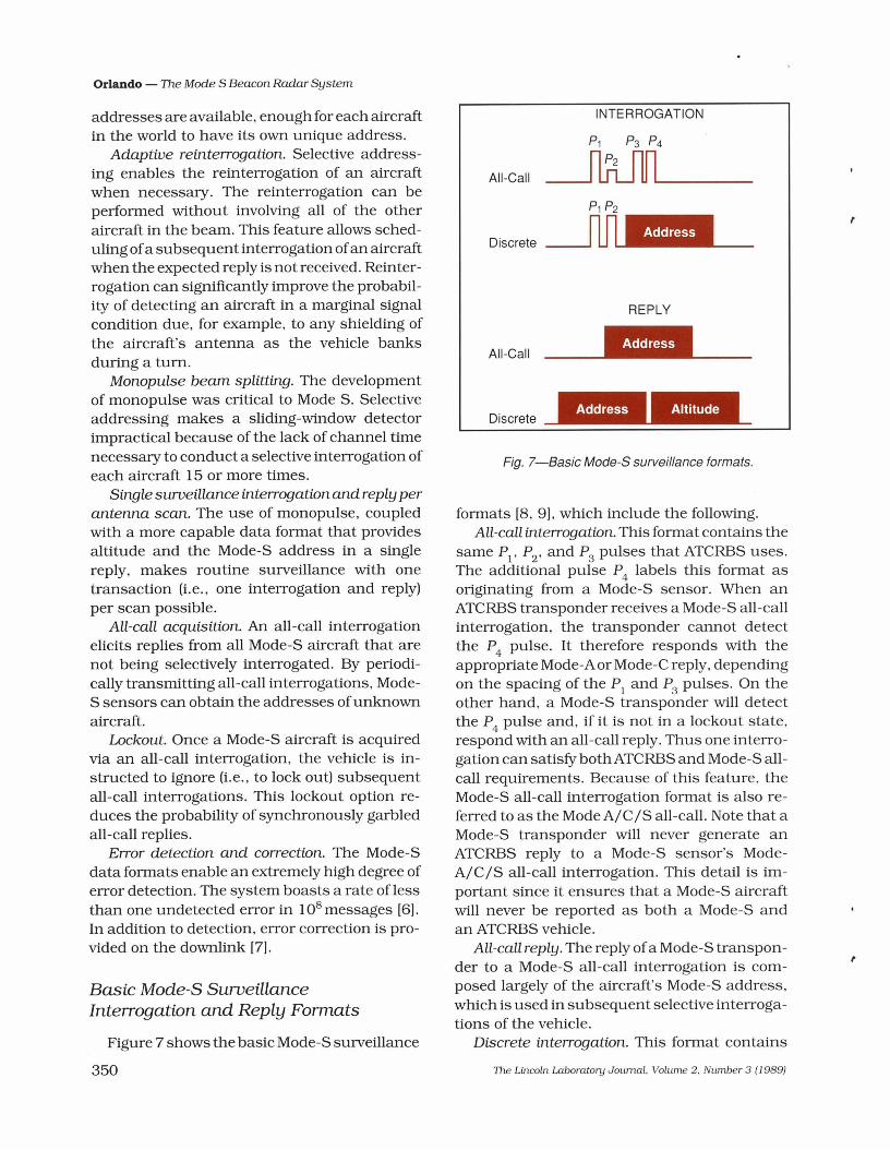
formats [8, 9], which include the following.All-call interrogation. This format contains the
same Pj
, P2
, and P3
pulses that ATCRBS uses.The additional pulse P
4labels this format as
originating from a Mode-S sensor. When anATCRBS transponder receives a Mode-S all-callinterrogation, the transponder cannot detectthe P
4pulse. It therefore responds with the
appropriate Mode-A or Mode-C reply, dependingon the spacing of the P
jand P
3pulses. On the
other hand, a Mode-S transponder will detectthe P
4pulse and, if it is not in a lockout state,
respond with an all-call reply. Thus one interrogation can satisfybothATCRBS and Mode-S allcall requirements. Because of this feature. theMode-S all-call interrogation format is also referred to as the Mode A/C/S all-call. Note that aMode-S transponder will never generate anATCRBS reply to a Mode-S sensor's ModeA/C/S all-call interrogation. This detail is important since it ensures that a Mode-S aircraftwill never be reported as both a Mode-S andan ATCRBS vehicle.
All-call reply. The reply ofa Mode-S transponder to a Mode-S all-call interrogation is composed largely of the aircraft's Mode-S address.which is used in subsequent selective interrogations of the vehicle.
Discrete interrogation. This format contains
Discrete
Fig. 7-Basic Mode-S surveillance formats.
All-Call
INTERROGATION
All-Call
Discrete
Basic Mode-S SurveillanceInterrogation and Reply Formats
addresses are available, enough for each aircraftin the world to have its own unique address.
Adaptive reinterrogation. Selective addressing enables the reinterrogation of an aircraftwhen necessary. The reinterrogation can beperformed without involving all of the otheraircraft in the beam. This feature allows scheduling ofa subsequent interrogation ofan aircraftwhen the expected reply is not received. Reinterrogation can significantly improve the probability of detecting an aircraft in a marginal signalcondition due, for example, to any shielding ofthe aircraft's antenna as the vehicle banksduring a tum.
Monopulse beam splitting. The developmentof monopulse was critical to Mode S. Selectiveaddressing makes a sliding-window detectorimpractical because of the lack of channel timenecessary to conduct a selective interrogation ofeach aircraft 15 or more times.
Single surveillance interrogation and reply perantenna scan. The use of monopulse, coupledwith a more capable data format that providesaltitude and the Mode-S address in a singlereply, makes routine surveillance with onetransaction (Le., one interrogation and reply)per scan possible.
All-call acquisition. An all-call interrogationelicits replies from all Mode-S aircraft that arenot being selectively interrogated. By periodically transmitting all-call interrogations, ModeS sensors can obtain the addresses ofunknownaircraft.
Lockout. Once a Mode-S aircraft is acqUiredvia an all-call interrogation, the vehicle is instructed to ignore (Le., to lock out) subsequentall-call interrogations. This lockout option reduces the probability of synchronously garbledall-call replies.
Error detection and correction. The Mode-Sdata formats enable an extremely high degree oferror detection. The system boasts a rate oflessthan one undetected error in 108 messages (6).In addition to detection, error correction is provided on the downlink (7).
Figure 7 shows the basic Mode-S surveillance
350
the Mode-S address of the aircraft for which theinterrogation is intended, surveillance information, and communication-control information.
Discrete reply. The basic surveillance reply toa discrete interrogation contains the aircraft'saltitude code and Mode-S address.
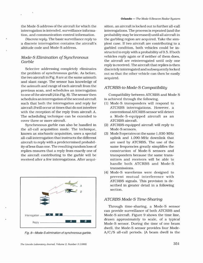
Mode-S Elimination ofSynchronousGarble
Selective addressing completely eliminatesthe problem of synchronous garble. As before,the two aircraft in Fig. 8 are at the same azimuthand slant range. The sensor has knowledge ofthe azimuth and range of each aircraft from theprevious scan, and schedules an interrogationto one ofthe aircraft (A in Fig. 8). The sensor thenschedules an interrogation ofthe second aircraftsuch that both the interrogation and reply foraircraft Bwill occur at times that do not interferewith the reception of the reply from aircraft A.The scheduling technique can be extended tocover three or more aircraft.
Synchronous garble can also be handled inthe all-call acquisition mode. The technique,known as stochastic acquisition, uses a specialall-call interrogation that instructs the differentaircraft to reply with a predetermined probability ofless than one. The resulting random loss ofreplies ensures that a reply from exactly one ofthe aircraft contributing to the garble will bereceived after a few interrogations. Mter acqui-
A
B
Interrogation --"-..'---,"~:---------
Reply --.l-.·~·-.L.-.:iI-.
Fig. 8-Mode-S elimination of synchronous garble.
The Lincoln Laboratory Journal. Volume 2. Number 3 (1989)
Orlando - The Mode S Beacon Radar System
sition, an aircraft is locked out to further all-callinterrogations. The process is repeated (and theprobability may be increased) until all aircraft inthe garbling region are acquired. Take the simplest case. If two aircraft are contributing to agarbled condition, both vehicles could be instructed to reply with a probability of0.5. Ifbothvehicles reply again or if neither of them does,the aircraft are reinterrogated until only onereply is received. The aircraft that replies is thendiscretely interrogated and subsequently lockedout so that the other vehicle can then be easilyacquired.
ATCRBS-to-Mode-S Compatibility
Compatibility between ATCRBS and Mode Sis achieved through the following.(1) Mode-S transponders will respond to
ATCRBS interrogations. However, aconventional ATCRBS sensor will detecta Mode-S-equipped aircraft as anATCRBS aircraft.
(2) ATCRBS-equipped aircraft will reply toMode-S sensors.
(3) Mode S operates on the same I,030-MHzuplink and I,090-MHz downlink thatare used by ATCRBS. The use of thesame frequencies greatly simplifies theconstruction of Mode-S sensors andtransponders because the same transmitters and receivers will be able tohandle both ATCRBS and Mode-Stransmissions.
(4) Mode-S waveforms were designed toprevent mutual interference withATCRBS signals. This provision is described in greater detail in a followingsection.
ATCRBS Mode-S Time-Sharing
Through time-sharing, a Mode-S sensorcan provide surveillance of both ATCRBS andMode-S aircraft. Figure 9 shows the time line,drawn approximately to scale, of a typicalMode-S sensor. During the time of one beamdwell, the Mode-S sensor provides four ModeA/C/S all-call periods. (A beam dwell is the
351
Orlando - The Mode S Beacon Radar System
Fig. 9-ATCRBS-Mode-S time sharing.
typical time, approximately 30 ms for a terminalsensor, that a beam is actually on an aircraft.)This scheduling provides the interrogation andlistening intervals required by the mandatorytwo Mode-A and two Mode-C replies. All-call acquisition is also performed dUring this time.
Selective Mode-S interrogations are scheduled during the Mode-S roll-call periods. Notethat the use of monopulse for ATCRBS enablesthe sensor to devote most of the time line toMode S.
I+-Beam-Dwell Time---l
/ATCRBS/Mode-s All-Call Periods
'Mode-S Roll-Call Periods
Time
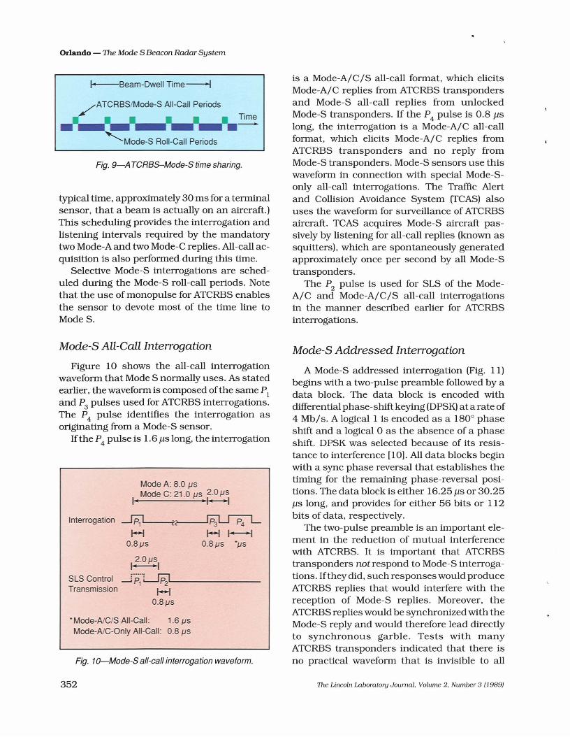
is a Mode-A/C/S all-call format. which elicitsMode-A/C replies from ATCRBS transpondersand Mode-S all-call replies from unlockedMode-S transponders. If the P
4pulse is 0.8 ).lS
long, the interrogation is a Mode-A/C all-callformat, which elicits Mode-A/C replies fromATCRBS transponders and no reply fromMode-S transponders. Mode-S sensors use thiswaveform in connection with special Mode-Sonly all-call interrogations. The Traffic Alertand Collision Avoidance System (TCAS) alsouses the waveform for surveillance of ATCRBSaircraft. TCAS acquires Mode-S aircraft passively by listening for all-call replies (known assquitters), which are spontaneously generatedapproximately once per second by all Mode-Stransponders.
The Pz pulse is used for SLS of the ModeA/C and Mode-A/C/S all-call interrogationsin the manner described earlier for ATCRBSinterrogations.
Mode-S All-Call Interrogation
Figure 10 shows the all-call interrogationwaveform that Mode S normally uses. As statedearlier, the waveform is composed ofthe same PIand P3 pulses used for ATCRBS interrogations.The P
4pulse identifies the interrogation as
originating from a Mode-S sensor.If the P
4pulse is 1.6 ).ls long, the interrogation
Mode A: 8.0 JJsMode C: 21.0 JJs 2.0 JJs
I' • I • .,
Interrogation~~
1-1 1-1 I-t0.8 JJs 0.8 JJs *JJs
I~.O JJ~I
SLS Control .-J'P~'L...JP;1'---------Transmission I-f
0.8 JJs
* Mode-AIC/S All-Call: 1.6 JJsMode-AlC-Only All-Call: 0.8 JJs
Fig. 1Q-Mode-S all-call interrogation waveform.
352
Mode-S Addressed Interrogation
A Mode-S addressed interrogation (Fig. 11)begins with a two-pulse preamble followed by adata block. The data block is encoded withdifferential phase-shift keying (DPSK) at a rate of4 Mb/s. A logical 1 is encoded as a 1800 phaseshift and a logical 0 as the absence of a phaseshift. DPSK was selected because of its resistance to interference [10]. All data blocks beginwith a sync phase reversal that establishes thetiming for the remaining phase-reversal positions. The data block is either 16.25).ls or 30.25).ls long, and provides for either 56 bits or 112bits of data. respectively.
The two-pulse preamble is an important element in the reduction of mutual interferencewith ATCRBS. It is important that ATCRBStransponders not respond to Mode-S interrogations. Ifthey did, such responses would produceATCRBS replies that would interfere with thereception of Mode-S replies. Moreover, theATCRBS replies would be synchronized with theMode-S reply and would therefore lead directlyto synchronous garble. Tests with manyATCRBS transponders indicated that there isno practical waveform that is invisible to all
TIle Lincoln Laboratory Journal. Volume 2. Number 3 (1989)

Preamble3.5 J.1s
• 2.0 J.1s _I
Orlando - The Mode S Beacon Radar System
Data Block16.25 or 30.25 J.1s
Sync Phase Reversal1.25 J.1S
1
~~~ 56 or 112 Data / / /Phase-Reversal Positions
___S_L_S_c_o_n_tr_o_I_T_ra_n_s_m_is_s_io_n_---'Ae.- _
• Differential Phase-Shift Keying (DPSK) Modulation
• Data Rate: 4 Mb/s
Fig. 11-Mode-S interrogation waveform.
ATCRBS transponders. Consequently, the approach that was adopted was to precede theMode-S data block with a preamble consisting ofa P
jand P
2pulse of equal amplitude. When
received by an ATCRBS transponder, thesepulses put the transponder into a period ofsuppression for 35 )1s. The data block is sentdUring this interval and is therefore undetectable by the ATCRBS transponder. Note that thelength of the suppression interval dictated themaximum length of the Mode-S data block.
SLS is not required with a selectively addressed Mode-S interrogation, since the interrogation is transmitted while the addressed aircraft is in the main beam of the antenna. Also,other Mode-S aircraft in the antenna sideloberegions that receive the interrogation will notreply, since the interrogation does not containtheir Mode-S address.
On the other hand, the Mode-S-only all-callformat requires SLS. The P
2pulse cannot be
used for SLS because it is used in the Mode-Spreamble to prevent ATCRBS replies to Mode-Sinterrogations. Thus SLS for Mode S is providedby an additional pulse, which is shown as P
5in
Fig. 11. This pulse is transmitted in an omnipattern at the time of the sync phase reversal. Thepresence of P
5obliterates the sync phase rever
sal for aircraft in the sidelobes, an action thatmakes decoding the interrogation impossible.
The Lincoln Laboratory Journal. Volume 2. Number 3 (1989)
Note that the Mode-S transponder does notrequire any SLS circuitry because the suppression occurs through controlled interference ofthe sync phase reversal. However, since P5 mustbe transmitted at the same time as the datablock, a second transmitter (of a much lowerduty cycle than the main transmitter) is neededin the Mode-S sensor.
Mode-S Reply
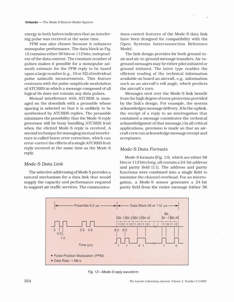
A Mode-S reply (Fig. 12) begins with a fourpulse preamble followed by a data block. Thedata block is encoded with pulse-positionmodulation (PPM) at a rate of 1 Mb/s-thehighest rate compatible with a low-cost implementation for the Mode-S transponder. In PPM,a logical 1 is encoded as the presence ofa 0.5-)1spulse in the first half of the 1-)1s data interval ofFig. 12. A logical 0 is encoded as the presence ofa 0.5-)1s pulse in the second half of the interval.The data block is either 56 )1S or 112 )1s long,thus providing either 56 data bits or twice thatamount.
PPM was chosen because it provides bitinterference detection. PPM detects interferenceof a data-bit position by comparing the receivedenergy in both halves of the data chip interval.The absence of interference results in receivedenergy in only one half of the interval. Thus
353
Orlando - The Mode S Beacon Radar System
energy in both halves indicates that an interfering pulse was received at the same time.
PPM was also chosen because it enhancesmonopulse performance. The data block in Fig.12 contains either 56 bits or 112 bits, independent of the data content. The constant number ofpulses makes it possible for a monopulse azimuth estimate for the PPM reply to be basedupon a large number (e.g., 16 or 32) ofindividualpulse azimuth measurements. This featurecontrasts with the pulse-amplitude modulationofATCRBS in which a message composed of alllogical as does not contain any data pulses.
Mutual interference with ATCRBS is managed on the downlink with a preamble whosespacing is selected so that it is unlikely to besynthesized by ATCRBS replies. The preambleminimizes the possibility that the Mode-S replyprocessor will be busy handling ATCRBS fruitwhen the elicited Mode-S reply is received. Asecond technique for managing mutual interference is called burst error correction, which canerror-correct the effects ofa single ATCRBS fruitreply received at the same time as the Mode-Sreply.
Mode-S Data Link
The selective addressing ofMode S provides anatural mechanism for a data link that wouldsupply the capacity and performance requiredto support air traffic services. The communica-
tions-control features of the Mode-S data linkhave been designed for compatibility with theOpen Systems Interconnection ReferenceModel.
The link design provides for both ground-toair and air-to-ground message transfers. Air-toground messages may be either pilot initiated orground initiated. The latter type enables theefficient reading of the technical informationavailable on board an aircraft, e.g., informationsuch as an aircraft's roll angle, which predictsthe aircraft's tum.
Messages sent over the Mode-S link benefitfrom the high degree oferror protection providedby the link's design. For example, the systemacknowledges message delivery. (On the uplink,the receipt of a reply to an interrogation thatcontained a message constitutes the technicalacknowledgment of that message.) In all criticalapplications, provision is made so that an aircraft crew can acknowledge message receipt andacceptance.
Mode-S Data Formats
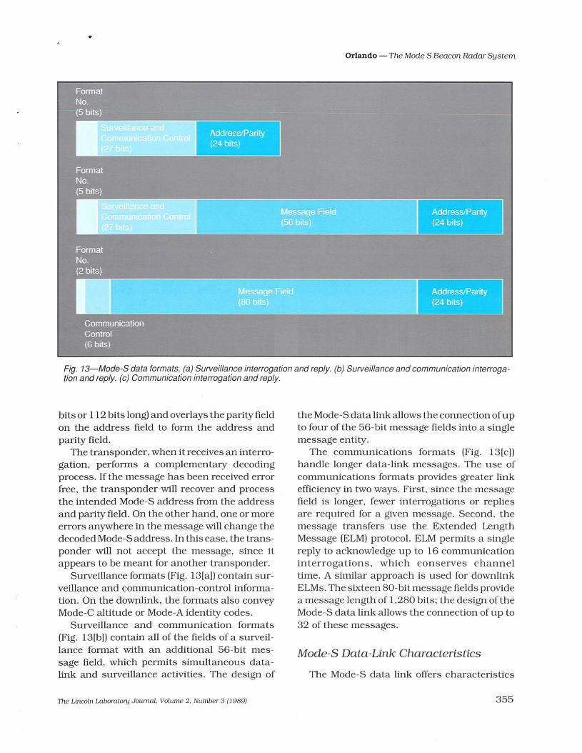
Mode-S formats (Fig. 13), which are either 56bits or 112 bits long, all contain a 24-bit addressand parity field [11]. The address and parityfunctions were combined into a single field tominimize the channel overhead. For an interrogation, a Mode-S sensor generates a 24-bitparity field from the entire message (either 56
1.....4~--- Preamble 8.0 Jls ----i..~r-- Data Siock 56 or 112 JlS4Sit
ISit 11Sit 21Sit 31Sit 41 IN -1 Isit NIJ1Jl IUl :1:-0: -1-: 0-:1-:0:1-:0:- -: --r -:-1-: 0-:1:-6:6 0~51 --3:5 4:5 ---~8io---":""9~io""""""'~I-~1 ~~C2-2~1~I~~I~I-
1.0 ~~Time (J1s) 1 1 a 1 1 0
• Pulse-Position Modulation (PPM)
• Data Rate: 1 Mb/s
Fig. 12-Mode-S reply waveform.
354 The Lincoln Laboratory Journal. Volume 2. Number 3 (1989)
Orlando - The Mode S Beacon Radar System
. .• •
Fig. 13-Mode-S data formats. (a) Surveillance interrogation and reply. (b) Surveillance and communication interrogation and reply. (c) Communication interrogation and reply.
bits or 112 bits long) and overlays the parity fieldon the address field to form the address andparity field.
The transponder, when it receives an interrogation, performs a complementary decodingprocess. If the message has been received errorfree, the transponder will recover and processthe intended Mode-S address from the addressand parity field. On the other hand, one or moreerrors anywhere in the message will change thedecoded Mode-S address. In this case, the transponder will not accept the message, since itappears to be meant for another transponder.
Surveillance formats (Fig. 13[a]) contain surveillance and communication-control information. On the downlink, the formats also conveyMode-C altitude or Mode-A identity codes.
Surveillance and communication formats(Fig. 13[b]) contain all of the fields of a surveillance format with an additional 56-bit message field, which permits simultaneous datalink and surveillance activities. The design of
The Lincoln Laboratory Journal, Volume 2, Number 3 (1989)
the Mode-S data link allows the connection ofupto four of the 56-bit message fields into a singlemessage entity.
The communications formats (Fig. 13[c])handle longer data-link messages. The use ofcommunications formats provides greater linkefficiency in two ways. First, since the messagefield is longer, fewer interrogations or repliesare required for a given message. Second, themessage transfers use the Extended LengthMessage (ELM) protocol. ELM permits a singlereply to acknowledge up to 16 communicationinterrogations, which conserves channeltime. A similar approach is used for downlinkELMs. The sixteen 80-bit message fields providea message length of 1,280 bits; the design of theMode-S data link allows the connection of up to32 of these messages.
Mode-S Data-Link Characteristics
The Mode-S data link offers characteristics
355
Orlando - The Mode S Beacon Radar System
that are well suited to the needs of air trafficservices. For instance, the association of theMode-S data link with the surveillance functionoffers a number of operational benefits. Communication with an aircraft can be establishedbased solely on surveillance detection. Thus amessage can be sent to an otherwise unidentified aircraft. This capability is important forsafety services; e.g., warnings can be sent to anunidentified aircraft that is flying too low or thatis heading into controlled airspace. Since thesame address is used for both surveillance andcommunication, the possibility of sending amessage to the wrong aircraft because of anerror in cross-referencing the surveillance andcommunication identities is eliminated. A further operational benefit is that communicationscoverage is assured whenever surveillancecoverage exists.
Because of the inherent characteristics ofMode-S sensors, the Mode-S link discouragesboth accidental and intentional jamming. Witha Mode-S radar, coverage is restricted to thesensor's line of sight. This restriction limits notonly the airspace in which the sensor can covertraffic, but also the area in which an interferingsource can affect the sensor. A narrow antennabeam further limits the active area. Thus asingle interfering source, if it is outside thesidelobe region of the sensor, will preventoperation in only a single antenna beamwidth.In the worst case, in which the interferingsource is within the sidelobe region (i.e., withina distance of about five miles from the sensor),the source could prevent operation of that sensor in all directions. However, the interferingsource would have little effect on the operation of all other Mode-S sensors. Thus thedistributed nature of Mode S makes it tolerantof interference.
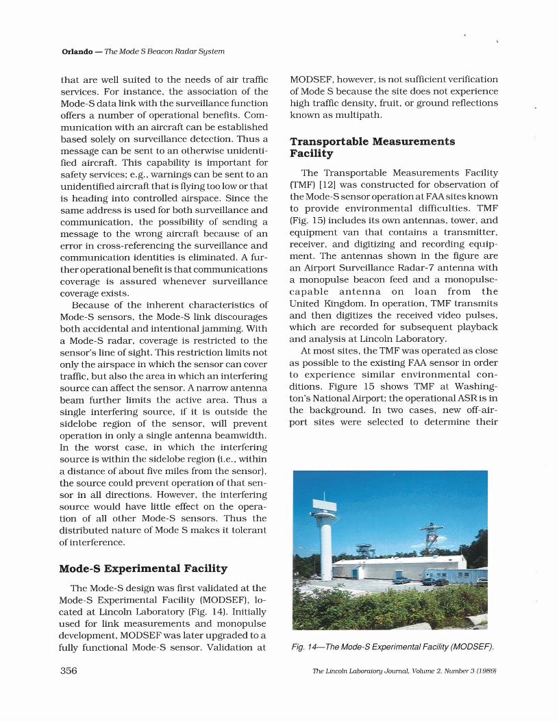
Mode-S Experimental Facility
The Mode-S design was first validated at theMode-S Experimental Facility (MODSEF), located at Lincoln Laboratory (Fig. 14). Initiallyused for link measurements and monopulsedevelopment, MODSEF was later upgraded to afully functional Mode-S sensor. Validation at
356
MODSEF, however, is not sufficient verificationof Mode S because the site does not experiencehigh traffic density, fruit, or ground reflectionsknown as multipath.
Transportable MeasurementsFacility
The Transportable Measurements Facility(TMF) [12) was constructed for observation ofthe Mode-S sensor operation at FAA sites knownto provide environmental difficulties. TMF(Fig. 15) includes its own antennas, tower, andequipment van that contains a transmitter,receiver, and digitizing and recording equipment. The antennas shown in the figure arean Airport Surveillance Radar-7 antenna witha monopulse beacon feed and a monopulsecapable antenna on loan from theUnited Kingdom. In operation, TMF transmitsand then digitizes the received video pulses,which are recorded for subsequent playbackand analysis at Lincoln Laboratory.
At most sites, the TMF was operated as closeas possible to the existing FAA sensor in orderto experience similar environmental conditions. Figure 15 shows TMF at Washington's National Airport; the operational ASRis inthe background. In two cases, new off-airport sites were selected to determine their
Fig. 14-The Mode-S Experimental Facility (MODSEF).
The Lincoln Laboratory Journal. Volume 2. Number 3 (1989)
•Orlando - The Mode S Beacon Radar System
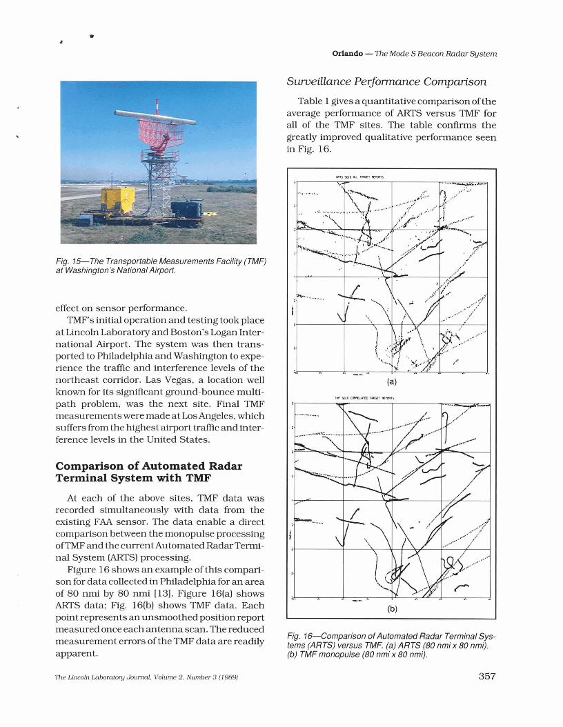
Surveillance Performance Comparison
Fig. 16-Comparison ofAutomated Radar Terminal Systems (ARTS) versus TMF. (a) ARTS (80 nmi x 80 nmi).(b) TMF monopulse (80 nmi x 80 nmi).
....'-.-(If.
. ,"r.,
.._..."...,..::;,;;:l.'
l-'
......:::.:.1.·..... "
~ ..... , ,....:'
' .... ~ ......"
(b)
(a)
,..- SOIl> COMHA1(O lA"l(Zl I'l£l'OI"TS
MTSSOI6I:l.lTI¥I(£1P{"POI'I1S
~ ... " .... , ...
;..
Table 1 gives a quantitative comparison oftheaverage performance of ARTS versus TMF forall of the TMF sites. The table confirms thegreatly improved qualitative performance seenin Fig. 16.
Fig. 15-The Transportable Measurements Facility (TMF)at Washington's National Airport.
Comparison of Automated RadarTerminal System with TMF
At each of the above sites, TMF data wasrecorded simultaneously with data from theexisting FAA sensor. The data enable a directcomparison between the monopulse processingofTMF and the currentAutomated RadarTerminal System (ARTS) processing.
Figure 16 shows an example of this comparison for data collected in Philadelphia for an areaof 80 nmi by 80 nmi (13). Figure 16(a) showsARTS data; Fig. 16(b) shows TMF data. Eachpoint represents an unsmoothed position reportmeasured once each antenna scan. The reducedmeasurement errors of the TMF data are readilyapparent.
effect on sensor performance.TMF's initial operation and testing took place
at Lincoln Laboratory and Boston's Logan International Airport. The system was then transported to Philadelphia and Washington to experience the traffic and interference levels of thenortheast corridor. Las Vegas, a location wellknown for its significant ground-bounce multipath problem, was the next site. Final TMFmeasurements were made at Los Angeles, whichsuffers from the highest airport traffic and interference levels in the United States.
-,
The Lincoln Laboratory Journal. Volume 2. NlLmber 3 (J 989) 357
Orlando - The Mode S Beacon Radar System
Table 1. Surveillance Performance Comparison
Arts TMF Monopulse
All Crossing All Crossing
Blip/Scan 94.6% 86.9% 98.0% 96.6%
Azimuth Error (1 a) 0.16° 0.04°
Range Error (1 a) 124 ft 24 ft
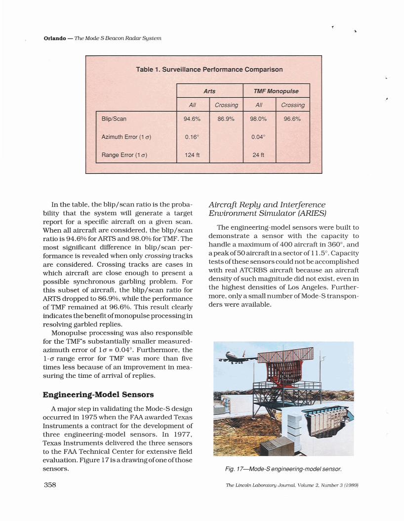
In the table, the blip/scan ratio is the probability that the system will generate a targetreport for a specific aircraft on a given scan.When all aircraft are considered, the blip/scanratio is 94.6% for ARTS and 98.0% forTMF. Themost significant difference in blip/scan performance is revealed when only crossing tracksare considered. Crossing tracks are cases inwhich aircraft are close enough to present apossible synchronous garbling problem. Forthis subset of aircraft, the blip/scan ratio forARTS dropped to 86.9%, while the performanceof TMF remained at 96.6%. This result clearlyindicates the benefit ofmonopulse processing inresolving garbled replies.
Monopulse processing was also responsiblefor the TMF's substantially smaller measuredazimuth error of 10" = 0.04°. Furthermore, the1-0" range error for TMF was more than fivetimes less because of an improvement in measuring the time of arrival of replies.
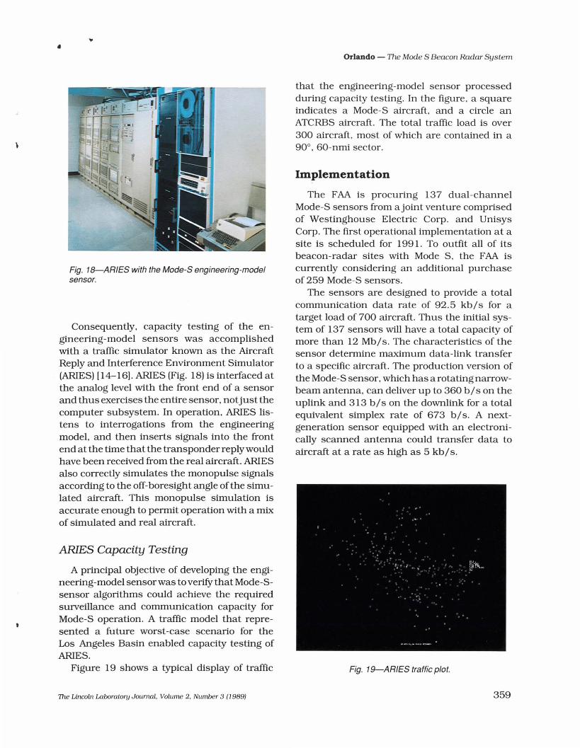
Engineering-Model Sensors
A major step in validating the Mode-S designoccurred in 1975 when the FAA awarded TexasInstruments a contract for the development ofthree engineering-model sensors. In 1977,Texas Instruments delivered the three sensorsto the FAA Technical Center for extensive fieldevaluation. Figure 17 is a drawing ofone ofthosesensors.
358
Aircraft Reply and InterferenceEnvironment Simulator (ARIES)
The engineering-model sensors were built todemonstrate a sensor with the capacity tohandle a maximum of 400 aircraft in 360°, andapeak of50 aircraft in a sector of 11.5°. Capacitytests of these sensors could not be accomplishedwith real ATCRBS aircraft because an aircraftdensity of such magnitude did not exist. even inthe highest densities of Los Angeles. Furthermore, only a small number of Mode-S transponders were available.
Fig. 17-Mode-S engineering-model sensor.
The Lincoln Laboratory Joumal. Volume 2. Number 3 (1989)
•
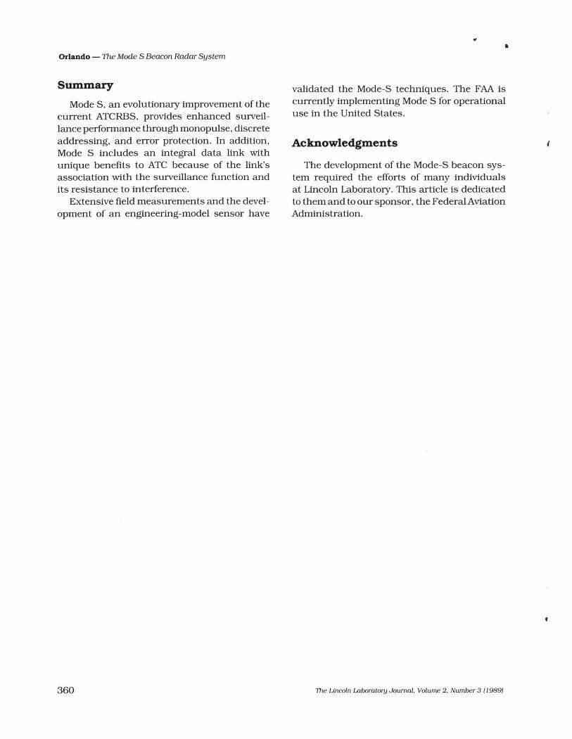
Fig. 18-ARIES with the Mode-S engineering-modelsensor.
Consequently, capacity testing of the engineering-model sensors was accomplishedwith a traffic simulator known as the AircraftReply and Interference Environment Simulator(ARIES) [14-16). ARIES (Fig. 18) is interfaced atthe analog level with the front end of a sensorand thus exercises the entire sensor. notjust thecomputer subsystem. In operation. ARIES listens to interrogations from the engineeringmodel, and then inserts signals into the frontend at the time that the transponder reply wouldhave been received from the real aircraft. ARIESalso correctly simulates the monopulse signalsaccording to the off-boresight angle of the simulated aircraft. This monopulse simulation isaccurate enough to permit operation with a mixof simulated and real aircraft.
ARIES Capacity Testing
A principal objective of developing the engineering-model sensorwas to verifY that Mode-Ssensor algorithms could achieve the reqUiredsurveillance and communication capacity forMode-S operation. A traffic model that represented a future worst-case scenario for theLos Angeles Basin enabled capacity testing ofARIES.
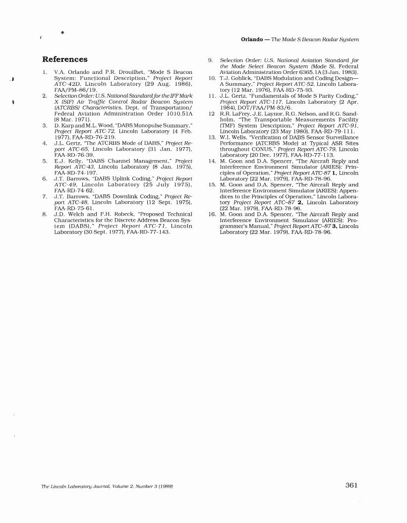
Figure 19 shows a typical display of traffic
The Lincoln Laboratory Journal. Volume 2. Number 3 (J 989;
Orlando - The Mode S Beacon Radar System
that the engineering-model sensor processedduring capacity testing. In the figure, a squareindicates a Mode-S aircraft. and a circle anATCRBS aircraft. The total traffic load is over300 aircraft, most of which are contained in a90°, 60-nmi sector.
Implementation
The FAA is procuring 137 dual-channelMode-S sensors from ajoint venture comprisedof Westinghouse Electric Corp. and UnisysCorp. The first operational implementation at asite is scheduled for 1991. To outfit all of itsbeacon-radar sites with Mode S. the FAA iscurrently considering an additional purchaseof 259 Mode-S sensors.
The sensors are designed to provide a totalcommunication data rate of 92.5 kbls for atarget load of 700 aircraft. Thus the initial system of 137 sensors will have a total capacity ofmore than 12 Mb/s. The characteristics of thesensor determine maximum data-link transferto a specific aircraft. The production version ofthe Mode-S sensor, which has a rotating narrowbeam antenna, can deliver up to 360 bls on theuplink and 313 bls on the downlink for a totaleqUivalent simplex rate of 673 b/s. A nextgeneration sensor eqUipped with an electronically scanned antenna could transfer data toaircraft at a rate as high as 5 kb/s.
Fig. 19-ARIES traffic plot.
359
Orlando - The Mode S Beacon Radar System
Summary
Mode S, an evolutionary improvement of thecurrent ATCRBS, provides enhanced surveillance performance through monopulse, discreteaddressing, and error protection. In addition,Mode S includes an integral data link withunique benefits to ATC because of the link'sassociation with the surveillance function andits resistance to interference.
Extensive field measurements and the development of an engineering-model sensor have
360
•
validated the Mode-S techniques. The FAA iscurrently implementing Mode S for operationaluse in the United States.
Acknowledgments
The development of the Mode-S beacon system required the efforts of many individualsat Lincoln Laboratory. This article is dedicatedto them and to our sponsor, the Federal AviationAdministration.
The Lincoln Laboratory JournaL Volume 2. Number 3 (1989)
•
References1. V.A. Orlando and P.R Drouilhet, "Mode S Beacon
System: Func~ional Description," Project ReportATC-42D, Lincoln Laboratory (29 Aug. 1986),FAA/PM-86/19.
2. Selection Order: U.S. National Standardfor the IFFMarkX (SIF) Air Traffic Control Radar Beacon System(ATCRBS) Characteristics, Dept. of Transportation/Federal Aviation Administration Order 1010.51A(8 Mar. 1971).
3. D. KarpandM.L. Wood, "DABS Monopulse Summary,"Project Report ATC-72, Lincoln Laboratory (4 Feb.1977), FAA-RD-76-219.
4. J.L. Gertz, "The ATCRBS Mode of DABS," Project Report ATC-65, Lincoln Laboratory (31 Jan. 1977),FAA-RD-76-39.
5. E.J. Kelly, "DABS Channel Management," ProjectReport ATC-43, Lincoln Laboratory (8 Jan. 1975),FAA-RD-74-197.
6. J.T. Barrows, "DABS Uplink Coding," Project ReportATC-49, Lincoln Laboratory (25 July 1975),FAA-RD-74-62.
7. J.T. Barrows, "DABS Downlink Coding," Project Report ATC-48, Lincoln Laboratory (12 Sept. 1975),FAA-RD-75-61.
8. J.D. Welch and P.H. Robeck, "Proposed TechnicalCharacteristics for the Discrete Address Beacon System (DABS)," Project Report ATC-71 , LincolnLaboratory (30 Sept. 1977), FAA-RD-77-143.
1he Lincoln Laboralory Journal. Volume 2, Number 3 (1989)
Orlando - The Mode S Beacon Radar System
9. Selection Order: U.S. National Aviation Standard forthe Mode Select Beacon System (Mode S), FederalAviation Administration Order 6365.1A (3 Jan. 1983).
10. T.J. Goblick, "DABS Modulation and Coding DesignA Summary," Project Report ATC-52, Lincoln Laboratory (12 Mar. 1976), FAA-RD-75-93.
11. J .L. Gertz, "Fundamentals of Mode S Parity Coding,"Project Report ATC-]] 7, Lincoln Laboratory (2 Apr.1984), DOT/FAA/PM-83/6.
12 RR LaFrey, J.E. Laynor, RG. Nelson, and RG. Sandholm, "The Transportable Measurements Facility(TMF) System Description," Project Report ATe-9] ,Lincoln Laboratory (23 May 1980), FAA-RD-79-111.
13. W.1. Wells, "Verification of DABS Sensor SurveillancePerformance (ATCRBS Mode) at Typical ASR Sitesthroughout CONUS," Project Report ATC-79, LincolnLaboratory (20 Dec. 1977), FAA-RD-77-113.
14. M. Goon and D.A. Spencer, "The Aircraft Reply andInterference Environment Simulator (ARlES): Principles of Operation," ProjectReportATC-871, LincolnLaboratory (22 Mar. 1979), FAA-RD-78-96.
15. M. Goon and D.A. Spencer, "The Aircraft Reply andInterference Environment Simulator (ARlES): Appendices to the Principles of Operation," Lincoln Laboratory Project Report ATC-87 2. Lincoln Laboratory(22 Mar. 1979), FAA-RD-78-96.
16. M. Goon and D.A. Spencer, ''The Aircraft Reply andInterference Environment Simulator (ARlES): Programmer's Manual," ProjectReportATe-873. LincolnLaboratory (22 Mar. 1979). FAA-RD-78-96.
361
Orlando - The Mode S Beacon Radar System
VINCENT A. ORLANDO iscurrently in charge of theSystem Design and Evaluation Group at LincolnLaboratory. where his research has focused on air
traffic safety and capacity. Before joining the Laboratory 17years ago. Vince spent 1Oyears working on the developmentof military command and control systems. He received aB.S. in electrical engineering from the University ofCincinnati, an M.S. in statistics from Stanford University. and aPh.D. in systems and information science from SyracuseUniversity. A member of Tau Beta Pi and Eta Kappa Nu.Vince was the recipient of a National Science FoundationTraineeship.
362
•
TIle Lincoln Laboratory Journal. Volume 2. Number 3 (1989)
l,
Recommended