The Milton S. Hershey Medical Center
Academic Support Building
AE Senior ThesisSpring 2003
Kari Anne DonovanMechanical Option
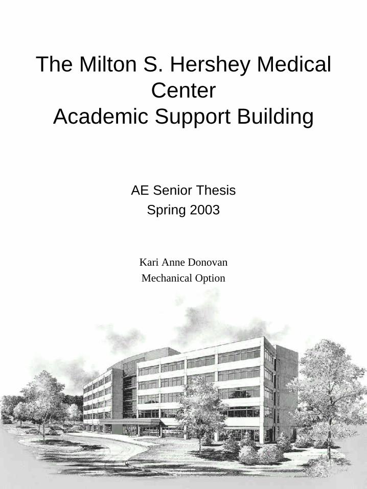
•Owner - The Pennsylvania State University•Architect - Williams Trebilcock and Whitehead•Construction Manager - Barclay-White, Incorporated•Site and Civil Engineers - Rettew Associates•Structural Engineers - Whitney Bailey Cox and Magnani•Mechanical and Electrical Engineers - Brinjac-Kambic Associates
The Milton S. Hershey Medical Center Academic Support BuildingHershey, PA
•ASTM A-36 structural steel columns and brackets•400psi elevated floor slabs on composite metal deck•1900psi foundation block walls
•15KVA transformer 13.8KV/480Y/277V•Main distribution board 2500amp, 480Y/277V main bus, metered•208Y/120 112.5KVA transformers on each floor•150KW roof mounted generator set•Moveable underfloor junction boxes housing outlet & data jacks•General interior lighting from compact fluorescent and T-8 lamps•Outside lighting is 175W metal halide post-top lighting
•Underfloor air distribution system•7,513 sq ft return air plenum mechanical penthouse•(4) 42,500/3,750 cfm minimum OAT AHUs w/ VFD fan motors and 400lb/hr gas fired humidifiers•(3) 48.2 boiler hp/1615 MBH gas fired boilers •(2) 225 ton packaged air-cooled chillers•27.1 ton reciprocating winter chiller w/ remote chiller barrel•12-16” perimeter hot water radiant heating panels
The Milton S. Hershey Medical Center Academic Support Building is a mixed use office building located on Penn State land in Hershey, PA. The 5 story, 145,316 gross sq. ft building houses departments for both Penn State College of Medicine and Hershey Medical Center. The 19 million dollar design-build project was designed to facilitate flexibility of the building program. Its central core houses an elevator bank, restrooms, a stairwell, and shared conference spaces. The angled wings contain suites with distinct entrances for each department.
•ASTM A-572 structural steel floor beams
Access flooring with underfloor ductwork and cable tray installed.
Floor diffuser and cable tray access.
Access flooring panel.
http://www.arche.psu.edu/thesis/kad202/
The Milton S. Hershey Medical Center Academic Support Building April 9, 2003
Kari Anne Donovan - Mechanical Option i
EXECUTIVE SUMMARY ........................................................................................... 1
BUILDING OVERVIEW ............................................................................................. 2
PRIMARY PROJECT TEAM ............................................................................................. 2 DESIGN PROCESS ......................................................................................................... 3 DESIGN OBJECTIVES AND REQUIREMENTS .................................................................... 3
Site Factors ............................................................................................................. 3 Central Utility Plant ................................................................................................ 4 Energy Sources and Rates ....................................................................................... 4
CONSTRUCTION SUMMARY........................................................................................... 5 Project Delivery System........................................................................................... 5 Dates of Construction.............................................................................................. 5 Cost Information ..................................................................................................... 6
ARCHITECTURE............................................................................................................ 6 BUILDING SYSTEMS ..................................................................................................... 7
Building Envelope ................................................................................................... 7 Electrical................................................................................................................. 8
Emergency Power................................................................................................ 8 Fire Alarm System............................................................................................... 8 Lighting............................................................................................................... 9 Underfloor Junction Boxes .................................................................................. 9 Telecommunications............................................................................................ 9
Mechanical.............................................................................................................. 9 Plumbing............................................................................................................... 10 Fire Protection ...................................................................................................... 11 Structural .............................................................................................................. 11 Conveying Systems ................................................................................................ 11
MECHANICAL SYSTEM - EXISTING.................................................................... 12
EXISTING SYSTEM SCHEMATICS AND SEQUENCES OF OPERATION ................................ 12 Air Handling System.............................................................................................. 12 Chilled Water System ............................................................................................ 16 Hot Water System .................................................................................................. 19
EXISTING SYSTEM CRITIQUE AND OPERATING HISTORY.............................................. 21
MECHANICAL SYSTEM – REDESIGN.................................................................. 23
DISTRIBUTED CHILLED WATER FEASIBILITY STUDY (AE DEPTH) ................................ 23 District Utilities..................................................................................................... 23 Central Utility Plant .............................................................................................. 26 System Comparison ............................................................................................... 27 Conclusion ............................................................................................................ 30
DEDICATED OUTDOOR AIR SYSTEM/RADIANT COOLING PANEL SYSTEM (AE DEPTH) . 30 Introduction........................................................................................................... 30 System Redesign .................................................................................................... 33
AHU Sequence of Operation ............................................................................. 34 Chilled Water System: ....................................................................................... 38
The Milton S. Hershey Medical Center Academic Support Building April 9, 2003
Kari Anne Donovan - Mechanical Option ii
Hot Water System: ............................................................................................ 40 Typical Floor Sequence of Operation................................................................. 42
Modeling ............................................................................................................... 43 Potential Energy Savings....................................................................................... 44 First Cost .............................................................................................................. 45 Conclusion ............................................................................................................ 46
REDESIGN IMPACT ON BUILDING SYSTEMS (AE BREADTH) ......................................... 46 Fire Suppression and Hydronic Thermal Transport Integration............................. 46
System Integration Sequence of Operation and Modified Flow Schematic ......... 49 Electrical Service Changes .................................................................................... 51 Overall Building Changes ..................................................................................... 51 Lighting Energy Savings........................................................................................ 54
PROPOSED REDESIGN CONCLUSION ............................................................................ 57
ACKNOWLEDGEMENTS ........................................................................................ 58
REFERENCES............................................................................................................ 59
APPENDIX A - AutoCAD Drawings APPENDIX B - DOAS/Radiant Energy & Cost Reports APPENDIX C - Mechanical Depth Calculations APPENDIX D - Equipment Cut Sheets
The Milton S. Hershey Medical Center Academic Support Building April 9, 2003
Kari Anne Donovan - Mechanical Option 1
Executive Summary The Milton S. Hershey Medical Center Academic Support Building is a 5 story, 146,316
square foot office building located on Penn State’s College of Medicine land in Hershey,
PA. The Penn State University owned building houses various departments of Penn State
College of Medicine and The Milton S. Hershey Medical Center. The intent of the
existing mechanical system design was to provide a flexible system that would decrease
utility costs, reduce maintenance calls, and reduce renovation costs due to office space
churn. While the building’s variable air volume (VAV) underfloor air distribution
provided the flexibility required, its performance left much to be desired. There were
significant thermal, acoustical, pressurization, and performance problems with the
system. After a little over two years since building occupation, more than half a million
dollars has been spent to correct the mechanical system’s problems.
The proposed mechanical system redesign brings back into focus the original design
intent of the building owner. Because there is a year round building cooling load and the
current design does not meet ASHRAE Standard 62 ventilation requirements, a parallel
Dedicated Outdoor Air System (DOAS)/Radiant System was implemented. The
integrated proposed redesign reduced first cost of the building ($231,800), operating
costs, and improved IAQ and thermal comfort compared to the existing VAV underfloor
air distribution system. The lamps were changed from T8s to T5s to increase energy
savings and decrease the installation cost. The electrical service to the building was
reduced due to the changes in the proposed mechanical system design. The potential
total annual energy savings of the proposed integrated redesign is $43,185. The proposed
redesign still accommodates office churn due to layout and retaining the access flooring
system.
The Milton S. Hershey Medical Center Academic Support Building April 9, 2003
Kari Anne Donovan - Mechanical Option 2
Building Overview The Milton S. Hershey Medical Center Academic Support Building is located on The
Pennsylvania State University’s campus in Hershey, PA. The building is owned by The
Pennsylvania State University and was built on university owned land. The five story,
146,315 gross square foot building houses various departments of Penn State College of
Medicine and The Milton S. Hershey Medical Center. The intent of the new mixed
office use structure was to relocate departments previously located off-campus or in the
existing mega-structure, reducing travel time from off-campus properties, and allowing
Penn State to use prior lease payments to build equity and own the facility. (Penn State
Milton S. Hershey Medical Center)
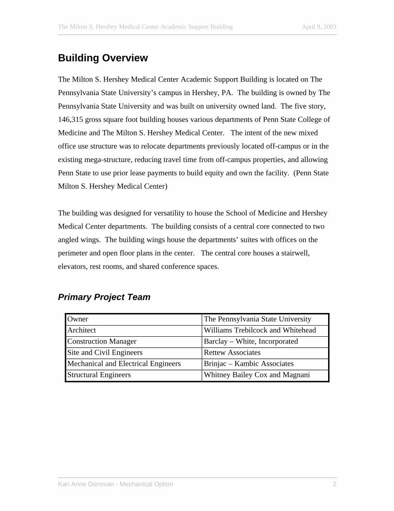
The building was designed for versatility to house the School of Medicine and Hershey
Medical Center departments. The building consists of a central core connected to two
angled wings. The building wings house the departments’ suites with offices on the
perimeter and open floor plans in the center. The central core houses a stairwell,
elevators, rest rooms, and shared conference spaces.
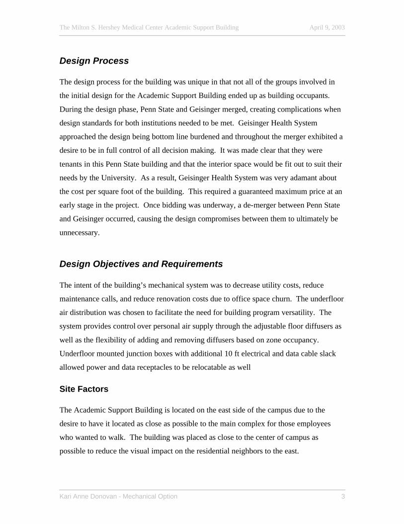
Primary Project Team
Owner The Pennsylvania State University Architect Williams Trebilcock and Whitehead Construction Manager Barclay – White, Incorporated Site and Civil Engineers Rettew Associates Mechanical and Electrical Engineers Brinjac – Kambic Associates Structural Engineers Whitney Bailey Cox and Magnani
The Milton S. Hershey Medical Center Academic Support Building April 9, 2003
Kari Anne Donovan - Mechanical Option 3
Design Process The design process for the building was unique in that not all of the groups involved in
the initial design for the Academic Support Building ended up as building occupants.
During the design phase, Penn State and Geisinger merged, creating complications when
design standards for both institutions needed to be met. Geisinger Health System
approached the design being bottom line burdened and throughout the merger exhibited a
desire to be in full control of all decision making. It was made clear that they were
tenants in this Penn State building and that the interior space would be fit out to suit their
needs by the University. As a result, Geisinger Health System was very adamant about
the cost per square foot of the building. This required a guaranteed maximum price at an
early stage in the project. Once bidding was underway, a de-merger between Penn State
and Geisinger occurred, causing the design compromises between them to ultimately be
unnecessary.
Design Objectives and Requirements The intent of the building’s mechanical system was to decrease utility costs, reduce
maintenance calls, and reduce renovation costs due to office space churn. The underfloor
air distribution was chosen to facilitate the need for building program versatility. The
system provides control over personal air supply through the adjustable floor diffusers as
well as the flexibility of adding and removing diffusers based on zone occupancy.
Underfloor mounted junction boxes with additional 10 ft electrical and data cable slack
allowed power and data receptacles to be relocatable as well
Site Factors The Academic Support Building is located on the east side of the campus due to the
desire to have it located as close as possible to the main complex for those employees
who wanted to walk. The building was placed as close to the center of campus as
possible to reduce the visual impact on the residential neighbors to the east.
The Milton S. Hershey Medical Center Academic Support Building April 9, 2003
Kari Anne Donovan - Mechanical Option 4
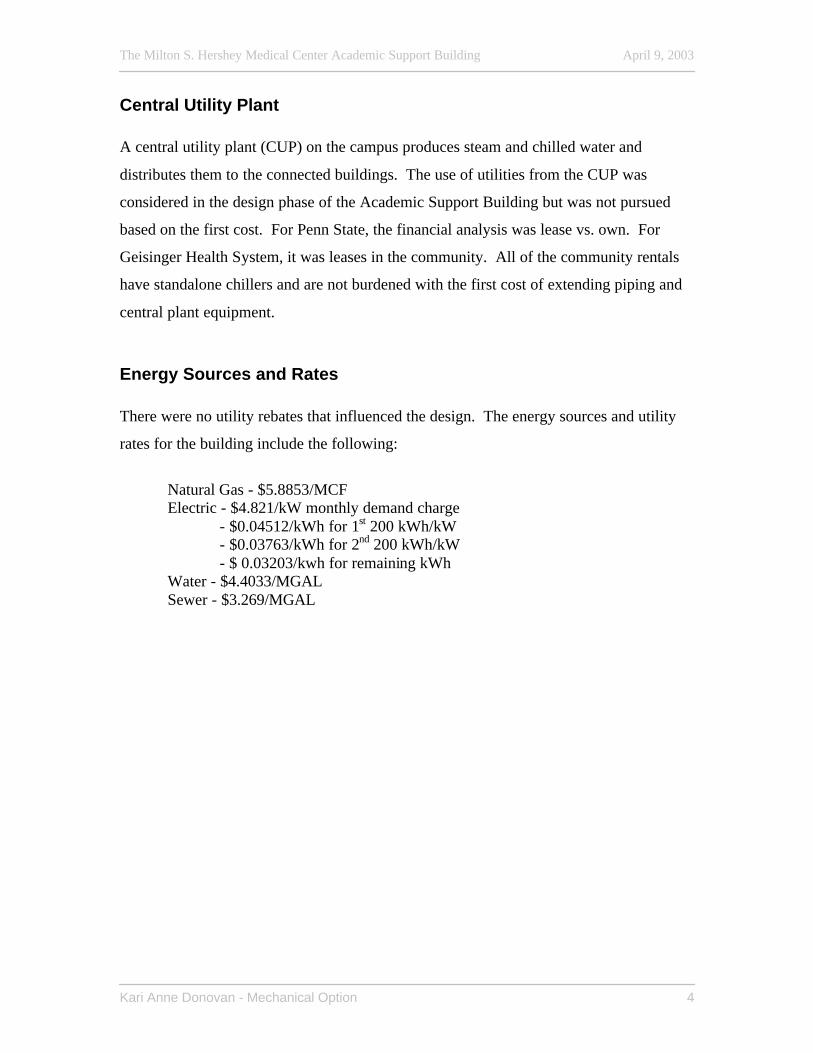
Central Utility Plant A central utility plant (CUP) on the campus produces steam and chilled water and
distributes them to the connected buildings. The use of utilities from the CUP was
considered in the design phase of the Academic Support Building but was not pursued
based on the first cost. For Penn State, the financial analysis was lease vs. own. For
Geisinger Health System, it was leases in the community. All of the community rentals
have standalone chillers and are not burdened with the first cost of extending piping and
central plant equipment.
Energy Sources and Rates There were no utility rebates that influenced the design. The energy sources and utility
rates for the building include the following:
Natural Gas - $5.8853/MCF Electric - $4.821/kW monthly demand charge
- $0.04512/kWh for 1st 200 kWh/kW - $0.03763/kWh for 2nd 200 kWh/kW - $ 0.03203/kwh for remaining kWh
Water - $4.4033/MGAL Sewer - $3.269/MGAL
The Milton S. Hershey Medical Center Academic Support Building April 9, 2003
Kari Anne Donovan - Mechanical Option 5
Construction Summary
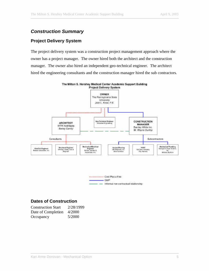
Project Delivery System The project delivery system was a construction project management approach where the
owner has a project manager. The owner hired both the architect and the construction
manager. The owner also hired an independent geo-technical engineer. The architect
hired the engineering consultants and the construction manager hired the sub contractors.
Dates of Construction Construction Start 2/28/1999 Date of Completion 4/2000 Occupancy 5/2000
The Milton S. Hershey Medical Center Academic Support Building April 9, 2003
Kari Anne Donovan - Mechanical Option 6
Cost Information
Division Estimate* Percent of Total General Requirements $991,146.00 5% Sitework $1,553,539.00 8% Concrete $1,850,000.00 10% Masonry $45,000.00 0% Metals $1,529,500.00 8% Wood and Plastics $451,250.00 2% Thermal and Moisture Protection $811,810.00 4% Doors and Windows $1,425,928.00 8% Finishes $1,292,359.00 7% Specialties $1,458,323.00 8% Equipment $- 0% Furnishings $595,770.00 3% Special Construction $- 0% Conveying Systems $160,000.00 1% Mechanical $2,864,835.00 15% Electrical $2,424,336.00 13% Contingency $850,000.00 4% Permits & Contractor Bonds $320,316.00 2% CM Fee $372,482.00 2% GMP $18,996,594.00 100%
* Figures from 2/19/1999 Revised GMP estimate prepared by Barclay White, Inc.
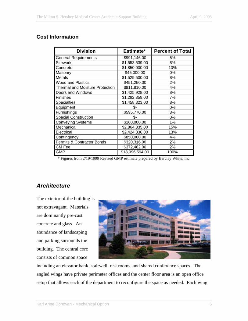
Architecture The exterior of the building is
not extravagant. Materials
are dominantly pre-cast
concrete and glass. An
abundance of landscaping
and parking surrounds the
building. The central core
consists of common space
including an elevator bank, stairwell, rest rooms, and shared conference spaces. The
angled wings have private perimeter offices and the center floor area is an open office
setup that allows each of the department to reconfigure the space as needed. Each wing
The Milton S. Hershey Medical Center Academic Support Building April 9, 2003
Kari Anne Donovan - Mechanical Option 7
also has a distinct entrance for each department. A staff eating area located on the first
floor is provided for the entire building. The mechanical penthouse is enclosed in high
quality painted metal.
Building Systems
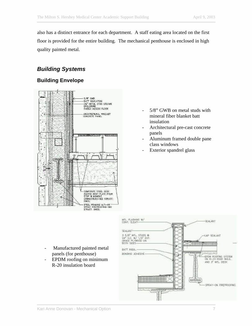
Building Envelope
- 5/8” GWB on metal studs with mineral fiber blanket batt insulation
- Architectural pre-cast concrete panels
- Aluminum framed double pane class windows
- Exterior spandrel glass
- Manufactured painted metal panels (for penthouse)
- EPDM roofing on minimum R-20 insulation board
The Milton S. Hershey Medical Center Academic Support Building April 9, 2003
Kari Anne Donovan - Mechanical Option 8
Electrical The electrical service to the building is supplied from the owner’s 15kV distribution
system in a concrete encased duct bank. Other building electrical components include
- Outdoor dual load break selector switches. - 15kVA transformer 13.8kV/480Y/277V. - Main distribution board 2500 amp, 480Y/277 main bus, metered. - 480 delta to 208Y/120 112.5kVA transformers on each floor - 150kW roof mounted generator set, 400 amp automatic transfer switch and
area protection panel. - Door security card reader system. - Video with room for future cameras and satellite dish for the roof. - Site Lighting control panel hand/off/auto integrated 365 day, 8-channel time
clock photocell. Time clock control and photocell control (auto/bypass) is in series for permitting site lighting.
Emergency Power The emergency power system includes a 480Y/277 3-phase 4-wire panel and a 208Y/120
3-phase panel for each floor. The building also has 2 emergency dry transformers, a
30kVA serving floors 1-3 and a 15kVA serving floors 4-5 and the penthouse. A
120/240V panel serves the food service/storage area. Power is provided by an emergency
generator that is activated by the emergency transfer switch.
Fire Alarm System The fire alarm system is an addressable multi-plex system designed to have 100% spare
capacity over designed points. It is listed for auxiliary and remote station service in
accordance with UL 860 – Control units for fire protective signaling service. The fire
alarm panel has an interface module to the main ATC panel, fire alarm annunciation
(120VAC normal emergency supply), manual pull stations, fire alarm visual signaling,
sprinkler system interface, and tamper switches on the control valves. Smoke detectors
are located in ducts and occupied areas. Elevator shafts have both heat and smoke
detectors while the cars only have heat detectors. The fire alarm panel is also tied into
the smoke proof enclosure systems.
The Milton S. Hershey Medical Center Academic Support Building April 9, 2003
Kari Anne Donovan - Mechanical Option 9
Lighting The outside lighting is 175W metal halide post-top lighting. Architectural area lighting is
compact fluorescent bollards. Spotlighting is achieved through flush mounted 75W
incandescent well lights. General interior lighting is compact fluorescent and F-32 T-8
277V with electronic ballasts, some with dimming capabilities. Exit signs are LED 277V
type. There is some specialty decorative lighting using incandescent lighting.
Underfloor Junction Boxes The underfloor junction boxes are mounted on the concrete floor and feed
flexible/detachable connectors to plug into relocateable floor boxes. The floor box
installation includes 2 duplex telephone/data jacks, 2 duplex outlets with a minimum of
10 ft of wiring slack to permit flexibility of location.
Telecommunications The telecommunications service to the building is fed from the site owned concrete
encased duct bank. The data cable trays are in the raised floor supply air plenum. There
is CAT 3 voice distribution in the main risers and CAT 5 for data distribution on the
floors. There is a minimum of 10 ft of CAT 5 wiring slack to permit the flexibility of the
location of the floor boxes.
Mechanical The building’s HVAC system is a variable air volume (VAV) underfloor air distribution
system. Automatic floor diffusers serve perimeter spaces and manual floor diffusers
serve interior spaces. Each floor has a ceiling plenum return with return air dampers
leading to the return airshaft and the return air plenum penthouse. Controls included in
the underfloor system are temperature, humidity, and pressure. The penthouse is a 7,513
sq ft return air plenum that also houses the air handling units, boilers, and pumps. There
are four 42,500 cfm supply air (3,750 cfm minimum outside air) air handling units
The Milton S. Hershey Medical Center Academic Support Building April 9, 2003
Kari Anne Donovan - Mechanical Option 10
(AHUs). The units have an outdoor air mixing box, 30% pre-filters, 90% filters, face and
bypass dampers for both the hot water heating coil and the chilled water cooling coil with
2 position, 2 way valves, and 400lb.hr gas fired humidifiers. Two units operate in an
AHU system to serve a wing. One of the system’s units has a variable frequency drive
(VFD). There are three gas fired boilers rated at 48.2 boiler hp and 1615 MBH. There is
a 27 ton winter reciprocating chiller with a remote chiller barrel and two 225 ton
packaged air cooled chillers. The primary chilled water pumps and the secondary hot
water pumps have VFD’s.
Four-pipe fan coil units serve the lobbies, vestibules, elevator waiting areas, electric
rooms, and data rooms. Hot water cabinet unit heaters serve the stairwells, penthouse,
and receiving rooms. Hot water radiant ceiling panels are located in the perimeter spaces
on all floors. Ceiling supply fans recirculate air from the ceiling return air plenum to the
occupied space in the conference rooms and workrooms.
Plumbing Gas lines are from the local utility provider. The owner owned metered water
distribution system with a back flow preventor and booster pumps feeds the entire
building. A 240 MBH gas fired water heater, with 100 gallon storage, serves the two
toilet banks on each floor. There is a water softener in the penthouse for the closed
chilled water loop. There are electric water coolers and an electric hot water heater.
There are 9kW, 277V no storage, instantaneous water heaters under remote floor sinks,
only cold water is supplied throughout the building floors aside from the toilet banks.
The gas fired water heater has a recirculating pump. The storm water, soil, waste, and
vent underground piping is hubless cast iron.
The Milton S. Hershey Medical Center Academic Support Building April 9, 2003
Kari Anne Donovan - Mechanical Option 11
Fire Protection The fire protection for the building was designed using the area density method. Wet
pipe automatic sprinkler systems exist throughout the building. The sprinkler heads are
UL listed and FM stamped. There is a flush type, wall-mounted fire department
connection and an inside/outside hose stream demand of 250 gpm. The system has a
double-detector-check backflow preventer. The fire alarm control panel is integrated to
the building fire alarm system through water flow switches (alarms) and supervisory
switches on valves. There is a valve control station on each floor.
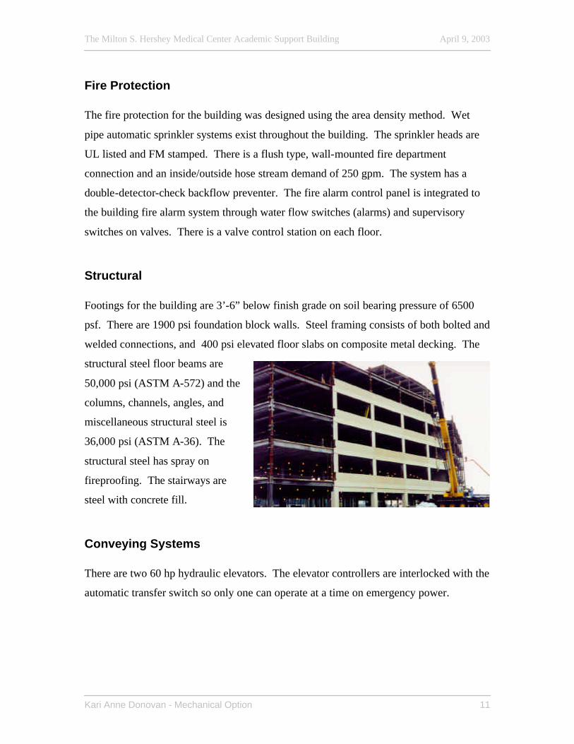
Structural Footings for the building are 3’-6” below finish grade on soil bearing pressure of 6500
psf. There are 1900 psi foundation block walls. Steel framing consists of both bolted and
welded connections, and 400 psi elevated floor slabs on composite metal decking. The
structural steel floor beams are
50,000 psi (ASTM A-572) and the
columns, channels, angles, and
miscellaneous structural steel is
36,000 psi (ASTM A-36). The
structural steel has spray on
fireproofing. The stairways are
steel with concrete fill.
Conveying Systems There are two 60 hp hydraulic elevators. The elevator controllers are interlocked with the
automatic transfer switch so only one can operate at a time on emergency power.
The Milton S. Hershey Medical Center Academic Support Building April 9, 2003
Kari Anne Donovan - Mechanical Option 12
Mechanical System - Existing
Existing System Schematics and Sequences of Operation
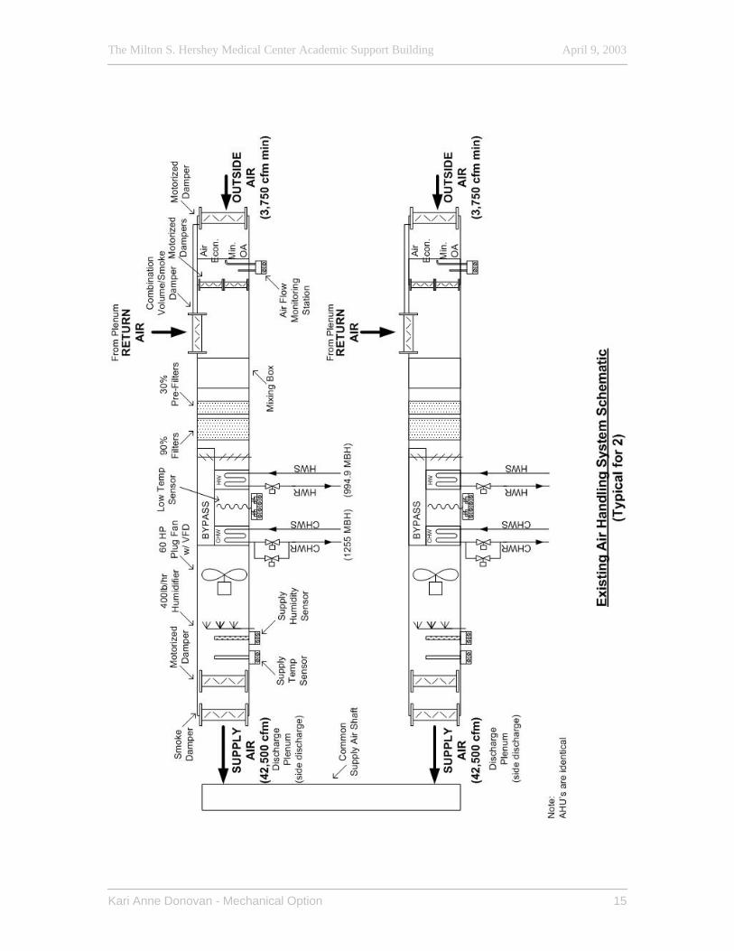
Air Handling System An air handling system is defined as two (2) variable volume AHUs in parallel serving a
common plenum, one (1) return air fan unit (with two parallel return air fans) with VFDs
and the capability of a 100% outside air economizer cycle. An air handling system serves
the east wing and a second air handling system serves the west wing of the building.
Safeties (Each AHU):
Smoke Detection – Smoke detectors located in the supply and return air ducts send a
signal to the fire alarm system when products of combustion are sensed. The fire alarm
system de-energizes the unit supply fans and closes the hard-wired isolation smoke
dampers. The direct digital control (DDC) controller closes the outside air dampers and
the alarm annunciates throughout the DDC system.
Freezestat – A low temperature cutout thermostat de-energizes the AHU when sensing a
temperature below 35oF and the alarm annunciates throughout the DDC system.
Overpressure Cutout – A high-pressure cutout switch de-energizes the AHU when the
sensed discharge pressure is above 6” W.C. and the alarm annunciates throughout the
DDC system.
Occupied Operation:
(The unit is run in occupied operation 6:00 AM to 6:00 PM, 7 days a week.)
Occupied Mode – On a signal from the DDC system, the AHUs and VFDs will sequence
in a heating or cooling mode as determined from the general office thermostats and the
dampers gradually open or close based on the thermostats’ signal to maintain setpoint.
On start-up, the minimum outdoor air dampers remain closed until the general office
thermostats reach their occupied setpoints (75oF summer/70oF winter). Once the
The Milton S. Hershey Medical Center Academic Support Building April 9, 2003
Kari Anne Donovan - Mechanical Option 13
setpoints are reached, the minimum outdoor air dampers modulate open to provide the
minimum outdoor air needed as determined by the airflow monitoring station.
Supply Air Volume Control – The VFD AHU for each AHU system is sequenced to
maintain the duct static pressure (2/3 of the way down the supply airshaft). The lead
VAV AHU VFD ramps up until the AHU approaches 100% airflow. If duct static
pressure is not reached, the lag AHU is energized and modulating the VFD’s equalizes
the airflow between the units. The DDC controller continuously sums the airflows.
When speeds are reduced in response to plenum pressure and total airflow decreases to a
value achievable by a single AHU, the lag unit stops and the isolation and minimum
outside air dampers close, and the VFD on the lead unit ramps up to meet the load.
Underfloor Air Plenum Control – A discharge damper located at each underfloor
distribution duct modulates to maintain the plenum pressure setpoint of 0.10” W.G. If
the general office temperature drops below the low limit setpoint of 68oF, then the
discharge dampers modulate close and override the pressure control.
Discharge Temperature Control – The face and by-pass dampers modulate o maintain
the discharge temperature setpoint (60oF cooling/90oF heating). On a call for cooling, the
chilled water valves open and the two-position heating valves shall open on a call for
heating. The heating and cooling valves will not open simultaneously.
Economizer – The system operates on integrated enthalpy control. When the outdoor
enthalpy is less than the return air enthalpy, the economizer (outside air) dampers
modulate with the return air dampers to maintain the AHU discharge temperature
setpoint. If the space relative humidity rises above 55% and the outdoor grains of
moisture is higher than the return air grains of moisture, then the economizer dampers
close and only minimum outside air is provided to the AHU.

The Milton S. Hershey Medical Center Academic Support Building April 9, 2003
Kari Anne Donovan - Mechanical Option 14
Humidification – The general office humidistats on each floor modulate the active
AHU’s humidifiers to maintain the space setpoint of 35% RH. A duct humidity sensor
insures supply duct humidity doesn’t exceed 85% RH.
Floor Plenum Sensors – Floor plenum temperature and humidity, and slab temperature
sensors are located at each floor for each AHU system. If the slab temperature
approaches within 3oF of the space temperature, the DDC system annunciates an alarm
and the AHU humidification setpoint is lowered.
Unoccupied Operation:
On a signal from the DDC, the AHU systems de-energize, the outside air dampers, floor
plenum discharge dampers, and relief air dampers close, and the return air dampers open.
When heat is needed, as determined by the general office thermostats, the supply air fan
cycles on until the setback conditions are met.
The Milton S. Hershey Medical Center Academic Support Building April 9, 2003
Kari Anne Donovan - Mechanical Option 15
The Milton S. Hershey Medical Center Academic Support Building April 9, 2003
Kari Anne Donovan - Mechanical Option 16
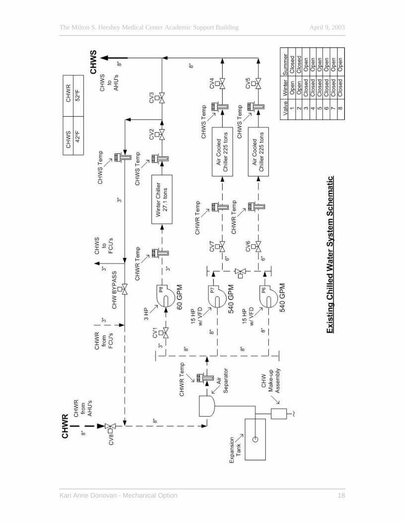
Chilled Water System The chilled water system is comprised of a two flow, primary loop piping system with
three air cooled chillers: two ‘summer’ chillers and one smaller chiller primarily for
‘winter’ use. The two ‘summer’ chillers operate in a lead/lag fashion when the outside
air temperature is above 60oF. The chillers are de-energized and the outside piping is
valved-off and drained-down during the ‘freezing’ season.
The ‘winter’ chiller with remote chiller barrel provides chilled water to the
telecommunications equipment room during the ‘air economizer’ season.
The chilled water flow quantity is varied as the ‘summer’ chillers are staged. Chilled
water pump VFDs maintain a constant water flow through their chillers as the secondary
system water flow varies. The ‘winter’ chiller energizes if the other chillers are unable to
maintain supply temperature setpoint.
There are no backup pumps for the chillers, but the pumps have been sized so that if a
‘summer’ pump fails, the remaining ‘summer’ pump can provide the minimum required
water flow to both chillers. This is not an automatic operation and requires manual
operation of valves.
Summer Mode – The DDC system energizes the chilled water system when the outside
air temperature rises above 60oF. The lead chiller pump energizes and ramps up to the
required speed. The AHUs first stage, two-position cooling coil valve opens to the coil.
Water flow is proven and the lead chiller energizes in stages to maintain chilled water
supply temperature setpoint of 42oF. If the lead chiller is unable to maintain setpoint, the
lag chiller is energized in the same sequence. The AHUs second stage, two-position
cooling coil valve opens to the coil if additional chilled water is required. If both chillers
are unable to maintain setpoint, the ‘winter’ chiller pump energizes and the DDC system
annunciates an alarm.
The Milton S. Hershey Medical Center Academic Support Building April 9, 2003
Kari Anne Donovan - Mechanical Option 17
Winter Mode – The ‘winter’ chiller pump energizes and runs continuously. When water
flow is proven, the ‘winter’ chiller is energized in stages to maintain chilled water supply
temperature setpoint of 42oF. The pressure by-pass valve modulates to maintain chilled
water flow and prevents dead-heading. A high temperature alarm is generated if the
space temperature rises above 90oF.
The Milton S. Hershey Medical Center Academic Support Building April 9, 2003
Kari Anne Donovan - Mechanical Option 18
The Milton S. Hershey Medical Center Academic Support Building April 9, 2003
Kari Anne Donovan - Mechanical Option 19
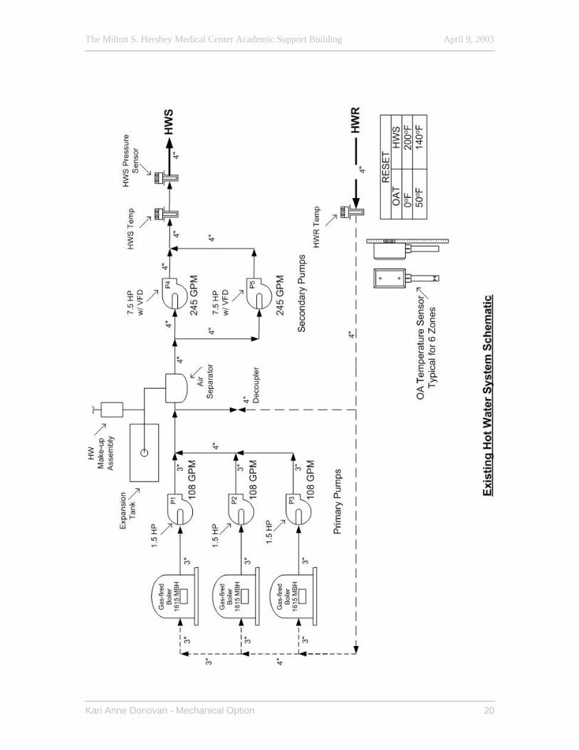
Hot Water System Three gas-fired boilers are controlled by the DDC system to supply the building heating
primary/secondary loop system. The hot water system is automatically indexed from the
outside air temperature, and incorporates a reset schedule that resets the hot water
temperature setpoint. If the lead boiler is unable to maintain temperature setpoint, then
the remaining boilers and pumps will energize in the same sequence to maintain setpoint.
Secondary Hot Water Pumps – The lead pump is started by the DDC controller with
the outside air temperature is less than 50oF. The lead pump is alternated monthly to
equalize the run times. The pump VFD modulates the pump speed to maintain secondary
loop pressure setpoint.
Primary Hot Water Pumps – The lead primary pump energizes, the combustion air
intake damper opens, and the boiler energizes once water flow is proven to maintain
secondary hot water temperature setpoint. Alarms will be sent throughout the DDC
system if a pump fails to operate after a 5 second delay.
The Milton S. Hershey Medical Center Academic Support Building April 9, 2003
Kari Anne Donovan - Mechanical Option 20
The Milton S. Hershey Medical Center Academic Support Building April 9, 2003
Kari Anne Donovan - Mechanical Option 21
Existing System Critique and Operating History The building’s VAV underfloor air distribution system is still unique in office buildings
when compared to the more traditional ceiling VAV supply system. The omission of a
return air fan system and the placement of the gas-fired equipment in the negatively
pressured return air plenum penthouse were intriguing. The gas-fired humidifiers have
been changed to electric and the gas-fired boilers were reconfigured to allow them to
operate properly. The building owner representatives mentioned watching water gurgling
out of the drains and onto the floor in the plenum because of the negative pressure in the
space.
A return fan system has been added within the past year, placing the return fans in the
airshafts and ducting the shafts to the AHUs. The addition of the ductwork removed the
penthouse from the air stream, thus eliminating the negative pressure problem. The
airshafts have a common wall with conference and meeting rooms on several floors. The
noise from the new fans was so great that conversations could not be heard from one end
of a 10 ft table to the other. Additional steps had to be taken to dampen the fan noise.
The building occupants have registered many complaints about the thermal comfort of
the building. After a year of occupancy, half a million dollars was spent to attempt to
resolve the performance of the mechanical system. Reheat had to be added to the first
floor because the floor was concrete slab-on-grade in direct contact with the underfloor
supply air plenum and the supply air temperature was too low. Humidity control in the
spaces was also a problem; at one point, paychecks couldn’t be printed because of the
conditions. Other issues that had to be addressed after occupancy were related to noise
and building envelope leakage. The chillers are not located on the structural concrete
slab that the remaining mechanical equipment inside the penthouse is. They are placed
on an isolated concrete island on the membrane roof at the center of each wing. As a
result, high frequency compressor noise and vibration noise were a problem for the
tenants on the fifth floor.
The Milton S. Hershey Medical Center Academic Support Building April 9, 2003
Kari Anne Donovan - Mechanical Option 22
The existing mechanical system does not comply with minimum outdoor air requirements
described in ASHRAE Standard 62. The design was not required by the owner to meet
ASHRAE Standard 62 at the time. Building occupants have a great deal of personal
control over the placement of diffusers in their spaces by relocating the floor diffusers or
covering them up with magazines, further reducing the ventilation air in some spaces.
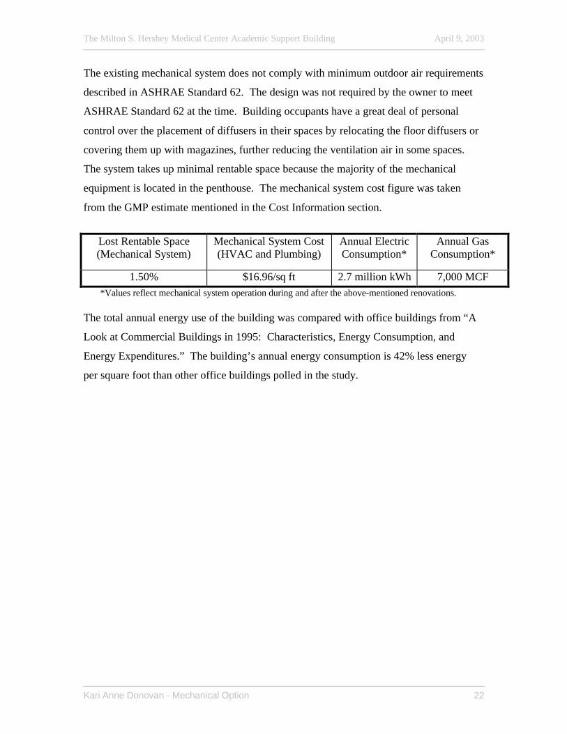
The system takes up minimal rentable space because the majority of the mechanical
equipment is located in the penthouse. The mechanical system cost figure was taken
from the GMP estimate mentioned in the Cost Information section.
Lost Rentable Space (Mechanical System)
Mechanical System Cost (HVAC and Plumbing)
Annual Electric Consumption*
Annual Gas Consumption*
1.50% $16.96/sq ft 2.7 million kWh 7,000 MCF *Values reflect mechanical system operation during and after the above-mentioned renovations.
The total annual energy use of the building was compared with office buildings from “A
Look at Commercial Buildings in 1995: Characteristics, Energy Consumption, and
Energy Expenditures.” The building’s annual energy consumption is 42% less energy
per square foot than other office buildings polled in the study.
The Milton S. Hershey Medical Center Academic Support Building April 9, 2003
Kari Anne Donovan - Mechanical Option 23
Mechanical System – Redesign The less than desirable general performance of the mechanical system has already caused
the system to be modified as previously mentioned. The basis of the building analysis
thus far has been from the as-built drawings supplied by the building owner. These
drawings represent the system as it was during building occupancy in May 2000 and is
the basis for the new construction redesign, not a retrofit redesign. The redesign will also
be conducted under the assumption that the constraints due to the Penn State and
Geisinger merger were lifted prior to design. Specific redesign goals include:
- Improved thermal comfort and humidity control - Improved indoor air quality (IAQ) by system compliance with ASHRAE
Standard 62 - Reduced energy costs - Reduced 1st cost - Meet the criteria of building program
These areas will be addressed with the intention of better performance without drastically
elevated construction, operating, and 1st costs compared to the system operation depicted
on the as-built drawings.
Distributed Chilled Water Feasibility Study (AE Depth)
District Utilities District energy systems produce steam, hot water, or chilled water at a central plant.
These utilities are then delivered to buildings via piping networks for space heating,
domestic hot water heating, and air conditioning. Buildings that receive utilities from a
central plant do not need their own boilers, furnaces, or chillers, or the space to contain
them. Benefits of central plant systems over similar standalone systems include lower
life cycle costs, increased design and operation flexibility, and increased energy
efficiency.
The lower life cycle costs are a result of a reduction in building upfront costs as well as
operation, maintenance, and labor costs. If boilers, furnaces, and chillers are not a part of
The Milton S. Hershey Medical Center Academic Support Building April 9, 2003
Kari Anne Donovan - Mechanical Option 24
the building, there will be a lower building project capital cost leading to lower principal
and interest payments and annual maintenance contracts. Because the more sizeable
mechanical equipment is not in the building, there is a decrease in lost rentable space due
to mechanical equipment in the building.
The greater design flexibility is due to the exclusion of designing for boilers, cooling
towers, and other mechanical equipment within the building project. This allows for a
more aesthetically pleasing building for the occupants, including less noise production
from the mechanical system. The plant has more operating flexibility than a standalone
mechanical system because it can take advantage of using a variety of fuels including
coal, oil, and natural gas. The plant can use whichever is the most cost effective at the
time whereas a standalone system is limited to the system design fuel and is ultimately at
the mercy of the energy market.
Because of a utility plant’s larger size, it can more easily take advantage of the use of
renewable fuels including biomass, geothermal, and incorporate combined heat and
power strategies. The utilities that are distributed arrive at the connected buildings ready
to use, meaning 100% efficient. If the same utilities are produced in a standalone system,
there is an efficiency of 80% or lower for natural gas or fuel oil. This increased
combined heat and power utility plant production efficiency exists because the rejected
heat of burning fuels can be utilized at the plant to generate electricity or power other
equipment. Utility plants can also use higher efficiency chillers and boilers because of
the increased size of the equipment than what would be contained in a separate
standalone system. Utility plants are also more reliable than what would be contained in
a separate standalone system. Utility plants are also more reliable than standalone
systems because of around-the-clock operators and well-defined backup systems.
District cooling plants displace peak electrical power demand with steam-based cooling,
district cooling, and thermal energy storage. District cooling plants can generally be
designed to meet a load that is less than the sum of the connected peak loads because of
load diversity effects. Different building loads that are connected to a single district
The Milton S. Hershey Medical Center Academic Support Building April 9, 2003
Kari Anne Donovan - Mechanical Option 25
cooling plant can peak out of phase. It is therefore possible to provide reliable cooling
capacity to a collection of buildings having installed a fraction of the peak capacity
required at each building in a standalone system. A district cooling plant also provides a
greater degree of redundancy than what is usually found in standalone systems. When
thermal energy storage (TES) is added to a district cooling plant, the plant is better able
to accomplish load shift. A load leveling chilled water thermal storage tank can be
discharged during the peak load instead of bringing another machine online to meet the
increase in load. This provides energy cost savings because peak loads generally occur
during the same time of day when energy rates are the highest. Once the load decreases
to where the online machines can meet it, the thermal storage tank is once again placed in
charge mode.
Strategic planning is required for district energy systems. The plant capacity and space
for additional equipment must be estimated and implemented prior to both short and long
term anticipated needs. Decisions based on energy sources and refrigerant types must be
addressed in capital and master planning sessions on the basis of budget and expected
energy costs; overall, a very complex process.
The Milton S. Hershey Medical Center Academic Support Building April 9, 2003
Kari Anne Donovan - Mechanical Option 26
Central Utility Plant (Refer to Distributed Utilities Map – Appendix A)
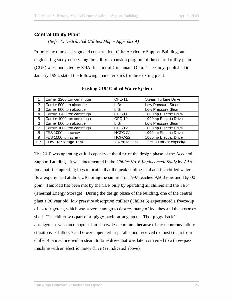
Prior to the time of design and construction of the Academic Support Building, an
engineering study concerning the utility expansion program of the central utility plant
(CUP) was conducted by ZBA, Inc. out of Cincinnati, Ohio. The study, published in
January 1998, stated the following characteristics for the existing plant.
Existing CUP Chilled Water System
1 Carrier 1200 ton centrifugal CFC-11 Steam Turbine Drive 2 Carrier 800 ton absorber LiBr Low Pressure Steam 3 Carrier 800 ton absorber LiBr Low Pressure Steam 4 Carrier 1200 ton centrifugal CFC-11 1000 hp Electric Drive 5 Carrier 1000 ton centrifugal CFC-12 1000 hp Electric Drive 6 Carrier 800 ton absorber LiBr Low Pressure Steam 7 Carrier 1000 ton centrifugal CFC-12 1000 hp Electric Drive 8 FES 1000 ton screw HCFC-22 1000 hp Electric Drive 9 FES 1000 ton screw HCFC-22 1000 hp Electric Drive
TES CHWTR Storage Tank 1.4 million gal 12,5000 ton-hr capacity
The CUP was operating at full capacity at the time of the design phase of the Academic
Support Building. It was documented in the Chiller No. 6 Replacement Study by ZBA,
Inc. that ‘the operating logs indicated that the peak cooling load and the chilled water
flow experienced at the CUP during the summer of 1997 reached 9,500 tons and 16,000
gpm. This load has been met by the CUP only by operating all chillers and the TES’
(Thermal Energy Storage). During the design phase of the building, one of the central
plant’s 30 year old, low pressure absorption chillers (Chiller 6) experienced a freeze-up
of its refrigerant, which was severe enough to destroy many of its tubes and the absorber
shell. The chiller was part of a ‘piggy-back’ arrangement. The ‘piggy-back’
arrangement was once popular but is now less common because of the numerous failure
situations. Chillers 5 and 6 were operated in parallel and received exhaust steam from
chiller 4, a machine with a steam turbine drive that was later converted to a three-pass
machine with an electric motor drive (as indicated above).
The Milton S. Hershey Medical Center Academic Support Building April 9, 2003
Kari Anne Donovan - Mechanical Option 27
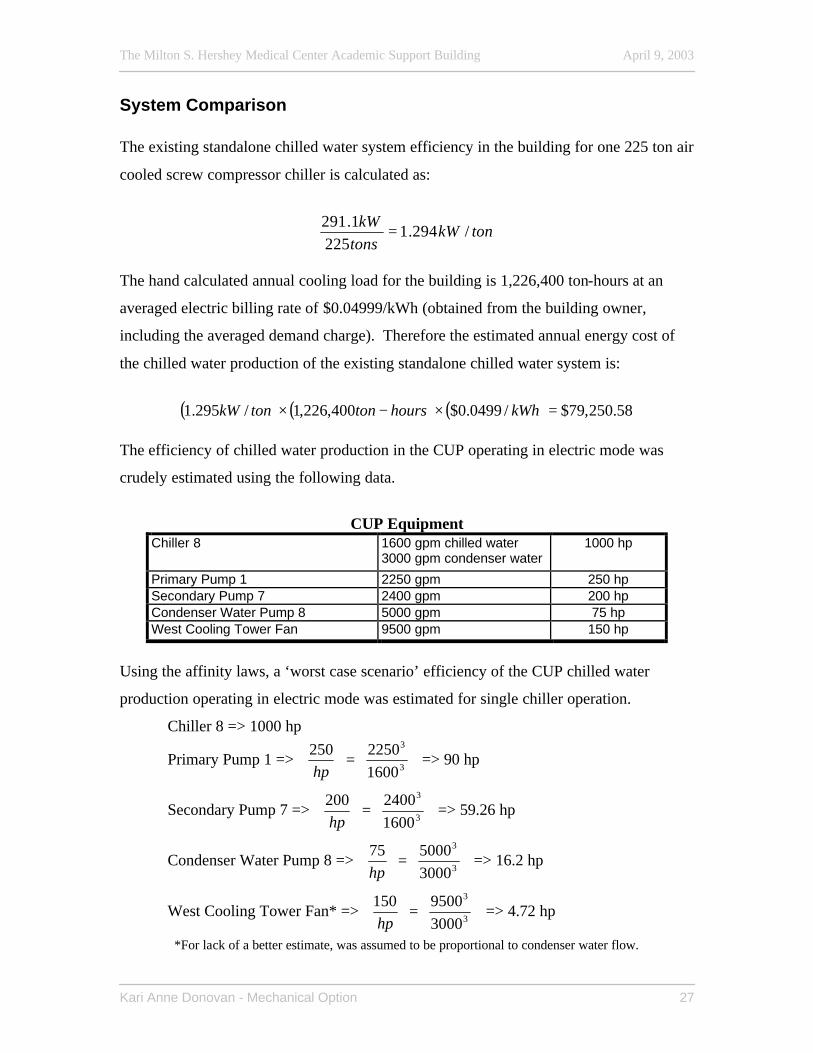
System Comparison The existing standalone chilled water system efficiency in the building for one 225 ton air
cooled screw compressor chiller is calculated as:
tonkWtons
kW/294.1
2251.291 =
The hand calculated annual cooling load for the building is 1,226,400 ton-hours at an
averaged electric billing rate of $0.04999/kWh (obtained from the building owner,
including the averaged demand charge). Therefore the estimated annual energy cost of
the chilled water production of the existing standalone chilled water system is:
( ) ( ) ( ) 58.250,79$/0499.0$400,226,1/295.1 =×−× kWhhourstontonkW
The efficiency of chilled water production in the CUP operating in electric mode was
crudely estimated using the following data.
CUP Equipment
Chiller 8 1600 gpm chilled water 3000 gpm condenser water
1000 hp
Primary Pump 1 2250 gpm 250 hp Secondary Pump 7 2400 gpm 200 hp Condenser Water Pump 8 5000 gpm 75 hp West Cooling Tower Fan 9500 gpm 150 hp
Using the affinity laws, a ‘worst case scenario’ efficiency of the CUP chilled water
production operating in electric mode was estimated for single chiller operation.
Chiller 8 => 1000 hp
Primary Pump 1 =>
=
3
3
16002250250
hp => 90 hp
Secondary Pump 7 =>
=
3
3
16002400200
hp => 59.26 hp
Condenser Water Pump 8 =>
=
3
3
3000500075
hp => 16.2 hp
West Cooling Tower Fan* =>
=
3
3
30009500150
hp => 4.72 hp
*For lack of a better estimate, was assumed to be proportional to condenser water flow.
The Milton S. Hershey Medical Center Academic Support Building April 9, 2003
Kari Anne Donovan - Mechanical Option 28
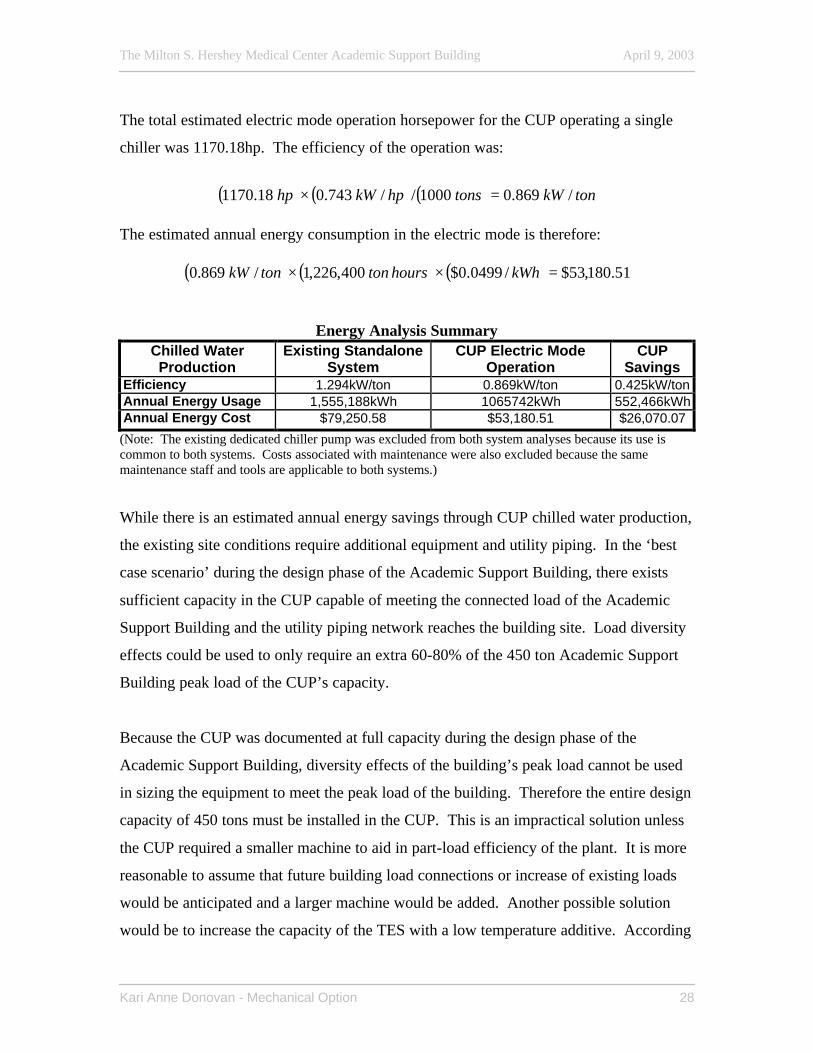
The total estimated electric mode operation horsepower for the CUP operating a single
chiller was 1170.18hp. The efficiency of the operation was:
( ) ( ) ( ) tonkWtonshpkWhp /869.01000//743.018.1170 =×
The estimated annual energy consumption in the electric mode is therefore:
( ) ( ) ( ) 51.180,53$/0499.0$400,226,1/869.0 =×× kWhhourstontonkW
Energy Analysis Summary
Chilled Water Production
Existing Standalone System
CUP Electric Mode Operation
CUP Savings
Efficiency 1.294kW/ton 0.869kW/ton 0.425kW/ton Annual Energy Usage 1,555,188kWh 1065742kWh 552,466kWh Annual Energy Cost $79,250.58 $53,180.51 $26,070.07
(Note: The existing dedicated chiller pump was excluded from both system analyses because its use is common to both systems. Costs associated with maintenance were also excluded because the same maintenance staff and tools are applicable to both systems.) While there is an estimated annual energy savings through CUP chilled water production,
the existing site conditions require additional equipment and utility piping. In the ‘best
case scenario’ during the design phase of the Academic Support Building, there exists
sufficient capacity in the CUP capable of meeting the connected load of the Academic
Support Building and the utility piping network reaches the building site. Load diversity
effects could be used to only require an extra 60-80% of the 450 ton Academic Support
Building peak load of the CUP’s capacity.
Because the CUP was documented at full capacity during the design phase of the
Academic Support Building, diversity effects of the building’s peak load cannot be used
in sizing the equipment to meet the peak load of the building. Therefore the entire design
capacity of 450 tons must be installed in the CUP. This is an impractical solution unless
the CUP required a smaller machine to aid in part-load efficiency of the plant. It is more
reasonable to assume that future building load connections or increase of existing loads
would be anticipated and a larger machine would be added. Another possible solution
would be to increase the capacity of the TES with a low temperature additive. According
The Milton S. Hershey Medical Center Academic Support Building April 9, 2003
Kari Anne Donovan - Mechanical Option 29
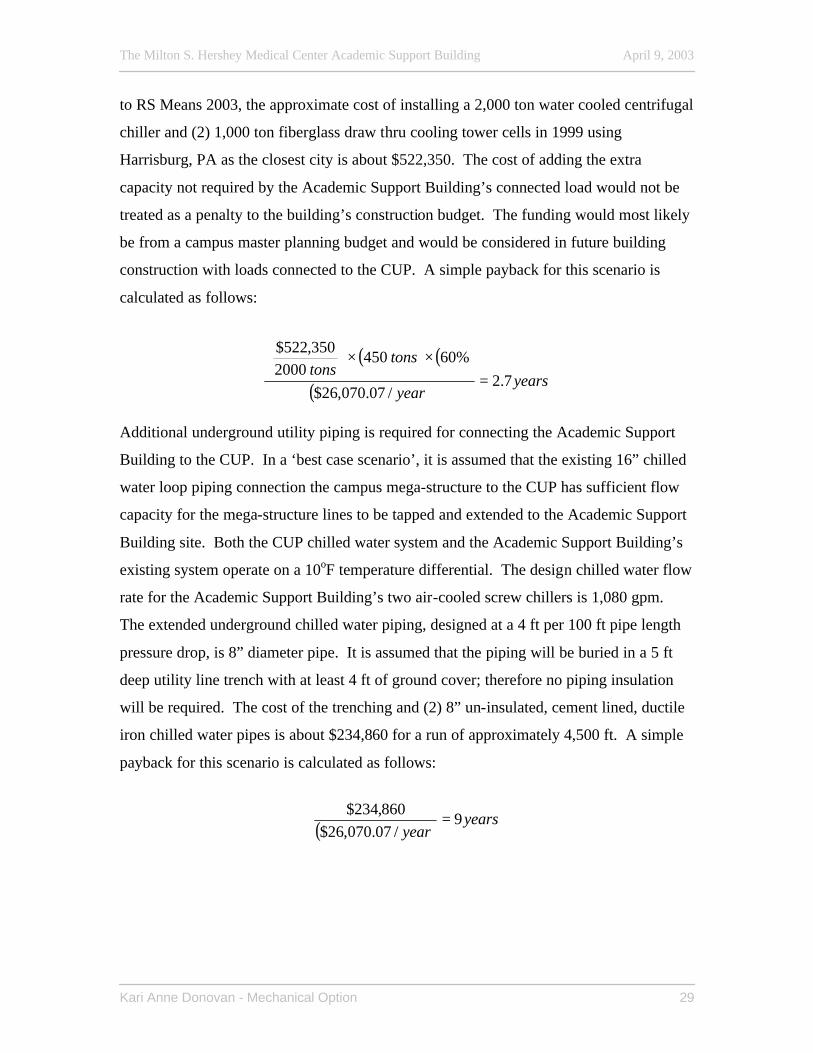
to RS Means 2003, the approximate cost of installing a 2,000 ton water cooled centrifugal
chiller and (2) 1,000 ton fiberglass draw thru cooling tower cells in 1999 using
Harrisburg, PA as the closest city is about $522,350. The cost of adding the extra
capacity not required by the Academic Support Building’s connected load would not be
treated as a penalty to the building’s construction budget. The funding would most likely
be from a campus master planning budget and would be considered in future building
construction with loads connected to the CUP. A simple payback for this scenario is
calculated as follows:
( ) ( )
( ) yearsyear
tonstons
7.2/07.070,26$
%604502000
350,522$
=××
Additional underground utility piping is required for connecting the Academic Support
Building to the CUP. In a ‘best case scenario’, it is assumed that the existing 16” chilled
water loop piping connection the campus mega-structure to the CUP has sufficient flow
capacity for the mega-structure lines to be tapped and extended to the Academic Support
Building site. Both the CUP chilled water system and the Academic Support Building’s
existing system operate on a 10oF temperature differential. The design chilled water flow
rate for the Academic Support Building’s two air-cooled screw chillers is 1,080 gpm.
The extended underground chilled water piping, designed at a 4 ft per 100 ft pipe length
pressure drop, is 8” diameter pipe. It is assumed that the piping will be buried in a 5 ft
deep utility line trench with at least 4 ft of ground cover; therefore no piping insulation
will be required. The cost of the trenching and (2) 8” un-insulated, cement lined, ductile
iron chilled water pipes is about $234,860 for a run of approximately 4,500 ft. A simple
payback for this scenario is calculated as follows:
( ) yearsyear
9/07.070,26$
860,234$=
The Milton S. Hershey Medical Center Academic Support Building April 9, 2003
Kari Anne Donovan - Mechanical Option 30
Conclusion The benefits of district energy systems make them an attractive alternative to individual
building standalone systems, especially for a privately owned campus of buildings like
the Penn State College of Medicine. The reduced kW/ton of the CUP provides not only
increased efficiency and therefore energy savings, but it also reduces the campus electric
demand charge. In addition to energy savings, there are operation and maintenance
savings that are more difficult to evaluate. The energy savings provided in this example
do not appear to outweigh the added cost of increasing the plant size and extending utility
lines, but it must be understood that the costs presented do not reflect the additional cost
to the building project. Only a portion of the burden will be felt by the building
construction budget and the rest will be paid for by the campus master plan and utility
expansion budgets. For the specific case study of the Academic Support Building, it is
clear that situational factors during the design phase of the building, including its remote
location, no immediate plans for nearby construction, and a CUP already at capacity did
not allow for its connection to the CUP. There is currently a proposal up for review to
add a second utility loop from the CUP south of the mega-structure to reach future
construction on the east side of the campus, however possible implementation of that
proposal is still at least five years away. A satellite CUP on the east end of campus is
also a possibility, however such plants are generally located further apart.
Dedicated Outdoor Air System/Radiant Cooling Panel System (AE Depth)
Introduction Traditional all-air variable-air volume (VAV) systems mix a portion of return air with
outdoor air at the air handling unit (AHU). The proper distribution of this air is a
function of VAV box minimum settings, space sensible loads, local exhaust and
exfiltration, short circuiting paths, and interzonal air transfer (Mumma, Lee 1998).
Understanding where all of the ventilation air terminates is not possible. A dedicated
The Milton S. Hershey Medical Center Academic Support Building April 9, 2003
Kari Anne Donovan - Mechanical Option 31
outdoor air system supplies 100% outdoor air to the space, ensuring that a design in
compliance with ASHRAE Standard 62 ventilation requirements will deliver the design
ventilation air to the correct spaces. When only a portion of the supply air is ventilation
air, some spaces are over ventilated due to the multiple spaces equation of ASHRAE
Standard 62. With a dedicated outdoor air system, the introduction of excess outdoor air
is greatly reduced and therefore reduces the amount of energy required for outdoor air
conditioning.
Dedicated outdoor air systems provide improved humidity control by conditioning the
primary source of humidity in the building; outdoor air. Properly controlling humidity
levels in the conditioned space can prevent mold growth and improve indoor air quality.
The outdoor air meets the latent load in the space as well as a portion of the sensible load.
A parallel sensible system can then be run at higher cooling temperatures that improve
energy efficiency (DOE-1999). There is extra energy expended in conventional systems
where only a portion of the supply air (SA) is outdoor air to condition both the return air
(RA) from the space and the outdoor air.
The use of radiant cooling panels as the sensible system in parallel with the DOAS has
many aspects. Chilled water flows through pipes on the upper surface of the radiant
panel and cools the space through natural convection and radiative heat transfer. While
this technology is common in Europe, it is not widely applied in the United States. A
major sticking point in industry is the possible formation of condensation on the panels,
potentially leading to damaged ceiling materials and possible biological growth. For
radiant cooling panels to be applied, proper humidity control and tight building envelopes
are necessary. For this reason, coupling the radiant cooling panel system and a DOAS
system is a natural union because of the DOAS’s superior humidity control. With the
chilled water supply temperature to the panels several degrees above the design space
dewpoint temperature, condensation formation on the panels should not be an issue.
Condensation sensors can be applied to vertical runs on the supply side to detect
condensation, and supply pipes in unconditioned and critical spaces should be insulated.
The Milton S. Hershey Medical Center Academic Support Building April 9, 2003
Kari Anne Donovan - Mechanical Option 32
Radiant cooling panel systems should only be considered if there is a parallel system used
to de-couple the space sensible and latent loads.
The use of an energy recovery wheel was also explored. ASHRAE Standard 90.1-1999
section 6.3.6.1 refers to exhaust air energy recovery in systems with a design outside air
supply of 70% or greater than the total supply air volume and a design supply air volume
of 5,000 cfm. Such a system must have an energy recovery unit with at least 50%
recovery effectiveness. Using a total energy recovery wheel has the potential to reduce
required heating and cooling equipment capacities. Energy recovery between exhaust
and supply air can reduce peak cooling and heating load to condition the outdoor air as
well as the plant equipment size needed. The added installation cost of an energy
recovery wheel is most often the reason their application in design suffers. Often,
designers do not take credit for the reduction in the heating and cooling plant to offset the
first cost of an energy recovery wheel, thus making its addition to the system more costly
than it is. Other reasons they may not be used include increased maintenance, possible
frosting, and increased fan power requirements.
Replacing an all air system with a parallel air-water system would appear to have a
higher installation cost because of the additional equipment for the two systems. The
reality is that there is potential installation cost savings in implementing a DOAS/radiant
system. The radiant panels do contribute to the installation cost of the system, but there
are still areas for potential savings. The major items are addressed below (Mumma,
2001):
- Chiller size reduction (result of less OA and Energy Recovery) - Reduced pump size (result of chiller reduction) - Reduced ductwork installation cost (result of less SA) - Reduced plenum depth; envelope materials, building height (result of
less SA) - Air handling unit size reduction - Electrical service to mechanical equipment reduction - Piping reduction (integration of fire suppression system) - Acoustical ceiling panel reduction (where replaced with radiant
panels) - Less lost rentable space due to mechanical shaft needed for SA and
RA ductwork
The Milton S. Hershey Medical Center Academic Support Building April 9, 2003
Kari Anne Donovan - Mechanical Option 33
Through the reduction of equipment sizes and improved chiller COP, there is a potential
energy savings. Modeling this is more difficult than perceived. Conventional modeling
software does not simply and effectively model a DOAS/radiant system. A new software
package would increase the ability of HVAC designers to design and sell such a system
to clients.
System Redesign The dedicated outdoor air system (DOAS) was designed to deliver 20 cfm/person to the
building via high aspiration diffusers located in the suspended ceiling. The occupancy
rate was determined by the larger of the Architect’s design occupancy for the building
and the ASHRAE Standard 62 section 6.3.1 design occupancy. For the conference rooms
and the perimeter office spaces, the larger of the two occupancies was given by ASHRAE
Standard 62. ASHRAE Standard 90.1-1999 section 6.3.2.1 discusses conditions where
simultaneous heating and cooling is allowable. Included is when the volume of air that is
reheated is no larger than the volume of air required to meet the ventilation requirements
defined in ASHRAE Standard 62 section 6.3.1.
There are several types of outdoor treatment and ventilation systems. The two pursued in
this study are outdoor air delivered to the space and outdoor air delivered to a terminal
unit. The building wing floor plan is divided into three zones for each wing; 1 - north
facing private perimeter offices, 2 - central open offices with minimal glazing, and 3 -
south facing private perimeter offices. Conditioned air is supplied from the wing’s AHU
to all zone ductwork at a common supply air temperature of 45oF in both the heating and
cooling season. The central offices have a year round cooling load because there is
minimal envelope load, if any. These spaces are supplied with conditioned outdoor air
directly to the space from the AHU. The private perimeter office spaces are supplied
with conditioned outdoor air through a terminal reheat coil at each floor to handle the
heating loss through the glazing in the heating season. Zones 1 and 3 have separate
terminal reheat coils to accommodate for the difference in solar loads on opposite sides of
The Milton S. Hershey Medical Center Academic Support Building April 9, 2003
Kari Anne Donovan - Mechanical Option 34
the building. Conference rooms and work rooms with variable and more dense
occupancies are supplied via Zone 2 with terminal reheat VAV boxes with CO2 sensors
to control the volume.
The room conditions were modeled in HAP4.1b to determine the building loads. The
loads were then de-coupled to determine the sensible and latent cooling done by the
DOAS. The remaining sensible load left in the space determined the pendant mounted
radiant cooling panel area. Redec’s radiant panel sizing software was used to size the
panels. A typical section was modeled for 3 panels connected in series to determine
capacity, pressure drop, and flow characteristics. Lay-in hot water radiant heating panels
were sized similarly, after taking into account the reheat temperature provided in Zones 1
and 3.
(Refer to Mechanical Depth Calculations – Appendix C)
(Refer to Equipment Cut Sheets – Appendix D)
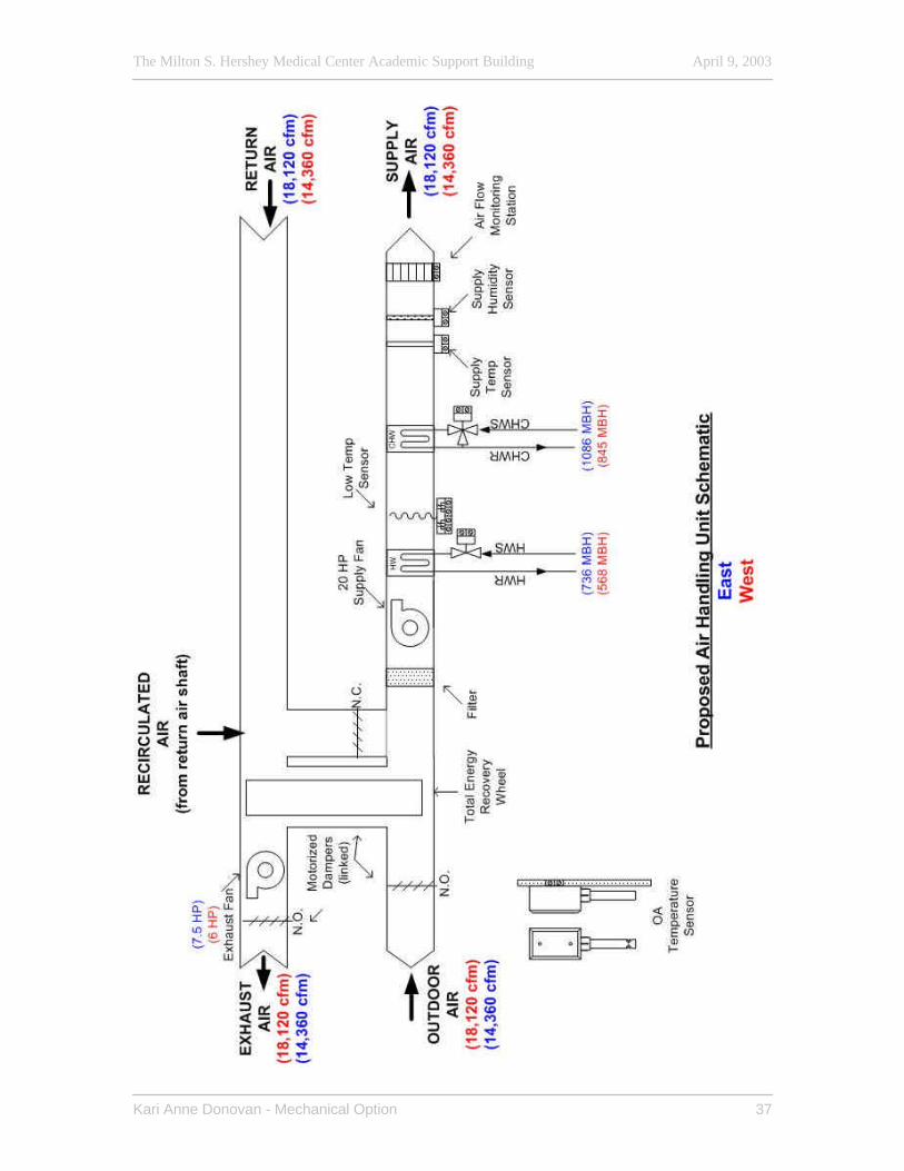
AHU Sequence of Operation Air Handling Units: There are two air handling units for the Dedicated Outdoor Air System (DOAS).
One serves each wing of the building.
Safeties (Each AHU):
Smoke Detection – Smoke detectors are located in the supply and return air ducts send a
signal to the fire alarm system when products of combustion are sensed. The fire alarm
system de-energizes the unit supply fan and closes the hard-wired isolation smoke
dampers. The DDC controller closes the outside air dampers and the alarm annunciates
throughout the DDC system.
Freezestat – A low temperature cutout thermostat de-energizes the AHU when sensing a
temperature below 35oF and the alarm annunciates throughout the DDC system.
The Milton S. Hershey Medical Center Academic Support Building April 9, 2003
Kari Anne Donovan - Mechanical Option 35
Occupied Operation: (The unit is run in occupied operation 5:00 AM to 6:00 PM, 7 days a week.)
Occupied Mode – On a signal from the Direct Digital Control (DDC) system, the AHUs
will sequence in a heating or cooling mode as determined from the general office
thermostats. On start-up, the outdoor and exhaust air dampers remain closed and the
mixed air dampers are open. The building air is recirculated by the constant speed supply
air fan until the general office thermostats reach the occupied dry bulb setpoint (75oF
summer/70oF winter). Once the space dry bulb setpoint is reached, the outdoor and
exhaust air dampers open and the mixed air damper closes to provide 100% outdoor air to
ventilate the building. The exhaust fan is energized when the exhaust air dampers open.
The supply air temperature is maintained at 45oF. When the outdoor air temperature is
less than the supply air temperature, the heating coil valve modulates open to maintain
45oF supply air temperature. When the outdoor air temperature is greater than the supply
air temperature, the cooling coil valve modulates open to maintain 45oF supply air
temperature. The heating and cooling valves will never be open simultaneously. On a
call for heating in the perimeter zones by space thermostats, the heating valves on the
reheat coils will modulate open to meet space temperature setpoint (detailed in Typical
Floor Sequence of Operation).
Supply Air Volume Control for Conference Rooms – The conference rooms will be
conditioned via variable air volume (VAV) boxes at 45oF. On a signal from a conference
room CO2 sensor relaying to the DDC system that a conference room is occupied, the
space VAV box will modulate to full open to allow 100% ventilation air to the space. On
a call for heating from the space thermostat, the heating valve on the terminal reheat will
modulate open to maintain space setpoint temperature. On a signal that a conference
room is unoccupied, the VAV box will modulate closed to maintain the unoccupied
setpoints of (80oF summer/65oF winter) for the space.

The Milton S. Hershey Medical Center Academic Support Building April 9, 2003
Kari Anne Donovan - Mechanical Option 36
Enthalpy Wheel Operation – The enthalpy wheel will be powered by a VFD motor.
The wheel will be energized to recover exhaust energy to approach a 45oF supply
temperature in both the heating and cooling seasons. Frosting of the wheel will be
prevented by speed control using temperature sensors and simple control logic.
Unoccupied Operation: On a signal from the DDC, the outdoor and exhaust dampers close and the mixed air
damper opens. The system will condition the spaces with 100% recirculated air by the
supply air fan to maintain the unoccupied space setpoints of 80oF summer/65oF winter.
The supply air fan will cycle as needed and the exhaust fan de-energizes when the
exhaust air dampers close. Upon a call for cooling from the space thermostats when the
outdoor air temperature is less than the space thermostat temperature, the outdoor air
dampers and exhaust air dampers will modulate open and the exhaust fan will energize to
provide free cooling. If further cooling is required, the cooling coil valves will modulate
open. If the outdoor air temperature is not less than the space thermostat temperature, the
outdoor and exhaust dampers remain closed, the exhaust fan remains de-energized, and
the cooling coil valve modulates open. Upon a call for heating, the heating coil valve
will modulate open. If further heating is required, the control valve on the reheat coil will
modulate open to provide reheat to the floors.
The Milton S. Hershey Medical Center Academic Support Building April 9, 2003
Kari Anne Donovan - Mechanical Option 37
The Milton S. Hershey Medical Center Academic Support Building April 9, 2003
Kari Anne Donovan - Mechanical Option 38
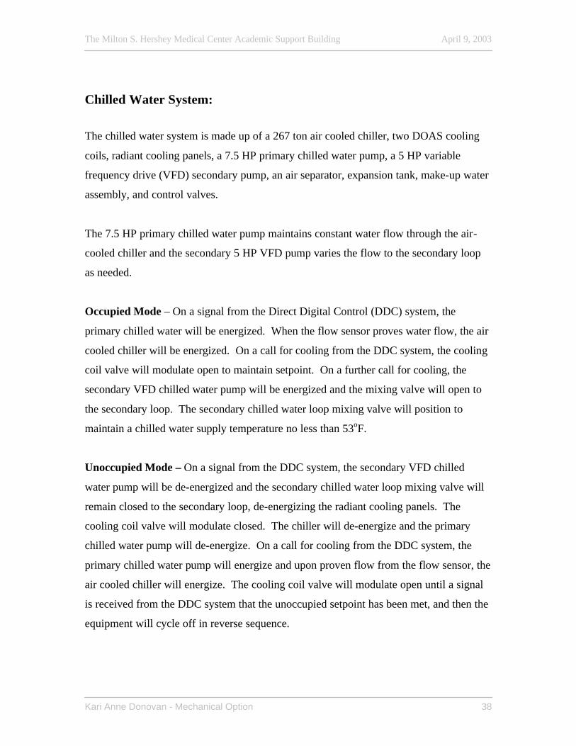
Chilled Water System:
The chilled water system is made up of a 267 ton air cooled chiller, two DOAS cooling
coils, radiant cooling panels, a 7.5 HP primary chilled water pump, a 5 HP variable
frequency drive (VFD) secondary pump, an air separator, expansion tank, make-up water
assembly, and control valves.
The 7.5 HP primary chilled water pump maintains constant water flow through the air-
cooled chiller and the secondary 5 HP VFD pump varies the flow to the secondary loop
as needed.
Occupied Mode – On a signal from the Direct Digital Control (DDC) system, the
primary chilled water will be energized. When the flow sensor proves water flow, the air
cooled chiller will be energized. On a call for cooling from the DDC system, the cooling
coil valve will modulate open to maintain setpoint. On a further call for cooling, the
secondary VFD chilled water pump will be energized and the mixing valve will open to
the secondary loop. The secondary chilled water loop mixing valve will position to
maintain a chilled water supply temperature no less than 53oF.
Unoccupied Mode – On a signal from the DDC system, the secondary VFD chilled
water pump will be de-energized and the secondary chilled water loop mixing valve will
remain closed to the secondary loop, de-energizing the radiant cooling panels. The
cooling coil valve will modulate closed. The chiller will de-energize and the primary
chilled water pump will de-energize. On a call for cooling from the DDC system, the
primary chilled water pump will energize and upon proven flow from the flow sensor, the
air cooled chiller will energize. The cooling coil valve will modulate open until a signal
is received from the DDC system that the unoccupied setpoint has been met, and then the
equipment will cycle off in reverse sequence.
The Milton S. Hershey Medical Center Academic Support Building April 9, 2003
Kari Anne Donovan - Mechanical Option 39
The Milton S. Hershey Medical Center Academic Support Building April 9, 2003
Kari Anne Donovan - Mechanical Option 40
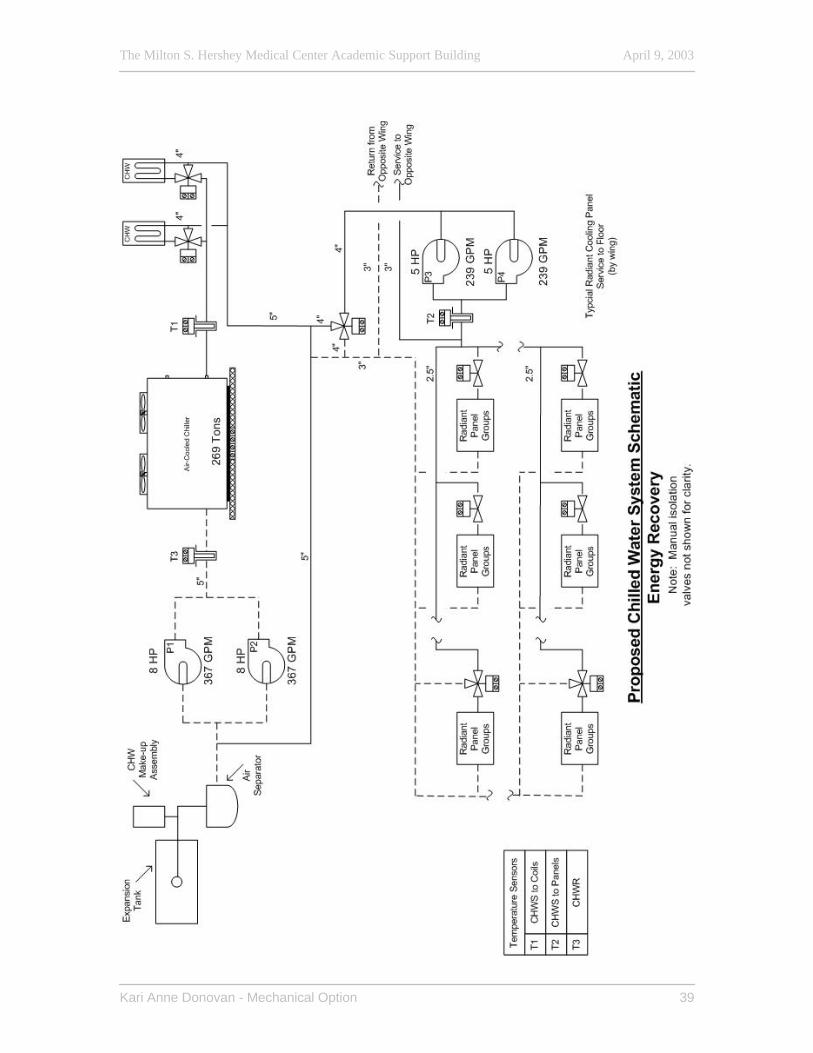
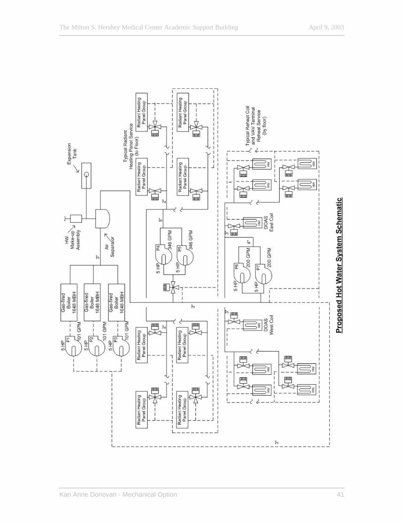
Hot Water System: The hot water system is made up of three gas-fired boilers, 1.5 hp constant speed primary
loop hot water pumps, 5 hp VFD secondary loop pumps, reheat units, expansion tank, air
separator, make-up water assembly, and control valves.
If the lead boiler is unable to maintain temperature setpoint, then the remaining boilers
and pumps will energize in the same sequence to maintain setpoint.
Secondary Hot Water Pumps –There are two secondary hot water loops. The DDC
controller energizes the coil loop secondary pump when the outside air temperature is
less than 45oF on a call for heating. The pump VFD modulates the pump speed to
maintain the secondary coil loop pressure setpoint. The heating coil valve modulates
open to maintain setpoint. On a further call for heating by the DDC system from the
space thermostats, the reheat coil valves modulate open to maintain space setpoint and
the secondary radiant heating panel pump energizes and the panel group valves modulate
open.
Primary Hot Water Pumps – On a call for heating from the DDC system, the lead
primary pump energizes, the combustion air intake damper opens. The boiler energizes
once the flow sensor proves water flow and the primary loop maintains the secondary hot
water temperature setpoint.
The Milton S. Hershey Medical Center Academic Support Building April 9, 2003
Kari Anne Donovan - Mechanical Option 41
The Milton S. Hershey Medical Center Academic Support Building April 9, 2003
Kari Anne Donovan - Mechanical Option 42
Typical Floor Sequence of Operation (Refer to Proposed Typical Floor Duct Layout, and Proposed Typical Radiant Panel Piping Plan – Appendix A)
Occupied Operation:
(See Air and Water Sequence of Operation above for detailed equipment operation).
On a call for cooling in Zones 1, 2, or 3 from an office thermostat, the radiant cooling
panel control valve serving the office will modulate open to meet the space thermostat
setpoint. On a call for heating in the open office space of Zone 2, the control valve for the
radiant heating panels will modulate open to meet the load. On a call for heating in Zone
1 or 3, the respective reheat coil control valve serving the zone will modulate open to
reheat the supply air from 45oF until one of the office thermostats reaches the dead band
between heating a cooling space setpoint conditions. When one thermostat is in the dead
band region, the supply air temperature will remain at the current elevated supply air
temperature and the offices whose thermostats are still calling for heating will be further
heated by their respective radiant heating panels. The individual control valves on the
office radiant heating panels will modulate open until their respective thermostat’s
setpoint is met.
Unoccupied Operation:
(See Air and Water Sequence of Operation above for detailed equipment operation).
In unoccupied mode, the supply air is recirculated and the DDC system will average the
Zone setpoints in the building. On a call for cooling, 100% outdoor air is supplied to the
space if the outdoor air temperature is less than the unoccupied space setpoint. If the
outdoor air temperature is not less than the unoccupied space setpoint, then the cooling
coil valve modulates open to ensure all space thermostats meet the unoccupied space
setpoint. On a call for heating in Zones 1 or 3, the terminal reheat control valve will
modulate open to meet or exceed the Zone thermostat unoccupied setpoint.
The Milton S. Hershey Medical Center Academic Support Building April 9, 2003
Kari Anne Donovan - Mechanical Option 43
Variable Supply Air Volume:
(See Air and Water Sequence of Operation above for detailed equipment operation).
The VAV boxes will be closed in unoccupied operation as determined by a CO2 sensor
in each conference room. On a call for heating in a conference room in unoccupied
operation, the control valve on the terminal reheat coil on the VAV box supplying the
conference rooms will modulate open until and the VAV box will modulate open to meet
the space thermostat setpoint. On a call for cooling in unoccupied operation, the VAV
box will modulate open to meet the space thermostat setpoint. In occupied operation as
determined by a CO2 sensor in each conference room, the VAV box will modulate open
to meet the space thermostat setpoint.
Modeling Accurately modeling the proposed mechanical system using a commercial software
package was difficult. Commercially available simulation software is not intended to be
used as a research tool to model newer technology. The DOAS/Radiant system was
simulated in Carrier’s Hourly Analysis Program (HAP v 4.1b) as a twp-pipe fan coil unit
with a common ventilation system. There were several discrepancies in the simulation
and actual intent of the building’s proposed system. The common ventilation system
indicated in the model was the DOAS system. It was not able to be modeled as a 100%
exhaust system and therefore there was a penalty to the cooling coil and the chiller for the
recirculated return air. The fan coil units indicated in the model were to simulate both the
radiant heating and cooing panels. Flow rates for the cooling and heating fluids for these
fan coil units were determined by the overall 10oF and 20oF temperature differential
intended for the DOAS cooling and heating coils, respectively. The actual radiant panels
in the proposed design operate at design temperature differential of 5oF and 2oF,
respectively, resulting in lower pumping energy consumption than the actual system
would operate at with the higher flow rates than were simulated. The fan coil units were
also simulated with no fan hp so there was no electrical power consumption included in
the simulation. The secondary pumps for both the radiant heating and cooling panels
The Milton S. Hershey Medical Center Academic Support Building April 9, 2003
Kari Anne Donovan - Mechanical Option 44
were added to the building heating and cooling plant specification sections. The enthalpy
wheel simulation was also processed differently than its intent in the proposed redesign.
The intent of the energy recovery system was to maintain a 45oF supply air temperature.
The program simulates the enthalpy wheel at the design effectiveness for the months
selected, regardless of the leaving condition intended. For this reason, there is a larger
cooling load on the cooling plant in the winter months if the enthalpy wheel is in
operation. However, if the enthalpy wheel is turned off for the winter months, there is a
penalty to the heating plant load. The simulation was run twice, simulating the enthalpy
wheel in operation yearlong and again in operation only half the year to extract the
heating and cooling loads pertaining to the proposed intention of the energy recovery
system.
Potential Energy Savings The existing system does not meet ASHRAE Standard 62 ventilation requirements, only
delivering 15,000 cfm of ventilation air to the building. A multiple spaces equation
analysis for the building yields a required ventilation flow rate of 43,500 cfm, a
difference of 28,500 cfm, almost double the original design. DOAS/ Radiant systems’
energy savings are often compared to all-air VAV systems that meet ASHRAE Standard
62 ventilation requirements. For the purpose of this energy analysis, the proposed
redesign potential energy savings was compared to the existing system as designed, and
the existing system with the corrected ventilation flow rate. Potential energy savings
were compared by energy consumed by system components as well as total system
energy consumption. (Refer to HVAC System Energy Comparison - Appendix B)
The total system potential energy savings of the proposed redesign is 60% of the existing
system with the corrected ventilation flow rate. The analysis of the component energy
savings was not as expected because both the chiller and pump energy consumption for
the proposed redesign system increased by 44% and 123%. The real savings was the
80% reduction in fan energy consumption by the proposed redesign. The potential
reduction in natural gas consumption of the boilers in the proposed redesign system is
The Milton S. Hershey Medical Center Academic Support Building April 9, 2003
Kari Anne Donovan - Mechanical Option 45
98%. Values were taken from HAP energy analysis with corrections made in the
proposed system for the energy recovery performance and pumping energy.
Based on the modeling results, approximately $42,628 a year (43%) can be saved in
energy costs.
First Cost The first cost of the proposed DOAS/Radiant mechanical system was estimated using the
existing GMP estimate prepared by the construction manager and RS Means Data. The
estimated 1st cost of the proposed mechanical redesign is 85% of the cost of the existing
mechanical system. This estimate includes the chilled water pipe savings inherent with
integrating the fire suppression and hydronic thermal transport systems. Redundant
equipment in the system estimates was removed. The controls package estimate, a
significant part of any mechanical system was neglected for both cases because a
breakdown for the existing system was not included. The most noteworthy change in the
controls package for the proposed redesign would be the substantial number of control
valves needed to provide individual office control. If the DOAS/Radiant system were to
be reviewed only on a 1st cost analysis, lumping zone offices together and controlling
flow with a single control valve could substantially reduce the individual control valves
for each perimeter office. However occupant comfort levels have a considerable effect
on worker productivity. While difficult to relay in numbers, the advantage of improved
indoor environment quality should be carefully weighed against an elevated 1st cost of the
system.
(Refer to HVAC Estimate – Appendix B)
The Milton S. Hershey Medical Center Academic Support Building April 9, 2003
Kari Anne Donovan - Mechanical Option 46
Conclusion The proposed mechanical system redesign meets ASHRAE Standard 62 ventilation
requirements as well as ASHRAE Standard 90.1 energy recovery and reheat guidelines.
There is a significant annual energy savings with out a substantial 1st cost penalty. The
equipment size is reduced and the possibility for further installation savings can be
obtained through system integration. Returning to the 9 areas for potential savings with a
DOAS/Radiant system as proposed (Mumma, 2001):
- The chiller required to meet the building cooling load was reduced by 183 tons (40%)
- The primary chilled water pump sizes were reduced from 15 hp to 7.5 hp - The ductwork installation cost was reduced by 75% - The total supply air cfm was reduced by 81% - The electrical service to the mechanical penthouse can obviously be reduced
due to the equipment size reduction (analysis follows) - No savings in acoustical ceiling tile due to pendant mounting radiant cooling
panels and existing in-lay radiant heating panels in perimeter spaces - Less lost rentable space due to mechanical shaft reduction due to reduced
supply air volume (not analyzed)
Redesign Impact on Building Systems (AE Breadth) The redesign of the building’s mechanical system impact other systems in the building as
well. Returning to the list of potential building system savings inherent in a
DOAS/Radiant system, the effects on the following systems were explored; fire
suppression and hydronic thermal transport system integration, electrical service to
mechanical equipment, and overall building height and layout changes. Potential energy
savings through a lighting redesign was also determined for a typical open office space in
the building.
Fire Suppression and Hydronic Thermal Transport Integration Air-water systems are viable for many cooling applications but have not been widely
used in the United States. The industry is bottom line burdened and air-water systems
generally have higher installation costs than a typical all air VAV system. The
integration of hydronic thermal transport systems (in this case radiant cooling panels) and
The Milton S. Hershey Medical Center Academic Support Building April 9, 2003
Kari Anne Donovan - Mechanical Option 47
the fire suppression systems has a potential to offset the added first cost of the radiant
panel system by using the thermal transport distribution piping as fire protection piping.
The integration of the two building systems still requires the combined system to meet
codes and standards. The NFPA allows the dual use of sprinkler piping for other
purposes in the NFPA 13 Standard provided the following (from W. Janus, 2001):
- The primary duty of the combined system is fire protection and all portions of the system must comply with NFPA 13.
- All components of the combined system must be rated for the working pressure of the sprinkler system.
- During a fire, water serving the sprinkler heads must not pass through auxiliary equipment or piping.
- The combined system must be a closed-loop circulating system. - There must be shutoff valves between the sprinkler system and all auxiliary
equipment and piping to ensure continuous availability while the auxiliary system is being serviced.
- The water must be less than 120oF. If water is greater than 100oF, intermediate or high temperature sprinklers must be used.
- Special signage needed for fire control valves. - No additives to the water that would inhibit the suppression characteristics of
the water. - Operation of the auxiliary system must not inhibit sprinkler alarms or cause
false alarms. The auxiliary system is the radiant cooling panels; therefore the high water temperature
constraint will not be a factor in system integration. The system is a closed-loop
circulating system and the chemical treatment for the system does not interfere with the
fire suppression characteristics of the water.
The existing sprinkler head layout was used to develop the Proposed Typical Integrated
Fire Suppression and Hydronic Thermal Transport System Plan. The required diffusers
and radiant cooling panels were also laid out to determine placement within the confines
of the sprinkler head grid. Sprinkler head branch lines were laid out first and then main
supply and return lines for the radiant cooling panels. The supply and return mains are
connected to every other sprinkler branch line. The supply lines to the radiant cooling
panels have globe valves shown to ensure continuous availability of the sprinkler system
during maintenance of the radiant panel system. Automatic control valves isolate the
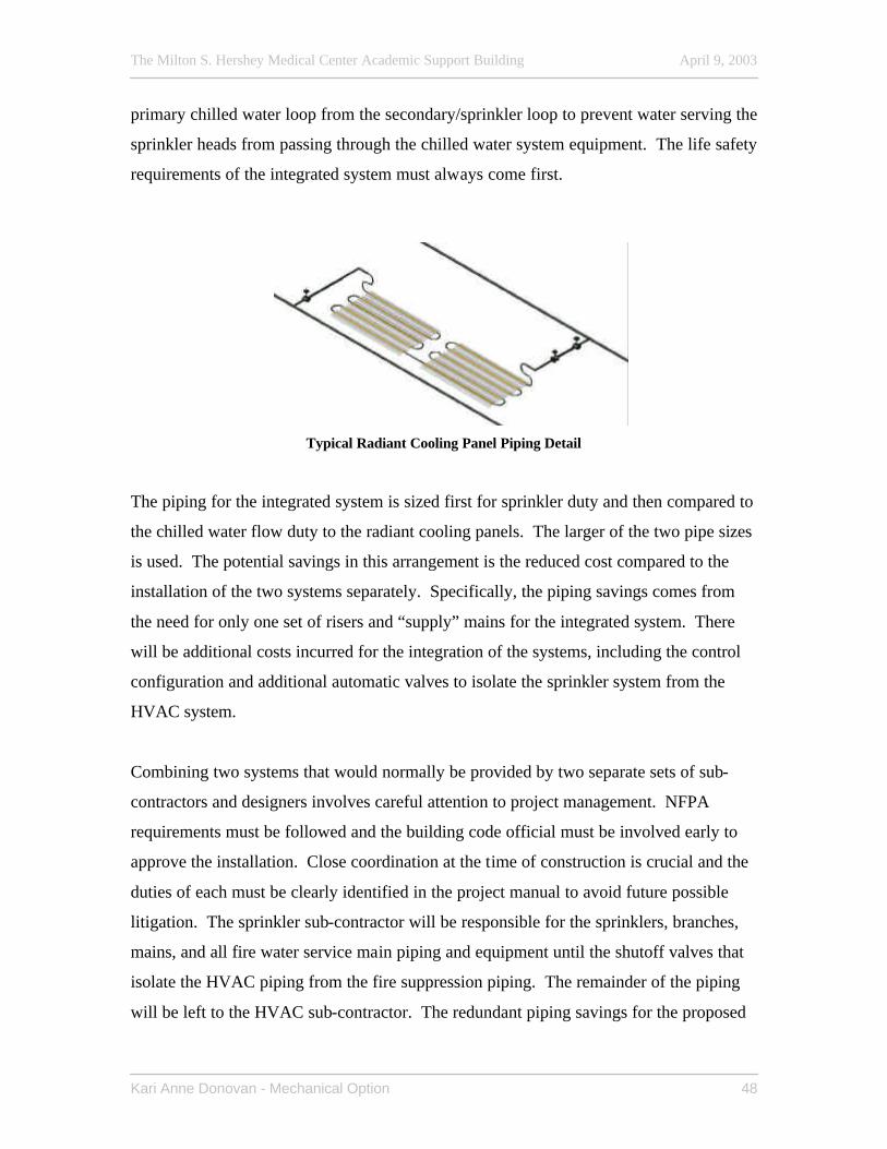
The Milton S. Hershey Medical Center Academic Support Building April 9, 2003
Kari Anne Donovan - Mechanical Option 48
primary chilled water loop from the secondary/sprinkler loop to prevent water serving the
sprinkler heads from passing through the chilled water system equipment. The life safety
requirements of the integrated system must always come first.
Typical Radiant Cooling Panel Piping Detail
The piping for the integrated system is sized first for sprinkler duty and then compared to
the chilled water flow duty to the radiant cooling panels. The larger of the two pipe sizes
is used. The potential savings in this arrangement is the reduced cost compared to the
installation of the two systems separately. Specifically, the piping savings comes from
the need for only one set of risers and “supply” mains for the integrated system. There
will be additional costs incurred for the integration of the systems, including the control
configuration and additional automatic valves to isolate the sprinkler system from the
HVAC system.
Combining two systems that would normally be provided by two separate sets of sub-
contractors and designers involves careful attention to project management. NFPA
requirements must be followed and the building code official must be involved early to
approve the installation. Close coordination at the time of construction is crucial and the
duties of each must be clearly identified in the project manual to avoid future possible
litigation. The sprinkler sub-contractor will be responsible for the sprinklers, branches,
mains, and all fire water service main piping and equipment until the shutoff valves that
isolate the HVAC piping from the fire suppression piping. The remainder of the piping
will be left to the HVAC sub-contractor. The redundant piping savings for the proposed
The Milton S. Hershey Medical Center Academic Support Building April 9, 2003
Kari Anne Donovan - Mechanical Option 49
integration for 10 open offices (2/wing/floor) is $75,540, obtained by eliminated the
smaller duty of the required sprinkler main piping and the HVAC main piping.
(Refer to Proposed Typical Integrated Fire Suppression and Hydronic Thermal Transport System Plan – Appendix A)
System Integration Sequence of Operation and Modified Flow Schematic Normal Operation: The primary pump will circulate water through the primary chilled
water loop and the VFD secondary pump will circulate water to the radiant cooling
panels on each floor through a common riser in each wing. There is a check valve
configuration in each wing at each floor that prevents HVAC flow across the flow switch
and between the supply and return mains on the floors. This assembly contains a fire
flow switch, two check valves, and a shut off valve. There is also a check valve CK V1
on each floor between the supply and return piping. The isolation valves V1 and V2 are
energized open when in normal operation mode. The control valves on each of the
radiant panel groups modulate to accept the flow required to satisfy the cooling needed as
determined by the space thermostat. The jockey pump maintains the hydronic system
pressure so the fire pump does not have to.
Fire Suppression Operation: When a sprinkler head is activated, the discharge flow
through the sprinkler head activates the alarm valve and sends a signal to the fire alarm
panel via the DDC system. The check valve configuration forces fire flow across the
flow switch. The DDC system then shuts down the primary and secondary chilled water
loop pumps, de-energizes the isolation valves V1 and V2 closed to isolate the main
HVAC equipment from the system, and closes the control valves on each radiant panel
group. The system pressure will drop below the set pressure and the fire pump will begin
to operate. The HVAC circulation flow in the return piping is reversed allowing the
sprinkler heads served by that line to be fed. The fire flow switch on the floor where the
sprinkler head is open helps to identify the location of the fire. The check valve CK V1
is typical for each floor and allows the HVAC supply piping to also feed the sprinkler
heads on the fire floor. There are hose outlet valves at each floor.
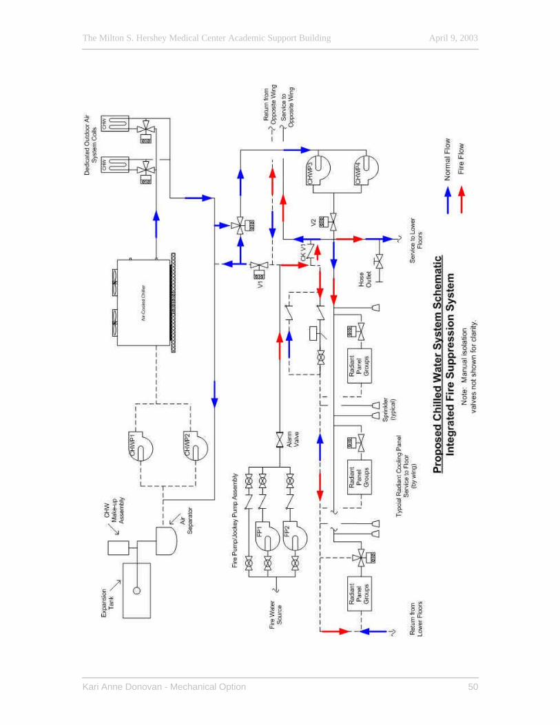
The Milton S. Hershey Medical Center Academic Support Building April 9, 2003
Kari Anne Donovan - Mechanical Option 50
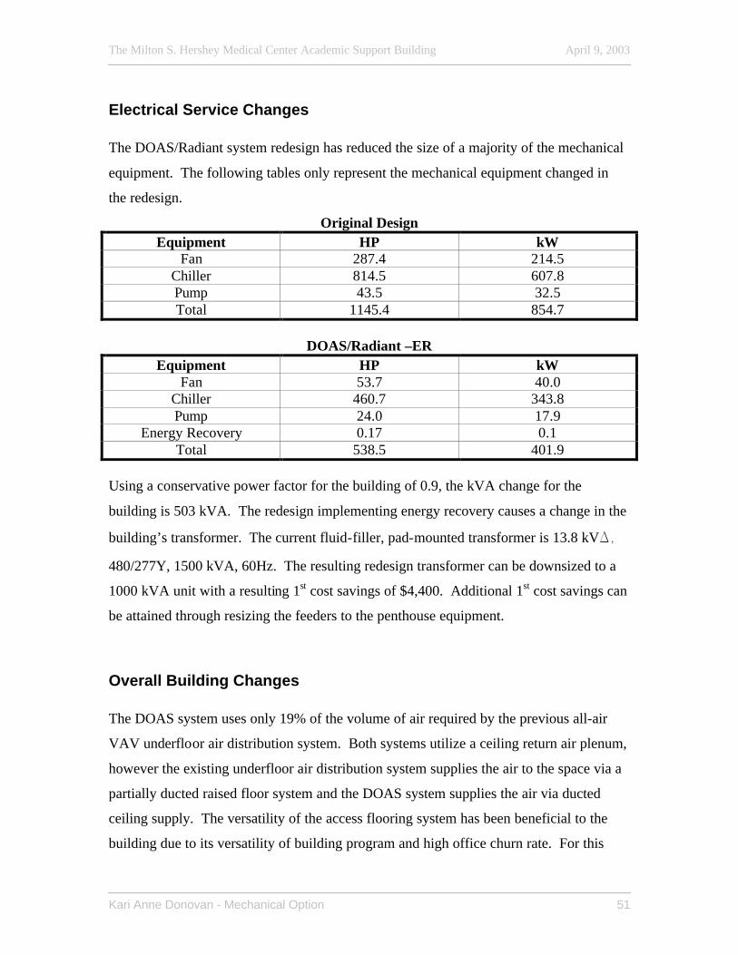
The Milton S. Hershey Medical Center Academic Support Building April 9, 2003
Kari Anne Donovan - Mechanical Option 51
Electrical Service Changes The DOAS/Radiant system redesign has reduced the size of a majority of the mechanical
equipment. The following tables only represent the mechanical equipment changed in
the redesign.
Original Design Equipment HP kW
Fan 287.4 214.5 Chiller 814.5 607.8 Pump 43.5 32.5 Total 1145.4 854.7
DOAS/Radiant –ER
Equipment HP kW Fan 53.7 40.0
Chiller 460.7 343.8 Pump 24.0 17.9
Energy Recovery 0.17 0.1 Total 538.5 401.9
Using a conservative power factor for the building of 0.9, the kVA change for the
building is 503 kVA. The redesign implementing energy recovery causes a change in the
building’s transformer. The current fluid-filler, pad-mounted transformer is 13.8 kVD,
480/277Y, 1500 kVA, 60Hz. The resulting redesign transformer can be downsized to a
1000 kVA unit with a resulting 1st cost savings of $4,400. Additional 1st cost savings can
be attained through resizing the feeders to the penthouse equipment.
Overall Building Changes The DOAS system uses only 19% of the volume of air required by the previous all-air
VAV underfloor air distribution system. Both systems utilize a ceiling return air plenum,
however the existing underfloor air distribution system supplies the air to the space via a
partially ducted raised floor system and the DOAS system supplies the air via ducted
ceiling supply. The versatility of the access flooring system has been beneficial to the
building due to its versatility of building program and high office churn rate. For this
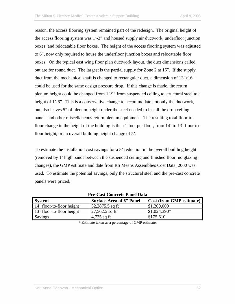
The Milton S. Hershey Medical Center Academic Support Building April 9, 2003
Kari Anne Donovan - Mechanical Option 52
reason, the access flooring system remained part of the redesign. The original height of
the access flooring system was 1’-3” and housed supply air ductwork, underfloor junction
boxes, and relocatable floor boxes. The height of the access flooring system was adjusted
to 6”, now only required to house the underfloor junction boxes and relocatable floor
boxes. On the typical east wing floor plan ductwork layout, the duct dimensions called
out are for round duct. The largest is the partial supply for Zone 2 at 16”. If the supply
duct from the mechanical shaft is changed to rectangular duct, a dimension of 13”x16”
could be used for the same design pressure drop. If this change is made, the return
plenum height could be changed from 1’-9” from suspended ceiling to structural steel to a
height of 1’-6”. This is a conservative change to accommodate not only the ductwork,
but also leaves 5” of plenum height under the steel needed to install the drop ceiling
panels and other miscellaneous return plenum equipment. The resulting total floor-to-
floor change in the height of the building is then 1 foot per floor, from 14’ to 13’ floor-to-
floor height, or an overall building height change of 5’.
To estimate the installation cost savings for a 5’ reduction in the overall building height
(removed by 1’ high bands between the suspended ceiling and finished floor, no glazing
changes), the GMP estimate and date from RS Means Assemblies Cost Data, 2000 was
used. To estimate the potential savings, only the structural steel and the pre-cast concrete
panels were priced.
Pre-Cast Concrete Panel Data
System Surface Area of 6” Panel Cost (from GMP estimate) 14’ floor-to-floor height 32,2875.5 sq ft $1,200,000 13’ floor-to-floor height 27,562.5 sq ft $1,024,390* Savings 4,725 sq ft $175,610
* Estimate taken as a percentage of GMP estimate.
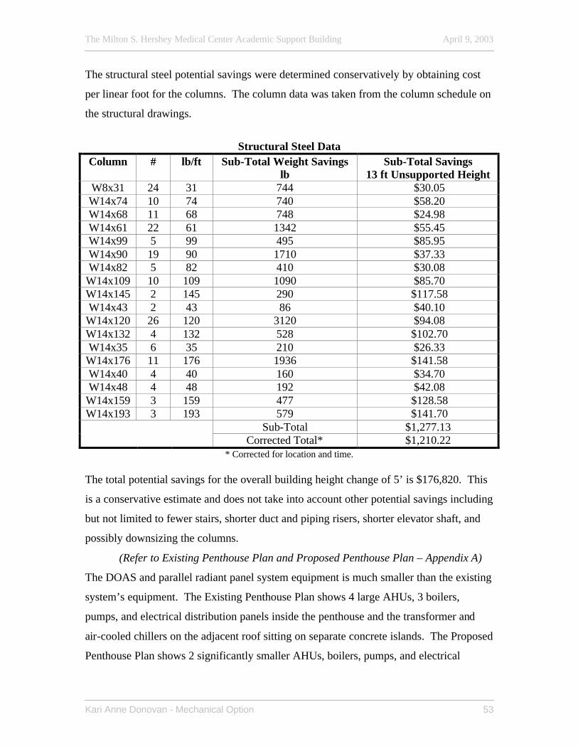
The Milton S. Hershey Medical Center Academic Support Building April 9, 2003
Kari Anne Donovan - Mechanical Option 53
The structural steel potential savings were determined conservatively by obtaining cost
per linear foot for the columns. The column data was taken from the column schedule on
the structural drawings.
Structural Steel Data
Column # lb/ft Sub-Total Weight Savings lb
Sub-Total Savings 13 ft Unsupported Height
W8x31 24 31 744 $30.05 W14x74 10 74 740 $58.20 W14x68 11 68 748 $24.98 W14x61 22 61 1342 $55.45 W14x99 5 99 495 $85.95 W14x90 19 90 1710 $37.33 W14x82 5 82 410 $30.08
W14x109 10 109 1090 $85.70 W14x145 2 145 290 $117.58 W14x43 2 43 86 $40.10
W14x120 26 120 3120 $94.08 W14x132 4 132 528 $102.70 W14x35 6 35 210 $26.33
W14x176 11 176 1936 $141.58 W14x40 4 40 160 $34.70 W14x48 4 48 192 $42.08
W14x159 3 159 477 $128.58 W14x193 3 193 579 $141.70
Sub-Total $1,277.13 Corrected Total* $1,210.22
* Corrected for location and time. The total potential savings for the overall building height change of 5’ is $176,820. This
is a conservative estimate and does not take into account other potential savings including
but not limited to fewer stairs, shorter duct and piping risers, shorter elevator shaft, and
possibly downsizing the columns.
(Refer to Existing Penthouse Plan and Proposed Penthouse Plan – Appendix A)
The DOAS and parallel radiant panel system equipment is much smaller than the existing
system’s equipment. The Existing Penthouse Plan shows 4 large AHUs, 3 boilers,
pumps, and electrical distribution panels inside the penthouse and the transformer and
air-cooled chillers on the adjacent roof sitting on separate concrete islands. The Proposed
Penthouse Plan shows 2 significantly smaller AHUs, boilers, pumps, and electrical
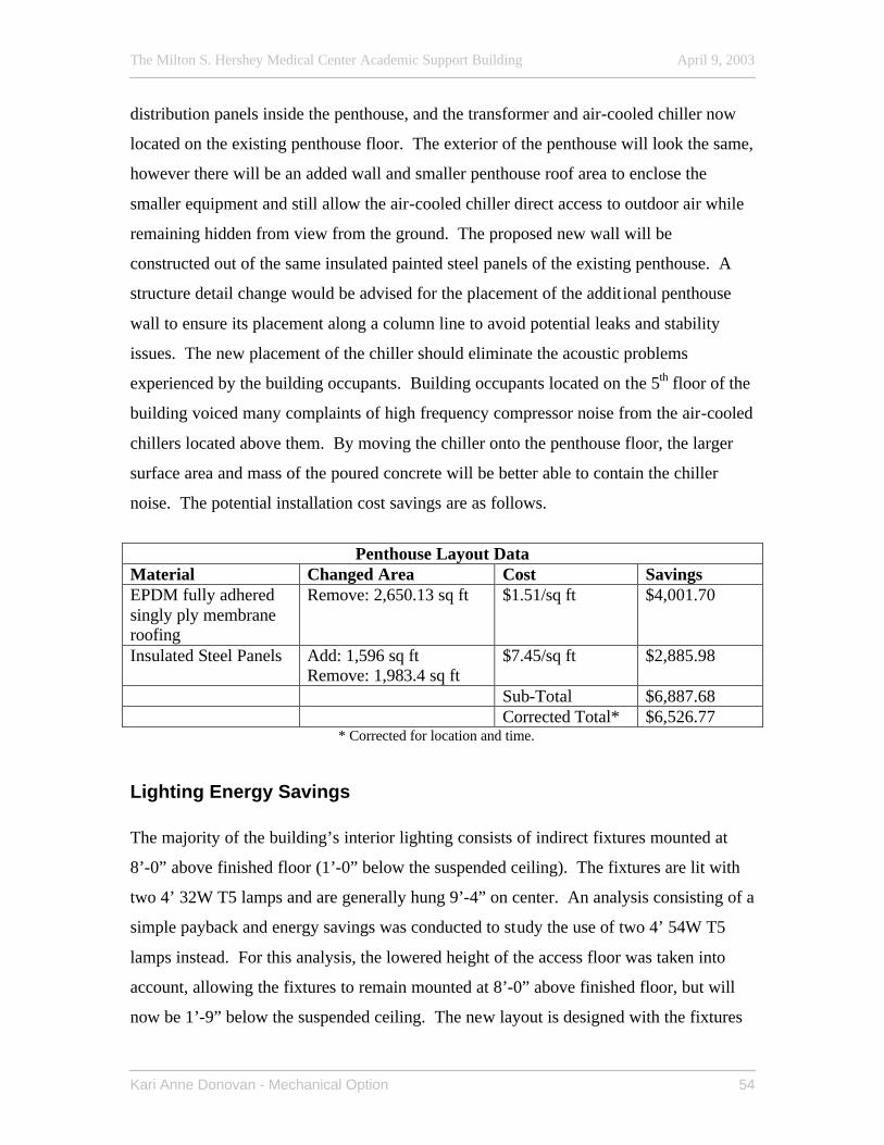
The Milton S. Hershey Medical Center Academic Support Building April 9, 2003
Kari Anne Donovan - Mechanical Option 54
distribution panels inside the penthouse, and the transformer and air-cooled chiller now
located on the existing penthouse floor. The exterior of the penthouse will look the same,
however there will be an added wall and smaller penthouse roof area to enclose the
smaller equipment and still allow the air-cooled chiller direct access to outdoor air while
remaining hidden from view from the ground. The proposed new wall will be
constructed out of the same insulated painted steel panels of the existing penthouse. A
structure detail change would be advised for the placement of the additional penthouse
wall to ensure its placement along a column line to avoid potential leaks and stability
issues. The new placement of the chiller should eliminate the acoustic problems
experienced by the building occupants. Building occupants located on the 5th floor of the
building voiced many complaints of high frequency compressor noise from the air-cooled
chillers located above them. By moving the chiller onto the penthouse floor, the larger
surface area and mass of the poured concrete will be better able to contain the chiller
noise. The potential installation cost savings are as follows.
Penthouse Layout Data
Material Changed Area Cost Savings EPDM fully adhered singly ply membrane roofing
Remove: 2,650.13 sq ft $1.51/sq ft $4,001.70
Insulated Steel Panels Add: 1,596 sq ft Remove: 1,983.4 sq ft
$7.45/sq ft $2,885.98
Sub-Total $6,887.68 Corrected Total* $6,526.77
* Corrected for location and time.
Lighting Energy Savings The majority of the building’s interior lighting consists of indirect fixtures mounted at
8’-0” above finished floor (1’-0” below the suspended ceiling). The fixtures are lit with
two 4’ 32W T5 lamps and are generally hung 9’-4” on center. An analysis consisting of a
simple payback and energy savings was conducted to study the use of two 4’ 54W T5
lamps instead. For this analysis, the lowered height of the access floor was taken into
account, allowing the fixtures to remain mounted at 8’-0” above finished floor, but will
now be 1’-9” below the suspended ceiling. The new layout is designed with the fixtures
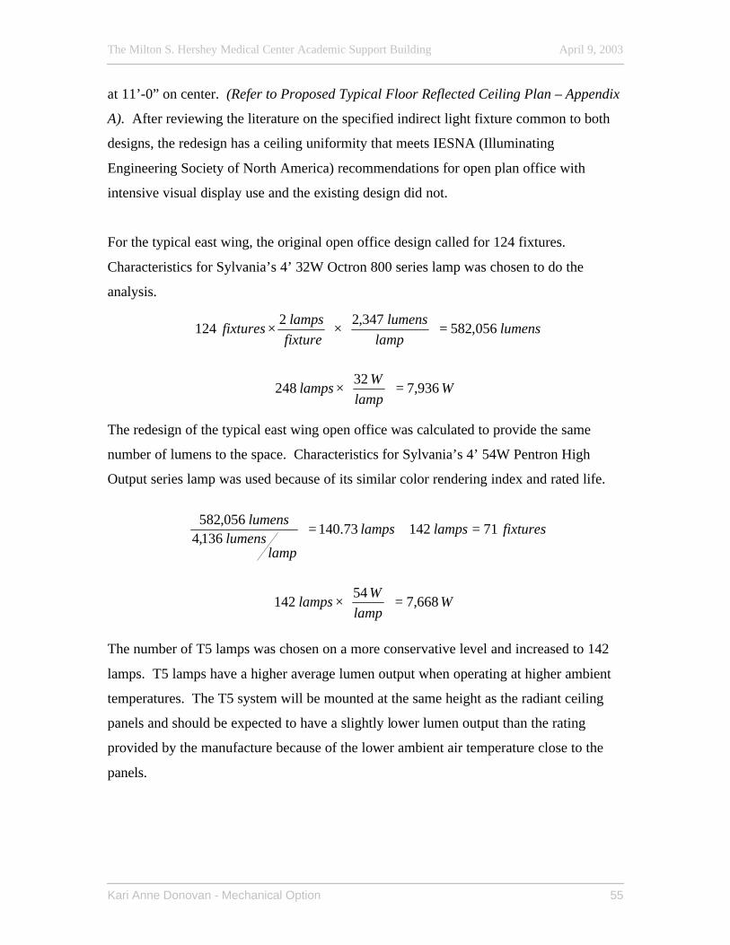
The Milton S. Hershey Medical Center Academic Support Building April 9, 2003
Kari Anne Donovan - Mechanical Option 55
at 11’-0” on center. (Refer to Proposed Typical Floor Reflected Ceiling Plan – Appendix
A). After reviewing the literature on the specified indirect light fixture common to both
designs, the redesign has a ceiling uniformity that meets IESNA (Illuminating
Engineering Society of North America) recommendations for open plan office with
intensive visual display use and the existing design did not.
For the typical east wing, the original open office design called for 124 fixtures.
Characteristics for Sylvania’s 4’ 32W Octron 800 series lamp was chosen to do the
analysis.
lumenslamp
lumensfixturelamps
fixtures 056,582347,22
124 =
×
×
Wlamp
Wlamps 936,7
32248 =
×
The redesign of the typical east wing open office was calculated to provide the same
number of lumens to the space. Characteristics for Sylvania’s 4’ 54W Pentron High
Output series lamp was used because of its similar color rendering index and rated life.
fixtureslampslamps
lamplumens
lumens7114273.140
136,4056,582
=≅=
Wlamp
Wlamps 668,7
54142 =
×
The number of T5 lamps was chosen on a more conservative level and increased to 142
lamps. T5 lamps have a higher average lumen output when operating at higher ambient
temperatures. The T5 system will be mounted at the same height as the radiant ceiling
panels and should be expected to have a slightly lower lumen output than the rating
provided by the manufacture because of the lower ambient air temperature close to the
panels.
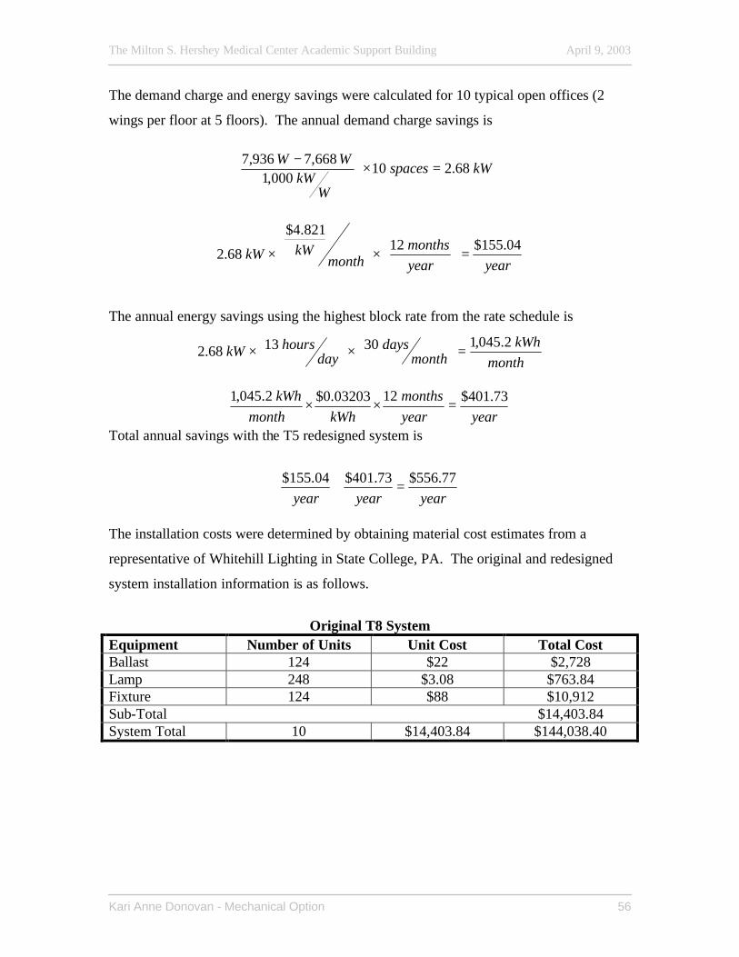
The Milton S. Hershey Medical Center Academic Support Building April 9, 2003
Kari Anne Donovan - Mechanical Option 56
The demand charge and energy savings were calculated for 10 typical open offices (2
wings per floor at 5 floors). The annual demand charge savings is
kWspaces
WkW
WW68.210
000,1668,7936,7
=×
−
yearyearmonths
monthkWkW
04.155$12821.4$
68.2 =
×
×
The annual energy savings using the highest block rate from the rate schedule is
monthkWh
monthdays
dayhourskW
2.045,1301368.2 =
×
×
yearyearmonths
kWhmonthkWh 73.401$1203203.0$2.045,1
=××
Total annual savings with the T5 redesigned system is
yearyearyear77.556$73.401$04.155$
=+
The installation costs were determined by obtaining material cost estimates from a
representative of Whitehill Lighting in State College, PA. The original and redesigned
system installation information is as follows.
Original T8 System
Equipment Number of Units Unit Cost Total Cost Ballast 124 $22 $2,728 Lamp 248 $3.08 $763.84 Fixture 124 $88 $10,912 Sub-Total $14,403.84 System Total 10 $14,403.84 $144,038.40
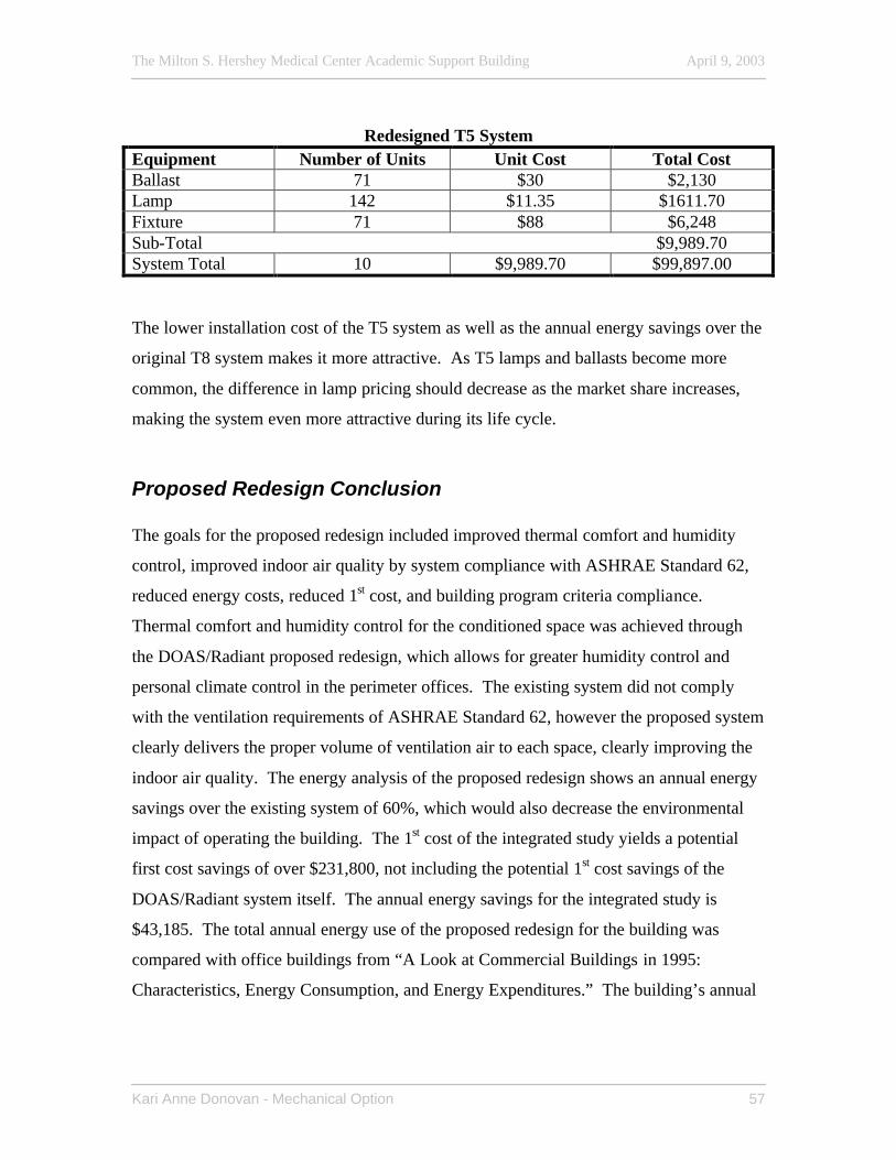
The Milton S. Hershey Medical Center Academic Support Building April 9, 2003
Kari Anne Donovan - Mechanical Option 57
Redesigned T5 System
Equipment Number of Units Unit Cost Total Cost Ballast 71 $30 $2,130 Lamp 142 $11.35 $1611.70 Fixture 71 $88 $6,248 Sub-Total $9,989.70 System Total 10 $9,989.70 $99,897.00 The lower installation cost of the T5 system as well as the annual energy savings over the
original T8 system makes it more attractive. As T5 lamps and ballasts become more
common, the difference in lamp pricing should decrease as the market share increases,
making the system even more attractive during its life cycle.
Proposed Redesign Conclusion The goals for the proposed redesign included improved thermal comfort and humidity
control, improved indoor air quality by system compliance with ASHRAE Standard 62,
reduced energy costs, reduced 1st cost, and building program criteria compliance.
Thermal comfort and humidity control for the conditioned space was achieved through
the DOAS/Radiant proposed redesign, which allows for greater humidity control and
personal climate control in the perimeter offices. The existing system did not comply
with the ventilation requirements of ASHRAE Standard 62, however the proposed system
clearly delivers the proper volume of ventilation air to each space, clearly improving the
indoor air quality. The energy analysis of the proposed redesign shows an annual energy
savings over the existing system of 60%, which would also decrease the environmental
impact of operating the building. The 1st cost of the integrated study yields a potential
first cost savings of over $231,800, not including the potential 1st cost savings of the
DOAS/Radiant system itself. The annual energy savings for the integrated study is
$43,185. The total annual energy use of the proposed redesign for the building was
compared with office buildings from “A Look at Commercial Buildings in 1995:
Characteristics, Energy Consumption, and Energy Expenditures.” The building’s annual
The Milton S. Hershey Medical Center Academic Support Building April 9, 2003
Kari Anne Donovan - Mechanical Option 58
energy consumption is 76% less energy per square foot than other office buildings polled
in the study.
The proposed integrated system redesign for the Academic Support Building shows merit
on the basis of the analyses performed within this academic project. More thorough
investigation and detailed design would validate and further define the potential of this
system for consideration in new construction.
Acknowledgements
AE Department
Dr. Stan Mumma, PhD, PE – Thesis faculty advisor
Terry Achey, Director of Facilities, Penn State College of Medicine
Facilities Staff, Penn State College of Medicine
Family and Friends
The Milton S. Hershey Medical Center Academic Support Building April 9, 2003
Kari Anne Donovan - Mechanical Option 59
References ASHRAE. 2001. ASHRAE Handbook of Fundamentals, 2001 (I-P Edition). Atlanta, GA: American Society of Heating, Refrigerating and Air-Conditioning Engineers, Inc. ASHRAE. 2001. ANSI/ASHRAE Standard 62-2001, Ventilation for acceptable indoor air quality. Atlanta, GA: American Society of Heating, Refrigerating and Air Conditioning Engineers, Inc. ASHRAE. 1999. ANSI/ASHRAE Standard 90.1-1999, Energy standard for buildings except low-rise residential buildings. Atlanta, GA: American Society of Heating, Refrigerating and Air-Conditioning Engineers, Inc. Bahnfleth, W.P. 1996. Synergisms in the Relationship of Chilled Water Thermal Storage and District Cooling. EPRI International Conference on Sustainable Thermal Energy Storage, Minneapolis, MN. Carrier. 2000. Electronic catalog equipment selection and performance CD. Carrier Corporation. Carrier. 2002. Hourly Analysis Program, v 4.1(b). Carrier Corporation. Coade, W. J. 1999. Conditioning Ventilation Air for Improved Performance and Air Quality. Heating/Piping/Air Conditioning, September, pp.49-55. Conroy, C. L., Mumma, S. A. 2001. Ceiling Radiant Cooling Panels as a Viable Distributed parallel Sensible Cooling Technology Integrated with Dedicated Outdoor Air Systems. ASHRAE Transactions 107. Construction Publishers & Consultants. 1999. RS Means Assemblies Cost Data 2000 25th annual edition. Kingston, MA: RS Means. Construction Publishers & Consultants. 2002. RS Means Building Construction Cost Data 2003 61st annual edition. Kingston, MA: RS Means. Construction Publishers & Consultants. 2002. RS Means Mechanical Cost Data 2003 61st annual edition. Kingston, MA: RS Means. Cote, A. E. 2000. Fire Protection Handbook, 18th ed. Quincy, MA: National Fire Protection Association. Energy Information Association. 1998. A Look at Commercial Buildings in 1995: Characteristics, Energy Consumption, and Energy Expenditures. Washington, DC: DOE.
The Milton S. Hershey Medical Center Academic Support Building April 9, 2003
Kari Anne Donovan - Mechanical Option 60
Hughes, S. D. 1988. Electrical Systems in Buildings. Albany, NY: Delmar Publishers, Inc. International District Energy Association. 2001. Benefits of District Energy. www.districtenergy.org/benefits.htm Janus, W.M. 2001. Integration of Hydronic Thermal Transport Systems with Fire Suppression Systems. ASHRAE IAQ Applications Newsletter, 2001. Mumma, S. A. 2001. Ceiling Panel Cooling Systems. ASHRAE Journal, November 2001. Mumma, S.A., Lee, B.W. 1998. Extension f the Multiple Spaces Concept of ASHRAE Standard 62 to Include Infiltration, Exhaust/Exfiltration, Interzonal Transfer, and Additional Short Circuit Paths. ASHRAE Transactions V 104 (2): pp. 1232- 1241. NFPA. 1998. National Electric Code (NEC) 1999. Quincy, MA: Nation Fire Protection Association. Penn State Milton S. Hershey Medical Center. 2001. Penn State College of Medicine Capital Planning. www.hmc.psu.edu/cap_plan/facts.htm Roth, K. W., 2002. Energy Consumption Characteristics of Commercial Building HVAC Systems Volume III: Energy Savings Potential. www.eere.energy.gov/buildings/documents/pdfs/hvacvolume3finalreport.pdf Reynolds, J. S., & Stein, B. 2000. Mechanical and Electrical Equipment for Buildings, 9th ed. Toronto, Canada: John Wiley & Sons, Inc. USA Coil & Air. USA coil and air, v 9.0. USA Coil & Air. York. 2002. Yorkworks software, v 6.00. York. ZBA, Inc. 1990. Engineering Study: Utility Expansion Program Phase 1.
Recommended