VSPEX ISV Solution Deployment Guide
THE LENOVO THINKSERVER – EMC VSPEX
PRIVATE CLOUD VALIDATED REFERENCE
ARCHITECTURE DEPLOYMENT GUIDE Scalable VMware® vSphereTM 5.1 for Up To 100 Virtual
Machines
EMC VSPEX powered by Lenovo ThinkServer
Abstract
The Lenovo ThinkServer - EMC VSPEX Private Cloud solution for VMware
vSphere 5.1 supports up to 100 virtual machines with redundant
server/network topology and highly available storage. This validated and
modular reference architecture built with proven best-of-breed
technologies is a complete virtualization solution for Private Cloud
deployments.
July 2013

2 <Document Title>
<Document Type>
<Copyright in formation here>
<Doc Title>
<Doc Type>
Part Number <Part #>
Contents
3 <Document Title>
<Document Type>
Contents
Chapter 1 Introduction 7
Purpose of this guide .............................................................................................. 8
Business value .......................................................................................................... 8
Scope ....................................................................................................................... 9
Audience ................................................................................................................. 9
Terminology ............................................................................................................. 9
Solution Tested ...................................................................................................... 10
Chapter 2 Solution Architecture 14
Architecture Overview ........................................................................................ 15
Logical Design View ............................................................................................. 17
Chapter 3 Solution Deployment 20
Deployment Overview ......................................................................................... 21
Deployment and Interoperability Prerequisites ................................................ 21
Pre-Deployment Tasks .......................................................................................... 22
Solution Deployment ............................................................................................ 22
Network Layer Installation and Configuration ............................................. 22
Server Installation and Configuration ........................................................... 27
Virtual Layer Installation and Configuration ................................................ 28
Installation and Configuration ............................................................................... 28
Storage Layer Installation and Configuration .............................................. 39
Chapter 4 Acknowledgements 53
Acknowledgements ............................................................................................. 54
Chapter 5 References 55
References ............................................................................................................ 56
Appendix A VLAN and IP Address Schema 58
VLAN and IP Address Schema ............................................................................ 59
Appendix B Compute Card Schema 60
CNA Network Assignments .................................................................................. 61
Appendix C Sample Network Configuration 62
Sample Network Configuration .......................................................................... 63
Contents
4 <Document Title>
<Document Type>
Fabric A ............................................................................................................. 63
Fabric B .............................................................................................................. 63
Appendix D Sample Cabling Guide 65
Sample Cabling Guide ........................................................................................ 66
Appendix E Sample Switch Port Labeling Guide 67
Sample Switch Port Labeling Guide .................................................................. 68
Appendix F Compute Firmware and Hardware Installation 69
PCIe Slot Assignment ............................................................................................ 70
Recommended Firmware Release (TBC) .......................................................... 70
Appendix G Power and Rack Position Planning 71
Power and Rack Position Planning..................................................................... 72
Contents
5 <Document Title>
<Document Type>
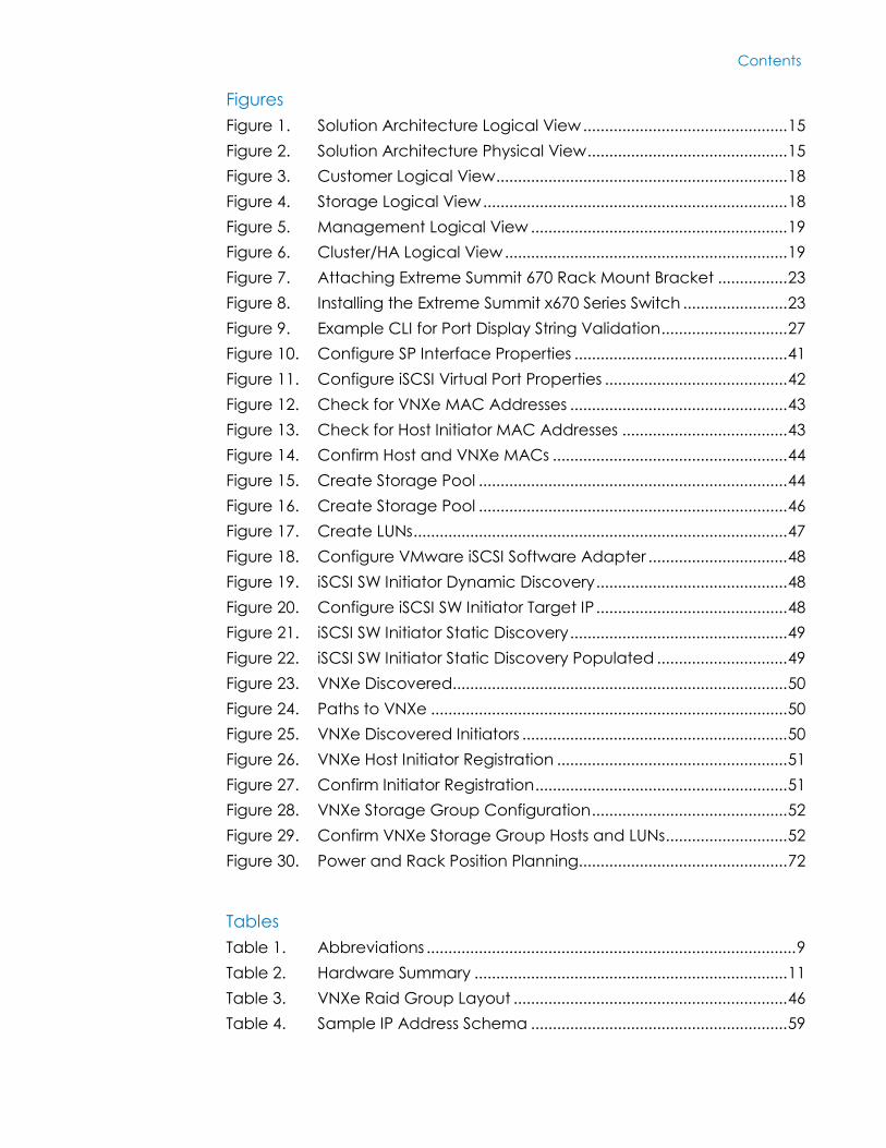
Figures
Figure 1. Solution Architecture Logical View ............................................... 15
Figure 2. Solution Architecture Physical View .............................................. 15
Figure 3. Customer Logical View ................................................................... 18
Figure 4. Storage Logical View ...................................................................... 18
Figure 5. Management Logical View ........................................................... 19
Figure 6. Cluster/HA Logical View ................................................................. 19
Figure 7. Attaching Extreme Summit 670 Rack Mount Bracket ................ 23
Figure 8. Installing the Extreme Summit x670 Series Switch ........................ 23
Figure 9. Example CLI for Port Display String Validation ............................. 27
Figure 10. Configure SP Interface Properties ................................................. 41
Figure 11. Configure iSCSI Virtual Port Properties .......................................... 42
Figure 12. Check for VNXe MAC Addresses .................................................. 43
Figure 13. Check for Host Initiator MAC Addresses ...................................... 43
Figure 14. Confirm Host and VNXe MACs ...................................................... 44
Figure 15. Create Storage Pool ....................................................................... 44
Figure 16. Create Storage Pool ....................................................................... 46
Figure 17. Create LUNs ...................................................................................... 47
Figure 18. Configure VMware iSCSI Software Adapter ................................ 48
Figure 19. iSCSI SW Initiator Dynamic Discovery ............................................ 48
Figure 20. Configure iSCSI SW Initiator Target IP ............................................ 48
Figure 21. iSCSI SW Initiator Static Discovery .................................................. 49
Figure 22. iSCSI SW Initiator Static Discovery Populated .............................. 49
Figure 23. VNXe Discovered............................................................................. 50
Figure 24. Paths to VNXe .................................................................................. 50
Figure 25. VNXe Discovered Initiators ............................................................. 50
Figure 26. VNXe Host Initiator Registration ..................................................... 51
Figure 27. Confirm Initiator Registration .......................................................... 51
Figure 28. VNXe Storage Group Configuration ............................................. 52
Figure 29. Confirm VNXe Storage Group Hosts and LUNs ............................ 52
Figure 30. Power and Rack Position Planning................................................ 72
Tables
Table 1. Abbreviations ..................................................................................... 9
Table 2. Hardware Summary ........................................................................ 11
Table 3. VNXe Raid Group Layout ............................................................... 46
Table 4. Sample IP Address Schema ........................................................... 59

Contents
6 <Document Title>
<Document Type>
Table 5. CNA Network Assignments ............................................................. 61
Table 6. Cabling Guide ................................................................................. 66
Table 7. Sample Switch Port Labeling Guide ............................................. 68
Table 8. PCIe Slot Assignment ....................................................................... 70
Table 9. Recommended Firmware Release ............................................... 70

Chapter 1: Introduction
7 <Document Title>
<Document Type>
Chapter 1 Introduction
This chapter presents the following topics:
Purpose of this guide .............................................................................................. 8
Business value .......................................................................................................... 8
Scope ....................................................................................................................... 9
Audience ................................................................................................................. 9
Terminology ............................................................................................................. 9
Solution Tested ...................................................................................................... 10
Chapter 1: Introduction
8 <Document Title>
<Document Type>
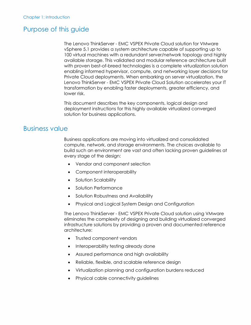
Purpose of this guide
The Lenovo ThinkServer - EMC VSPEX Private Cloud solution for VMware
vSphere 5.1 provides a system architecture capable of supporting up to
100 virtual machines with a redundant server/network topology and highly
available storage. This validated and modular reference architecture built
with proven best-of-breed technologies is a complete virtualization solution
enabling informed hypervisor, compute, and networking layer decisions for
Private Cloud deployments. When embarking on server virtualization, the
Lenovo ThinkServer - EMC VSPEX Private Cloud Solution accelerates your IT
transformation by enabling faster deployments, greater efficiency, and
lower risk.
This document describes the key components, logical design and
deployment instructions for this highly available virtualized converged
solution for business applications.
Business value
Business applications are moving into virtualized and consolidated
compute, network, and storage environments. The choices available to
build such an environment are vast and often lacking proven guidelines at
every stage of the design:
Vendor and component selection
Component interoperability
Solution Scalability
Solution Performance
Solution Robustness and Availability
Physical and Logical System Design and Configuration
The Lenovo ThinkServer - EMC VSPEX Private Cloud solution using VMware
eliminates the complexity of designing and building virtualized converged
infrastructure solutions by providing a proven and documented reference
architecture:
Trusted component vendors
Interoperability testing already done
Assured performance and high availability
Reliable, flexible, and scalable reference design
Virtualization planning and configuration burdens reduced
Physical cable connectivity guidelines
Chapter 1: Introduction
9 <Document Title>
<Document Type>
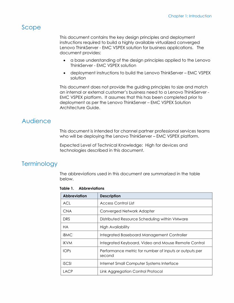
Scope
This document contains the key design principles and deployment
instructions required to build a highly available virtualized converged
Lenovo ThinkServer - EMC VSPEX solution for business applications. The
document provides:
a base understanding of the design principles applied to the Lenovo
ThinkServer - EMC VSPEX solution
deployment instructions to build the Lenovo ThinkServer – EMC VSPEX
solution
This document does not provide the guiding principles to size and match
an internal or external customer’s business need to a Lenovo ThinkServer -
EMC VSPEX platform. It assumes that this has been completed prior to
deployment as per the Lenovo ThinkServer – EMC VSPEX Solution
Architecture Guide.
Audience
This document is intended for channel partner professional services teams
who will be deploying the Lenovo ThinkServer – EMC VSPEX platform.
Expected Level of Technical Knowledge: High for devices and
technologies described in this document.
Terminology
The abbreviations used in this document are summarized in the table
below.
Table 1. Abbreviations
Abbreviation Description
ACL Access Control List
CNA Converged Network Adapter
DRS Distributed Resource Scheduling within VMware
HA High Availability
iBMC Integrated Baseboard Management Controller
iKVM Integrated Keyboard, Video and Mouse Remote Control
IOPs Performance metric for number of inputs or outputs per
second
iSCSI Internet Small Computer Systems Interface
LACP Link Aggregation Control Protocol
Chapter 1: Introduction
10 <Document Title>
<Document Type>
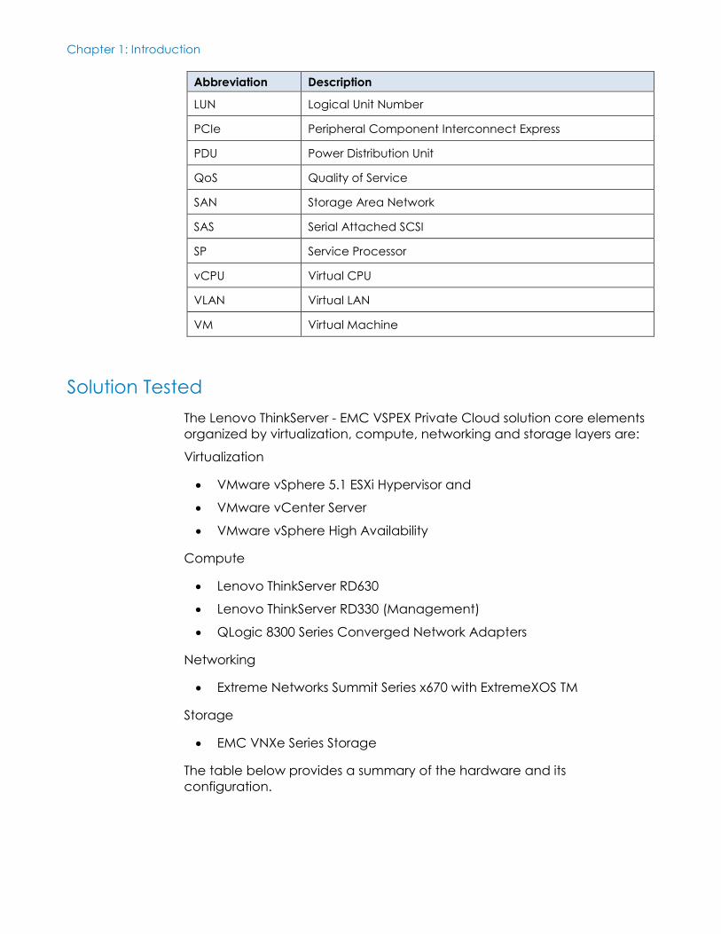
Abbreviation Description
LUN Logical Unit Number
PCIe Peripheral Component Interconnect Express
PDU Power Distribution Unit
QoS Quality of Service
SAN Storage Area Network
SAS Serial Attached SCSI
SP Service Processor
vCPU Virtual CPU
VLAN Virtual LAN
VM Virtual Machine
Solution Tested
The Lenovo ThinkServer - EMC VSPEX Private Cloud solution core elements
organized by virtualization, compute, networking and storage layers are:
Virtualization
VMware vSphere 5.1 ESXi Hypervisor and
VMware vCenter Server
VMware vSphere High Availability
Compute
Lenovo ThinkServer RD630
Lenovo ThinkServer RD330 (Management)
QLogic 8300 Series Converged Network Adapters
Networking
Extreme Networks Summit Series x670 with ExtremeXOS TM
Storage
EMC VNXe Series Storage
The table below provides a summary of the hardware and its
configuration.
Chapter 1: Introduction
11 <Document Title>
<Document Type>
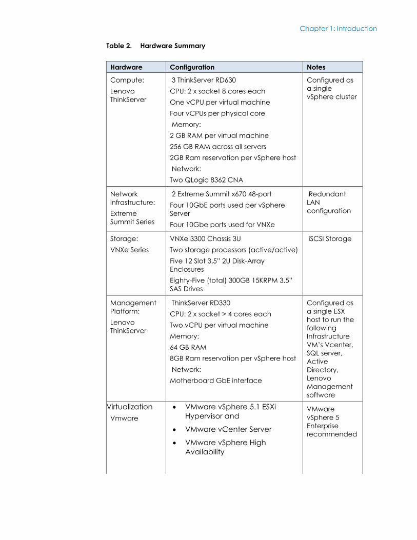
Table 2. Hardware Summary
Hardware Configuration Notes
Compute:
Lenovo
ThinkServer
3 ThinkServer RD630
CPU: 2 x socket 8 cores each
One vCPU per virtual machine
Four vCPUs per physical core
Memory:
2 GB RAM per virtual machine
256 GB RAM across all servers
2GB Ram reservation per vSphere host
Network:
Two QLogic 8362 CNA
Configured as
a single
vSphere cluster
Network
infrastructure:
Extreme
Summit Series
2 Extreme Summit x670 48-port
Four 10GbE ports used per vSphere
Server
Four 10Gbe ports used for VNXe
Redundant
LAN
configuration
Storage:
VNXe Series
VNXe 3300 Chassis 3U
Two storage processors (active/active)
Five 12 Slot 3.5” 2U Disk-Array
Enclosures
Eighty-Five (total) 300GB 15KRPM 3.5”
SAS Drives
iSCSI Storage
Management
Platform:
Lenovo
ThinkServer
ThinkServer RD330
CPU: 2 x socket > 4 cores each
Two vCPU per virtual machine
Memory:
64 GB RAM
8GB Ram reservation per vSphere host
Network:
Motherboard GbE interface
Configured as
a single ESX
host to run the
following
Infrastructure
VM’s Vcenter,
SQL server,
Active
Directory,
Lenovo
Management
software
Virtualization
Vmware
VMware vSphere 5.1 ESXi
Hypervisor and
VMware vCenter Server
VMware vSphere High
Availability
VMware
vSphere 5
Enterprise
recommended
Chapter 1: Introduction
12 <Document Title>
<Document Type>
The guiding principles for the solution design are:
Function
General purpose business applications that run in a virtual
environment.
Usability
Simplified debug, maintenance, upgrade and monitoring with pre-
determined network, storage and compute configurations, all
validated and documented with procedures.
Performance
Targets a general-purpose workload of up to 100 virtual machines
with a typical workload. Example workloads would be medium-to-
light database, web application or mail server processing.
Resilience / Reliability
This design is intended to provide N+1 redundancy throughout the
system to recover from typical single points of failure at each layer of
the system. Compute, network and storage all provide fail over and
fail back of services without impacting business applications.
Ease of Deployment
Channel partners trained on the platform can deploy a system ready
for business application service enablement in days versus weeks or
months for a similar solutions that are not pre-engineered
Scalability
Designed from the ground up to enable pay as you grow scaling.
Compute and storage layers have assigned ratios that allow
customers to incrementally grow each tier to match new business
demands. For example, a pre-engineered server to disk ratio is
designed into the architecture.
Manageability / Maintainability
The best practices to configure each component in the system are
documented to maximize the value of the tools used to manage a
converged Infrastructure platform. Some examples are: BIOS settings,
MTU size, onboard IPMI capabilities, power consumption and rack
design.
Economic and technical constraints, and tradeoffs
N+1 design requires powered and connected compute, storage and
network infrastructure to be lightly loaded during normal business
production hours. This architecture includes an optional server to
enable high availability at the compute layer, so if a server fails, the
system has enough resources to maintain business operations. The

Chapter 1: Introduction
13 <Document Title>
<Document Type>
design is an active/passive design aimed at availability and reduced
complexity.
Chapter 2: Solution Architecture
14 <Document Title>
<Document Type>
Chapter 2 Solution Architecture
This chapter presents the following topics:
Architecture Overview ........................................................................................ 15
Logical Design View ............................................................................................. 17
Chapter 2: Solution Architecture
15 <Document Title>
<Document Type>
Architecture Overview
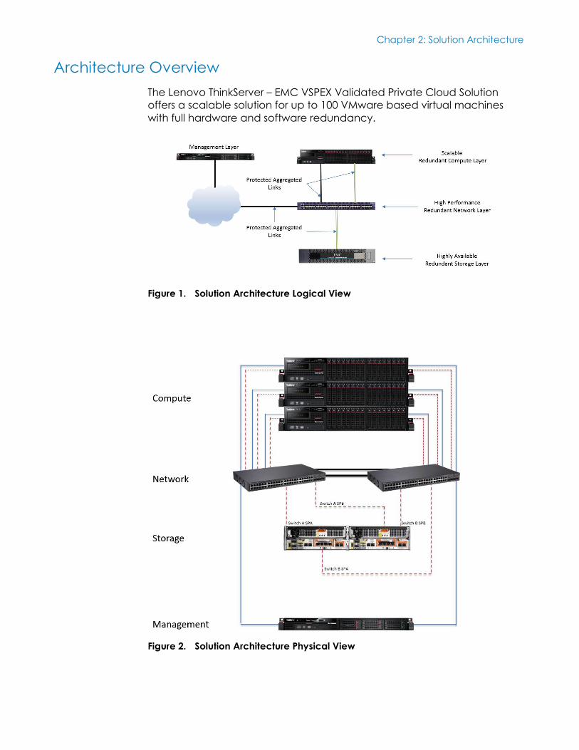
The Lenovo ThinkServer – EMC VSPEX Validated Private Cloud Solution
offers a scalable solution for up to 100 VMware based virtual machines
with full hardware and software redundancy.
Figure 1. Solution Architecture Logical View
Figure 2. Solution Architecture Physical View
Chapter 2: Solution Architecture
16 <Document Title>
<Document Type>
The solution architecture was designed and tested based on the goals
below to enable a robust compute platform for typical business
applications without sacrificing performance or availability:
Matched Compute Cores and Memory to disk spindles for typical
business work loads
Converged network adaptors equipped with hardware offload for
storage processing, allowing more CPU cycles for business
applications
Simple HA design (Active/Passive) N+1
Simple growth rules to increase capacity
In band VMware ESX management path over redundant interfaces;
other components are managed out of band (network, storage,
compute hardware)
Reduced cabling requirements
Converged layer 2 Ethernet fabric all storage, network and high
availability traffic.
Both of the storage and network communications fabrics have at least two
physical ten-gigabit Ethernet paths with one active and one passive path.
Network traffic is segregated on these physical links into at least five virtual
LANs (VLANs):
Compute
iSCSI and TCP processing off loaded to QLogic 8300 Converged
Network Adapters with hardware ASIC’s to reduce CPU utilization
and maximize compute layer CPU for business applications
Management
Management path QOS to ensure reachability of all devices under
all network conditions.
Storage
Dedicated high bandwidth/low latency physical links exclusively for
Ethernet based iSCSI storage traffic. Storage network traffic is
designed to provide access to storage at less than 3ms latency.
vMotion
High-bandwidth links for migrating and live migrating virtual machines
from one physical server to another
User Access
Bandwidth dedicated to application communication networks for
user to machine and machine to machine designated traffics. Many
User Access VLANs are typically provisioned.
Chapter 2: Solution Architecture
17 <Document Title>
<Document Type>
Fault Tolerance
Low latency/low bandwidth/high quality network utilized for
hypervisor to hypervisor health checks and resource scheduling. This
is used with the optional VMware Fault Tolerance host to host
replication of storage and state to a 2nd physical host.
Quality of Service (QoS) is applied to each shared VLAN to predictably
manage the behavior of these networks and to ensure shared links
prioritize application and storage traffic as needed.
With this VMware based solution, common infrastructure components are
virtualized and hosted on a separate dedicated management server:
VMware vSphere management server, Microsoft Windows 2012 Active
Directory, DHCP server, DNS server and Microsoft Windows SQL Server
2008R2 Standard.
Lenovo RD630 enterprise class servers are deployed in an N+1
configuration to provide full failover capabilities for all hosted virtual
application servers. A minimum of one physical core is allocated for every
four virtual CPUs (vCPU), with one vCPU to each virtualized application
server. This gives a final ratio of no more than four virtualized application
servers for each physical CPU core. At least two gigabytes of Physical
RAM is reserved for each virtual application.
Overall the solution is designed to be resilient to multiple simultaneous
failures at the network, computing, storage and power layer.
Best practices are documented throughout this document. However,
advanced design elements are highlighted but not described in detail, as
the goal for the solution is reduced complexity for install, support and
management of the system.
Logical Design View
Once a system is physically connected, it is often difficult to predict how or
where data will go without a logical component layer view to highlight the
relevant design elements. The Lenovo ThinkServer – EMC VSPEX Validated
Private Cloud Solution is designed to use an active/passive failure plane to
simplify the configuration, debugging, deployment and dependencies.
This logical view of the design is an important tool to simplify solution
debugging and for reliably predicting impacts of typical maintenance
activities. For example, the effect of rebooting an Ethernet switch must be
understood in advance to avoid any disruption to business applications
that are running in a live environment. The logical view for Customer
access, Management access, Storage access and Cluster/HA design are
provided below for reference.
Chapter 2: Solution Architecture
18 <Document Title>
<Document Type>
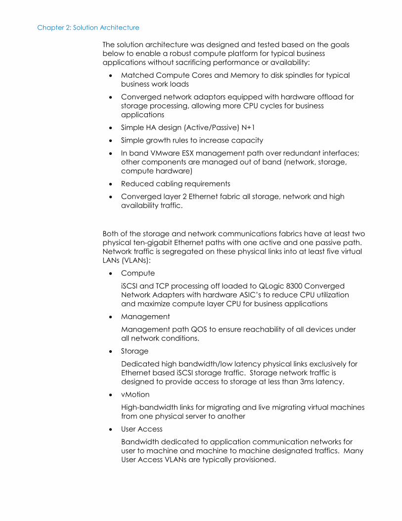
Figure 3. Customer Logical View
Customer Basic Design:
Active Path and Passive Path
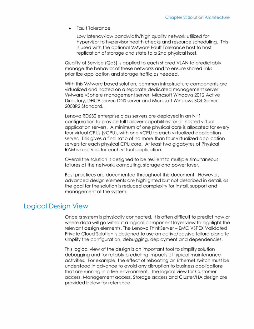
Figure 4. Storage Logical View
Storage Basic Design:
Active Path and Passive Path based on Hypervisor Multi-Pathing
Chapter 2: Solution Architecture
19 <Document Title>
<Document Type>
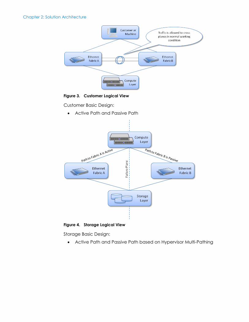
Figure 5. Management Logical View
Management Basic Design:
All devices have connection to management network with
dedicated management port out of band
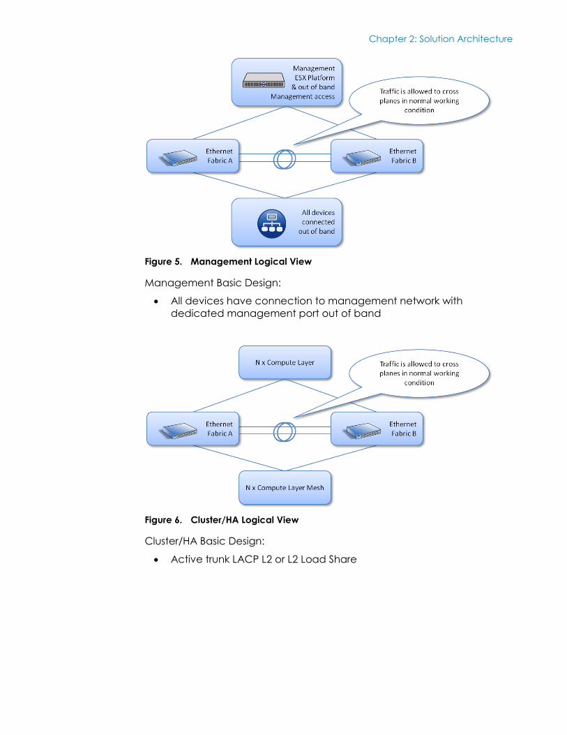
Figure 6. Cluster/HA Logical View
Cluster/HA Basic Design:
Active trunk LACP L2 or L2 Load Share
Chapter 3: Solution Deployment
20 <Document Title>
<Document Type>
Chapter 3 Solution Deployment
This chapter presents the following topics:
Deployment Overview ......................................................................................... 21
Deployment and Interoperability Prerequisites ................................................ 21
Pre-Deployment Tasks .......................................................................................... 22
Solution Deployment ............................................................................................ 22
Chapter 3: Solution Deployment
21 <Document Title>
<Document Type>
Deployment Overview
The deployment process has been designed to simplify system turn up at a
customer site. The high level steps are based on how the system was built
and tested and provide checkpoints throughout the process to ensure
that the system is deployed and ready for business applications once
complete. This document also serves as documentation repository for key
system variables that are required to operate the system and to provide to
customers.
Steps to Deployment:
1. Review all planning checklists in the Appendices
2. Complete Physical Rack installation based on Appendix G
3. Complete Network Layer installation and configuration
4. Complete Server installation and configuration
5. Complete Virtualization Layer installation and configuration
6. Complete Storage Layer installation and configuration
7. Add Storage to Virtualization Layer
8. Validate Solution Deployment
a. Guest VM to disk traffic test
b. Guest VM to network traffic test
c. Guest VM to Guest VM traffic test
d. Compute to Compute traffic test
Following these steps will reduce the time to install and debug all paths
between components and will ensure that the building blocks are built in
the correct order such that traffic tests can be successfully completed and
and the solution can be handed off to the customer.
Deployment and Interoperability Prerequisites
All components were tested with a basic configuration that ensures the
highest level of interoperability. For example, VLAN tagging was used to
separate traffic and vswitches. It is not expected that software specific
dependencies exist in the design and it is therefore recommended to
update all components to the latest versions available before going into
production. Each section outlines when software or firmware should be
updated before moving to the next building block.
Chapter 3: Solution Deployment
22 <Document Title>
<Document Type>
Pre-Deployment Tasks
It is important to ensure all sections for planning are complete before
deployment begins. Key checklists that should be reviewed before starting
a deployment are listed below. All checklists are found in the Appendices.
1. Power and Rack position planning
2. IP Address and VLAN planning
3. Server CNA and slot planning
4. Software version check on all components with required software
versions downloaded and available
It is highly recommended to keep a record of actual deployment data
that can be provided to the customer as part of the deployment handoff
process. The planning tables should be used as a reference for the data
that needs to be documented.
Solution Deployment
This section describes the deployment steps for the Lenovo ThinkServer –
EMC VSPEX Solution. The deployment must follow the order as described in
this section.
This section describes the installation and configuration steps for the
Network Layer of the Lenovo ThinkServer – EMC VSPEX Solution.
Pre-Installation Requirements
The following additional tools and equipment should be on-hand prior to
starting the Network Layer Installation and Configuration:
#1 Phillips screwdriver
Rack mounting screws
4x AC Power Cables
Extreme management console cable
Twin-Axial or SFP+/Fiber Cables for system connectivity
Complete and review actual IP Address and VLAN table for
deployment
Network Layer
Installation and
Configuration
Chapter 3: Solution Deployment
23 <Document Title>
<Document Type>
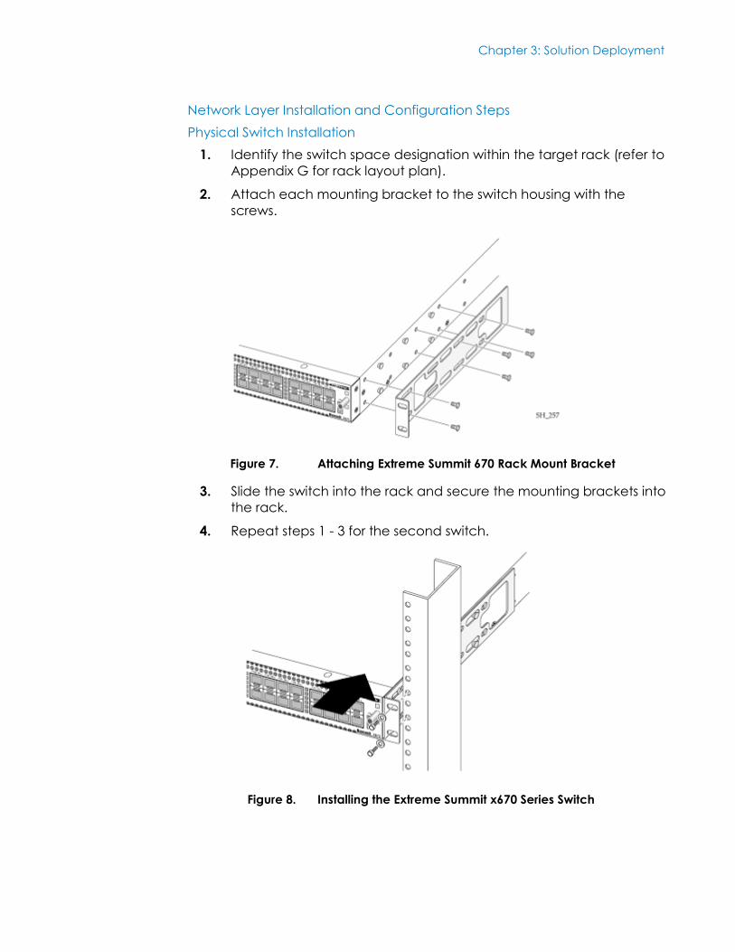
Network Layer Installation and Configuration Steps
Physical Switch Installation
1. Identify the switch space designation within the target rack (refer to
Appendix G for rack layout plan).
2. Attach each mounting bracket to the switch housing with the
screws.
Figure 7. Attaching Extreme Summit 670 Rack Mount Bracket
3. Slide the switch into the rack and secure the mounting brackets into
the rack.
4. Repeat steps 1 - 3 for the second switch.
Figure 8. Installing the Extreme Summit x670 Series Switch
Chapter 3: Solution Deployment
24 <Document Title>
<Document Type>
Power Cables
1. Power is supplied to all equipment in this design by redundant PDUs
with each PDU supplied from a discrete and independent source.
2. Attach power cords from the separate PDUs to both power
supplies located at the back of the switch.
3. Make sure the cables are neatly stowed to the side away from fan
intakes and exhaust.
4. Repeat steps 1 - 3 for the second switch.
SFPs and Cabling
Passive electrical twin-axial cables at 1M and 3M are recommended for all
interconnects although a mix of Extreme SFP and fibre optic cable can be
used as an alternative.
1. Review suggested cabling configuration included in Appendix D
and proceed with connecting equipment
2. Installing passive electrical twin-axial cable:
a. Holding the connector by its sides, insert the connector into the
port on the switch.
b. Push the connector into the port until you hear it click into
place.
3. Installing SFP and fibre optic cable combination:
a. Seat SFP modules into designated ports on the switch.
b. Connect SFPs via a fibre optic cable of appropriate length to
ensure tidy deployment.
4. Complete cabling for both switches.
Switch Initial configuration
1. Use the Summit® Family Switches Hardware Installation Guide to
complete the initial management access section for the Summit
x670.
2. Use the ExtremeXOS® Concepts Guide Software Version 15.1 to
configure:
Switch Name
SNMP Information
NTP
3. Save the configuration.
4. Repeat steps 1 - 3 for the second switch.
Chapter 3: Solution Deployment
25 <Document Title>
<Document Type>
Upgrade Firmware
1. Download image to secondary partition.
Example:
# download image 172.16.41.1 summitX-12.6.1.3.xos vr "VR-
Default" secondary
2. Set secondary partition as the boot image.
# use image secondary
3. Reboot extreme switch to restart with new installed firmware.
# reboot
4. Verify the firmware version.
# show version
5. Repeat steps 1 - 4 for the second switch.
Configure Jumbo Frames
Jumbo frames are used between endstations that support larger frame
sizes for more efficient transfers of bulk data. Both endstations involved in
the transfer must be capable of supporting jumbo frames. Jumbo frames
are disabled by default. The default size setting is 9216 which is the
maximum size that can be set and is the required setting for this solution.
Jumbo frames must be enabled on ports that are used in this deployment.
1. Login into the switch CLI interface.
2. Configure preferred jumbo frame size of 9216.
configure jumbo-frame-size 9216
3. Enable jumbo frames on ports that are used in this solution:
Example: Enable jumbo frames on a particular port
enable jumbo-frame ports 5
Example: Enable jumbo frames on multiple ports:
enable jumbo-frame ports 5,6,10
4. Repeat steps 1 - 3 for the second switch.
Configure Sharing
1. Login into switch ClI.
2. To configure sharing add ports using the following syntax:
configure sharing <master_port> add ports <port_list>
Example:
configure sharing 3:9 add ports 3:13
3. Repeat steps 1 - 2 for the second switch.
Chapter 3: Solution Deployment
26 <Document Title>
<Document Type>
Configure QoS Queues
Quality of Service (QoS) allows traffic groups higher priority access to
network resources in the event of network contention. Bandwidth can be
reserved for special groups of traffic. It is recommended that the Fault
Tolerance VLAN be configured with the highest traffic priority, and
sufficient bandwidth for the level (LockStep mirror, warm recover, etc) of
Fault Tolerance required by the deployed application.
Create and configure VLANs
1. Login into switch ClI.
2. Create desired VLAN and VLAN tag.
Example:
create VLAN "VSPX-CUS0"
configure VLAN VSPX-CUS0 tag 2100
3. Repeat for all VLANs in the VLAN list.
4. Repeat steps 1 - 3 for the second switch.
Refer to Appendix A for sample VLAN and IP Address layout.
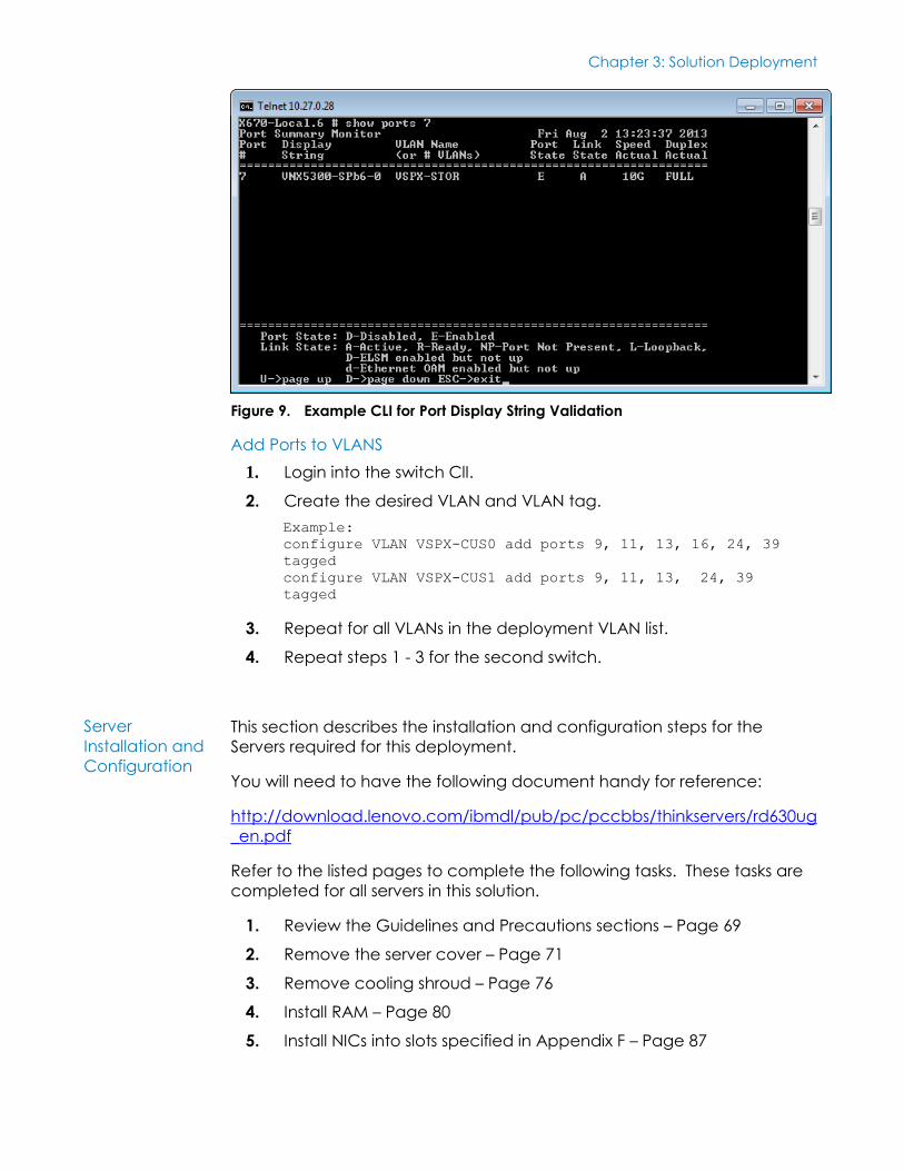
Configuring ports (names)
Descriptive port names, or “display-strings”, assist with debugging and
switch management. A list of suggested port display-strings are included
in Appendix E.
1. Log into the switch CLI
2. Configure the port display string.
Example:
configure ports 7 display-string “VNX5300-SPb6-0”
3. Validate port names are configured as expected.
Example:
show ports 7
Chapter 3: Solution Deployment
27 <Document Title>
<Document Type>
Figure 9. Example CLI for Port Display String Validation
Add Ports to VLANS
1. Login into the switch ClI.
2. Create the desired VLAN and VLAN tag.
Example:
configure VLAN VSPX-CUS0 add ports 9, 11, 13, 16, 24, 39
tagged
configure VLAN VSPX-CUS1 add ports 9, 11, 13, 24, 39
tagged
3. Repeat for all VLANs in the deployment VLAN list.
4. Repeat steps 1 - 3 for the second switch.
This section describes the installation and configuration steps for the
Servers required for this deployment.
You will need to have the following document handy for reference:
http://download.lenovo.com/ibmdl/pub/pc/pccbbs/thinkservers/rd630ug
_en.pdf
Refer to the listed pages to complete the following tasks. These tasks are
completed for all servers in this solution.
1. Review the Guidelines and Precautions sections – Page 69
2. Remove the server cover – Page 71
3. Remove cooling shroud – Page 76
4. Install RAM – Page 80
5. Install NICs into slots specified in Appendix F – Page 87
Server
Installation and
Configuration
Chapter 3: Solution Deployment
28 <Document Title>
<Document Type>
6. Install CPUs – Page 114
7. Re-install cooling shroud and server cover
8. Install redundant PSU – Page 108
9. Connect Ethernet cables following port recommendations in
Appendix D
10. Connect power cables
11. Update firmware for BIOS, BMC, iKVM and Raid Controller by using
ThinkServer EasyUpdate firmware updater. The latest version of Easy
Update can be found at http://www.lenovo.com/drivers and
navigating to the RD630 server.
12. Create a RAID1 local LUN for operating system boot – Page 64
13. Enable Hyper-Threading and Intel Virtualization, and configure Boot
order (Boot from Local RAID1 LUN) by using the pre-boot BIOS Setup
Utility – Page 53
14. Assign IP Addresses and user accounts to ThinkServer Management
Module (TMM) and iKVM using the guide found at
http://download.lenovo.com/ibmdl/pub/pc/pccbbs/thinkservers/r
d530rd630tmmug_en.pdf
This section describes the installation and configuration steps for the Virtual
Layer.
Pre-installation Requirements
VMware media
VMware Documentation - http://pubs.vmware.com/vsphere-51/index.jsp?topic=%2Fcom.vmware.vsphere.install.doc%2FGUID-7C9A1E23-7FCD-4295-9CB1-C932F2423C63.html
VMware license keys
Physical server installation completed
CNA drivers from Qlogic website
All appendix checklists completed
OS Installation
1. VMware DVD can be inserted in DVD drive (Keyboard mouse
monitor connected to server)
2. Reboot server and manually interrupt boot progress to boot from
DVD.
3. Set management IP address for out of band management port
during installation
4. Connect management port as per appendix cabling table
Virtual Layer
Installation and
Configuration
Installation and Configuration
Chapter 3: Solution Deployment
29 <Document Title>
<Document Type>
5. Verify ping to management port on OS before continuing
6. Download the vSphere client from this host by pointing a browser at
the management IP address provisioned above
7. Install vSphere client and login to ESX host to continue
8. OS Post Configuration (networking/management)
9. Check the ESX host networking configuration to ensure all cards
were detected by the installation
10. Enable SSH access on the ESX host (for driver installation)
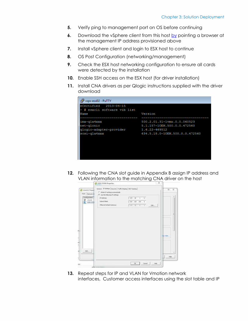
11. Install CNA drivers as per Qlogic instructions supplied with the driver
download
12. Following the CNA slot guide in Appendix B assign IP address and
VLAN information to the matching CNA driver on the host
13. Repeat steps for IP and VLAN for Vmotion network
interfaces, Customer access interfaces using the slot table and IP
Chapter 3: Solution Deployment
30 <Document Title>
<Document Type>
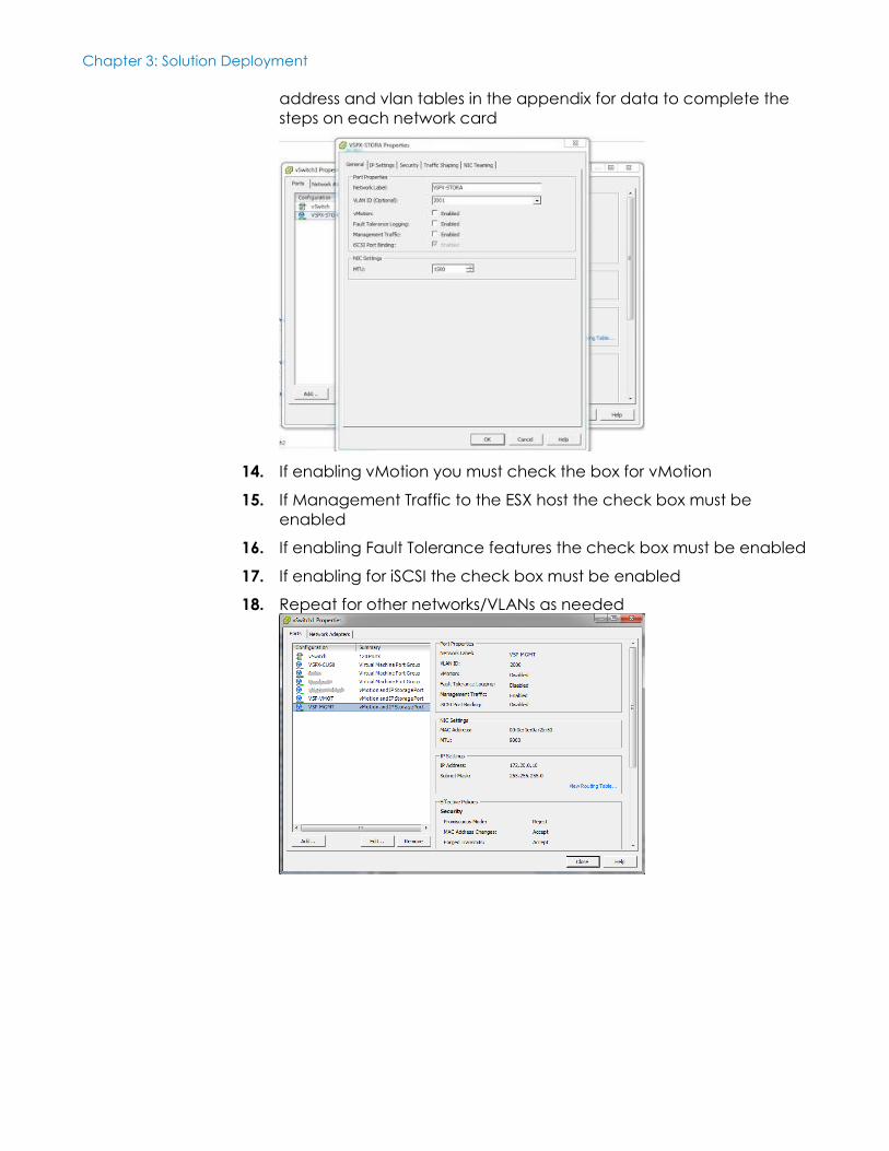
address and vlan tables in the appendix for data to complete the
steps on each network card
14. If enabling vMotion you must check the box for vMotion
15. If Management Traffic to the ESX host the check box must be
enabled
16. If enabling Fault Tolerance features the check box must be enabled
17. If enabling for iSCSI the check box must be enabled
18. Repeat for other networks/VLANs as needed
Chapter 3: Solution Deployment
31 <Document Title>
<Document Type>
vCenter/Licensing
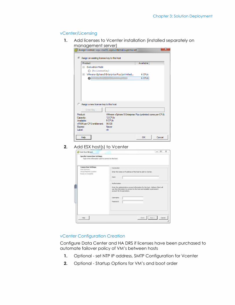
1. Add licenses to Vcenter installation (installed separately on
management server)
2. Add ESX host(s) to Vcenter
vCenter Configuration Creation
Configure Data Center and HA DRS if licenses have been purchased to
automate failover policy of VM’s between hosts
1. Optional - set NTP IP address, SMTP Configuration for Vcenter
2. Optional - Startup Options for VM’s and boot order
Chapter 3: Solution Deployment
32 <Document Title>
<Document Type>
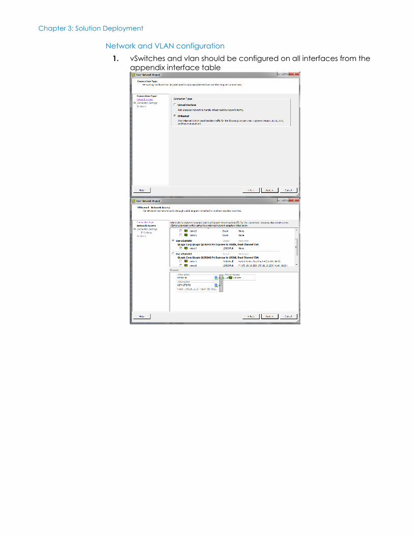
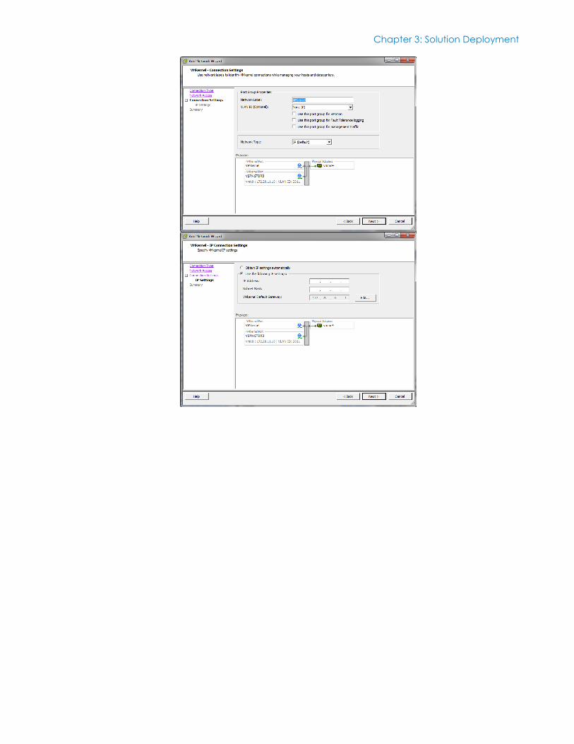
Network and VLAN configuration
1. vSwitches and vlan should be configured on all interfaces from the
appendix interface table
Chapter 3: Solution Deployment
33 <Document Title>
<Document Type>
Chapter 3: Solution Deployment
34 <Document Title>
<Document Type>
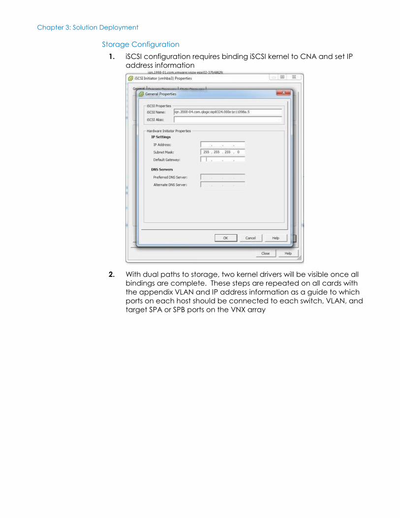
Storage Configuration
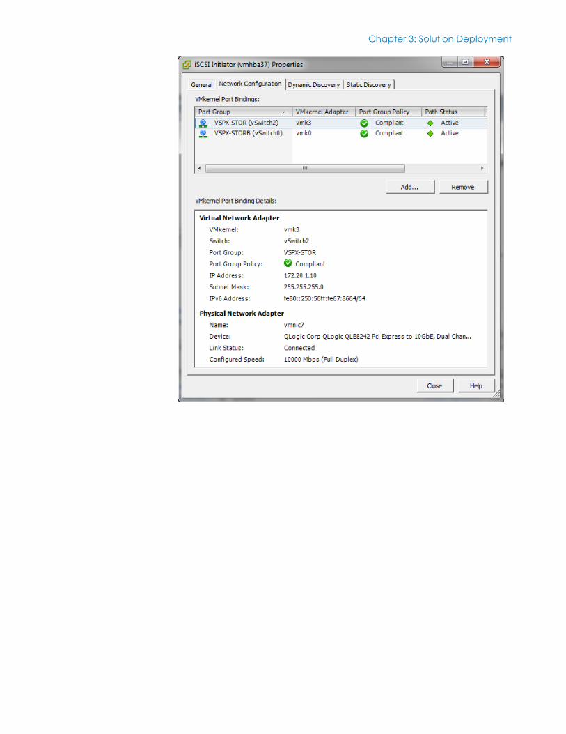
1. iSCSI configuration requires binding iSCSI kernel to CNA and set IP
address information
2. With dual paths to storage, two kernel drivers will be visible once all
bindings are complete. These steps are repeated on all cards with
the appendix VLAN and IP address information as a guide to which
ports on each host should be connected to each switch, VLAN, and
target SPA or SPB ports on the VNX array
Chapter 3: Solution Deployment
35 <Document Title>
<Document Type>
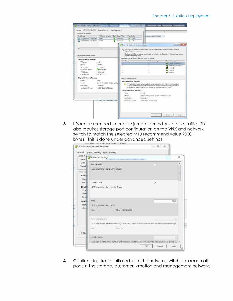
3. It’s recommended to enable jumbo frames for storage traffic. This
also requires storage port configuration on the VNX and network
switch to match the selected MTU recommend value 9000
bytes. This is done under advanced settings
4. Confirm ping traffic initiated from the network switch can reach all
ports in the storage, customer, vmotion and management networks.
Chapter 3: Solution Deployment
36 <Document Title>
<Document Type>
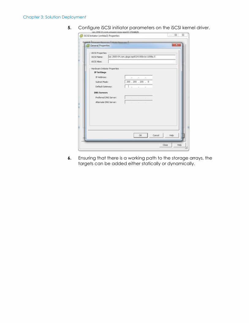
5. Configure iSCSI initiator parameters on the iSCSI kernel driver.
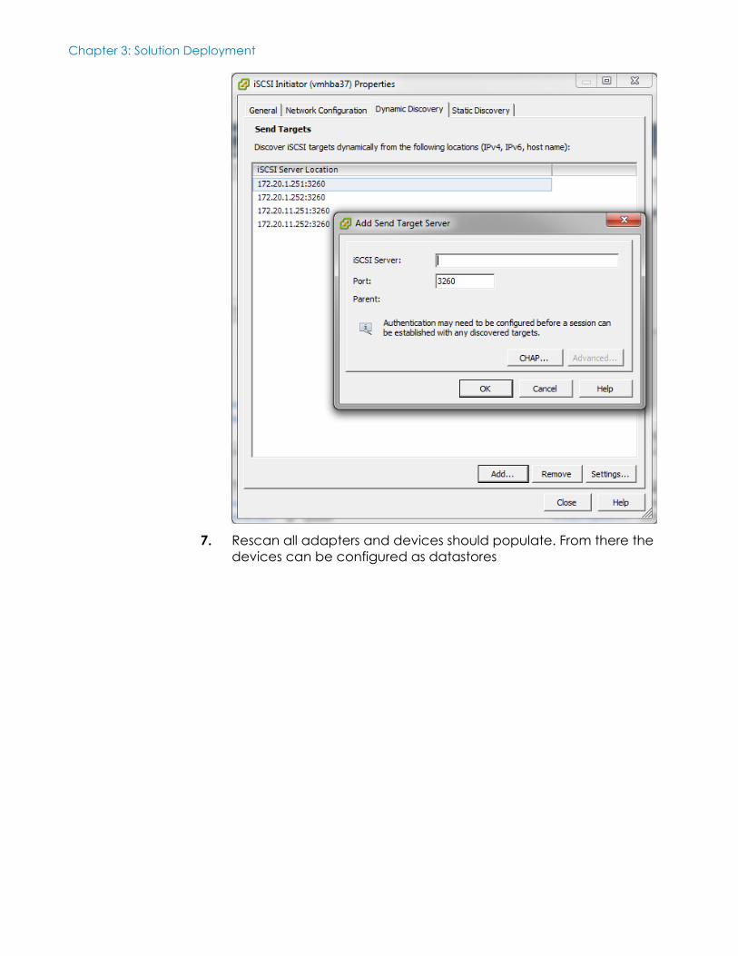
6. Ensuring that there is a working path to the storage arrays, the
targets can be added either statically or dynamically.
Chapter 3: Solution Deployment
37 <Document Title>
<Document Type>
Chapter 3: Solution Deployment
38 <Document Title>
<Document Type>
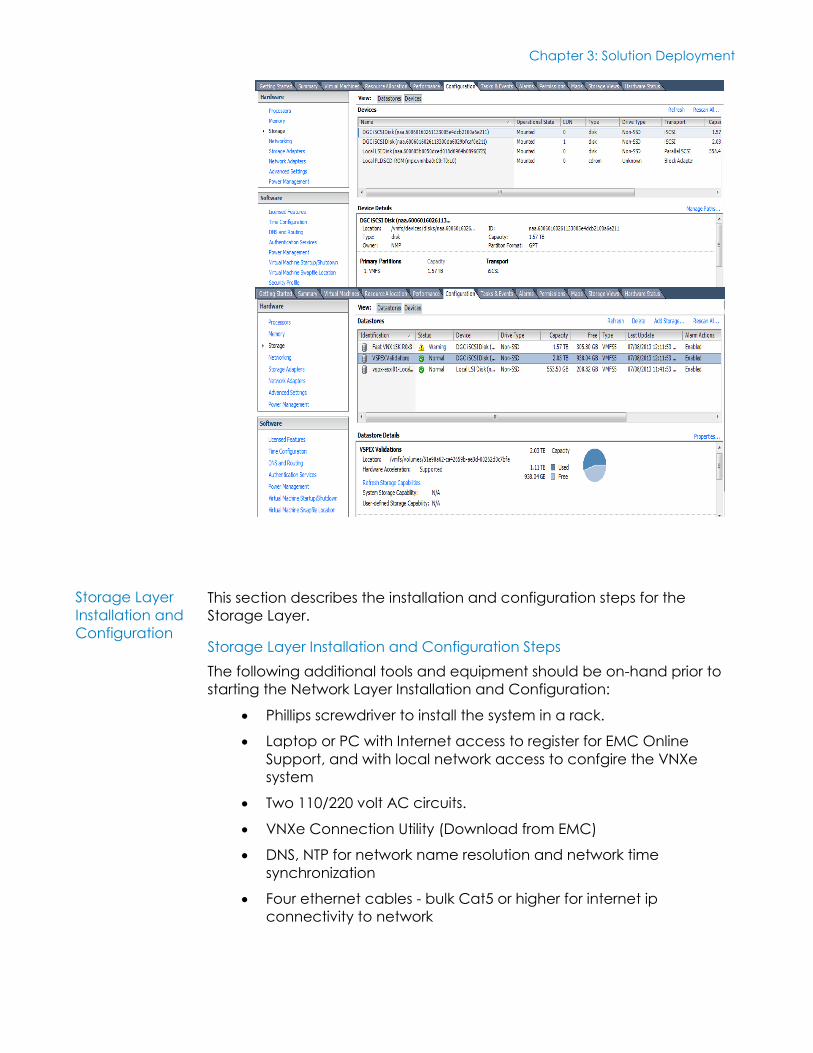
7. Rescan all adapters and devices should populate. From there the
devices can be configured as datastores
Chapter 3: Solution Deployment
39 <Document Title>
<Document Type>
This section describes the installation and configuration steps for the
Storage Layer.
Storage Layer Installation and Configuration Steps
The following additional tools and equipment should be on-hand prior to
starting the Network Layer Installation and Configuration:
Phillips screwdriver to install the system in a rack.
Laptop or PC with Internet access to register for EMC Online
Support, and with local network access to confgire the VNXe
system
Two 110/220 volt AC circuits.
VNXe Connection Utility (Download from EMC)
DNS, NTP for network name resolution and network time
synchronization
Four ethernet cables - bulk Cat5 or higher for internet ip
connectivity to network
Storage Layer
Installation and
Configuration
Chapter 3: Solution Deployment
40 <Document Title>
<Document Type>
Review the Sizing Guidelines section in the 100 VM Reference
Architecture document.
Reference documentation:
Quickstart Guide:
https://community.emc.com/servlet/JiveServlet/downloadBody/1
6485-102-4-65899/docu31492_VNXe-Series-Quick-Start.pdf
100 VM Reference Architecture Document:
http://www.emc.com/collateral/technical-
documentation/h11328-vspex-pi-pc-vmw-vnxe.pdf
Unpack VNXe, DAEs, Drives and Accessories
1. Unpack (1)VNXe DPE and (5)DAEs
2. Insert drives into DPE and DAE slots if they have not already been
installed.
3. Start with DPE and insert drives all free slots.
4. Repeat for DAE 1 and DAE 2.
5. Insert drives into slots 0-13 in DAE’s 3 and 4
6. Insert drives into slots 0-6 in DAE 5.
7. Install rack rails for DAEs and DPE into frame as per rack layout
diagram
VNXe Installation and Initial Configuration
Refer to the VNXe System Installation Guide (bundled in with the VNXe
system) for details.
1. Connect cables between DPE and DAEs and connect DPE to
Extreme Networks switch
2. Connect power to VNXe components and wait until the LEDs
indicate that the system is ready.
3. Connect the SPA and SPB Ports (0 and 1) to the Extreme switches as
defined in Appendix D.
4. Download and install the VNXe Connection Utility to assign a static
IP address to the VNXe system
5. Point a web browser to the ip address assigned to the VNXe in the
previous step
6. Login to Unisphere with the following credentials:
Username: admin
Password: Password123#
Chapter 3: Solution Deployment
41 <Document Title>
<Document Type>
7. The Unisphere Configuration Wizard will guide you through
configuring the following system settings:
Passwords for system administrators and service accounts
ESRS and ConnectEMC features for advanced proactive
EMC support
DNS and NTP time synchronization
8. Skip Storage Pool Configuration
9. Obtain license files and complete system registration
10. Update system software, firmware and language packs following
the available online guides.
11. Assign IP’s to VNXe iSCSI interfaces.
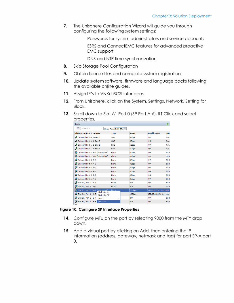
12. From Unisphere, click on the System, Settings, Network, Setting for
Block.
13. Scroll down to Slot A1 Port 0 (SP Port A-6), RT Click and select
properties.
Figure 10. Configure SP Interface Properties
14. Configure MTU on the port by selecting 9000 from the MTY drop
down.
15. Add a virtual port by clicking on Add, then entering the IP
information (address, gateway, netmask and tag) for port SP-A port
0.
Chapter 3: Solution Deployment
42 <Document Title>
<Document Type>
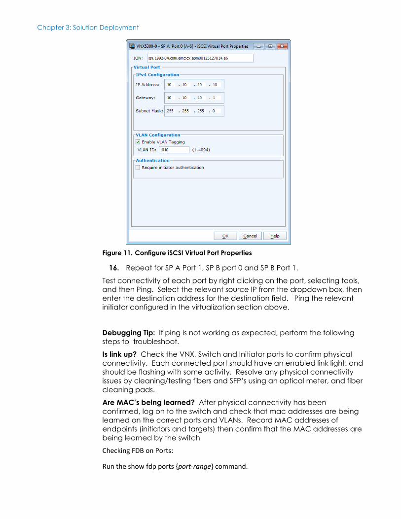
Figure 11. Configure iSCSI Virtual Port Properties
16. Repeat for SP A Port 1, SP B port 0 and SP B Port 1.
Test connectivity of each port by right clicking on the port, selecting tools,
and then Ping. Select the relevant source IP from the dropdown box, then
enter the destination address for the destination field. Ping the relevant
initiator configured in the virtualization section above.
Debugging Tip: If ping is not working as expected, perform the following
steps to troubleshoot.
Is link up? Check the VNX, Switch and Initiator ports to confirm physical
connectivity. Each connected port should have an enabled link light. and
should be flashing with some activity. Resolve any physical connectivity
issues by cleaning/testing fibers and SFP’s using an optical meter, and fiber
cleaning pads.
Are MAC’s being learned? After physical connectivity has been
confirmed, log on to the switch and check that mac addresses are being
learned on the correct ports and VLANs. Record MAC addresses of
endpoints (initiators and targets) then confirm that the MAC addresses are
being learned by the switch
Checking FDB on Ports:
Run the show fdp ports {port-range} command.
Chapter 3: Solution Deployment
43 <Document Title>
<Document Type>
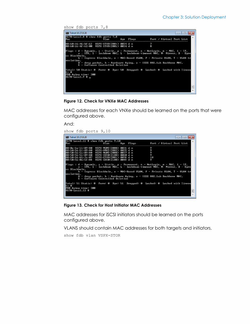
show fdb ports 7,8
Figure 12. Check for VNXe MAC Addresses
MAC addresses for each VNXe should be learned on the ports that were
configured above.
And:
show fdb ports 9,10
Figure 13. Check for Host Initiator MAC Addresses
MAC addresses for iSCSI initiators should be learned on the ports
configured above.
VLANS should contain MAC addresses for both targets and initiators.
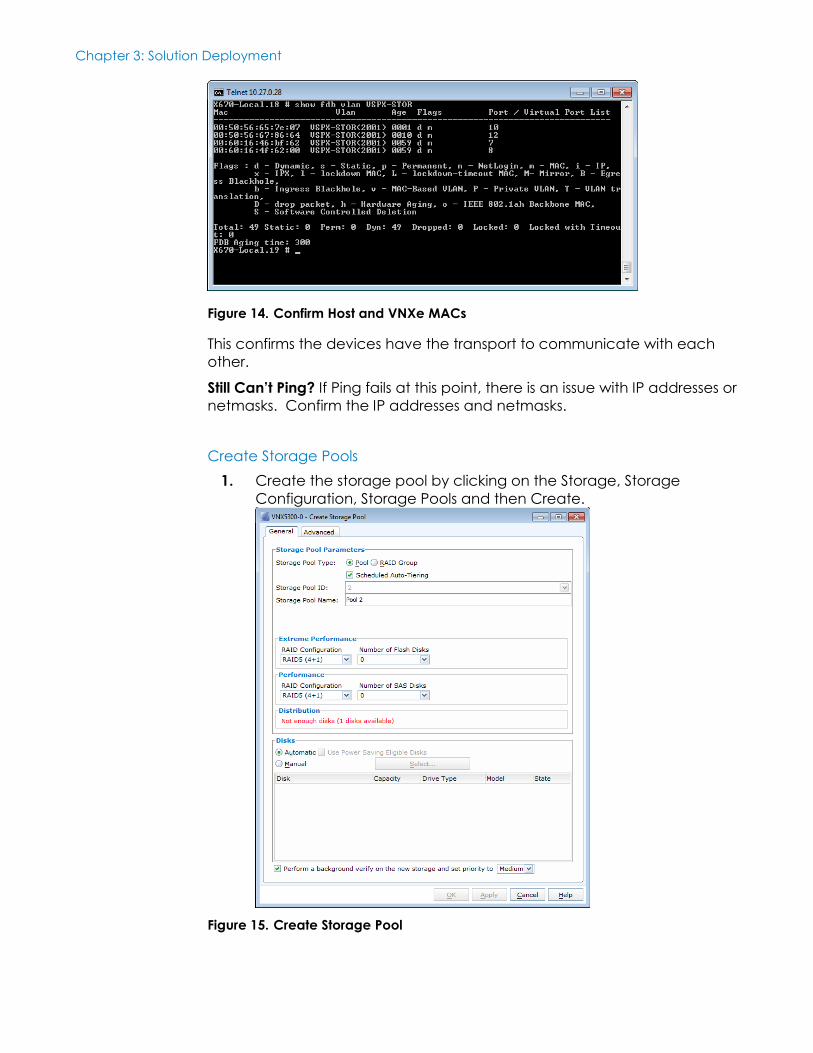
show fdb vlan VSPX-STOR
Chapter 3: Solution Deployment
44 <Document Title>
<Document Type>
Figure 14. Confirm Host and VNXe MACs
This confirms the devices have the transport to communicate with each
other.
Still Can’t Ping? If Ping fails at this point, there is an issue with IP addresses or
netmasks. Confirm the IP addresses and netmasks.
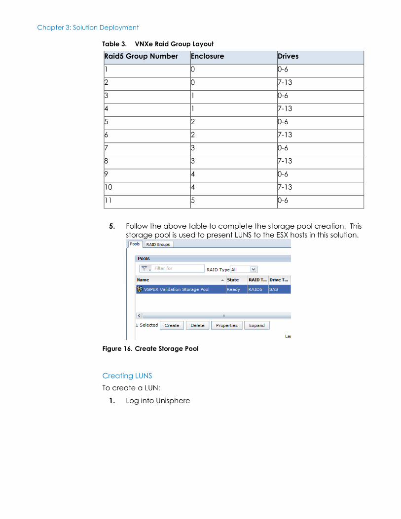
Create Storage Pools
1. Create the storage pool by clicking on the Storage, Storage
Configuration, Storage Pools and then Create.
Figure 15. Create Storage Pool

Chapter 3: Solution Deployment
45 <Document Title>
<Document Type>
2. Select Pool for Storage Pool Type, Tick Scheduled Auto-Tiering, and
then enter a Storage Pool Name.
3. Select Raid5 (6+1)
4. Tick Manual, then click Select. Drives as follows:
Chapter 3: Solution Deployment
46 <Document Title>
<Document Type>
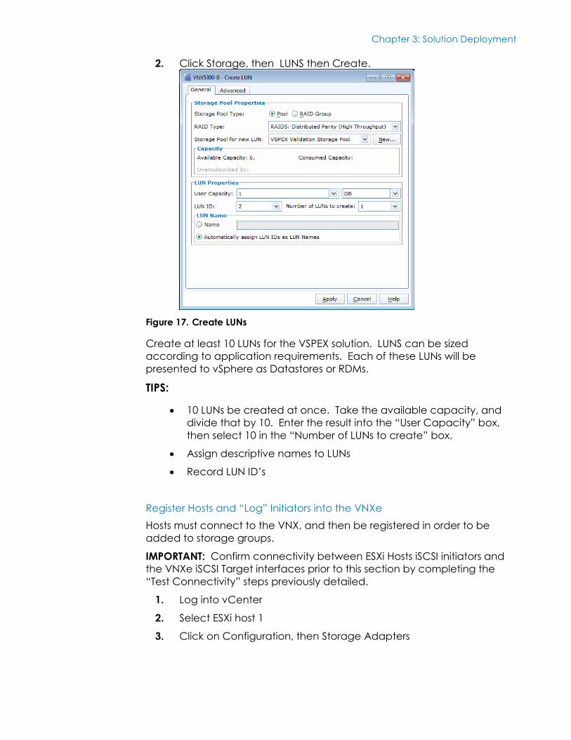
Table 3. VNXe Raid Group Layout
Raid5 Group Number Enclosure Drives
1 0 0-6
2 0 7-13
3 1 0-6
4 1 7-13
5 2 0-6
6 2 7-13
7 3 0-6
8 3 7-13
9 4 0-6
10 4 7-13
11 5 0-6
5. Follow the above table to complete the storage pool creation. This
storage pool is used to present LUNS to the ESX hosts in this solution.
Figure 16. Create Storage Pool
Creating LUNS
To create a LUN:
1. Log into Unisphere
Chapter 3: Solution Deployment
47 <Document Title>
<Document Type>
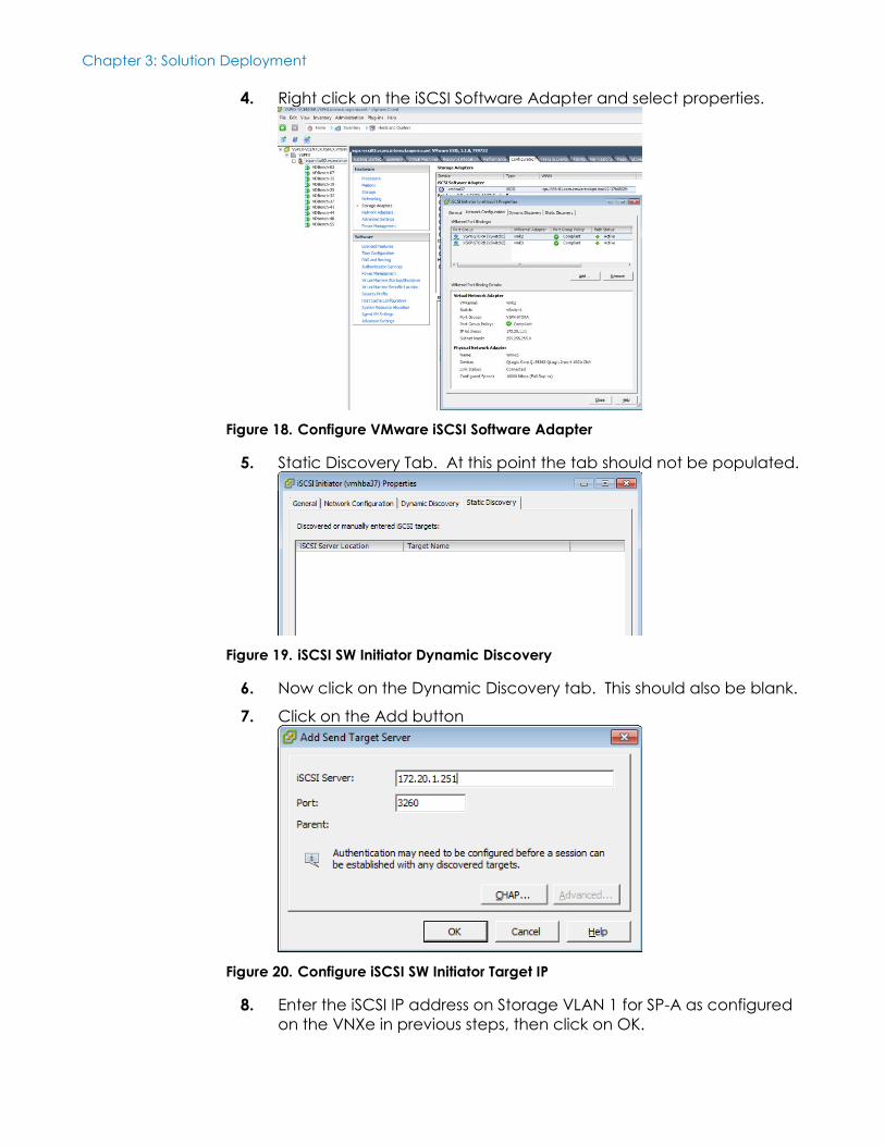
2. Click Storage, then LUNS then Create.
Figure 17. Create LUNs
Create at least 10 LUNs for the VSPEX solution. LUNS can be sized
according to application requirements. Each of these LUNs will be
presented to vSphere as Datastores or RDMs.
TIPS:
10 LUNs be created at once. Take the available capacity, and
divide that by 10. Enter the result into the “User Capacity” box,
then select 10 in the “Number of LUNs to create” box.
Assign descriptive names to LUNs
Record LUN ID’s
Register Hosts and “Log” Initiators into the VNXe
Hosts must connect to the VNX, and then be registered in order to be
added to storage groups.
IMPORTANT: Confirm connectivity between ESXi Hosts iSCSI initiators and
the VNXe iSCSI Target interfaces prior to this section by completing the
“Test Connectivity” steps previously detailed.
1. Log into vCenter
2. Select ESXi host 1
3. Click on Configuration, then Storage Adapters
Chapter 3: Solution Deployment
48 <Document Title>
<Document Type>
4. Right click on the iSCSI Software Adapter and select properties.
Figure 18. Configure VMware iSCSI Software Adapter
5. Static Discovery Tab. At this point the tab should not be populated.
Figure 19. iSCSI SW Initiator Dynamic Discovery
6. Now click on the Dynamic Discovery tab. This should also be blank.
7. Click on the Add button
Figure 20. Configure iSCSI SW Initiator Target IP
8. Enter the iSCSI IP address on Storage VLAN 1 for SP-A as configured
on the VNXe in previous steps, then click on OK.
Chapter 3: Solution Deployment
49 <Document Title>
<Document Type>
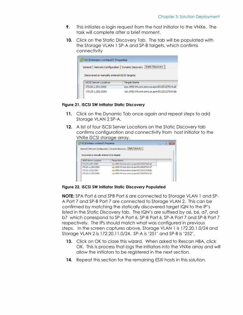
9. This initiates a login request from the host initiator to the VNXe. The
task will complete after a brief moment.
10. Click on the Static Discovery Tab. The tab will be populated with
the Storage VLAN 1 SP-A and SP-B targets, which confirms
connectivity
.
Figure 21. iSCSI SW Initiator Static Discovery
11. Click on the Dynamic Tab once again and repeat steps to add
Storage VLAN 2 SP-A.
12. A list of four iSCSI Server Locations on the Static Discovery tab
confirms configuration and connectivity from host initiator to the
VNXe iSCSI storage array.
Figure 22. iSCSI SW Initiator Static Discovery Populated
NOTE: SPA Port 6 and SPB Port 6 are connected to Storage VLAN 1 and SP-
A Port 7 and SP-B Port 7 are connected to Storage VLAN 2. This can be
confirmed by matching the statically discovered target IQN to the IP’s
listed in the Static Discovery tab. The IQN’s are suffixed by a6, b6, a7, and
b7 which correspond to SP-A Port 6, SP-B Port 6, SP-A Port 7 and SP-B Port 7
respectively. The IPs should match what was configured in previous
steps. In the screen captures above, Storage VLAN 1 is 172.20.1.0/24 and
Storage VLAN 2 is 172.20.11.0/24. SP-A is ‘251’ and SP-B is ‘252’.
13. Click on OK to close this wizard. When asked to Rescan HBA, click
OK. This is process that logs the initiators into the VNXe array and will
allow the initiators to be registered in the next section.
14. Repeat this section for the remaining ESXi hosts in this solution.
Chapter 3: Solution Deployment
50 <Document Title>
<Document Type>
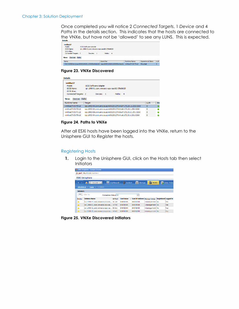
Once completed you will notice 2 Connected Targets, 1 Device and 4
Paths in the details section. This indicates that the hosts are connected to
the VNXe, but have not be ‘allowed’ to see any LUNS. This is expected.
Figure 23. VNXe Discovered
Figure 24. Paths to VNXe
After all ESXi hosts have been logged into the VNXe, return to the
Unisphere GUI to Register the hosts.
Registering Hosts
1. Login to the Unisphere GUI, click on the Hosts tab then select
Initiators
Figure 25. VNXe Discovered Initiators
Chapter 3: Solution Deployment
51 <Document Title>
<Document Type>
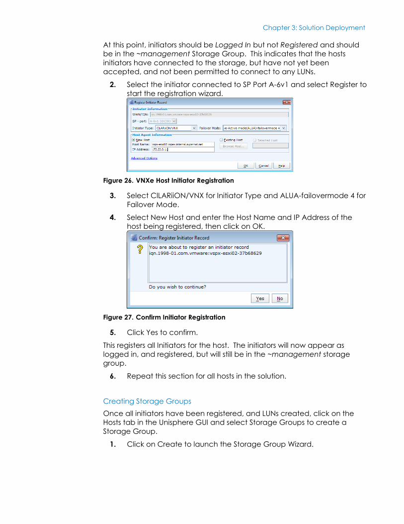
At this point, initiators should be Logged In but not Registered and should
be in the ~management Storage Group. This indicates that the hosts
initiators have connected to the storage, but have not yet been
accepted, and not been permitted to connect to any LUNs.
2. Select the initiator connected to SP Port A-6v1 and select Register to
start the registration wizard.
Figure 26. VNXe Host Initiator Registration
3. Select ClLARiiON/VNX for Initiator Type and ALUA-failovermode 4 for
Failover Mode.
4. Select New Host and enter the Host Name and IP Address of the
host being registered, then click on OK.
Figure 27. Confirm Initiator Registration
5. Click Yes to confirm.
This registers all Initiators for the host. The initiators will now appear as
logged in, and registered, but will still be in the ~management storage
group.
6. Repeat this section for all hosts in the solution.
Creating Storage Groups
Once all initiators have been registered, and LUNs created, click on the
Hosts tab in the Unisphere GUI and select Storage Groups to create a
Storage Group.
1. Click on Create to launch the Storage Group Wizard.
Chapter 3: Solution Deployment
52 <Document Title>
<Document Type>
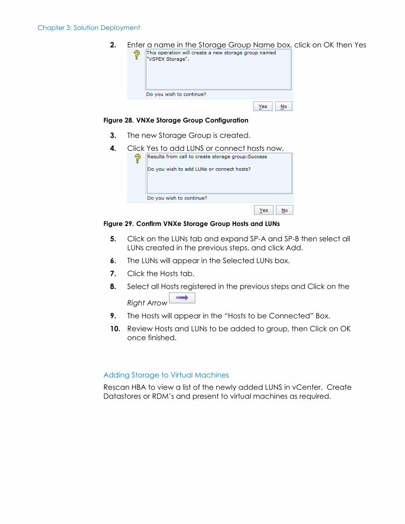
2. Enter a name in the Storage Group Name box, click on OK then Yes
Figure 28. VNXe Storage Group Configuration
3. The new Storage Group is created.
4. Click Yes to add LUNS or connect hosts now.
Figure 29. Confirm VNXe Storage Group Hosts and LUNs
5. Click on the LUNs tab and expand SP-A and SP-B then select all
LUNs created in the previous steps, and click Add.
6. The LUNs will appear in the Selected LUNs box.
7. Click the Hosts tab.
8. Select all Hosts registered in the previous steps and Click on the
Right Arrow
9. The Hosts will appear in the “Hosts to be Connected” Box.
10. Review Hosts and LUNs to be added to group, then Click on OK
once finished.
Adding Storage to Virtual Machines
Rescan HBA to view a list of the newly added LUNS in vCenter. Create
Datastores or RDM’s and present to virtual machines as required.

Chapter 4: Acknowledgements
53 <Document Title>
<Document Type>
Chapter 4 Acknowledgements
This chapter presents the following topic:
Acknowledgements ............................................................................................. 54

Chapter 4: Acknowledgements
54 <Document Title>
<Document Type>
Acknowledgements
The Lenovo ThinkServer - EMC VSPEX Private Cloud solution for VMware
vSphere 5.1 was independently validated at Superna
(http://www.superna.net).

Chapter 5: References
55 <Document Title>
<Document Type>
Chapter 5 References
This chapter presents the following topic:
References ............................................................................................................ 56
Chapter 5: References
56 <Document Title>
<Document Type>
References
VSPEX Solution References:
EMC VSPEX Private Cloud Proven Infrastructure Guide
http://www.emc.com/collateral/technical-documentation/h11553-vspex-pi-pc-vmware-vnx.pdf
Lenovo Thinkserver – EMC VSPEX Private Cloud Validated Reference Architecture
<insert link to published Lenovo VSPEX Solution Reference Architecture document>
Extreme Summit References:
Legacy CLI Quick Reference Guide
http://www.extremenetworks.com/libraries/services/Legacy_CLI_Quick_Reference_Guide.pdf
ExtremeXOS ScreenPlay User Guide
http://www.extremenetworks.com/libraries/services/ExtremeXOS_ScreenPlay.pdf
ExtremeXOS® Concepts Guide Software Version 15.1
http://www.extremenetworks.com/libraries/services/EXOSConcepts_15.1_Version4.pdf
Summit® Family Switches Hardware Installation Guide
http://www.extremenetworks.com/libraries/services/100286-00_Rev18_InstallGuide.pdf
Lenovo ThinkServer References:
ThinkServer User Guide
http://download.lenovo.com/ibmdl/pub/pc/pccbbs/thinkservers/rd630ug_en.pdf
ThinkServer Management Module (TMM) and iKVM Guide
Chapter 5: References
57 <Document Title>
<Document Type>
http://download.lenovo.com/ibmdl/pub/pc/pccbbs/thinkservers/rd530rd630tmmug_en.pdf
VMWare References:
vSphere Installation and Setup
http://pubs.vmware.com/vsphere-51/topic/com.vmware.ICbase/PDF/vsphere-esxi-vcenter-server-51-installation-setup-guide.pdf
EMC VNX References:
EMC® VNX™ VNXe3300™ Installation Guide
https://support.emc.com/docu31489_VNXe3300-Installation-Guide.pdf?language=en_US
EMC® VNXe™3300 System Hardware Installation Guide for Telco Racks
https://support.emc.com/docu34546_VNXe3300-Enclosures-Hardware-Installation-Guide-for-Telco-Racks.pdf?language=en_US
EMC® VNXe™ Series: Using a VNXe System with VMware NFS or VMware
VMFS
https://support.emc.com/docu31486_VNXe-Series-Using-a-VNXe-System-with-VMware.pdf?language=en_US

Appendix A: VLAN and IP Address Schema
58 <Document Title>
<Document Type>
Appendix A VLAN and IP Address Schema
This appendix presents the following topic:
VLAN and IP Address Schema ............................................................................ 59
Appendix A: VLAN and IP Address Schema
59 <Document Title>
<Document Type>
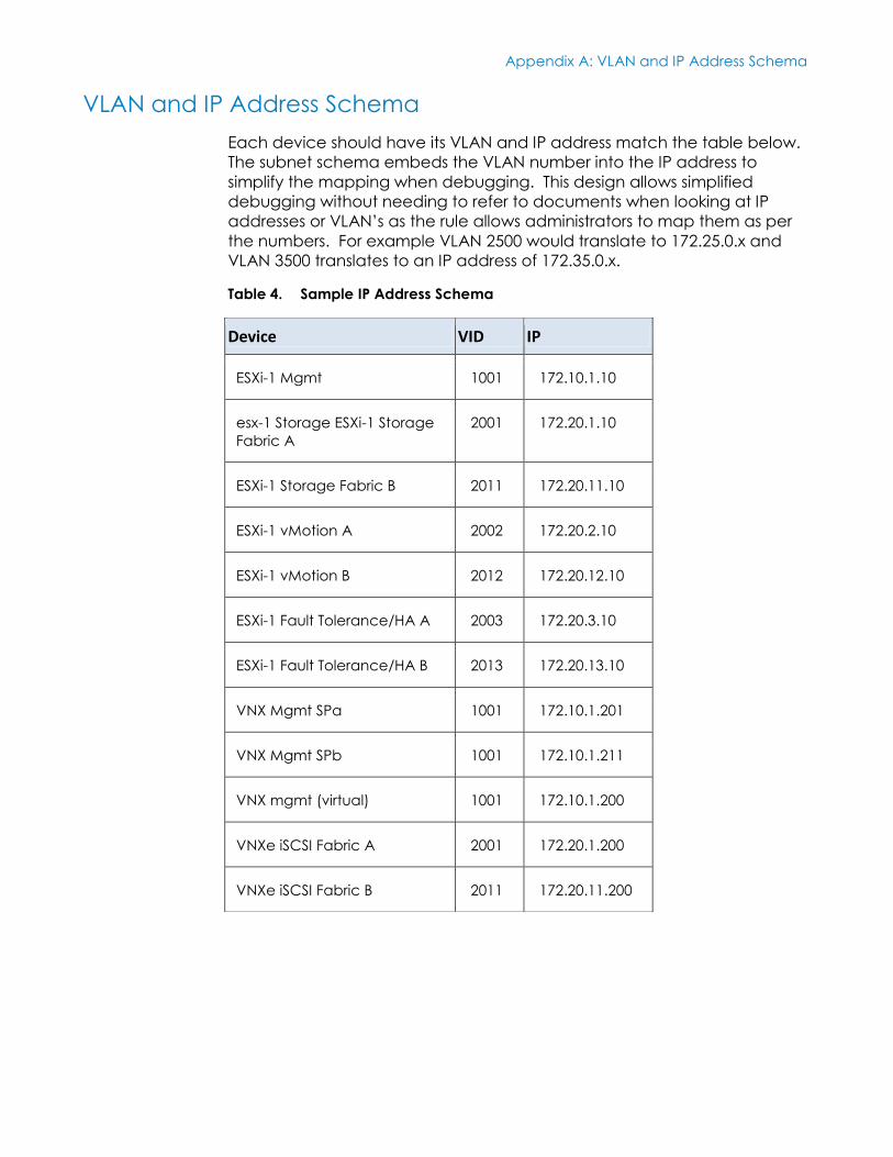
VLAN and IP Address Schema
Each device should have its VLAN and IP address match the table below.
The subnet schema embeds the VLAN number into the IP address to
simplify the mapping when debugging. This design allows simplified
debugging without needing to refer to documents when looking at IP
addresses or VLAN’s as the rule allows administrators to map them as per
the numbers. For example VLAN 2500 would translate to 172.25.0.x and
VLAN 3500 translates to an IP address of 172.35.0.x.
Table 4. Sample IP Address Schema
Device VID IP
ESXi-1 Mgmt 1001 172.10.1.10
esx-1 Storage ESXi-1 Storage
Fabric A
2001 172.20.1.10
ESXi-1 Storage Fabric B 2011 172.20.11.10
ESXi-1 vMotion A 2002 172.20.2.10
ESXi-1 vMotion B 2012 172.20.12.10
ESXi-1 Fault Tolerance/HA A 2003 172.20.3.10
ESXi-1 Fault Tolerance/HA B 2013 172.20.13.10
VNX Mgmt SPa 1001 172.10.1.201
VNX Mgmt SPb 1001 172.10.1.211
VNX mgmt (virtual) 1001 172.10.1.200
VNXe iSCSI Fabric A 2001 172.20.1.200
VNXe iSCSI Fabric B 2011 172.20.11.200
Appendix B: Compute Card Schema
60 <Document Title>
<Document Type>
Appendix B Compute Card Schema
This appendix presents the following topic:
CNA Network Assignments .................................................................................. 61
Appendix B: Compute Card Schema
61 <Document Title>
<Document Type>
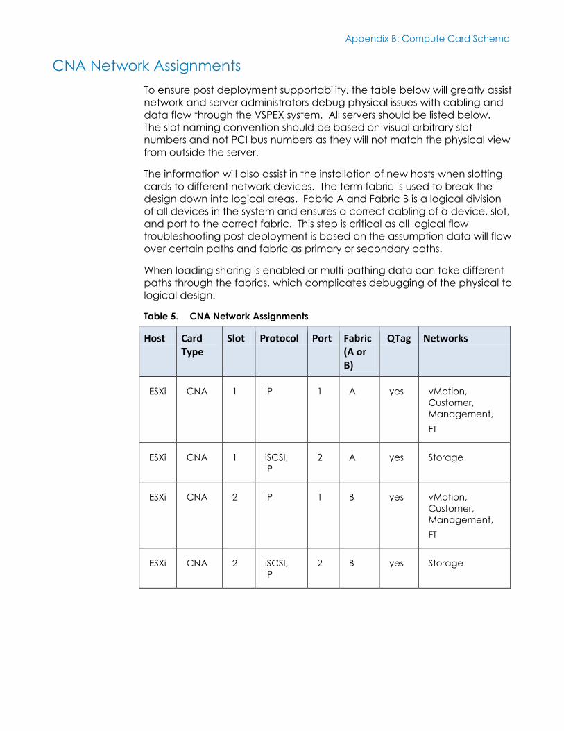
CNA Network Assignments
To ensure post deployment supportability, the table below will greatly assist
network and server administrators debug physical issues with cabling and
data flow through the VSPEX system. All servers should be listed below.
The slot naming convention should be based on visual arbitrary slot
numbers and not PCI bus numbers as they will not match the physical view
from outside the server.
The information will also assist in the installation of new hosts when slotting
cards to different network devices. The term fabric is used to break the
design down into logical areas. Fabric A and Fabric B is a logical division
of all devices in the system and ensures a correct cabling of a device, slot,
and port to the correct fabric. This step is critical as all logical flow
troubleshooting post deployment is based on the assumption data will flow
over certain paths and fabric as primary or secondary paths.
When loading sharing is enabled or multi-pathing data can take different
paths through the fabrics, which complicates debugging of the physical to
logical design.
Table 5. CNA Network Assignments
Host Card Type
Slot Protocol Port Fabric (A or B)
QTag Networks
ESXi CNA 1 IP 1 A yes vMotion,
Customer,
Management,
FT
ESXi CNA 1 iSCSI,
IP
2 A yes Storage
ESXi CNA 2 IP 1 B yes vMotion,
Customer,
Management,
FT
ESXi CNA 2 iSCSI,
IP
2 B yes Storage
Appendix C: Sample Network Configuration
62 <Document Title>
<Document Type>
Appendix C Sample Network Configuration
This appendix presents the following topic:
Sample Network Configuration .......................................................................... 63
Appendix C: Sample Network Configuration
63 <Document Title>
<Document Type>
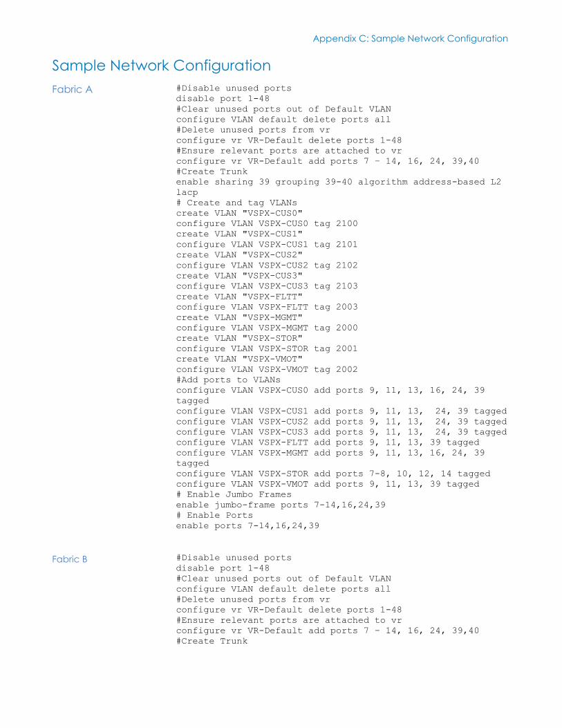
Sample Network Configuration
#Disable unused ports
disable port 1-48
#Clear unused ports out of Default VLAN
configure VLAN default delete ports all
#Delete unused ports from vr
configure vr VR-Default delete ports 1-48
#Ensure relevant ports are attached to vr
configure vr VR-Default add ports 7 – 14, 16, 24, 39,40
#Create Trunk
enable sharing 39 grouping 39-40 algorithm address-based L2
lacp
# Create and tag VLANs
create VLAN "VSPX-CUS0"
configure VLAN VSPX-CUS0 tag 2100
create VLAN "VSPX-CUS1"
configure VLAN VSPX-CUS1 tag 2101
create VLAN "VSPX-CUS2"
configure VLAN VSPX-CUS2 tag 2102
create VLAN "VSPX-CUS3"
configure VLAN VSPX-CUS3 tag 2103
create VLAN "VSPX-FLTT"
configure VLAN VSPX-FLTT tag 2003
create VLAN "VSPX-MGMT"
configure VLAN VSPX-MGMT tag 2000
create VLAN "VSPX-STOR"
configure VLAN VSPX-STOR tag 2001
create VLAN "VSPX-VMOT"
configure VLAN VSPX-VMOT tag 2002
#Add ports to VLANs
configure VLAN VSPX-CUS0 add ports 9, 11, 13, 16, 24, 39
tagged
configure VLAN VSPX-CUS1 add ports 9, 11, 13, 24, 39 tagged
configure VLAN VSPX-CUS2 add ports 9, 11, 13, 24, 39 tagged
configure VLAN VSPX-CUS3 add ports 9, 11, 13, 24, 39 tagged
configure VLAN VSPX-FLTT add ports 9, 11, 13, 39 tagged
configure VLAN VSPX-MGMT add ports 9, 11, 13, 16, 24, 39
tagged
configure VLAN VSPX-STOR add ports 7-8, 10, 12, 14 tagged
configure VLAN VSPX-VMOT add ports 9, 11, 13, 39 tagged
# Enable Jumbo Frames
enable jumbo-frame ports 7-14,16,24,39
# Enable Ports
enable ports 7-14,16,24,39
#Disable unused ports
disable port 1-48
#Clear unused ports out of Default VLAN
configure VLAN default delete ports all
#Delete unused ports from vr
configure vr VR-Default delete ports 1-48
#Ensure relevant ports are attached to vr
configure vr VR-Default add ports 7 – 14, 16, 24, 39,40
#Create Trunk
Fabric A
Fabric B
Appendix C: Sample Network Configuration
64 <Document Title>
<Document Type>
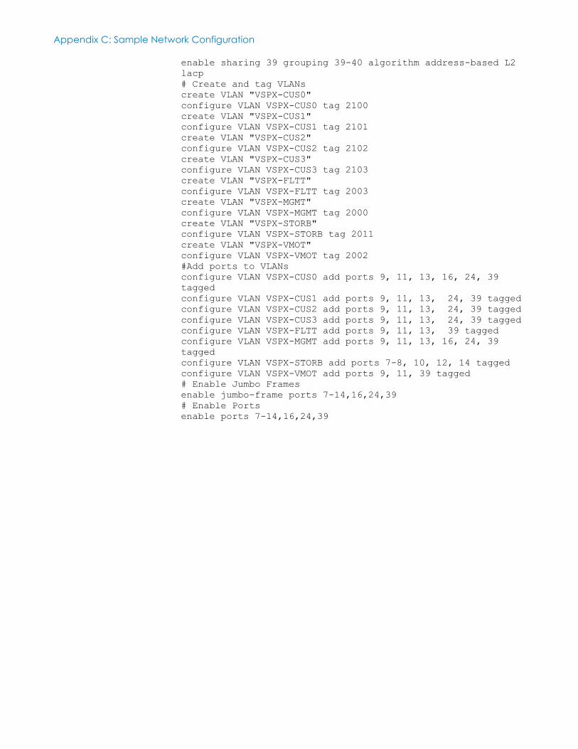
enable sharing 39 grouping 39-40 algorithm address-based L2
lacp
# Create and tag VLANs
create VLAN "VSPX-CUS0"
configure VLAN VSPX-CUS0 tag 2100
create VLAN "VSPX-CUS1"
configure VLAN VSPX-CUS1 tag 2101
create VLAN "VSPX-CUS2"
configure VLAN VSPX-CUS2 tag 2102
create VLAN "VSPX-CUS3"
configure VLAN VSPX-CUS3 tag 2103
create VLAN "VSPX-FLTT"
configure VLAN VSPX-FLTT tag 2003
create VLAN "VSPX-MGMT"
configure VLAN VSPX-MGMT tag 2000
create VLAN "VSPX-STORB"
configure VLAN VSPX-STORB tag 2011
create VLAN "VSPX-VMOT"
configure VLAN VSPX-VMOT tag 2002
#Add ports to VLANs
configure VLAN VSPX-CUS0 add ports 9, 11, 13, 16, 24, 39
tagged
configure VLAN VSPX-CUS1 add ports 9, 11, 13, 24, 39 tagged
configure VLAN VSPX-CUS2 add ports 9, 11, 13, 24, 39 tagged
configure VLAN VSPX-CUS3 add ports 9, 11, 13, 24, 39 tagged
configure VLAN VSPX-FLTT add ports 9, 11, 13, 39 tagged
configure VLAN VSPX-MGMT add ports 9, 11, 13, 16, 24, 39
tagged
configure VLAN VSPX-STORB add ports 7-8, 10, 12, 14 tagged
configure VLAN VSPX-VMOT add ports 9, 11, 39 tagged
# Enable Jumbo Frames
enable jumbo-frame ports 7-14,16,24,39
# Enable Ports
enable ports 7-14,16,24,39

Appendix D: Sample Cabling Guide
65 <Document Title>
<Document Type>
Appendix D Sample Cabling Guide
This appendix presents the following topic:
Sample Cabling Guide ........................................................................................ 66
Appendix D: Sample Cabling Guide
66 <Document Title>
<Document Type>
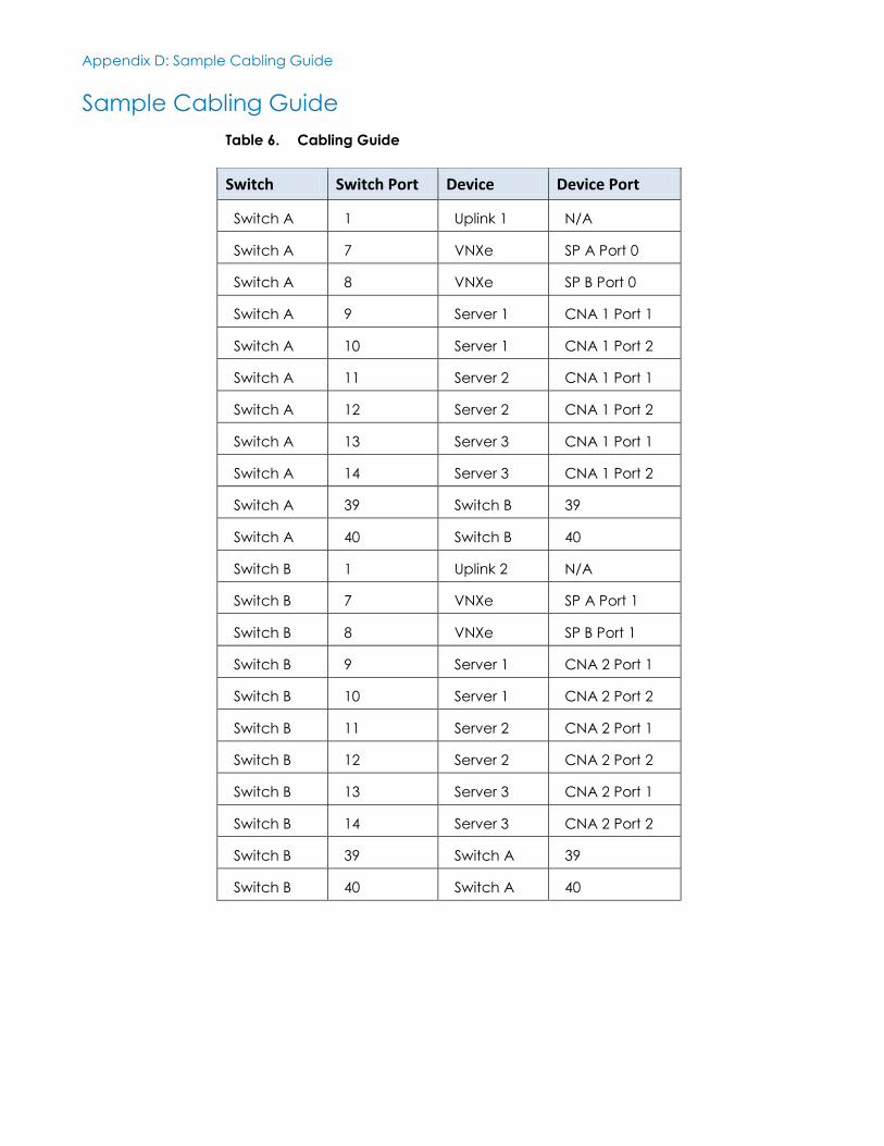
Sample Cabling Guide
Table 6. Cabling Guide
Switch Switch Port Device Device Port
Switch A 1 Uplink 1 N/A
Switch A 7 VNXe SP A Port 0
Switch A 8 VNXe SP B Port 0
Switch A 9 Server 1 CNA 1 Port 1
Switch A 10 Server 1 CNA 1 Port 2
Switch A 11 Server 2 CNA 1 Port 1
Switch A 12 Server 2 CNA 1 Port 2
Switch A 13 Server 3 CNA 1 Port 1
Switch A 14 Server 3 CNA 1 Port 2
Switch A 39 Switch B 39
Switch A 40 Switch B 40
Switch B 1 Uplink 2 N/A
Switch B 7 VNXe SP A Port 1
Switch B 8 VNXe SP B Port 1
Switch B 9 Server 1 CNA 2 Port 1
Switch B 10 Server 1 CNA 2 Port 2
Switch B 11 Server 2 CNA 2 Port 1
Switch B 12 Server 2 CNA 2 Port 2
Switch B 13 Server 3 CNA 2 Port 1
Switch B 14 Server 3 CNA 2 Port 2
Switch B 39 Switch A 39
Switch B 40 Switch A 40
Appendix E: Sample Switch Port Labeling Guide
67 <Document Title>
<Document Type>
Appendix E Sample Switch Port Labeling
Guide
This appendix presents the following topic:
Sample Switch Port Labeling Guide .................................................................. 68
Appendix E: Sample Switch Port Labeling Guide
68 <Document Title>
<Document Type>
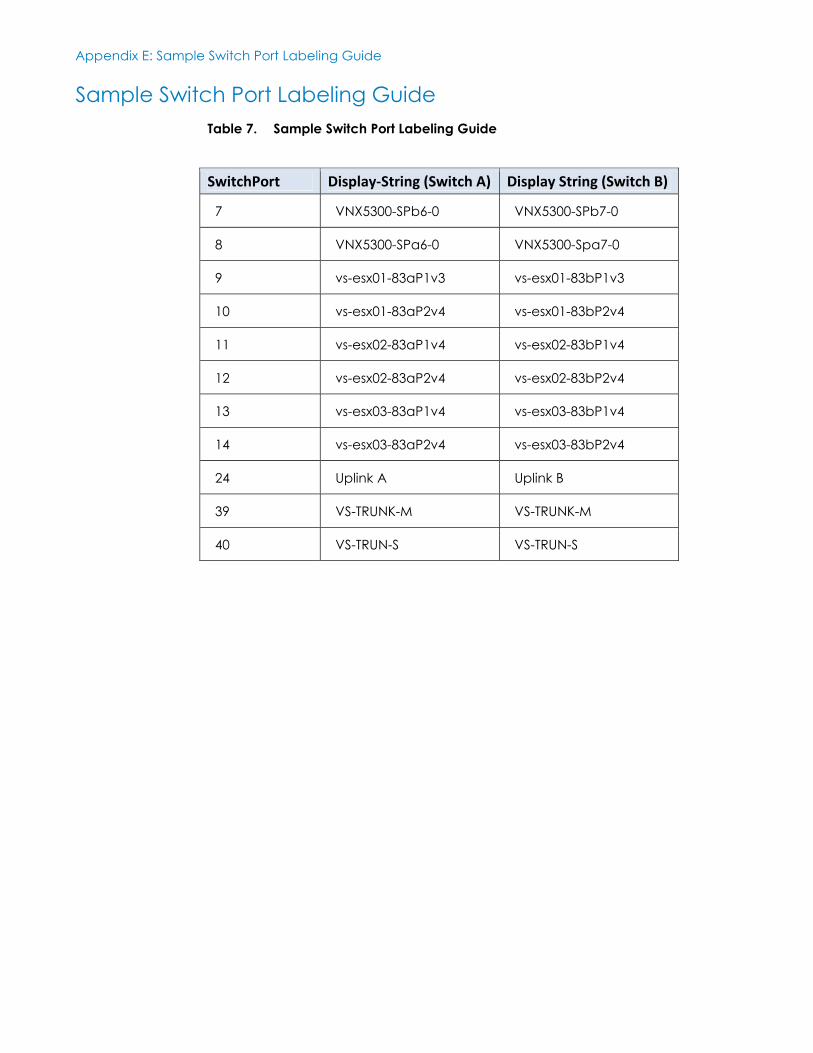
Sample Switch Port Labeling Guide
Table 7. Sample Switch Port Labeling Guide
SwitchPort Display-String (Switch A) Display String (Switch B)
7 VNX5300-SPb6-0 VNX5300-SPb7-0
8 VNX5300-SPa6-0 VNX5300-Spa7-0
9 vs-esx01-83aP1v3 vs-esx01-83bP1v3
10 vs-esx01-83aP2v4 vs-esx01-83bP2v4
11 vs-esx02-83aP1v4 vs-esx02-83bP1v4
12 vs-esx02-83aP2v4 vs-esx02-83bP2v4
13 vs-esx03-83aP1v4 vs-esx03-83bP1v4
14 vs-esx03-83aP2v4 vs-esx03-83bP2v4
24 Uplink A Uplink B
39 VS-TRUNK-M VS-TRUNK-M
40 VS-TRUN-S VS-TRUN-S
Appendix F: Compute Firmware and Hardware Installation
69 <Document Title>
<Document Type>
Appendix F Compute Firmware and
Hardware Installation
This appendix presents the following topics:
PCIe Slot Assignment ............................................................................................ 70
Recommended Firmware Release (TBC) .......................................................... 70
Appendix F: Compute Firmware and Hardware Installation
70 <Document Title>
<Document Type>
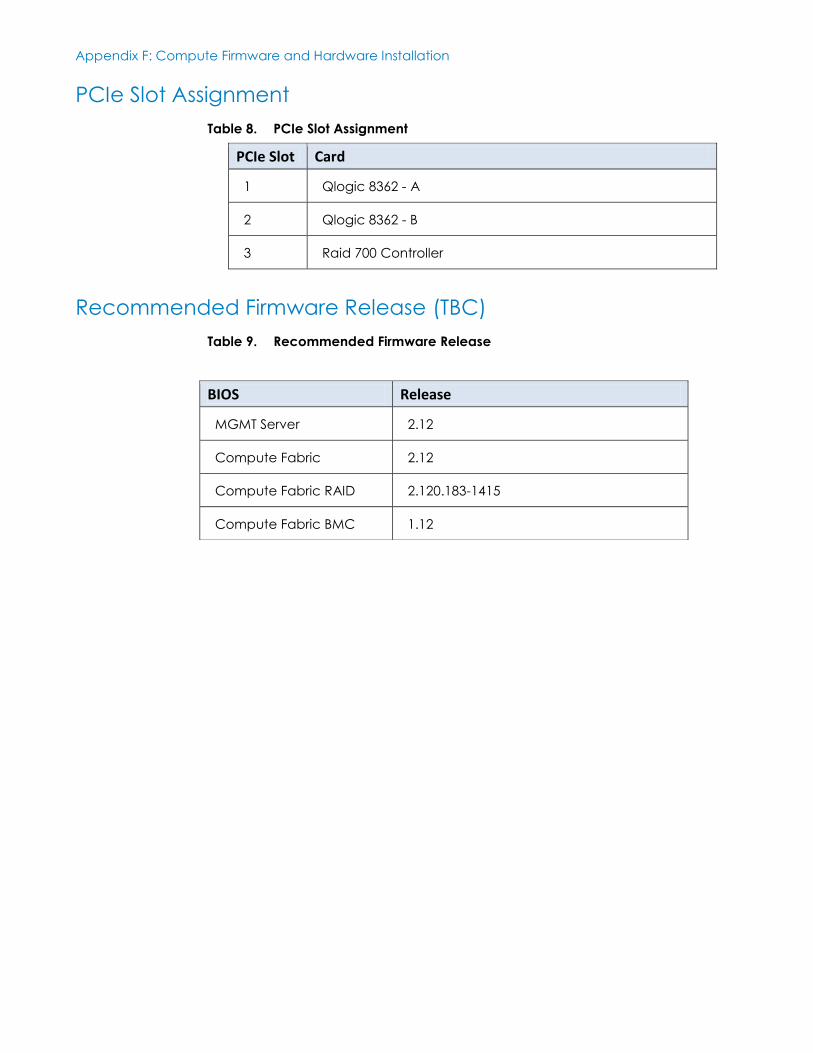
PCIe Slot Assignment
Table 8. PCIe Slot Assignment
PCIe Slot Card
1 Qlogic 8362 - A
2 Qlogic 8362 - B
3 Raid 700 Controller
Recommended Firmware Release (TBC)
Table 9. Recommended Firmware Release
BIOS Release
MGMT Server 2.12
Compute Fabric 2.12
Compute Fabric RAID 2.120.183-1415
Compute Fabric BMC 1.12

Appendix G: Power and Rack Position Planning
71 <Document Title>
<Document Type>
Appendix G Power and Rack Position
Planning
This appendix presents the following topic:
Power and Rack Position Planning..................................................................... 72
Appendix G: Power and Rack Position Planning
72 <Document Title>
<Document Type>
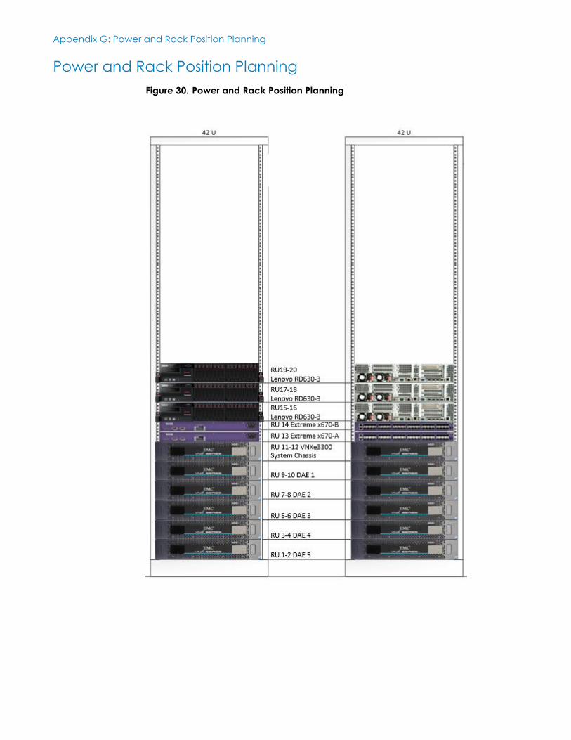
Power and Rack Position Planning
Figure 30. Power and Rack Position Planning
Recommended