The impact of valley geometry on thermallydriven flows and vertical heat fluxes
Johannes Wagner, Alexander Gohm, Mathias Rotach,Daniel Leukauf, Christian Posch
Institute of Meteorology and GeophysicsUniversity of Innsbruck, Austria
International Conference on Alpine Meteorology 2013
June 04, 2013
Outline
1 Introduction
2 Goals
3 Simulation results
4 Conclusion
Valley geometry and thermally driven flowsICAM 2013 2/18
Outline
1 Introduction
2 Goals
3 Simulation results
4 Conclusion
Valley geometry and thermally driven flowsICAM 2013 3/18
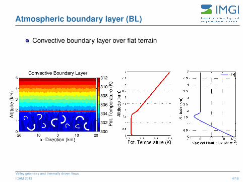
Atmospheric boundary layer (BL)
Convective boundary layer over flat terrain
Valley geometry and thermally driven flowsICAM 2013 4/18
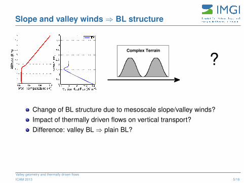
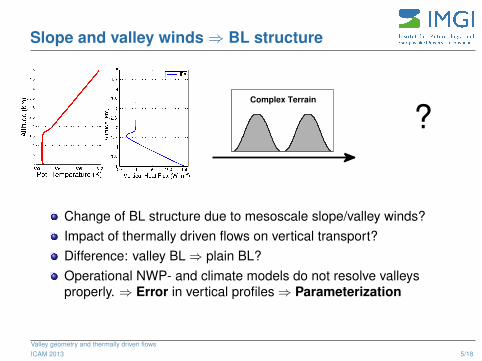
Slope and valley winds ⇒ BL structure
Complex Terrain
?
Change of BL structure due to mesoscale slope/valley winds?Impact of thermally driven flows on vertical transport?Difference: valley BL ⇒ plain BL?
Valley geometry and thermally driven flowsICAM 2013 5/18
Slope and valley winds ⇒ BL structure
Complex Terrain
?
Change of BL structure due to mesoscale slope/valley winds?Impact of thermally driven flows on vertical transport?Difference: valley BL ⇒ plain BL?Operational NWP- and climate models do not resolve valleysproperly. ⇒ Error in vertical profiles ⇒ Parameterization
Valley geometry and thermally driven flowsICAM 2013 5/18
Outline
1 Introduction
2 Goals
3 Simulation results
4 Conclusion
Valley geometry and thermally driven flowsICAM 2013 6/18
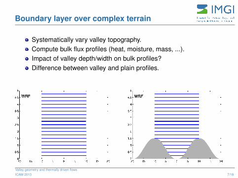
Boundary layer over complex terrain
Systematically vary valley topography.Compute bulk flux profiles (heat, moisture, mass, ...).Impact of valley depth/width on bulk profiles?Difference between valley and plain profiles.
Valley geometry and thermally driven flowsICAM 2013 7/18
Outline
1 Introduction
2 Goals
3 Simulation results
4 Conclusion
Valley geometry and thermally driven flowsICAM 2013 8/18
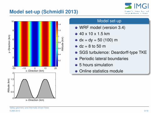
Model set-up (Schmidli 2013)
x−Direction (km)
y−
Direction (
km
)
−20 −10 0 10 200
2
4
6
8
10
Altitude (
km
)
x−Direction (km)0
0.5
1
1.5
2
Altitude (
km
)0.2
0.4
0.6
0.8
1
1.2
1.4
Model set-up
WRF model (version 3.4)40 x 10 x 1.5 kmdx = dy = 50 (100) mdz = 8 to 50 mSGS turbulence: Deardorff-type TKEPeriodic lateral boundaries5 hours simulationOnline statistics module
Valley geometry and thermally driven flowsICAM 2013 9/18
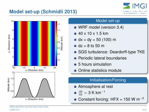
Model set-up (Schmidli 2013)
x−Direction (km)
y−
Direction (
km
)
−20 −10 0 10 200
2
4
6
8
10
Altitude (
km
)
x−Direction (km)0
0.5
1
1.5
2
Altitude (
km
)0.2
0.4
0.6
0.8
1
1.2
1.4
Model set-up
WRF model (version 3.4)40 x 10 x 1.5 kmdx = dy = 50 (100) mdz = 8 to 50 mSGS turbulence: Deardorff-type TKEPeriodic lateral boundaries5 hours simulationOnline statistics module
Initialisation/Forcing
Atmosphere at rest∂θ∂z = 3 K km−1
Constant forcing: HFX = 150 W m−2
Valley geometry and thermally driven flowsICAM 2013 9/18
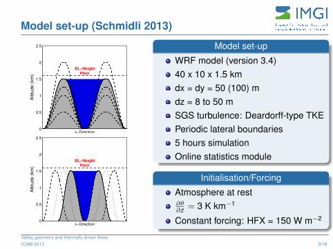
Model set-up (Schmidli 2013)A
ltitu
de
(km
)
x−Direction
BL−HeightPlain
0
0.5
1
1.5
2
2.5
x−Direction
Altitu
de
(km
)
BL−HeightPlain
0
0.5
1
1.5
2
2.5
Model set-up
WRF model (version 3.4)40 x 10 x 1.5 kmdx = dy = 50 (100) mdz = 8 to 50 mSGS turbulence: Deardorff-type TKEPeriodic lateral boundaries5 hours simulationOnline statistics module
Initialisation/Forcing
Atmosphere at rest∂θ∂z = 3 K km−1
Constant forcing: HFX = 150 W m−2
Valley geometry and thermally driven flowsICAM 2013 9/18
LES Output
Valley geometry and thermally driven flowsICAM 2013 10/18
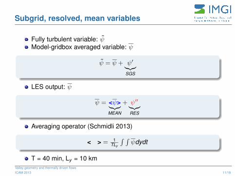
Subgrid, resolved, mean variables
Fully turbulent variable: ψ̃Model-gridbox averaged variable: ψ
ψ̃ = ψ + ψ′︸︷︷︸SGS
LES output: ψ
ψ = <ψ>︸︷︷︸MEAN
+ ψ′′︸︷︷︸RES
Averaging operator (Schmidli 2013)
< > = 1TLy
∫ ∫ψdydt
T = 40 min, Ly = 10 kmValley geometry and thermally driven flowsICAM 2013 11/18
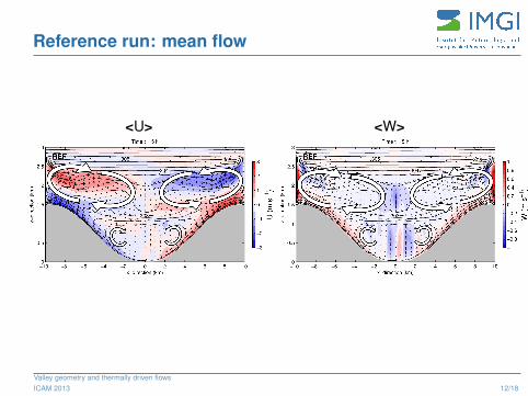
Reference run: mean flow
<U> <W>
Valley geometry and thermally driven flowsICAM 2013 12/18

Heat flux profile: plain ⇔ valley
MEAN+RES+SGS:
Vertical heat flux (W m−2
)
Altitu
de
(km
)
BULK HFX
−50 0 50 100 1500
0.5
1
1.5
2
2.5
3
MEAN
RES
SGS
TOT
x−direction (km)
z−
direction (
km
)
Time t = 5 h
303
REF
0 2 4 6 8 10 120
0.5
1
1.5
2
2.5
3
WP
TT
OT
(K
m s
−1)
−0.4
−0.3
−0.2
−0.1
0
0.1
0.2
0.3
0.4
Vertical heat flux (W m−2
)
Altitu
de
(km
)
BULK HFX
−50 0 50 100 1500
0.5
1
1.5
2
2.5
3
MEAN
RES
SGS
TOT
Valley geometry and thermally driven flowsICAM 2013 13/18
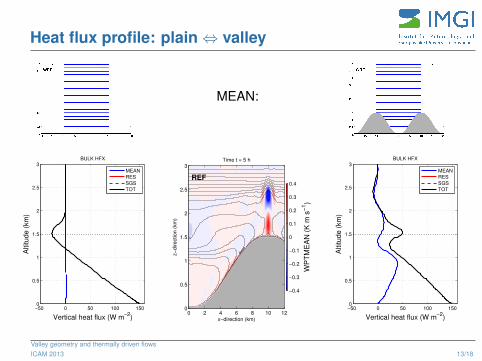
Heat flux profile: plain ⇔ valley
MEAN:
Vertical heat flux (W m−2
)
Altitu
de
(km
)
BULK HFX
−50 0 50 100 1500
0.5
1
1.5
2
2.5
3
MEAN
RES
SGS
TOT
x−direction (km)
z−
direction (
km
)
Time t = 5 h
303
REF
0 2 4 6 8 10 120
0.5
1
1.5
2
2.5
3
WP
TM
EA
N (
K m
s−
1)
−0.4
−0.3
−0.2
−0.1
0
0.1
0.2
0.3
0.4
Vertical heat flux (W m−2
)
Altitu
de
(km
)
BULK HFX
−50 0 50 100 1500
0.5
1
1.5
2
2.5
3
MEAN
RES
SGS
TOT
Valley geometry and thermally driven flowsICAM 2013 13/18
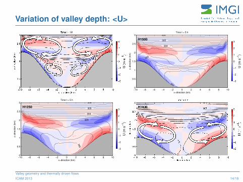
Variation of valley depth: <U>
x−direction (km)
z−
direction (
km
)
Time t = 5 h
302
303
303
304
305
306
H1250
−10 −8 −6 −4 −2 0 2 4 6 8 100
0.5
1
1.5
2
2.5
3
U (
m s
−1)
−3
−2
−1
0
1
2
3
x−direction (km)
z−
direction (
km
)
Time t = 5 h
302
303
303
304
305
306
H1500
−10 −8 −6 −4 −2 0 2 4 6 8 100
0.5
1
1.5
2
2.5
3
U (
m s
−1)
−3
−2
−1
0
1
2
3
Valley geometry and thermally driven flowsICAM 2013 14/18
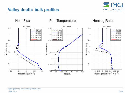
Valley depth: bulk profiles
Heat Flux
Heat flux (W m−2
)
Altitude (
km
)
BULK HFX
−50 0 50 100 1500
0.5
1
1.5
2
2.5
3
3.5
PLAIN
H0500
H1000
H1250
H1500
H2000
Pot. Temperature
Theta (K)
Altitu
de
(km
)
BULK Theta
300 301 302 303 304 305 3060
0.5
1
1.5
2
2.5
3
3.5
PLAIN
H0500
H1000
H1250
H1500
H2000
Heating Rate
Heating Rate (10−3
K s−1
)
Altitude (
km
)
BULK Tend
−0.1 −0.05 0 0.05 0.1 0.15 0.20
0.5
1
1.5
2
2.5
3
3.5
PLAIN
H0500
H1000
H1250
H1500
H2000
Valley geometry and thermally driven flowsICAM 2013 15/18
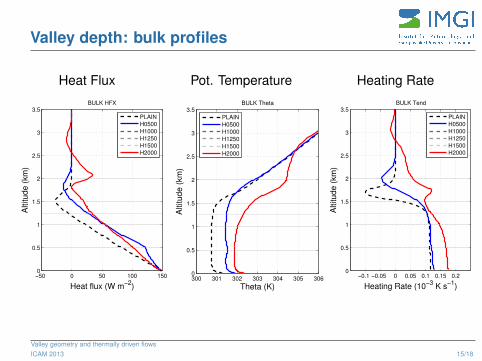
Outline
1 Introduction
2 Goals
3 Simulation results
4 Conclusion
Valley geometry and thermally driven flowsICAM 2013 16/18
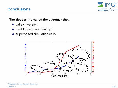
Conclusions
The deeper the valley the stronger the...valley inversionheat flux at mountain topsuperposed circulation cells
Valley geometry and thermally driven flowsICAM 2013 17/18
Conclusions
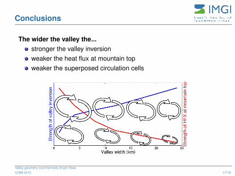
The wider the valley the...stronger the valley inversionweaker the heat flux at mountain topweaker the superposed circulation cells
Valley geometry and thermally driven flowsICAM 2013 17/18
Conclusions
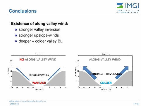
Existence of along valley wind:stronger valley inversionstronger upslope-windsdeeper + colder valley BL
Valley geometry and thermally driven flowsICAM 2013 17/18
Literature
Thank you for your attention!
Schmidli, J., 2013: Daytime heat transfer processes over mountainous terrain , sub.
Valley geometry and thermally driven flowsICAM 2013 18/18
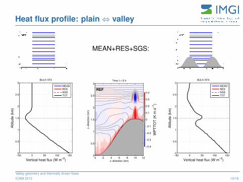
Heat flux profile: plain ⇔ valley
MEAN+RES+SGS:
Vertical heat flux (W m−2
)
Altitu
de
(km
)
BULK HFX
−50 0 50 100 1500
0.5
1
1.5
2
2.5
3
MEAN
RES
SGS
TOT
x−direction (km)
z−
direction (
km
)
Time t = 5 h
303
REF
0 2 4 6 8 10 120
0.5
1
1.5
2
2.5
3
WP
TT
OT
(K
m s
−1)
−0.4
−0.3
−0.2
−0.1
0
0.1
0.2
0.3
0.4
Vertical heat flux (W m−2
)
Altitu
de
(km
)
BULK HFX
−50 0 50 100 1500
0.5
1
1.5
2
2.5
3
MEAN
RES
SGS
TOT
Valley geometry and thermally driven flowsICAM 2013 19/18
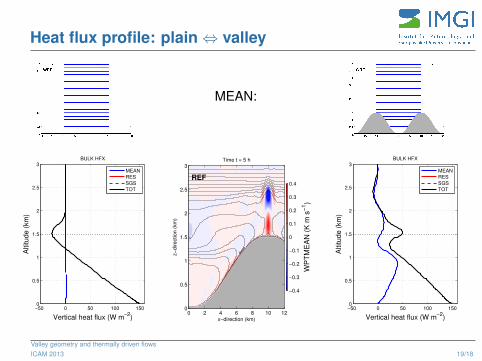
Heat flux profile: plain ⇔ valley
MEAN:
Vertical heat flux (W m−2
)
Altitu
de
(km
)
BULK HFX
−50 0 50 100 1500
0.5
1
1.5
2
2.5
3
MEAN
RES
SGS
TOT
x−direction (km)
z−
direction (
km
)
Time t = 5 h
303
REF
0 2 4 6 8 10 120
0.5
1
1.5
2
2.5
3
WP
TM
EA
N (
K m
s−
1)
−0.4
−0.3
−0.2
−0.1
0
0.1
0.2
0.3
0.4
Vertical heat flux (W m−2
)
Altitu
de
(km
)
BULK HFX
−50 0 50 100 1500
0.5
1
1.5
2
2.5
3
MEAN
RES
SGS
TOT
Valley geometry and thermally driven flowsICAM 2013 19/18
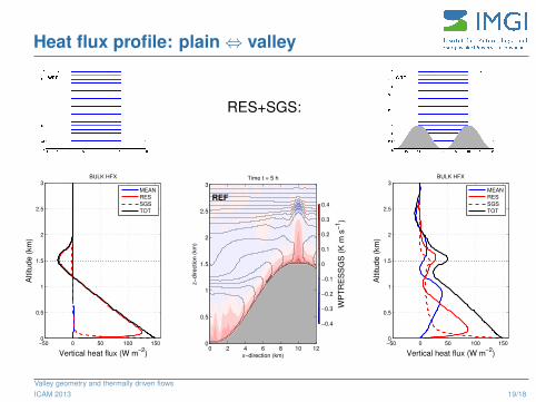
Heat flux profile: plain ⇔ valley
RES+SGS:
Vertical heat flux (W m−2
)
Altitu
de
(km
)
BULK HFX
−50 0 50 100 1500
0.5
1
1.5
2
2.5
3
MEAN
RES
SGS
TOT
x−direction (km)
z−
direction (
km
)
Time t = 5 h
303
REF
0 2 4 6 8 10 120
0.5
1
1.5
2
2.5
3
WP
TR
ES
SG
S (
K m
s−
1)
−0.4
−0.3
−0.2
−0.1
0
0.1
0.2
0.3
0.4
Vertical heat flux (W m−2
)
Altitu
de
(km
)
BULK HFX
−50 0 50 100 1500
0.5
1
1.5
2
2.5
3
MEAN
RES
SGS
TOT
Valley geometry and thermally driven flowsICAM 2013 19/18
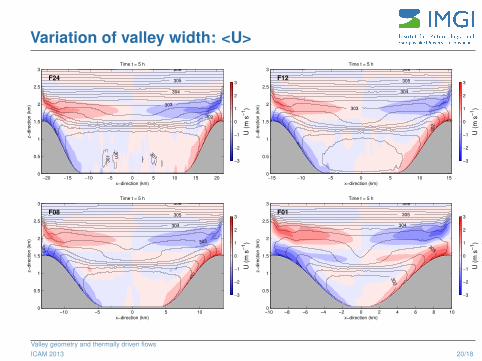
Variation of valley width: <U>
x−direction (km)
z−
direction (
km
)
Time t = 5 h
301
301
301
302
302
303
304
305
306
F24
−20 −15 −10 −5 0 5 10 15 200
0.5
1
1.5
2
2.5
3
U (
m s
−1)
−3
−2
−1
0
1
2
3
x−direction (km)
z−
direction (
km
)
Time t = 5 h
302
302
303
303 303
303
304
305
306
F08
−10 −5 0 5 100
0.5
1
1.5
2
2.5
3
U (
m s
−1)
−3
−2
−1
0
1
2
3
x−direction (km)
z−
direction (
km
)
Time t = 5 h
302
302
303
303303
304
305
306
F12
−15 −10 −5 0 5 10 150
0.5
1
1.5
2
2.5
3
U (
m s
−1)
−3
−2
−1
0
1
2
3
x−direction (km)
z−
direction (
km
)
Time t = 5 h
302
303
303
304
305
306
F01
−10 −8 −6 −4 −2 0 2 4 6 8 100
0.5
1
1.5
2
2.5
3
U (
m s
−1)
−3
−2
−1
0
1
2
3
Valley geometry and thermally driven flowsICAM 2013 20/18
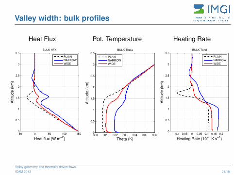
Valley width: bulk profiles
Heat Flux
Heat flux (W m−2
)
Altitude (
km
)
BULK HFX
−50 0 50 100 1500
0.5
1
1.5
2
2.5
3
3.5
PLAIN
NARROW
WIDE
Pot. Temperature
Theta (K)
Altitu
de
(km
)
BULK Theta
300 301 302 303 304 305 3060
0.5
1
1.5
2
2.5
3
3.5
PLAIN
NARROW
WIDE
Heating Rate
Heating Rate (10−3
K s−1
)
Altitude (
km
)
BULK Tend
−0.1 −0.05 0 0.05 0.1 0.15 0.20
0.5
1
1.5
2
2.5
3
3.5
PLAIN
NARROW
WIDE
Valley geometry and thermally driven flowsICAM 2013 21/18
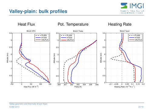
Valley-plain: bulk profiles
Heat Flux
Heat Flux (W m−2
)
Altitu
de
(km
)
BULK HFX
−50 0 50 100 1500
0.5
1
1.5
2
2.5
3
3.5
PLAIN
H1500
VALPLA
Pot. Temperature
Theta (K)
Altitude (
km
)
BULK Theta
300 301 302 303 304 305 3060
0.5
1
1.5
2
2.5
3
3.5
PLAIN
H1500
VALPLA
Heating Rate
Heating Rate (10−3
K s−1
)
Altitu
de
(km
)
BULK Tend
−0.1 −0.05 0 0.05 0.1 0.15 0.20
0.5
1
1.5
2
2.5
3
3.5
PLAIN
H1500
VALPLA
Valley geometry and thermally driven flowsICAM 2013 22/18
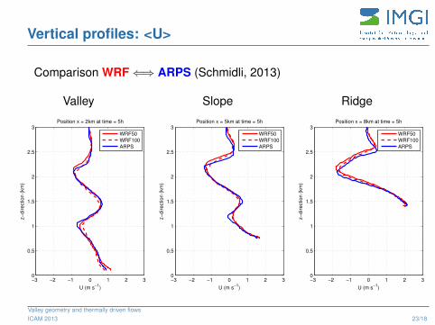
Vertical profiles: <U>
Comparison WRF ⇐⇒ ARPS (Schmidli, 2013)
Valley
U (m s−1
)
z−
dire
ctio
n (
km
)
Position x = 2km at time = 5h
−3 −2 −1 0 1 2 30
0.5
1
1.5
2
2.5
3
WRF50
WRF100
ARPS
Slope
U (m s−1
)
z−
dire
ctio
n (
km
)
Position x = 5km at time = 5h
−3 −2 −1 0 1 2 30
0.5
1
1.5
2
2.5
3
WRF50
WRF100
ARPS
Ridge
U (m s−1
)
z−
dire
ctio
n (
km
)
Position x = 8km at time = 5h
−3 −2 −1 0 1 2 30
0.5
1
1.5
2
2.5
3
WRF50
WRF100
ARPS
Valley geometry and thermally driven flowsICAM 2013 23/18
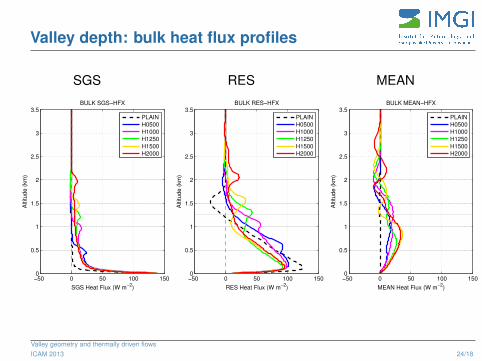
Valley depth: bulk heat flux profiles
SGS
SGS Heat Flux (W m−2
)
Altitu
de
(km
)
BULK SGS−HFX
−50 0 50 100 1500
0.5
1
1.5
2
2.5
3
3.5
PLAIN
H0500
H1000
H1250
H1500
H2000
RES
RES Heat Flux (W m−2
)
Altitu
de
(km
)
BULK RES−HFX
−50 0 50 100 1500
0.5
1
1.5
2
2.5
3
3.5
PLAIN
H0500
H1000
H1250
H1500
H2000
MEAN
MEAN Heat Flux (W m−2
)
Altitu
de
(km
)
BULK MEAN−HFX
−50 0 50 100 1500
0.5
1
1.5
2
2.5
3
3.5
PLAIN
H0500
H1000
H1250
H1500
H2000
Valley geometry and thermally driven flowsICAM 2013 24/18
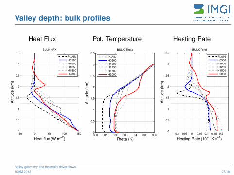
Valley depth: bulk profiles
Heat Flux
Heat flux (W m−2
)
Altitude (
km
)
BULK HFX
−50 0 50 100 1500
0.5
1
1.5
2
2.5
3
3.5
PLAIN
H0500
H1000
H1250
H1500
H2000
Pot. Temperature
Theta (K)
Altitu
de
(km
)
BULK Theta
300 301 302 303 304 305 3060
0.5
1
1.5
2
2.5
3
3.5
PLAIN
H0500
H1000
H1250
H1500
H2000
Heating Rate
Heating Rate (10−3
K s−1
)
Altitude (
km
)
BULK Tend
−0.1 −0.05 0 0.05 0.1 0.15 0.20
0.5
1
1.5
2
2.5
3
3.5
PLAIN
H0500
H1000
H1250
H1500
H2000
Valley geometry and thermally driven flowsICAM 2013 25/18
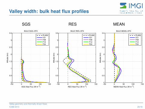
Valley width: bulk heat flux profiles
SGS
SGS Heat Flux (W m−2
)
Altitu
de
(km
)
BULK SGS−HFX
−50 0 50 100 1500
0.5
1
1.5
2
2.5
3
3.5
PLAIN
F01
F08
F12
F24
RES
RES Heat Flux (W m−2
)
Altitu
de
(km
)
BULK RES−HFX
−50 0 50 100 1500
0.5
1
1.5
2
2.5
3
3.5
PLAIN
F01
F08
F12
F24
MEAN
MEAN Heat Flux (W m−2
)
Altitu
de
(km
)
BULK MEAN−HFX
−50 0 50 100 1500
0.5
1
1.5
2
2.5
3
3.5
PLAIN
F01
F08
F12
F24
Valley geometry and thermally driven flowsICAM 2013 26/18
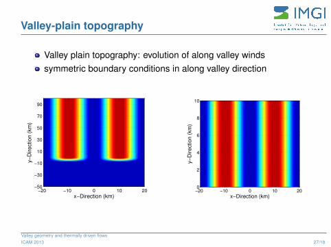
Valley-plain topography
Valley plain topography: evolution of along valley windssymmetric boundary conditions in along valley direction
x−Direction (km)
y−
Direction (
km
)
−20 −10 0 10 20−50
−30
−10
10
30
50
70
90
x−Direction (km)
y−
Dire
ctio
n (
km
)−20 −10 0 10 200
2
4
6
8
10
Valley geometry and thermally driven flowsICAM 2013 27/18
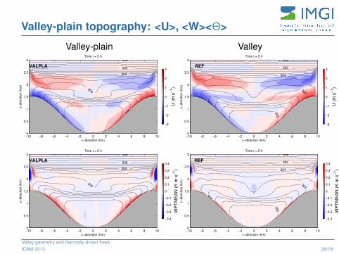
Valley-plain topography: <U>, <W><Θ>
Valley-plain
x−direction (km)
z−
direction (
km
)
Time t = 5 h
302
302
303
303
304
305
306
VALPLA
−10 −8 −6 −4 −2 0 2 4 6 8 100
0.5
1
1.5
2
2.5
3
U (
m s
−1)
−3
−2
−1
0
1
2
3
x−direction (km)
z−
direction (
km
)
Time t = 5 h
302
302
303
303
304
305
306
VALPLA
−10 −8 −6 −4 −2 0 2 4 6 8 100
0.5
1
1.5
2
2.5
3
WP
TM
EA
N (
K m
s−
1)
−0.4
−0.3
−0.2
−0.1
0
0.1
0.2
0.3
0.4
Valley
x−direction (km)
z−
direction (
km
)
Time t = 5 h
302
303
303
304
305
306
REF
−10 −8 −6 −4 −2 0 2 4 6 8 100
0.5
1
1.5
2
2.5
3
U (
m s
−1)
−3
−2
−1
0
1
2
3
x−direction (km)
z−
direction (
km
)
Time t = 5 h
302
303
303
304
305
306
REF
−10 −8 −6 −4 −2 0 2 4 6 8 100
0.5
1
1.5
2
2.5
3
WP
TM
EA
N (
K m
s−
1)
−0.4
−0.3
−0.2
−0.1
0
0.1
0.2
0.3
0.4
Valley geometry and thermally driven flowsICAM 2013 28/18
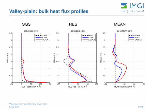
Valley-plain: bulk heat flux profiles
SGS
SGS Heat Flux (W m−2
)
Altitu
de
(km
)
BULK SGS−HFX
−50 0 50 100 1500
0.5
1
1.5
2
2.5
3
3.5
PLAIN
H1500
VALPLA
RES
RES Heat Flux (W m−2
)
Altitu
de
(km
)
BULK RES−HFX
−50 0 50 100 1500
0.5
1
1.5
2
2.5
3
3.5
PLAIN
H1500
VALPLA
MEAN
MEAN Heat Flux (W m−2
)
Altitu
de
(km
)
BULK MEAN−HFX
−50 0 50 100 1500
0.5
1
1.5
2
2.5
3
3.5
PLAIN
H1500
VALPLA
Valley geometry and thermally driven flowsICAM 2013 29/18
Recommended