The evolution of dewatering systems for CBM/CSG
applications – past, present and future: motivation for a
new ESPCP design
Lyon van der Merwe and Attie Jonker Don Brown
Franklin Electric SA (pty) ltd Franklin Electric Inc.
South Africa USA
13 Engwena Road, Sebenza, South Africa, 1610 400 East Spring Street, Bluffton, IN, 46714
[email protected] [email protected]
Abstract – The history of tight gas artificial lift systems
are discussed from a period and technology point of view.
Practical aspects of the particular dewatering process
(artificial lift process) are considered. The impact of new
pumping technologies and modern control gear and system
management principles are elaborated on. The advantages of
comprehensively designed system solutions with respect to the
particular application are discussed.
Index Terms – Artificial lift, coal bed methane, coal seam
gas, dewatering, systems.
I. INTRODUCTION
While coal bed methane or coal seam gas (CMB/CSG)
operations are associated with the oil and gas industry,
several aspects of such operations justify viewing the
dewatering process or hydrostatic pressure reduction or
artificial lift operation from a more conventional ground
dewatering perspective. The significant amount of
descriptive terms for the process is already a clue to the
overlap of the same functional requirement, albeit
approached from a different industry. At no time however,
should the requirements in the CBM/CSG production
industry with respect to safety, reliable operation be ignored.
In fact, additional effort should be considered to increase
safety, reliability, time between work overs and
serviceability.
A. Artificial lift
Artificial lift or the reduction of hydrostatic pressure is
required in cases where the natural gas pressure formed in
the coal seams cannot overcome the hydrostatic pressure. It
is also advantageous to reduce the hydrostatic pressure in
order to increase gas production.
1) Artificial lift process: The process of artificial lift
provides external energy to create additional drawdown on
the formation. This can be achieved with a rod pump, a
progressing cavity pump (surface driven – PCP or
submersible driven - ESPCP), an electrical submersible
pump (ESP) or gas compression.
2) Typical dewatering requirement: CBM/CSG
applications require (potentially) a widely varying range of
artificial lift or dewatering requirements – from several
hundreds of barrels of water per day to only a few barrels of
water per day. Irrespective of the rate of pumping, it should
always be under controlled conditions.
3) Multiple well environments: Another characteristic of
specifically CBM/CSG operations are the use of multiple
wells in (often) close proximity. Therefore, when
considering artificial lift requirements in such applications a
multiple well viewpoint should rather be considered, as
opposed to single well operation. Several advantages could
be obtained when operating from a more holistic point of
view.
II. HISTORY OF CBM/CSG DEWATERING
The CBM/CSG industry found its origin in the oil and gas
industry. This is especially relevant since, notwithstanding
the nature of the oil and gas industry with respect to safety
and reliability, CBM/CSG application are associated with
deep settings, high pressures, and high powers and is based
on trusted and reliable product and long term experience.
A. Early days
During the early days of CBM/CSG the artificial lift or
dewatering equipment used, mostly stemmed from the oil
and gas industry to which the CBM/CSG industry belongs.
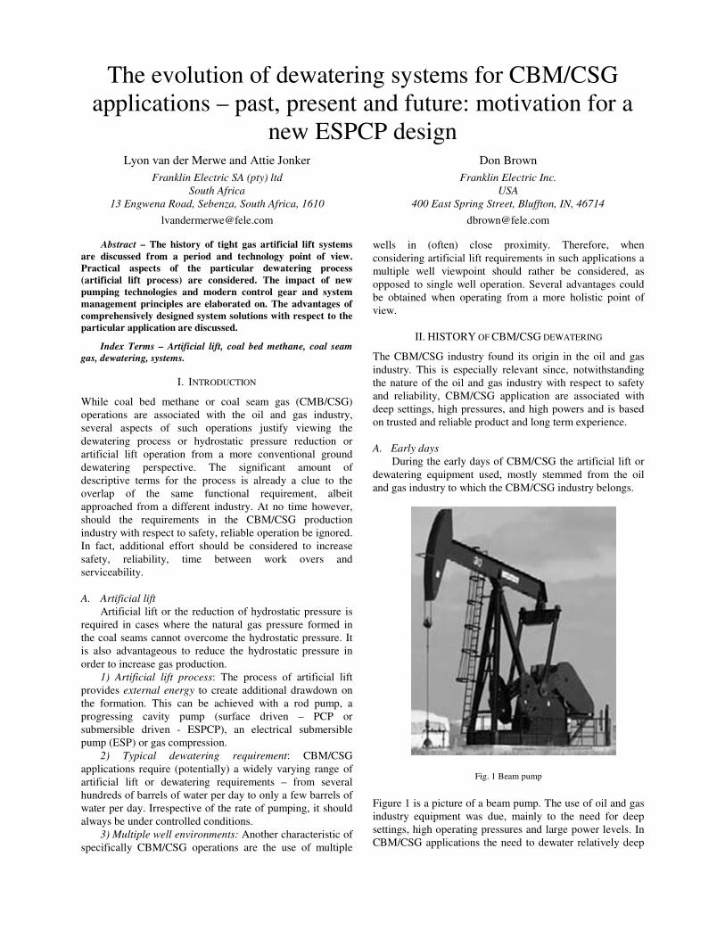
Fig. 1 Beam pump
Figure 1 is a picture of a beam pump. The use of oil and gas
industry equipment was due, mainly to the need for deep
settings, high operating pressures and large power levels. In
CBM/CSG applications the need to dewater relatively deep
coal seams (usually far below the useful groundwater level)
meant that the more conventional well or borehole
equipment could not easily meet the CBM/CSG dewatering
needs. Often the balance between operating power levels and
the need for high starting torque also influenced and biased
the use of oil and gas artificial lift equipment in the
CBM/CSG industry.
Fig. 2 Surface driven progressing cavity pump (typically 2-3 meters off the
ground).
However, these products were trusted and had long term
records of reliability and were technologies that was well
understood, meaning that expertise were available to operate
and service the equipment. In fact that is still true for today.
B. Later development
Eventually the products used in conventional water well
pumping applications found its way into the CBM/CSG
industry – including the necessary modifications with respect
to materials, robustness and adaption of pressure and flow
characteristics.
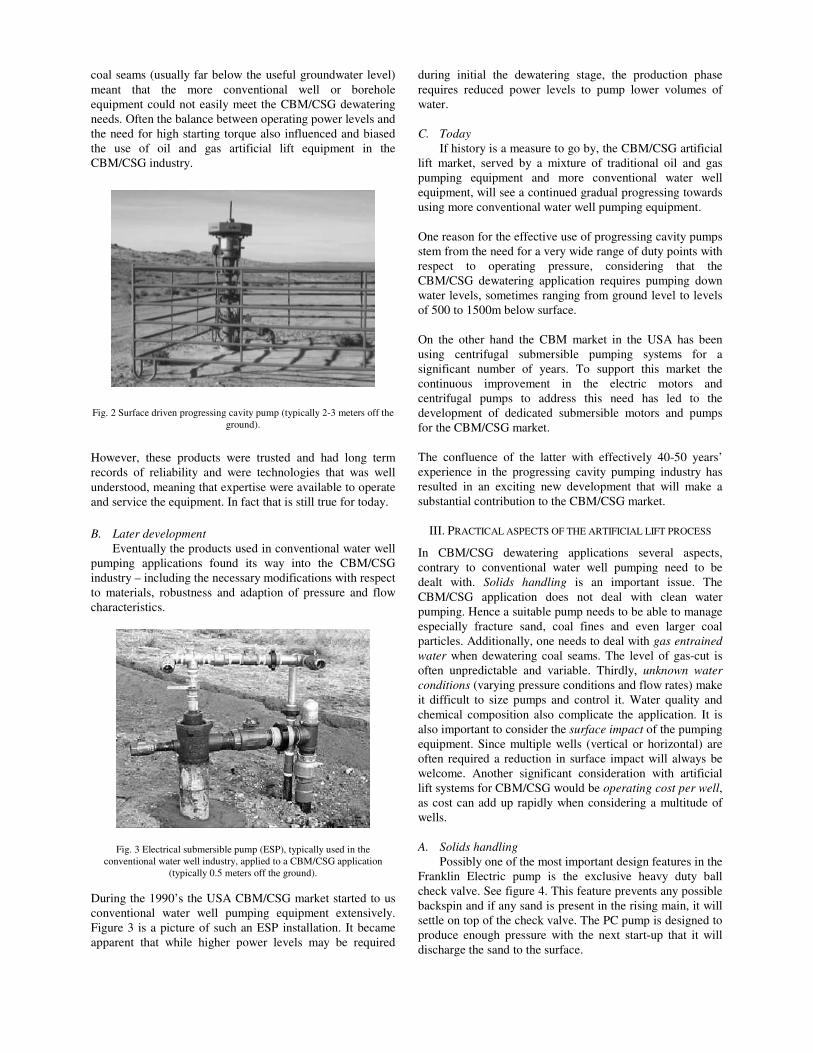
Fig. 3 Electrical submersible pump (ESP), typically used in the
conventional water well industry, applied to a CBM/CSG application
(typically 0.5 meters off the ground).
During the 1990’s the USA CBM/CSG market started to us
conventional water well pumping equipment extensively.
Figure 3 is a picture of such an ESP installation. It became
apparent that while higher power levels may be required
during initial the dewatering stage, the production phase
requires reduced power levels to pump lower volumes of
water.
C. Today
If history is a measure to go by, the CBM/CSG artificial
lift market, served by a mixture of traditional oil and gas
pumping equipment and more conventional water well
equipment, will see a continued gradual progressing towards
using more conventional water well pumping equipment.
One reason for the effective use of progressing cavity pumps
stem from the need for a very wide range of duty points with
respect to operating pressure, considering that the
CBM/CSG dewatering application requires pumping down
water levels, sometimes ranging from ground level to levels
of 500 to 1500m below surface.
On the other hand the CBM market in the USA has been
using centrifugal submersible pumping systems for a
significant number of years. To support this market the
continuous improvement in the electric motors and
centrifugal pumps to address this need has led to the
development of dedicated submersible motors and pumps
for the CBM/CSG market.
The confluence of the latter with effectively 40-50 years’
experience in the progressing cavity pumping industry has
resulted in an exciting new development that will make a
substantial contribution to the CBM/CSG market.
III. PRACTICAL ASPECTS OF THE ARTIFICIAL LIFT PROCESS
In CBM/CSG dewatering applications several aspects,
contrary to conventional water well pumping need to be
dealt with. Solids handling is an important issue. The
CBM/CSG application does not deal with clean water
pumping. Hence a suitable pump needs to be able to manage
especially fracture sand, coal fines and even larger coal
particles. Additionally, one needs to deal with gas entrained
water when dewatering coal seams. The level of gas-cut is
often unpredictable and variable. Thirdly, unknown water
conditions (varying pressure conditions and flow rates) make
it difficult to size pumps and control it. Water quality and
chemical composition also complicate the application. It is
also important to consider the surface impact of the pumping
equipment. Since multiple wells (vertical or horizontal) are
often required a reduction in surface impact will always be
welcome. Another significant consideration with artificial
lift systems for CBM/CSG would be operating cost per well,
as cost can add up rapidly when considering a multitude of
wells.
A. Solids handling
Possibly one of the most important design features in the
Franklin Electric pump is the exclusive heavy duty ball
check valve. See figure 4. This feature prevents any possible
backspin and if any sand is present in the rising main, it will
settle on top of the check valve. The PC pump is designed to
produce enough pressure with the next start-up that it will
discharge the sand to the surface.
A further consideration for any installation is to use the
smallest diameter pipe possible with the correct
specifications to ensure that the highest water velocity
possible is achieved, to move any frac sand and/or coal fines
through the discharge. Features such as these contribute
substantially to the success of the ESPCP design, as has been
proven in case studies. See later on. Pumps pulled for
routine inspection contained up to 10m of pipe above the
pump filled with frac sand and coal fines.
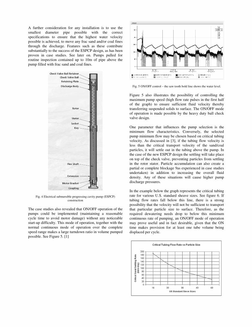
Fig. 4 Electrical submersible progressing cavity pump (ESPCP)
construction
The case studies also revealed that ON/OFF operation of the
pumps could be implemented (maintaining a reasonable
cycle time to avoid motor damage) without any noticeable
start-up difficulty. This mode of operation, together with the
normal continuous mode of operation over the complete
speed range makes a large turndown ratio in volume pumped
possible. See Figure 5. [1]
Fig. 5 ON/OFF control – the saw tooth bold line shows the water level.
Figure 5 also illustrates the possibility of controlling the
maximum pump speed (high flow rate pulses in the first half
of the graph) to ensure sufficient fluid velocity thereby
transferring suspended solids to surface. The ON/OFF mode
of operation is made possible by the heavy duty ball check
valve design.
One parameter that influences the pump selection is the
minimum flow characteristics. Conversely, the selected
pump minimum flow may be chosen based on critical tubing
velocity. As discussed in [3], if the tubing flow velocity is
less than the critical transport velocity of the sand/coal
particles, it will settle out in the tubing above the pump. In
the case of the new ESPCP design the settling will take place
on top of the check valve, preventing particles from settling
in the rotor stator. Particle accumulation can also create a
partial or complete blockage 9as experienced in case studies
undertaken) in addition to increasing the overall fluid
density. Any of these situations will cause higher pump
discharge pressures.
In the example below the graph represents the critical tubing
rate for various U.S. standard sheave sizes. See figure 6. If
tubing flow rates fall below this line, there is a strong
possibility that the velocity will not be sufficient to transport
that particular particle size to surface. Therefore, as the
required dewatering needs drop to below this minimum
continuous rate of pumping, an ON/OFF mode of operation
may prove useful and in fact desirable, given that the ON
time makes provision for at least one tube volume being
displaced per cycle.
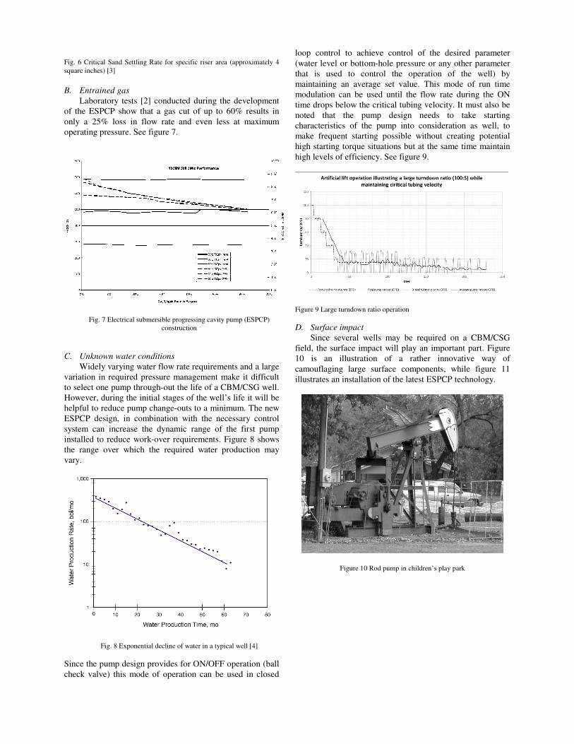
Fig. 6 Critical Sand Settling Rate for specific riser area (approximately 4
square inches) [3]
B. Entrained gas
Laboratory tests [2] conducted during the development
of the ESPCP show that a gas cut of up to 60% results in
only a 25% loss in flow rate and even less at maximum
operating pressure. See figure 7.
Fig. 7 Electrical submersible progressing cavity pump (ESPCP)
construction
C. Unknown water conditions
Widely varying water flow rate requirements and a large
variation in required pressure management make it difficult
to select one pump through-out the life of a CBM/CSG well.
However, during the initial stages of the well’s life it will be
helpful to reduce pump change-outs to a minimum. The new
ESPCP design, in combination with the necessary control
system can increase the dynamic range of the first pump
installed to reduce work-over requirements. Figure 8 shows
the range over which the required water production may
vary.
Fig. 8 Exponential decline of water in a typical well [4]
Since the pump design provides for ON/OFF operation (ball
check valve) this mode of operation can be used in closed
loop control to achieve control of the desired parameter
(water level or bottom-hole pressure or any other parameter
that is used to control the operation of the well) by
maintaining an average set value. This mode of run time
modulation can be used until the flow rate during the ON
time drops below the critical tubing velocity. It must also be
noted that the pump design needs to take starting
characteristics of the pump into consideration as well, to
make frequent starting possible without creating potential
high starting torque situations but at the same time maintain
high levels of efficiency. See figure 9.
Figure 9 Large turndown ratio operation
D. Surface impact
Since several wells may be required on a CBM/CSG
field, the surface impact will play an important part. Figure
10 is an illustration of a rather innovative way of
camouflaging large surface components, while figure 11
illustrates an installation of the latest ESPCP technology.
Figure 10 Rod pump in children’s play park
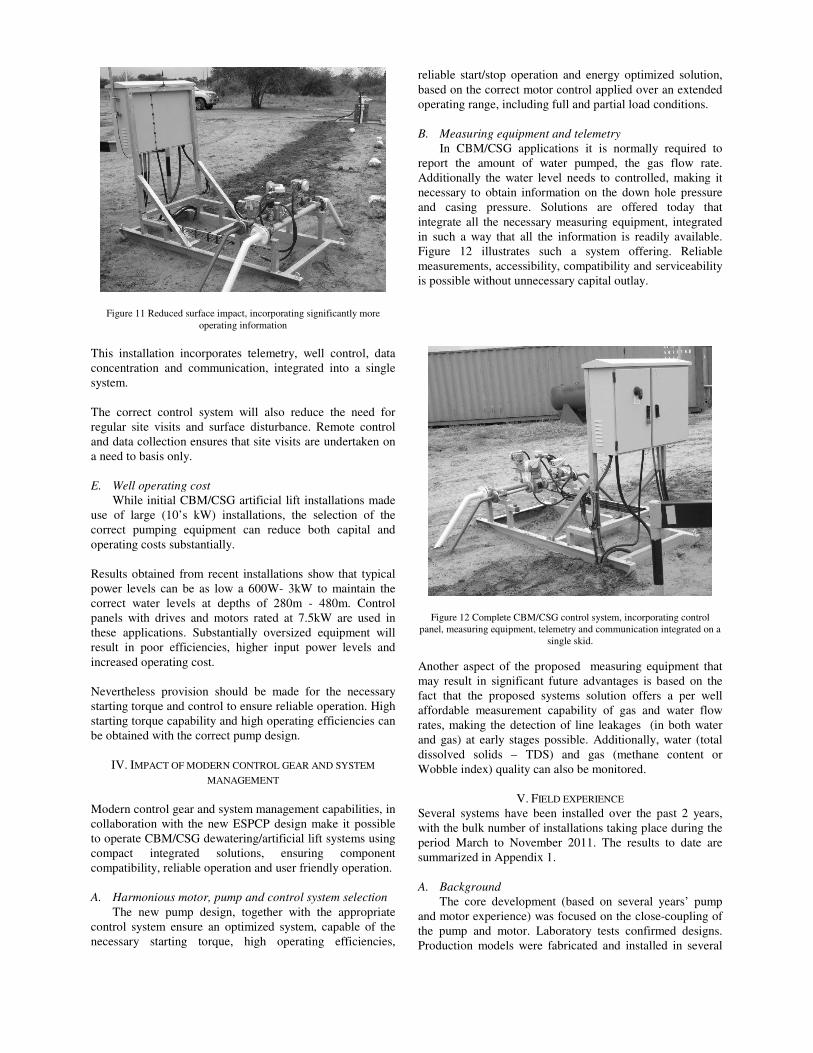
Figure 11 Reduced surface impact, incorporating significantly more
operating information
This installation incorporates telemetry, well control, data
concentration and communication, integrated into a single
system.
The correct control system will also reduce the need for
regular site visits and surface disturbance. Remote control
and data collection ensures that site visits are undertaken on
a need to basis only.
E. Well operating cost
While initial CBM/CSG artificial lift installations made
use of large (10’s kW) installations, the selection of the
correct pumping equipment can reduce both capital and
operating costs substantially.
Results obtained from recent installations show that typical
power levels can be as low a 600W- 3kW to maintain the
correct water levels at depths of 280m - 480m. Control
panels with drives and motors rated at 7.5kW are used in
these applications. Substantially oversized equipment will
result in poor efficiencies, higher input power levels and
increased operating cost.
Nevertheless provision should be made for the necessary
starting torque and control to ensure reliable operation. High
starting torque capability and high operating efficiencies can
be obtained with the correct pump design.
IV. IMPACT OF MODERN CONTROL GEAR AND SYSTEM
MANAGEMENT
Modern control gear and system management capabilities, in
collaboration with the new ESPCP design make it possible
to operate CBM/CSG dewatering/artificial lift systems using
compact integrated solutions, ensuring component
compatibility, reliable operation and user friendly operation.
A. Harmonious motor, pump and control system selection
The new pump design, together with the appropriate
control system ensure an optimized system, capable of the
necessary starting torque, high operating efficiencies,
reliable start/stop operation and energy optimized solution,
based on the correct motor control applied over an extended
operating range, including full and partial load conditions.
B. Measuring equipment and telemetry
In CBM/CSG applications it is normally required to
report the amount of water pumped, the gas flow rate.
Additionally the water level needs to controlled, making it
necessary to obtain information on the down hole pressure
and casing pressure. Solutions are offered today that
integrate all the necessary measuring equipment, integrated
in such a way that all the information is readily available.
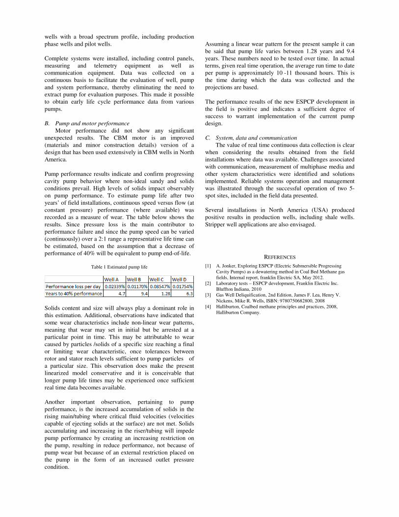
Figure 12 illustrates such a system offering. Reliable
measurements, accessibility, compatibility and serviceability
is possible without unnecessary capital outlay.
Figure 12 Complete CBM/CSG control system, incorporating control
panel, measuring equipment, telemetry and communication integrated on a
single skid.
Another aspect of the proposed measuring equipment that
may result in significant future advantages is based on the
fact that the proposed systems solution offers a per well
affordable measurement capability of gas and water flow
rates, making the detection of line leakages (in both water
and gas) at early stages possible. Additionally, water (total
dissolved solids – TDS) and gas (methane content or
Wobble index) quality can also be monitored.
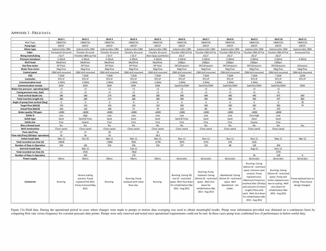
V. FIELD EXPERIENCE
Several systems have been installed over the past 2 years,
with the bulk number of installations taking place during the
period March to November 2011. The results to date are
summarized in Appendix 1.
A. Background
The core development (based on several years’ pump
and motor experience) was focused on the close-coupling of
the pump and motor. Laboratory tests confirmed designs.
Production models were fabricated and installed in several
wells with a broad spectrum profile, including production
phase wells and pilot wells.
Complete systems were installed, including control panels,
measuring and telemetry equipment as well as
communication equipment. Data was collected on a
continuous basis to facilitate the evaluation of well, pump
and system performance, thereby eliminating the need to
extract pump for evaluation purposes. This made it possible
to obtain early life cycle performance data from various
pumps.
B. Pump and motor performance
Motor performance did not show any significant
unexpected results. The CBM motor is an improved
(materials and minor construction details) version of a
design that has been used extensively in CBM wells in North
America.
Pump performance results indicate and confirm progressing
cavity pump behavior where non-ideal sandy and solids
conditions prevail. High levels of solids impact observably
on pump performance. To estimate pump life after two
years’ of field installations, continuous speed versus flow (at
constant pressure) performance (where available) was
recorded as a measure of wear. The table below shows the
results. Since pressure loss is the main contributor to
performance failure and since the pump speed can be varied
(continuously) over a 2:1 range a representative life time can
be estimated, based on the assumption that a decrease of
performance of 40% will be equivalent to pump end-of-life.
Table 1 Estimated pump life
Solids content and size will always play a dominant role in
this estimation. Additional, observations have indicated that
some wear characteristics include non-linear wear patterns,
meaning that wear may set in initial but be arrested at a
particular point in time. This may be attributable to wear
caused by particles /solids of a specific size reaching a final
or limiting wear characteristic, once tolerances between
rotor and stator reach levels sufficient to pump particles of
a particular size. This observation does make the present
linearized model conservative and it is conceivable that
longer pump life times may be experienced once sufficient
real time data becomes available.
Another important observation, pertaining to pump
performance, is the increased accumulation of solids in the
rising main/tubing where critical fluid velocities (velocities
capable of ejecting solids at the surface) are not met. Solids
accumulating and increasing in the riser/tubing will impede
pump performance by creating an increasing restriction on
the pump, resulting in reduce performance, not because of
pump wear but because of an external restriction placed on
the pump in the form of an increased outlet pressure
condition.
Assuming a linear wear pattern for the present sample it can
be said that pump life varies between 1.28 years and 9.4
years. These numbers need to be tested over time. In actual
terms, given real time operation, the average run time to date
per pump is approximately 10 -11 thousand hours. This is
the time during which the data was collected and the
projections are based.
The performance results of the new ESPCP development in
the field is positive and indicates a sufficient degree of
success to warrant implementation of the current pump
design.
C. System, data and communication
The value of real time continuous data collection is clear
when considering the results obtained from the field
installations where data was available. Challenges associated
with communication, measurement of multiphase media and
other system characteristics were identified and solutions
implemented. Reliable systems operation and management
was illustrated through the successful operation of two 5-
spot sites, included in the field data presented.
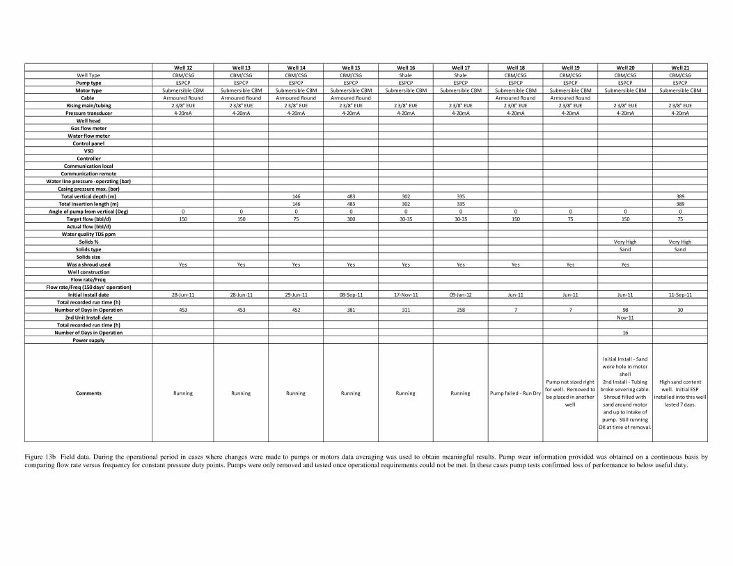
Several installations in North America (USA) produced
positive results in production wells, including shale wells.
Stripper well applications are also envisaged.
REFERENCES
[1] A. Jonker, Exploring ESPCP (Electric Submersible Progressing
Cavity Pumps) as a dewatering method in Coal Bed Methane gas
fields, Internal report, franklin Electric SA, May 2012.
[2] Laboratory tests – ESPCP development, Franklin Electric Inc.
Bluffton Indiana, 2010
[3] Gas Well Deliquification, 2nd Edition, James F. Lea, Henry V.
Nickens, Mike R. Wells, ISBN: 9780750682800, 2008
[4] Halliburton, Coalbed methane principles and practices, 2008,
Halliburton Company.
APPENDIX 1 - FIELD DATA
Well 1 Well 2 Well 3 Well 4 Well 5 Well 6 Well 7 Well 8 Well 9 Well 10 Well 11
Well Type CBM/CSG CBM/CSG CBM/CSG CBM/CSG CBM/CSG CBM/CSG CBM/CSG CBM/CSG CBM/CSG CBM/CSG CBM/CSG
Pump type ESPCP ESPCP ESPCP ESPCP ESPCP ESPCP ESPCP ESPCP ESPCP ESPCP ESPCP
Motor type Submersible CBM Submersible CBM Submersible CBM Submersible CBM Submersible CBM Submersible CBM Submersible CBM Submersible CBM Submersible CBM Submersible CBM Submersible CBM
Cable Permatrail 10 round Flexible 10 round Flexible 10 round Flexible 10 round Flexible 10 round Flexible CBM 10 Flat Flexible CBM 10 Flat Flexible CBM 10 Flat Flexible CBM 10 Flat Flexible CBM 10 Flat Armoured Flat
Rising main/tubing J 55 2" Flexible CBM Lay Flat J 55 2" J 55 2" Bore Quip (synthetic) J55 2" J55 2" J55 2" J55 2" J55 2"
Pressure transducer 4-20mA 4-20mA 4-20mA 4-20mA 4-20mA 4-20mA 4-20mA 4-20mA 4-20mA 4-20mA 4-20mA
Well head Modified Modified Modified Modified Modified 1500psi 1500psi 1500psi 1500psi 1500psi
Gas flow meter DP Pitot DP Pitot DP Pitot DP Pitot DP Pitot DP/Ultrasonic DP/Ultrasonic DP/Ultrasonic DP/Ultrasonic DP/Ultrasonic Ultrasonic
Water flow meter Mag flow Mag flow Mag flow Mag flow Mag flow Mag flow Mag flow Mag flow Mag flow Mag flow Mag flow
Control panel CBM skid mounted CBM skid mounted CBM skid mounted CBM skid mounted CBM skid mounted CBM skid mounted CBM skid mounted CBM skid mounted CBM skid mounted CBM skid mounted CBM skid mounted
VSD 7.5kW 7.5kW 7.5kW 7.5kW 7.5kW 7.5kW 7.5kW 7.5kW 7.5kW 7.5kW 11kW
Controller RTU IP RTU IP RTU IP RTU IP RTU IP RTU IP RTU IP RTU IP RTU IP RTU IP RTU IP
Communication local 2.4GHz 2.4GHz 2.4GHz 2.4GHz 2.4GHz 2.4GHz 2.4GHz 2.4GHz 2.4GHz 2.4GHz
Communication remote GSM GSM GSM GSM GSM Satellite/GSM Satellite/GSM Satellite/GSM Satellite/GSM Satellite/GSM GSM
Water line pressure -operating (bar) <3 <3 <3 <3 <3 <3 <3 <3 <3 <3
Casing pressure max. (bar) <5 <5 <5 <5 <5 <5 <5 <5 <5 <5
Total vertical depth (m) 286 280 274 286 280 490 484 480 490 475 690
Total insertion length (m) 286 280 274 286 280 490 484 480 490 475 800
Angle of pump from vertical (Deg) 0 0 0 0 0 0 0 0 0 0 78
Target flow (bbl/d) 150 150 150 150 150 300 300 300 300 300 74
Actual flow (bbl/d) 160 120 100 75 70 110 80 40 70 270
Water quality TDS ppm <4000 <6000 <4000 <4000 <4000 <3000 <3000 <3000 <3000 <6000
Solids % Low High Low Low Low Low Low Low Very high Low
Solids type Sand Sand & Fines Sand Sand Sand Sand & Fines Sand Sand Sand Sand
Solids size Fine Coarse Fine Fine Fine Fine Fine Fine Coarse Fine
Was a shroud used No No No No No No No No No No Yes
Well construction Close cased Close cased Close cased Close cased Close cased Close cased Close cased Close cased Close cased Close cased
Flow rate/Freq 57 57 39 - 19 - - - - -
Flow rate/Freq (150 days' operation) 55 56 34 - 18.5 - - - - -
Initial install date Mar-11 Oct-10 Mar-11 Mar-11 Mar-11 Nov-11 Nov-11 Nov-11 Nov-11 May-11 Mar-12
Total recorded run time (h) 10658 11894 7810 11795 3670 3710 676 3102
Number of Days in Operation 534 181 535 356 535 157 155 88 158 204
2nd Unit Install date Mar-11 Feb-12 Aug-12 Nov-11
Total recorded run time (h) 9725 -7810 3770
Number of Days in Operation 405 179 36 158 0
Power supply Mains Mains Mains Mains Mains Generator Generator Generator Generator Generator Generator
Comments Running
Severe scaling
present. Pump
replaced Feb 2012.
Pump removed May
2012.
Running.
Running. Pump
replaced with lower
flow rate.
Running.
Running. Casing 101
mm ID - restricted
space. Well shut down
for rehabilitation Mar
2012 - Aug 2012.
Running. Pump
replaced. Casing
101mm ID - restricted
space. Well shut
down for
rehabilitation Mar
2012 - Aug 2012
Abandoned. Casing
101mm ID - restricted
space. Well
abandoned - not
viable.
Running. Casing
101mm ID - restricted
space. Extreme sand
content. Pump
replaced once.
Maximum frequency
reached after 154 days
and coloumn (3 meter
length) filled with
sand. Well shut down
for rehabilitation Mar
2012 - Aug 2012
Running. Casing
101mm ID - restricted
space. Pump and
motor replaced once
due to scaling. Well
shut down for
rehabilitation Mar
2012 - Aug 2012
Pump replaced due to
silting. Flow sleeve
design changed.
Figure 13a Field data. During the operational period in cases where changes were made to pumps or motors data averaging was used to obtain meaningful results. Pump wear information provided was obtained on a continuous basis by
comparing flow rate versus frequency for constant pressure duty points. Pumps were only removed and tested once operational requirements could not be met. In these cases pump tests confirmed loss of performance to below useful duty.
Well 12 Well 13 Well 14 Well 15 Well 16 Well 17 Well 18 Well 19 Well 20 Well 21
Well Type CBM/CSG CBM/CSG CBM/CSG CBM/CSG Shale Shale CBM/CSG CBM/CSG CBM/CSG CBM/CSG
Pump type ESPCP ESPCP ESPCP ESPCP ESPCP ESPCP ESPCP ESPCP ESPCP ESPCP
Motor type Submersible CBM Submersible CBM Submersible CBM Submersible CBM Submersible CBM Submersible CBM Submersible CBM Submersible CBM Submersible CBM Submersible CBM
Cable Armoured Round Armoured Round Armoured Round Armoured Round Armoured Round Armoured Round
Rising main/tubing 2 3/8" EUE 2 3/8" EUE 2 3/8" EUE 2 3/8" EUE 2 3/8" EUE 2 3/8" EUE 2 3/8" EUE 2 3/8" EUE 2 3/8" EUE 2 3/8" EUE
Pressure transducer 4-20mA 4-20mA 4-20mA 4-20mA 4-20mA 4-20mA 4-20mA 4-20mA 4-20mA 4-20mA
Well head
Gas flow meter
Water flow meter
Control panel
VSD
Controller
Communication local
Communication remote
Water line pressure -operating (bar)
Casing pressure max. (bar)
Total vertical depth (m) 146 483 302 335 389
Total insertion length (m) 146 483 302 335 389
Angle of pump from vertical (Deg) 0 0 0 0 0 0 0 0 0 0
Target flow (bbl/d) 150 150 75 300 30-35 30-35 150 75 150 75
Actual flow (bbl/d)
Water quality TDS ppm
Solids % Very High Very High
Solids type Sand Sand
Solids size
Was a shroud used Yes Yes Yes Yes Yes Yes Yes Yes Yes
Well construction
Flow rate/Freq
Flow rate/Freq (150 days' operation)
Initial install date 28-Jun-11 28-Jun-11 29-Jun-11 08-Sep-11 17-Nov-11 09-Jan-12 Jun-11 Jun-11 Jun-11 11-Sep-11
Total recorded run time (h)
Number of Days in Operation 453 453 452 381 311 258 7 7 98 30
2nd Unit Install date Nov-11
Total recorded run time (h)
Number of Days in Operation 16
Power supply
Comments Running Running Running Running Running Running Pump failed - Run Dry
Pump not sized right
for well. Removed to
be placed in another
well
Initial Install - Sand
wore hole in motor
shell
2nd Install - Tubing
broke severing cable.
Shroud filled with
sand around motor
and up to intake of
pump. Still running
OK at time of removal.
High sand content
well. Initial ESP
installed into this well
lasted 7 days.
Figure 13b Field data. During the operational period in cases where changes were made to pumps or motors data averaging was used to obtain meaningful results. Pump wear information provided was obtained on a continuous basis by
comparing flow rate versus frequency for constant pressure duty points. Pumps were only removed and tested once operational requirements could not be met. In these cases pump tests confirmed loss of performance to below useful duty.
Recommended