Texas InstrumentsRegistration
andIdentification
System
Digital Signature23 mm Glass Transponder
RI-TRP-BRHP
Reference Manual
11-09-21-035 14 May 1997

Digital Signature 23 mm Glass Transponder 14 May 1997
DSTG-2
Edition Notice: First Edition - May 1997
This is the first edition of this manual, it describes the following transponder:
RI-TRP- BRHP
This Reference Manual is for customers who wish to use the TIRIS Digital Signature 23 mm GlassTransponder in Radio Frequency Identification (RFID) installations. The manual includes technicalinformation concerning the function, technical specifications, application and environmental related data.
Texas Instruments reserves the right to change its products or services at any time withoutnotice. TI provides customer assistance in various technical areas, but does not have fullaccess to data concerning the uses and applications of customer's products. Therefore TIassumes no responsibility for customer product design or for infringement of patents and/or therights of third parties, which may result from assistance provided by TI.
The TIRIS logo and the word TIRIS are registered trademarks of Texas Instruments Incorporated.
Copyright 1997 Texas Instruments Incorporated.
All rights reserved.

14 May 1997 Digital Signature 23 mm Glass Transponder
DSTG-3
Contents
1. Introduction.................................................................................................................. 52. Transponder Packaging................................................................................................. 63. References..................................................................................................................... 74. Product Codes.............................................................................................................. 75. System Description and Method of Operation................................................................ 8
5.1 General................................................................................................................... 85.2 Interrogator............................................................................................................. 85.3 Method of Operation............................................................................................... 8
5.3.1 Initialization.................................................................................................... 95.3.2 Encryption Mode ...........................................................................................105.3.3 Password Protection ......................................................................................11
5.4 Transponder............................................................................................................115.4.1 Memory.........................................................................................................11
5.4.1.1 Password EEPROM (Page 1) .........................................................115.4.1.2 Identification EEPROM (Page 2) .....................................................125.4.1.3 Serial Number (Page 3) ...................................................................135.4.1.4 Encryption Key EEPROM (Page 4) .................................................13
5.4.2 Cyclic Redundancy Check Generator .............................................................135.4.3 Encryption Algorithm .....................................................................................15
6. Function........................................................................................................................166.1 Charge....................................................................................................................166.2 Write .....................................................................................................................16
6.2.1 Write Data Formats........................................................................................186.3 Read/Response Data...............................................................................................18
6.3.1. Read Data Formats .......................................................................................197. Characteristics of the TIRIS FM System........................................................................21
7.1 Basic System Data ..................................................................................................217.2 Reader and System Design Impact...........................................................................217.3 System Performance and Functional Reliability Impact..............................................217.4 Other Quality Factors of the TIRIS FM System.......................................................22
8. EMI/EMC Performance................................................................................................228.1 General...................................................................................................................228.2 The Automotive Environment and Factors................................................................228.3 TIRIS FM Transponder and System Performance....................................................23
9. Measurement Set-Ups ..................................................................................................259.1 Measurement Set-Up: Resonance freq., bandwidth, qual. factor of trp......................259.2 Measurement Set-Up: Powering Field Strength........................................................269.3 Measurement Set-Up: Transponder Signal Strength..................................................28
10. Specifications..............................................................................................................2910.1 Absolute Maximum Ratings ...................................................................................2910.2 Recommended Operating Conditions.....................................................................2910.3 Characteristics.......................................................................................................3010.4 Environmental Data and Reliability.........................................................................3110.5 Memory................................................................................................................3110.6 Package ................................................................................................................31

Digital Signature 23 mm Glass Transponder 14 May 1997
DSTG-4
Appendix A: Conversion Formula.......................................................................................32

14 May 1997 Digital Signature 23 mm Glass Transponder
DSTG-5
Figures
Figure 1: System Configuration Showing the Reader, Antenna and Transponder .................. 5Figure 2: Block Diagram of the TIRIS 23 mm Glass DST.................................................... 6Figure 3: Dimensions of the TIRIS 23 mm Glass DST (in mm) ............................................ 7Figure 4: RF Module - Block Schematic.............................................................................10Figure 5: Memory Organization..........................................................................................12Figure 6: Block Schematic of CRC Generator.....................................................................14Figure 7: Subroutine ‘Generate Block Check Character’.....................................................15Figure 8: Timing of Write function.......................................................................................16Figure 9: Voltage at the Transponder and Exciter (Reader) Coils during Typical Function..................................................................................................17Figure 10: Write Data Format of Encryption Mode.............................................................18Figure 11: FM Principle Used for the Read Function of TIRIS Transponders.......................19Figure 12: Read Data Format during Program and Lock Function.......................................20Figure 13: Read Data Format during Encryption Mode .......................................................20Figure 14: EMI Performance Test of the TIRIS System.......................................................23Figure 15: EMI performance at commonly used radio communication frequencies in automotive environment ...............................................................24Figure 16: Reading range under broad band noise (white noise) conditions...........................24Figure 17: Measurement set-up for the determination of transponder resonance frequency, bandwidth and quality factor.............................................25Figure 18: Determination of the resonance frequency and -3dB bandwidth by monitoring the pick-up coil voltage.....................................................................26Figure 19: Test set-up for powering field strength determination...........................................26Figure 20: Received signal at the pick up coil, if power field strength is sufficient...................27Figure 21: Determination of the transponder signal strength (data transmission signal strength) with Helmholtz aperture.......................................................................28Figure 22: Monitored signal voltage at the spectrum analyzer (time domain mode) ...............28

Digital Signature 23 mm Glass Transponder 14 May 1997
DSTG-6
1. Introduction
The TIRIS Digital Signature Glass Transponder can be used for a variety of applications, such asautomotive security systems and other electronic locks. It is one product in the TIRIS low frequency RFIDproduct line.
Electromagnetic signals are used to:• power the passive (batteryless) device• exchange data between the reader unit and the device, or• program the device with new data.
The basic principle is described in Figure 1. The control unit sends any random number of predeterminedlength to the transponder, which is then scrambled in a unique way such that the control unit canauthenticate the response as being only from a valid transponder. The transponder scrambles the randomnumber in a unique way, based upon an encryption key which is known only by the control unit and thevalid transponder.
The 23 mm Glass Transponder comprises a ferrite core antenna, two capacitors and the integrated circuit(Figure 2). The antenna inductance and a capacitor form a high quality resonant circuit. The componentsare enclosed in a plastic housing.
The transponder has an 88 bit non-volatile memory for storage of an 8 bit password, an 8 bitidentification, a 24 bit serial number, an 8 bit manufacturer code and the 40 bit encryption key.
The complete system comprises an interrogator (RF module and control unit), an antenna (usually mountedaround the car keylock cylinder), and the transponder (in the key) as shown in figure 1.
RF Module
RI45538
TRANSPONDERTIRIS
CONTROLUNIT
ANTENNA
TIRIS INTERROGATOR
CHARGE
WRITE (PWM)
READ (FSK)
Figure 1: System Configuration Showing the Reader, Antenna and Transponder

14 May 1997 Digital Signature 23 mm Glass Transponder
DSTG-7
CHARGECAPACITOR
ANTENNA
TRANSPONDER IC
Figure 2: Block Diagram of the TIRIS 23 mm Glass DST
2. Transponder Packaging
The dimensions of the transponder are given in Figure 3.
The 23 mm shape offers several advantages:
1. The transponder is hermetically sealed.
2. The transponder is robustly constructed to withstand vibration (IEC68-2-6) and shock(IEC68-2-6).
3. For Applications where read range is not the most critical point the transponder can be mounted orused in such a way that the orientation is not controlled.
Figure 3: Dimensions of the TIRIS 23 mm Glass DST (in mm)

Digital Signature 23 mm Glass Transponder 14 May 1997
DSTG-8
3. References
[1] TIRIS RF Module IC Reference Manual Rev. 1.4, 05/31/94[2] Application Note ‘RF Module with IC RI45538’, Rev. 2.0, 12/12/94[3] Digital Signature Transponder Algorithm and Software Requirements (NDA Required)
Document number 24-09-05-012[4] Digital Signature Transponder Sequence Control Specification (NDA Required)
Document number 24-06-05-005
4. Product Codes
There are currently three products in the Digital Signature Transponder range, these are:
DST Wedge Transponder: RI-TRP-B9WKDST Block Transponder: RI-TRP-A9WKDST Glass Transponder: RI-TRP-BRHP

14 May 1997 Digital Signature 23 mm Glass Transponder
DSTG-9
5. System Description and Method of Operation
5.1 General
The method of operation requires the interrogator to send a charge-up signal together with a 40-bitinterrogation signal (challenge). The transponder then encrypts this 40-bit challenge and returns to theinterrogator a unique 24-bit response (signature) together with the transponder’s individual 24-bit serialnumber. The 24-bit response is a function of both the 40-bit challenge and the 40-bit encryption key thatwas written into the transponder by the interrogator during the initialization phase. This encryption key isheld in the memory of the reader and the transponder.
Programming can be made even more secure by the use of the password feature. If the password featureis enabled, the interrogator must first send the correct password to the transponder (together with thecharge-up) before the transponder can be programmed. However, use of the password for read orencryption functions is optional, even if the password feature is enabled.
5.2 Interrogator
The Interrogator consists of an RF module and a control unit. The RF module [2], built using a TIRIS RFModule IC RI45538 [1] is partitioned in the transmit and receive paths, both of which are connected to thesame antenna circuit (see figure 4).
The transmitter is used for contactless supply of the transponder (charge phase), for transmission of data tothe transponder (write phase) using pulse width modulation (PWM) and to program and lock thetransponder EEPROM (program phase). It is controlled by the active low transmit control input (TXCT-).
The receiver demodulates the transponder response signal (read phase), which is modulated usingFrequency Shift Keying (FSK). It provides a receive data output (RXDT) and a receive clock output(RXCK).
5.3 Method of Operation
Before the transponder can perform a proper encryption of a challenge its EEPROM must be initialized(programmed) by the interrogator (reader). This means that the interrogator has to write into thetransponder:
• the 8-bit password (if required),• the 8-bit identification (optional), and• the 40-bit encryption key.
During normal use (encryption mode), a 40-bit random number (challenge) is sent to the transponder. Thisrandom number is encrypted by the transponder using the encryption key. The resulting 24-bit response(signature) is returned to the interrogator together with the 24-bit serial number for verification andauthentication.

Digital Signature 23 mm Glass Transponder 14 May 1997
DSTG-10
The Password in the EEPROM can be programmed and locked by the interrogator. If enabled, theprogram and lock functions must be used in a selective addressing mode (password protected mode). Theother function of read and encryption allow for optional use of the password if it has been enabled.
Because the transponder is normally used together with RI-RFM-006A connected to a low Q keylockantenna, the write speed is increased, compared to standard TIRIS transponders.
5.3.1 Initialization
When the transponder is delivered, parts of the EEPROM are unlocked and must be programmed to thedesired password, identification number and encryption key. The write data formats are similar to the dataformats used with the standard TIRIS read/write transponders. Data transfer to the transponder isprotected by a Cyclic Redundancy Check (CRC), refer to section 5.4.2. For this purpose a 16-bit CRC-generator is used to generate the Block Check Character (BCC), which is sent along with the data whenprogramming and locking the transponder. It utilizes the CCITT algorithm but uses a start value which isdifferent than that used by other TIRIS transponders.
During the subsequent read phase (which is also protected by cyclic redundancy check), the newlyprogrammed password and/or identification number is returned to the interrogator, but not the encryptionkey. This means that once the encryption key has been programmed, the only method to check if theencryption key has been programmed correctly is by using the encryption mode with a test pattern. Asuccessful programming (initialization) is indicated by a status byte (called the read address) that is returnedas part of the read data format, refer to section 6.3.1.
Once the encryption key has been successfully programmed, it can be “locked”. The various modes ofLocking, Programming, and Encryption are controlled via a command (called the write address) that is sentto the transponder immediately after the charge phase, refer to section 6.2.1.
When the write data format for the encryption lock function, the identification lock function and/or thepassword lock function is sent to the transponder, the corresponding lock bit is set. Successful locking isindicated by the status field of the read address, which is sent by the transponder in response to a lockmode command. Locking prevents the EEPROM from being reprogrammed in future. Once set,the lock bit cannot be reset. Any attempt to reprogram the EEPROM is denied if the lock bit is set.

14 May 1997 Digital Signature 23 mm Glass Transponder
DSTG-11
TXCT-
VSP
RXCK
RXDT
ANT1
ANT2
RF MODULE
TRANSMITTER
ANTENNACIRCUIT
RECEIVER
AN
TEN
NA
POW
ER S
UPP
LY A
ND
CO
NTR
OL
MO
DU
LE
SEQSYS2.DRW
GND
Figure 4: RF Module - Block Schematic
5.3.2 Encryption Mode
In the encryption mode the interrogator sends (writes) the encryption command in the write addressfollowed by a 40-bit random number (challenge) to the transponder. The challenge is shifted into theencryption logic, which is also initialized with the 40-bit encryption key stored in EEPROM. When thechallenge has been completely received, a block cipher algorithm is executed using both the challenge andthe encryption key. If fewer or more bits are received, a discharge is executed in the subsequent readphase (no response).
Once it detects the end of the encryption phase, the transponder responds by sending the 24 bit serialnumber stored in the EEPROM and a 24 bit response (signature) that was generated by the block cipheralgorithm.

Digital Signature 23 mm Glass Transponder 14 May 1997
DSTG-12
5.3.3 Password Protection
If a password has been programmed into the transponder’s EEPROM, the program and lock modes(functions) must be selectively addressed (using the password). These functions are only executed if thepassword sent to the transponder matches the password stored in the transponder. All encryption andread modes (functions) will work with or without selective addressing (using the password). The passwordcan be programmed and locked by the user.
5.4 Transponder
5.4.1 Memory
The memory in the transponder comprises four pages as shown in figure 5. Each page has a separate lockbit, which is either programmable by the user or set during manufacture. The data is accessed via serialshift registers during write and read functions.
5.4.1.1 Password EEPROM (Page 1)
The password EEPROM contains 8 password bits and a password lock bit. The password is used forselective programming, selective locking, selective reading and selective encryption. The passwordEEPROM is programmable by the user (as long as the password lock bit is not set) via the program page1 function. The password lock bit can be set by the user, using the lock page 1 command (write address).Once set, the password lock bit cannot be reset.
To activate the password feature, the user must write a password other than ‘11111111’ into page 1. Ifthe password in the EEPROM is not ‘11111111’, it will be compared with the password received fromthe interrogator (write phase). If the password is ‘11111111’ (default) no comparison is performed.
When page 1,2 or 3 is addressed the password (page 1) is returned in a consecutive read phase togetherwith the identification (page2), manufacturer code and serial number (page 3). The status of page 1 lockbit is returned only when page 1 is addressed.

14 May 1997 Digital Signature 23 mm Glass Transponder
DSTG-13
1LSBMSB
8
DATA LOCK BIT
LOC
K
1LSBMSB
LOC
K
MSB LSB
PASSWORD LOCK BITPASSWORD EEPROM
PASS-WORD
IDENTIFICATION EEPROM
PAGE 1
8
IDENTI-FICATION
PAGE 2
1MSB
LOC
K
LSB
ENCRYPTION LOCK BIT
ENCRYPTION KEY
40
PAGE 4
SERIAL NUMBER
824
PAGE 3
LSB MSB
ENCRYPTION KEY EEPROM
SEQEEP1B.DRW
DATA MEMORY
MANUF. CODE
SERIAL NUMBER
Figure 5: Memory Organization
5.4.1.2 Identification EEPROM (Page 2)
The identification EEPROM contains 8 identification bits and an identification lock bit. The identification istypically used for numbering of the keys within an application (for example: the key number per car). Theidentification EEPROM is programmable by the user (as long as the identification lock bit is not set) withprogram page 2 function. The identification lock bit can be set by the user, using the lock page 2 command(write address). Once set the identification lock bit cannot be reset.
The contents of the identification EEPROM (read data) and the status (locked or unlocked) are returnedduring the read phase (read address), together with the password (page 1), the manufacturer code and theserial number (page 3) if page 1, 2 or 3 are addressed. The status of the lock bit is returned when page 2is addressed.

Digital Signature 23 mm Glass Transponder 14 May 1997
DSTG-14
5.4.1.3 Serial Number (Page 3)
The serial number memory portion contains an 8 bit manufacturer code and a 24-bit serial number. Themanufacturer code is used for distinguishing transponders sold to a specific manufacturer, so that thetransponder can only be used for applications for that manufacturer. The serial number is used fornumbering the transponder within an application.
The manufacturer code is programmed by TI, together with the serial number. The manufacturer code andserial number cannot be changed.
The contents of the manufacturer code together with the serial number is returned when page 1, 2 or 3 areaddressed, the status (locked) is returned when page 3 is addressed.
5.4.1.4 Encryption Key EEPROM (Page 4)
The encryption key EEPROM contains 40 encryption key bits and an encryption lock bit. The encryptionkey is used in the encryption logic to scramble the received random number (challenge) in order to generatethe encrypted response (signature).
The encryption EEPROM must be programmed by the user during the initialization phase (program page4). After it has been programmed, the encryption lock bit can then be set. The encryption lock bit can beset by the user using the lock page 4 command (write address). Once set the encryption lock bit cannot bereset.
The content of the encryption EEPROM is never returned during read phase. To find out if the encryptionkey is correct or not, a challenge must be sent to the transponder and the response (signature) checked.The status of the encryption lock bit (locked or unlocked) is returned during the read phase (read address),if the general read page 4 (encryption mode), selective read page 4 (selective encryption mode), theprogram page 4 or the lock page 4 function is initiated.
5.4.2 Cyclic Redundancy Check Generator
A Cyclic Redundancy Check (CRC) Generator is used in the transponder during receipt and transmissionof data to generate a 16-Bit Block Check Character (BCC), applying the CRC-CCITT algorithm (seeFigure 6).
The CRC-Generator consists of 16 shift register cells with 3 exclusive OR gates. One exclusive OR gatecombines the input of the CRC-Generator with the output of the shift register (LSB) and feeds back to theinput of the shift register. Two of the exclusive OR gates combine certain cell outputs with the output of thefirst exclusive OR gate and feed into the next cell input.
The CRC Generator is initialized with a secret Start Value [4] (LOAD signal).

14 May 1997 Digital Signature 23 mm Glass Transponder
DSTG-15
+ ++
LSBMSB
01231514131211 10 9 8 7 6 5 4
(RXDT or TXDT)
SHIFT CLOCK(RXCK or TXCK)
LOAD
COMPARATOR
DATA
DATA IN
OUT
CRC_OK
'0000000000000000'
SHIFT
SEQGEN2.DRW
START VALUE
Figure 6: Block Schematic of CRC Generator
The CRC generation is started with the first shifted bit, received during write phase RXCK, RXDT. Afterreception of program or lock command and the additional bits, including the write frame BCC, the CRCGenerator content is compared to 0000HEX (CRC_OK).
During read function CRC generation is started after transmission of the start byte. After the read data, theserial number, then the signature followed by the read address byte, the CRC Generator content is shifted ,using the CRC generator as a normal shift register (SHIFT signal).
From a mathematics point of view, the data, which are serially shifted through the CRC Generator withLSB first, are multiplied by 16 and divided by the CRC-CCITT generator polynomial:P(X) =X16+X12+X5+1. The remainder from this division is the Read Frame Block Check Character (ReadFrame BCC).
The interrogator control unit has to use the same algorithm to generate the Write Frame BCC and to checkthe Read Frame BCC received from the transponder. The response is checked by shifting the ReadFrame BCC through the CRC generator in addition to the received data; the content of the CRC generatormust be zero after this action.
Typically the CRC generator is realized in the control unit by means of software and not hardware. Thealgorithm can be handled on a bit-by-bit basis (see figure 7) or by using look-up tables.

Digital Signature 23 mm Glass Transponder 14 May 1997
DSTG-16
5.4.3 Encryption Algorithm
The encryption algorithm is defined in detail in a separate description [3]. The time provided for encryption(encryption time, t enc) must be long enough to allow the encryption logic to completely finish the encryptionprocess, otherwise the transponder will not respond. Because of the higher power consumption duringencryption process, the supply voltage of the transponder can drop if the transponder is too far from theantenna. Therefore the encryption time allowed is typically twice the actual encryption execution time (t encx
, see Section 10.2 “Recommended Operating Conditions”).
STORED LSB
INVERT MSB
INVERT Q3 AND Q10
YESNO
YESNO
YESNO
SHIFT RIGHT BCC
ONE BIT (Q15... Q0)
STORE LSB OF BCC
(may be Carry Bit)
MSB OF BCC = 0 MSB OF BCC = 1
OF BCC
MSB OF BCC
= 1 ?
OF BCC= 1 ?
512
RETURN
16EX
OR
(X
)
SHIF
T D
AT
A B
IT IN
BC
C R
EG
ISTE
R
STORED
GENERATE BCC
RXDT = 1 ?
SEQFCGEN.DRW
EXO
R (X
, X
)
Figure 7: Subroutine ‘Generate Block Check Character’

14 May 1997 Digital Signature 23 mm Glass Transponder
DSTG-17
6. Function
The TIRIS FM System uses a sequential function principle separating the transponder powering (charge)and transponder data transmission mode. The advantages of the sequential mode are described in Section7.1 "Basic System Data".
6.1 Charge
During the charge (or powering phase) of between 15 and 50 ms the interrogator generates anelectromagnetic field using a frequency of 134.2 kHz. The resonant circuit of the transponder is energizedand the induced voltage is rectified by the integrated circuit to charge the capacitor. The transponderdetects the end of the RF signals and transmits its data using Frequency Shift Keying (FSK), utilizing theenergy stored in the capacitor.
6.2 Write
The write function (see Figure 8) is used to transfer commands, addresses and data to the transponder inorder to activate certain functions. Writing is started after the charge phase, it is achieved by switching theRF Module’s transmitter off and on the of the according to the data bits.
The duration of the transmitter deactivation , detected by the transponder toff, defines if it is a low bit or ahigh bit. During a high bit the transmitter is deactivated for toffH and activated afterwards for tonH. Duringa low bit the transmitter is deactivated for toffL and activated afterwards for tonL. The duration of thedeactivation detected by the transponder, must be greater than the high detection threshold time (tHdet).During read page and selective read function the write phase is followed by a read phase (tRD).
The write bit duration (tbitL, tbitH) consists of the transmitter deactivation time (toffH, toffL) and atransmitter activation time (tonH, tonL), which is necessary to recover the energy lost during toff. Theduration of a write bit deactivation defines whether it is a low bit or a high bit.
TRANSMITTER ON
TRANSMITTER OFFHIGH BIT LOW BIT
toffH tonH toffL
WRITE
LOW BIT
tbitH tbitL
toffL tonL
CHARGE READ
tRDtTX
Figure 8: Timing of Write function

Digital Signature 23 mm Glass Transponder 14 May 1997
DSTG-18
WRITE READ
TIME
CHARGE(15...50ms)
EX
CIT
ER
VO
LTA
GE
VO
LTA
GE
AT T
RA
NSP
ON
DER
AN
TEN
NA
EXECUTE RECHARGE
ENCRYPT
CHARGE(15...50ms)
WRITE READ
ENCRYPT
at minimum reading range
at maximum reading range
TIME
RWPRICC.DRW
Charge: Continuous RF Module transmitter output signalWrite: Pulse width modulation of the RF module transmitter output signalProgram: Continuous RF module transmitter output signalRead: Frequency Shift Keying of the transponder resonant circuit oscillation
Figure 9: Voltage at the Transponder and Exciter (Reader) Coils during Typical Function

14 May 1997 Digital Signature 23 mm Glass Transponder
DSTG-19
6.2.1 Write Data Formats
The memory of the transponder is structured in multiple pages. To read a certain page (general read), toprogram (program page) or to lock data in a certain page (lock page) or to use the encryption mode, theuser has to send (write) a write address and data to the transponder.
The Write Address byte consists of a 2-bit command field and a 6-bit page field. The command field,which is transmitted first (LSB first), determines the function to be executed. The page field defines theaffected page.
WRITE ADDRESSMSB LSB
P P P P P P C C| |
PAGE COMMANDMSB LSB MSB LSB
Page 1 000001 00 General Read/ Encryption ModePage 2 000010 01 Program PagePage 3 000011 10 Lock PagePage 4 000100 11 Selective Read Page/ Selective Encryption Mode
RF MODULE
TXCT- SIGNAL
READCHARGE
50 ms
WRITE
8 bit
ADDRESSWRITE
OR DISCHARGE
8 ms 40 ms
40 bit
6 ms
ENCRYPTCHALLENGE
15 ms
119 ms
Figure 10: Write Data Format of Encryption Mode
6.3 Read
The Read phase starts with each deactivation of the transmitter (TXCT-), which is detected by thetransponder, because the transponder resonant circuit RF amplitude drops. The transponder starts withtransmission of 16 Pre-bits. During this phase the resonant circuit resonates with the low bit transmitfrequency (fL). During transmission of the read data or response, the resonant circuit frequency is shiftedbetween the low bit transmit frequency (fL) and the high bit transmitfrequency (fH).
The typical data low bit frequency is 134.3 kHz, the typical data high bit frequency is 122.9 kHz. The lowand high bits have different durations, because each bit takes 16 RF cycles to transmit. The high bit has atypical duration of 130.2 µs, the low bit of 119.1 µs. Figure 11 shows FM principle used. Regardless ofthe number of low and high bits, the transponder response duration is always less than 15 ms.

Digital Signature 23 mm Glass Transponder 14 May 1997
DSTG-20
Data encoding is done in NRZ mode (Non Return to Zero). The clock is derived from the RF carrier by adivide-by-16 function.
134.3 kHz 122.9 kHz 134.3 kHz 122.9 kHz
0 0 11
130.2 µs 119.1 µs
Figure 11: FM Principle Used for the Read Function of TIRIS Transponders
After a charge phase only (without write phase), the transponder discharges its capacitor at the end of thePre-bit phase, which results in no response. If a valid function was detected during the write phase, thecomplete read data format is transmitted. The content of the read data format depends on the previouslyexecuted function.
When the last bit has been sent, the capacitor is discharged. During discharge no charge-up is possible.
A sufficiently long read time (tRD) must be provided to ensure that the complete read data format can bereceived (allowing also for possible transponder response frequency deviations).
6.3.1. Read Data Formats
During the read phase, the transponder transmits a read data format which consists of 96 bits (see figures12 and 13). All parts of the Read Data Format are transmitted with LSB first.
The Data Format starts with 16 Pre-bits that are all zero (0000 HEX), followed by the start byte01111110BIN (7EHEX). If pages 1, 2 or 3 are addressed, the password (8 bit), identification (8 bit),manufacturer code (8 bit) and the serial number (24 bit) are transmitted. If page 4 is addressed, the serialnumber and the signature are transmitted (encryption mode):
Page Addressed Read Data FormatPage 1 Password + Identification + Manufacturer code + Serial NumberPage 2 Password + Identification + Manufacturer code + Serial NumberPage 3 Password + Identification + Manufacturer code + Serial NumberPage 4 Serial Number + Signature
The content of the subsequently sent read address depends on the function executed. Finally, the 16-bitRead Frame BCC is transmitted. The transponder ends the read data format during bit 97, whiledischarging the charge capacitor.

14 May 1997 Digital Signature 23 mm Glass Transponder
DSTG-21
The read address consists of a 2-bit status field (transmitted first), used for status information only and a 6-bit page field, which is used for page information and status extension. If the page field is zero, the statusfield has a different meaning:
READ ADDRESSMSB LSB
P P P P P P S S| |
PAGE STATUS
MSB LSB MSB LSB
Page 1 000001 00 Read unlocked pagePage 2 000010 01 Programming done
Page 3 000011 10 Read locked page Page 4 000100
000000 00 Read unlocked Page, locking not correctly executed000000 01 Programming done, but possibly not reliable000000 10 Read locked Page, but locking possibly not reliable
START
816
DISCHARGE
LSB
PRE BITS
MSB
8 8
READADDR
16
READFRAME BCCSERIAL NUMBER
24
SEQPRD1C.DRW
PASS-WORD IDT MAN.
8 8
96 bits
Figure 12: Read Data Format during Program and Lock Function
START
816
DISCHARGE
LSB
PRE BITS
MSB
8
READADDRSIGNATURE
16
READFRAME BCC
24
SERIAL NUMBER
24
96 bits
SEQPRD2C.DRW
Figure 13: Read Data Format during Encryption Mode

Digital Signature 23 mm Glass Transponder 14 May 1997
DSTG-22
7. Characteristics of the TIRIS FM System
7.1 Basic System Data
The TIRIS FM system multiplexes the power and read functions avoiding compromises. This results in thefollowing characteristics and options:
a) Individual optimization of the power and read functions by the system designer.
b) Variation of powering time by S/W to trade-off speed/current consumption with other parameters
c) Absence of the high powering signal during the data reception phase
d) Data transmission by an active oscillator. This is associated with a high signal strength level and ahigh transponder efficiency.
e) NRZ modulation encoding for high data speed and low transmission bandwidth.
7.2 Reader and System Design Impact
* Ease of receiver and power function design and the optimization of performance due to sequentialpower/read functions.
* Low field strength for transponder charge, resulting in lower cost of the power function.
7.3 System Performance and Functional Reliability Impact
* Inherent EMI robustness and high system Signal/Noise ratio because:
A. The transponder emits 6..20 dB higher data signal (compared to competitive systems).
B. The powering phase is noise immune and the data transmission phase duration is typically <15 ms.
C. FSK and NRZ allow a high data rate (typically 9 kbit/s).
D. Modulation is direct carrier FSK which has inherent AM noise suppression.
* Low reader power dissipation because of low charge field strength.
* Low power consumption due to pulsed operation (=low peak power x low duty cycle).
* Data telegram transmission is secured by 16 bit CRC-CCITT error detection protocol.
* The receive time is short, because the transponder protocol always starts at the beginning of the datastream. Therefore read repetitions are not necessary.

14 May 1997 Digital Signature 23 mm Glass Transponder
DSTG-23

Digital Signature 23 mm Glass Transponder 14 May 1997
DSTG-24
7.4 Other Quality Factors of the TIRIS Pulsed FM System
* High and consistent transponder product quality and performance.
* The direct FSK provides enhanced separation and better position-selective reading of adjacenttransponders compared to AM systems.
* Product migration path concept from RO to R/W to Password protected, Multipage, and DigitalSignature transponders. The reader or system can be changed by S/W change only.
8. EMI/EMC Performance
8.1 General
For any given RF-ID system, the EMI/EMC performance is determined by three factors:
1. The reader design and the resulting noise immunity performance2. The signal strength of the transponder and Signal/Noise ratio at the receiver input3. The transponder immunity to EM fields:
- The most critical EMI factor or component in a system is the reader immunity.- A high transponder data signal facilitates reader design through the higher Signal/Noise ratio.- The least critical component is the transponder. Immunity levels are generally very high.
All EMI sources can be classified into three different categories:
a. Broad band "industrial" noise of sporadic or continuous natureb. Discrete radio frequency signals unmodulated or FM /FSK modulatedc. Discrete radio frequency signals which are AM or ASK modulated.
8.2 The Automotive Environment and Factors
In an automotive environment all noise types are present and potentially cause EMI problems.
Especially the increased application of electronics and communication systems in cars employing digital andASK type modulation techniques can produce and emit high field strength levels.
The highest energy noise sources are in the low frequency part of the spectrum at frequencies from a fewcycles up to a few kHz. The sources are actuators, solenoid switching, ignition, motors, control circuitryand so on. They pollute the car environment, either by direct emission, or by induction, or by conductedradiation.
Above 10 kHz, the noise levels decay quickly at a rate of 20...40 dB/octave. RFID systems emitting andreceiving data signals at these or higher frequencies are less affected by EMI.

14 May 1997 Digital Signature 23 mm Glass Transponder
DSTG-25
8.3 TIRIS FM Transponder and System Performance
EMI measurement procedures which are most currently cited (for example the DIN 40839/part4) areinappropriate to:
a. determine a realistic RF-ID system behaviour for an automotive environmentb. determine the EMI performance and threshold of transponderc. test systems at worst case (low frequency) conditions.
However the TIRIS transponder meets and exceeds the DIN40839/part4.
The TIRIS system performance using reader and 23 mm Glass transponder is shown in figures 14, 15 and16.
Figure 14 shows the system immunity over a spectrum of 6 decades. At the most critical Radio ShortWave Broadcast frequencies 400 V/m were encountered.
Figure 15 highlights the system performance simulating in-car RF communication conditions.
Figure 16 shows the performance (reading range) under induced broad band noise (white noise)conditions.
Pulsed FM EMI System Performance
0.001 0.01 0.1 1 10 100 1,000
0.001
0.01
0.1
1
10
100
1,000
10,000
E M
I F
IELD
STR
EN
GTH
[V
OLT
S/m
]
FREQUENCY [MHz]
LW SWMW FM VHF / UHF
Malfunction
Function Function
Figure 14: EMI Performance Test of the TIRIS System.
The graph shows the EM Immunity level in V/m as function of the frequency range from 1 kHz to1000 MHz. Measurement condition: minimum 90% read probability at maximum read range. Using astandard TIRIS reader.

Digital Signature 23 mm Glass Transponder 14 May 1997
DSTG-26
1 2 5 10 20 50 100 200 500 1,0000
20
40
60
80
100
120
ELECTRICAL FIELD STRENGTH [VOLTS/m]
430 MHz
145 MHz
900 MHz
RE
AD
ING
RA
NG
E [%
]
norm
aliz
ed
Figure 15: EMI performance at commonly used radio communication frequencies in automotiveenvironment.
White noise performance of TIRIS
20 25 30 35 40 45 50 55 60 650
10
20
30
40
50
60
70
80
90
100
NOISE LEVEL [dBµΑ /m]
RE
AD
ING
RA
NG
E [%
]
AM Systems
TIRIS Pulsed FM
Figure 16: Reading range under broad band noise (white noise) conditions
14 May 1997 Digital Signature 23 mm Glass Transponder
DSTG-27
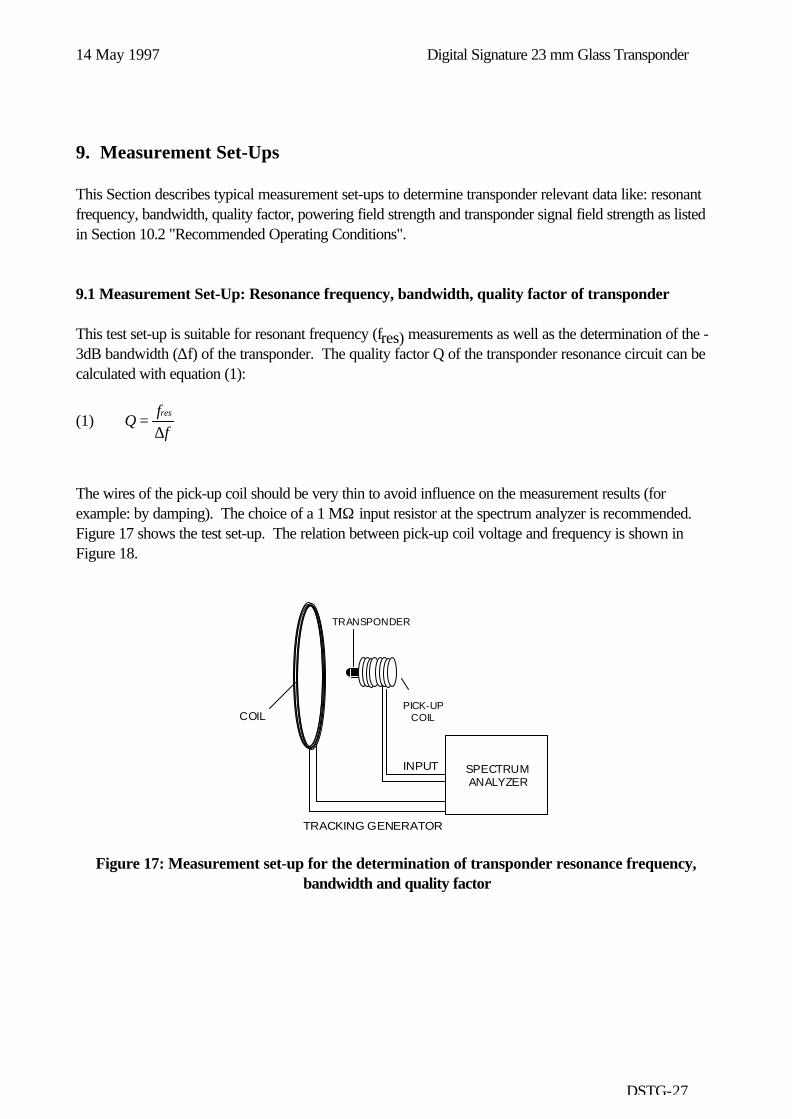
9. Measurement Set-Ups
This Section describes typical measurement set-ups to determine transponder relevant data like: resonantfrequency, bandwidth, quality factor, powering field strength and transponder signal field strength as listedin Section 10.2 "Recommended Operating Conditions".
9.1 Measurement Set-Up: Resonance frequency, bandwidth, quality factor of transponder
This test set-up is suitable for resonant frequency (fres) measurements as well as the determination of the -3dB bandwidth (∆f) of the transponder. The quality factor Q of the transponder resonance circuit can becalculated with equation (1):
(1) Qff
res=
∆
The wires of the pick-up coil should be very thin to avoid influence on the measurement results (forexample: by damping). The choice of a 1 MΩ input resistor at the spectrum analyzer is recommended.Figure 17 shows the test set-up. The relation between pick-up coil voltage and frequency is shown inFigure 18.
PICK-UP COIL
SPECTRUM ANALYZER
COIL
INPUT
TRACKING GENERATOR
TRANSPONDER
Figure 17: Measurement set-up for the determination of transponder resonance frequency,bandwidth and quality factor

Digital Signature 23 mm Glass Transponder 14 May 1997
DSTG-28
3 dB
fRes
f
UPick-upcoil
f
Figure 18: Determination of the resonance frequency and -3dB bandwidth by monitoring thepick-up coil voltage
9.2 Measurement Set-Up: Powering Field Strength
The following set-up is used to determine the minimum required powering field strength.
ANTENNA AXIS
PICK-UP COIL
SIGNALGENERATOR
d/2
d
COILS
OSCILLOSCOPETrigger
TRANSPONDER
Figure 19: Test set-up for powering field strength determination
The field between both serial connected coils is homogeneous, due to the fact that the aperture is builtaccording to the Helmholtz set-up. The circular coils are positioned in parallel on one axis. The distancebetween the coils is half the coil diameter. The transponder is positioned in the middle of the coil axis.

14 May 1997 Digital Signature 23 mm Glass Transponder
DSTG-29
Determination of the minimum powering field strength is possible by changing the field strength throughincreasing the coil current. The relation between the generated magnetic flux / field strength and coilcurrent can either be measured with a calibrated field probe, or calculated as follows:
(2) BN I
dH
o rr= ⋅ ⋅
⋅ ⋅= ⋅ ⋅
⋅45
45 2
0µ µ
µ µ/
B: magnetic flux (Tesla=Wb/m2)H: magnetic field strength (A/m)N: Number of Helmholtz Coil windingsd: Coil diameter (m)I: Coil current (A)µo: magnetic field constant (Vs/Am) = 4×p×10 -7 Vs/Amµr: relative magnetic field constant (in air: =1)
The Helmholtz set-up can be used for the specification of transponders in the temperature range from -40to +85 ºC. Tests showed, however, that deviations of the field strength caused by temperature arenegligible.
The data telegram of the transponder can be captured by a pick-up coil (for example: 10 windings, thinwire to minimize influence) which wraps the transponder. The pulse modulated signal can be adjusted atthe signal generator. The measurement of the power pulse and transponder diagram can be done with thehelp of an oscilloscope triggered by the generator signal (see Figure 19). As soon as a data telegram iscompletely detected the minimum necessary field strength (calculated with equation 2) can be monitored.
Response phasemax 15 msec
U
tWritephase
Figure 20: Received signal at the pick up coil, if power field strength is sufficient

Digital Signature 23 mm Glass Transponder 14 May 1997
DSTG-30
9.3 Measurement Set-Up: Transponder Signal Strength
The transponder has to be located into a homogeneous field (Helmholtz set-up). The pulsed power signalis generated by a signal generator. A calibrated field strength probe picks up the transponder signal. Thefield strength can be calculated by using the calibration factor of the field strength probe.
ANTENNA AXIS
PICK-UP COIL
SIGNALGENERATOR
d
COILS
SPECTRUM ANALYZER
TRANSPONDER
Figure 21: Determination of the transponder signal strength (data transmission signal strength)with Helmholtz aperture
Power andWrite phase
Readphase
U
t
Transponder signalPower signal
Noise
Figure 22: Monitored signal voltage at the spectrum analyzer (time domain mode)

14 May 1997 Digital Signature 23 mm Glass Transponder
DSTG-31
10. Specifications
10.1 Absolute Maximum Ratings
All data given for free air operating temperature range (unless otherwise noted).
PARAMETER CONDITION MIN. NOM. MAX. UNITOperating temperature(read)
Taread -40 85 oC
Operating temperature(program)
TaProg -40 85 oC
Storage temperature Ts -40 100 oCStorage temperature Ts 5 min 175 oCField strength Hexc 134.2 kHz 168 dBµA /m
10.2 Recommended Operating Conditions
All data given for free air operating temperature range, a charge time of 50 ms, and a transmitter frequencyof 134.2 kHz ± 40 Hz (unless otherwise noted).
PARAMETER SIGN NOTE MIN NOM MAX UNITTransmitter frequency fTX 134.16 134.2 134.24 kHzCharge Time tTX 15 50 msWrite Low Bit Duration tbitL 0.45 msWrite High Bit Duration tbitH 0.95 msWrite Pulse Pause/ Low Bit toffL RI-RFM-006A-
00(Note 1)
0.1 0.12 0.14 ms
Write Pulse Pause/ High Bit toffH RI-RFM-006A-00
(Note 1)
0.46 0.48 0.5 ms
Programming Time tprog 15 msProgramming ActivationFieldstrength
Hprog -40 to 85C 140.5 * dBµA/m
Programming ActivationFieldstrength
Hprog @25C 137.5 * dBµA/m
Activation Fieldstrength Hact -40 to 85C 136.5 * dBµA/mActivation Fieldstrength Hact @25C 132.5 * dBµA/mEncryption Time tenc 4 6 msRead Time tRD 15 ms
* = Preliminary
Note 1: Recommendations are only valid for RI-RFM-006A-00 [1] used in a low quality factor keylock application with tapped antenna coil circuitry [2]. Use of other RF Module circuitriesand/or reader antennas might result in minor adaption of the write timing.

Digital Signature 23 mm Glass Transponder 14 May 1997
DSTG-32
10.3 Characteristics
All data given for free air operating temperature range, a charge time of 50 ms, and a transmitter frequencyof 134.2 kHz ± 40 Hz (unless otherwise noted).
PARAMETER CONDITION MIN. NOM. MAX. UNITOperating quality factor Qop Note 1 62Allowed Q-factor drop Qdrop -3Low bit transmit frequency fL 131.5 139.0 kHzLow bit transmit frequency fL + 25 oC 132.2 134.3 136.2 kHzLow bit duration tL 0.117 0.119 0.121 msHigh bit transmitfrequency
fH 120.0 128.0 kHz
High bit transmitfrequency
fH + 25 oC 121.0 122.9 125.0 kHz
High bit duration tH 0.128 0.130 0.132 msWrite High bit detectionthreshold time
tHdet 48 ÷ fL
Transponder output fieldstrength @ 5 cm
Hout 80.5 102.5 dBµA/m
FSK Modulation index(read); fL - fH
mread + 25 oC 11 kHz
FSK Modulation index(read); fL - fH
mread 9 15 kHz
Data transmission rate(read)
rread 7.5 8.7 kbit/s
Data transmission time(read)
t read 13 15 ms
ASK modulation index(write)
mwrite 100 %
Data transmission rate,high bits (write)
rwrite Note 2 1 kbit/s
Data transmission rate, lowbits (write)
rwrite Note 2 2 kbit/s
Data transmission time twrite Note 3 36 msEncryption execution time t encx 3 ms
Note 1: Specified Qop must be met in the application over the required temperature range.Refer to the test set-up shown in figure 17.
Note 2: Adaptable to application.
Note 3: Encryption Mode.

14 May 1997 Digital Signature 23 mm Glass Transponder
DSTG-33
10.4 Environmental Data and Reliability
PARAMETER CONDITIONS MIN. NOM. MAX. UNITProgramming cycles Note 1 25 oC 10k cyclesData retention time Note 1 10k cycles
@ 25oC storagetemperature
10 years
EM Radiation immunity 1...512 MHz 100 V/mEM Radiation immunity 512..1000MHz 50 V/mESD Immunity IEC 801-2 2 kVX-ray dose 2000 RADVibration (Note 2) IEC 68-2-6, Test FcShock IEC 68-2-27, Test Ea
Note 1: Cumulative failure rate 1%.
Note 2: f = 10 - 2000 Hz.
10.5 Memory
PARAMETER DATAMemory size 88 bitsMemory organization 4 pagesIdentification data 8 bits R/W
32 bits RO
10.6 Package
PARAMETER DATADimensions 23.1 mm x 3.85 mm diameter ( see figure 3)Weight 0.6 g

Digital Signature 23 mm Glass Transponder 14 May 1997
DSTG-34
Appendix A: Conversion Formula
Conversion formula between magnetic flux, magnetic field strength and electric field strength.
B H
E Z HF
= ⋅
= ⋅
µ0
H =E
dB V / mdB A
mµµ
−
51 5. ; H =
dB Amµ ; E
dB Vm
=µ
B = magnetic flux [Tesla = Wb/m2 =Vs/m2]; 1 mWb/m2 = 0.795 A/mH = magnetic field strength [ A/m or in logarithmic term dBµA/m]E = electrical field strength [ V/m or in logarithmic term dBµV/m]µ0 = magnetic field constant = 1.257×10⁻⁶ Vs/AmZF = free space impedance = 120 π Ω = 377 Ω
Recommended