TETRAANTENNASfrom JAYBEAM

• Jaybeam have been involved with TETRA & TETRAPOL systems since their inception.
• Close co-operation with the major OEMs and system operators have resulted in a first class product range, offering real solutions to the most demanding applications.
• Full technical back up is offered with all of our range, a feature much appreciated by all customers.
• Our long experience in both Cellular and PMR radio enables us to produce the most suitable products for all frequency ranges that TETRA uses.
Recent Projects:
• ‘Airwave’ system for UK police services (currently the largest project in the world) • UK - London Underground (Motorola) • ‘Astrid’ project in Belgium (with Nokia) • UK: Inquam-Dolphin project • Ireland: ‘Barracuda for NI Police, (with Motorola) + pilot scheme for Garda (Nokia) • Many others in countries, France, Saudi Arabia, Austria, Slovenia, Croatia, Singapore,
Czech Rep. Hungary, Iceland etc.
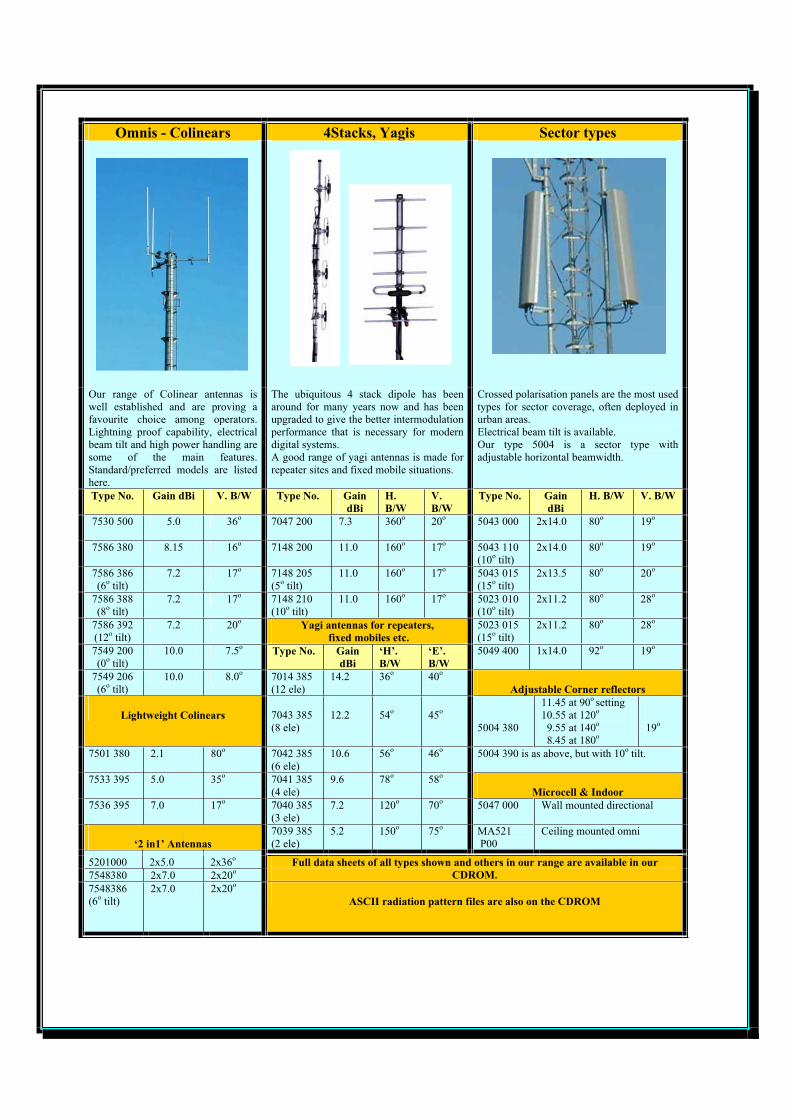
Omnis - Colinears 4Stacks, Yagis Sector types
Our range of Colinear antennas is well established and are proving a favourite choice among operators. Lightning proof capability, electrical beam tilt and high power handling are some of the main features. Standard/preferred models are listed here.
The ubiquitous 4 stack dipole has been around for many years now and has been upgraded to give the better intermodulation performance that is necessary for modern digital systems. A good range of yagi antennas is made for repeater sites and fixed mobile situations.
Crossed polarisation panels are the most used types for sector coverage, often deployed in urban areas. Electrical beam tilt is available. Our type 5004 is a sector type with adjustable horizontal beamwidth.
Type No. Gain dBi V. B/W Type No. GaindBi
H. B/W
V. B/W
Type No. GaindBi
H. B/W V. B/W
7530 500 5.0 36o 7047 200 7.3 360o 20o 5043 000 2x14.0 80o 19o
7586 380 8.15 16o 7148 200 11.0 160o 17o 5043 110 (10o tilt)
2x14.0 80o 19o
7586 386 (6o tilt)
7.2 17o 7148 205 (5o tilt)
11.0 160o 17o 5043 015 (15o tilt)
2x13.5 80o 20o
7586 388 (8o tilt)
7.2 17o 7148 210 (10o tilt)
11.0 160o 17o 5023 010 (10o tilt)
2x11.2 80o 28o
7586 392 (12o tilt)
7.2 20o Yagi antennas for repeaters, fixed mobiles etc.
5023 015 (15o tilt)
2x11.2 80o 28o
7549 200 (0o tilt)
10.0 7.5o Type No. GaindBi
‘H’. B/W
‘E’. B/W
5049 400 1x14.0 92o 19o
7549 206 (6o tilt)
10.0 8.0o 7014 385 (12 ele)
14.2 36o 40o
Adjustable Corner reflectors
Lightweight Colinears 7043 385 (8 ele)
12.2 54o 45o
5004 380
11.45 at 90o setting10.55 at 120o
9.55 at 140o
8.45 at 180o19o
7501 380 2.1 80o 7042 385 (6 ele)
10.6 56o 46o 5004 390 is as above, but with 10o tilt.
7533 395 5.0 35o 7041 385 (4 ele)
9.6 78o 58o
Microcell & Indoor 7536 395 7.0 17o 7040 385
(3 ele) 7.2 120o 70o 5047 000 Wall mounted directional
‘2 in1’ Antennas7039 385 (2 ele)
5.2 150o 75o MA521 P00
Ceiling mounted omni
5201000 2x5.0 2x36o
7548380 2x7.0 2x20oFull data sheets of all types shown and others in our range are available in our
CDROM. 7548386(6o tilt)
2x7.0 2x20o
ASCII radiation pattern files are also on the CDROM

In addition to our TETRA range, Jaybeam, in conjunction with our sister company, MAT Equipement S.A., offer antenna solutions for
most wireless systems from MF-HF through VHF –UHF –SHF up to 5.9GHz.
Base station antennas for today’s mobile systems from CDMA-AMPS through GSM 900-1800 and UMTS/3G are a major part of our business. We are in the forefront of latest developments in
this field and continue to produce a comprehensive range of excellent products.
Other active fields include, PMR - Trunked Radio – Telemetry – Paging - Ground to Air – Marine - VHF Broadcasting – DAB –
Railways - WLL and RLAN.
Mounting hardware and accessories are offered for all our antenna ranges
Jaybeam Ltd Rutherford Drive, Park Farm South, Wellingborough, Northants, England NN8 6AX Tel: +44(0) 1933 408408 Fax: +44(0) 1933 408404 Email: [email protected]
MAT Equipement S.A. ZI La Boitardiere, Chemin du Roy, 37400 Amboise, France Tel: +33(0)2 47 30 69 70 Fax: +33(0)2 47 57 35 06
www.matjaybeam.com

Jaybeam LimitedRutherford Drive, Park Farm South, Wellingborough,
Northamptonshire, NN8 6AX, EnglandTel: +44 (0) 1933 408408 Fax: +44 (0) 1933 408404
WWW jaybeam co uk
MAT EquipementZI La Boitardiere – Chemin du Roy
37400 Amboise - FranceTel: +33 (0) 2 4730 6970 Fax: +33 (0) 2 4757 3506
WWW.matequipement.com
Typical Radiation Pattern (H Plane)
Type 7530 TETRABase Station AntennaOmnidirectional ColinearLightning Proof
Type Number: 7530 500
A high quality , robust antenna that offers lightning protection.Related to our well known and highly regarded 7586 series, it is a 3dB gainversion giving a more compact size and lower imposed loadings onmounting structures.Particular attention has been given to keeping intermodulation products tothe minimum possible.
Electrical Characteristics 7530 500Frequency 380 – 400 MHzGain (max) 5.0 dBi
Power 300 W CWVSWR < 1.5:1 typical
Polarisation Linear , vertical
Horizontal Beamwidth 360ºElevation Beamwidth 36º , -3 dB point
Electrical Downtilt optional, 5 or 10degLightning Protection Will withstand pulse of 2.5 x 10⁶ A2s.
All metal parts DC groundedImpedance 50Ω
3rd Order Intermodulation < - 153dBc with 2 x 20 watt carriers
RF Termination 7/16DIN female located in the antennabase.
Mechanical CharacteristicsMaterial GRP shroud
Colour Pale Grey RAL 7035Aluminium mounting section and cap
Dimensions 1905 x 52∅ mmWeight 4.5 kg
Wind Surface area 0.10m2
Survival Windspeed In excess of 250km/hourWind Loading 130 N maximum @ 160 km/hour
General Antenna InformationNormal mounting.
reserve the right to modify or amend any antenna or specification without prior notice
Typical Radiation Pattern (E Plane)
ASCII format radiationpatterns are availableupon request.
0dB / 90
60
30
0
30
60
90
120
150
180
150
120
-2 0
-1 3
-1 0
-6
-3
-1
0dB / 90
60
30
0
30
60
90
120
150
180
150
120
-2 0
-1 3
-1 0
-6
-3
-1
(Various other clampsare available)

Jaybeam LimitedRutherford Drive, Park Farm South, Wellingborough,
Northamptonshire, NN8 6AX, EnglandTel: +44 (0) 1933 408408 Fax: +44 (0) 1933 408404
WWW jaybeam co uk
MAT EquipementZI La Boitardiere – Chemin du Roy
37400 Amboise - FranceTel: +33 (0) 2 4730 6970 Fax: +33 (0) 2 4757 3506
WWW.matequipement.com
Typical Radiation Pattern (H Plane)
Type 7586 TETRABase Station AntennaOmnidirectional ColinearLightning Proof, 0o Beam Tilt option.
Type Number: 7586 380 - 7586 390
A high quality , robust antenna that offers lightning protection.It offers wide bandwidths and due to its centre-fed dipole construction,carefully controlled radiation patterns, with the option of beamtilt.Lightning proof design makes this antenna particularly suitable for exposedsites.The high efficiency and generous power rating of the 7586 can offer manysolutions for modern trunked systems such as TETRA.
Electrical Characteristics 7586 380 7586 390RF Termination 7/16 female
located in theantenna base.
‘N’ female locatedin the antenna
base.Frequency 380 – 400 MHzGain (max) 8.15 dBi
Power 300 W CWVSWR < 1.5:1 typical
Polarisation Linear , vertical
Horizontal Beamwidth 360ºElevation Beamwidth 16º , -3 dB point
Intermodulation figures < - 153 dBc for 2 x 20watt carriersElectrical Downtilt 0o
Lightning Protection Will withstand pulse of 2.5 x 10⁶ A2s.All metal parts DC grounded
Impedance 50Ω
Mechanical CharacteristicsMaterial GRP shroud
Colour Pale Grey RAL 7035Aluminium mounting section and cap
Dimensions 3100 x 52∅ mmWeight 7.0 kg
Wind Surface area 0.14m2
Survival windspeed In excess of 250km/hourWind Loading 175 N maximum @ 160 km/hour
Rv0303
General Antenna InformationNormal mounting.
reserve the right to modify or amend any antenna or specification without prior notice
Typical Radiation Pattern (E Plane)
ASCII format radiationpatterns are availableupon request.
0dB / 90
60
30
0
30
60
90
120
150
180
150
120
-2 0
-1 3
-1 0
-6
-3
-1
0dB / 90
60
30
0
30
60
90
120
150
180
150
120
-2 0
-1 3
-1 0
-6
-3
-1

Jaybeam LimitedRutherford Drive, Park Farm South, Wellingborough,
Northamptonshire, NN8 6AX, EnglandTel: +44 (0) 1933 408408 Fax: +44 (0) 1933 408404
WWW jaybeam co uk
MAT EquipementZI La Boitardiere – Chemin du Roy
37400 Amboise - FranceTel: +33 (0) 2 4730 6970 Fax: +33 (0) 2 4757 3506
WWW.matequipement.com
Typical Radiation Pattern (H Plane)
Type 7586 TETRABase Station AntennaOmnidirectional ColinearLightning Proof, 6o Beam Tilt option.
Type Number: 7586 386 – 7586 396
A high quality , robust antenna that offers lightning protection.It offers wide bandwidths and due to its centre-fed dipole construction,carefully controlled radiation patterns, with the option of beamtilt.Lightning proof design makes this antenna particularly suitable for exposedsites.The high efficiency and generous power rating of the 7586 can offer manysolutions for modern trunked systems such as TETRA.
Electrical Characteristics 7586 386 7586 396RF Termination 7/16 female
located in theantenna base.
‘N’ female locatedin the antenna
baseFrequency 380 – 400 MHzGain (max) 7.2 dBi
Power 300 W CWVSWR < 1.5:1 typical
Polarisation Linear , vertical
Horizontal Beamwidth 360ºElevation Beamwidth 17º , -3 dB point
Electrical Downtilt 6o
Intermodulation figures < - 153 dBc for 2 x 20watt carriers
Lightning Protection Will withstand pulse of 2.5 x 10⁶ A2s.All metal parts DC grounded
Impedance 50ΩMechanical Characteristics
Material GRP shroudColour Pale Grey RAL 7035
Aluminium mounting section and capDimensions 3100 x 52∅ mm
Weight 7.0 kgWind Surface area 0.14m2
Survival Windspeed In excess of 250km/hourWind Loading 175 N maximum @ 160 km/hour
Rv0303
General Antenna InformationNormal mounting.
reserve the right to modify or amend any antenna or specification without prior notice
Typical Radiation Pattern (E Plane)
ASCII format radiationpatterns are availableupon request.
0dB / 90
60
30
0
30
60
90
120
150
180
150
120
-2 0
-1 3
-1 0
-6
-3
-1
0dB / 90
60
30
0
30
60
90
120
150
180
150
120
-2 0
-1 3
-1 0
-6
-3
-1

Jaybeam LimitedRutherford Drive, Park Farm South, Wellingborough,
Northamptonshire, NN8 6AX, EnglandTel: +44 (0) 1933 408408 Fax: +44 (0) 1933 408404
WWW jaybeam co uk
MAT EquipementZI La Boitardiere – Chemin du Roy
37400 Amboise - FranceTel: +33 (0) 2 4730 6970 Fax: +33 (0) 2 4757 3506
WWW.matequipement.com
Typical Radiation Pattern (H Plane)
Type 7586 TETRABase Station AntennaOmnidirectional ColinearLightning Proof, 8o Beam Tilt option.
Type Number: 7586 388 – 7586 398
A high quality , robust antenna that offers lightning protection.It offers wide bandwidths and due to its centre-fed dipole construction,carefully controlled radiation patterns, with the option of beamtilt.Lightning proof design makes this antenna particularly suitable for exposedsites.The high efficiency and generous power rating of the 7586 can offer manysolutions for modern trunked systems such as TETRA.
Electrical Characteristics 7586 388 7586 398RF Termination 7/16 female
located in theantenna base.
‘N’ female locatedin the antenna
baseFrequency 380 – 400 MHzGain (max) 7.2 dBi
Power 300 W CWVSWR < 1.5:1 typical
Polarisation Linear , vertical
Horizontal Beamwidth 360ºElevation Beamwidth 17º , -3 dB point
Electrical Downtilt 8o
Intermodulation figures < -153dBc for 2 x 20 watt carriers
Lightning Protection Will withstand pulse of 2.5 x 10⁶ A2s.All metal parts DC grounded
Impedance 50ΩMechanical Characteristics
Material GRP shroudColour Pale Grey RAL 7035
Aluminium mounting section and capDimensions 3100 x 52∅ mm
Weight 7.0 kgWind Surface area 0.14m2
Survival Windspeed In excess of 250km/hourWind Loading 175 N maximum @ 160 km/hour
Rv0303
General Antenna InformationNormal mounting.
reserve the right to modify or amend any antenna or specification without prior notice
Typical Radiation Pattern (E Plane)
ASCII format radiationpatterns are availableupon request.
0dB / 90
60
30
0
30
60
90
120
150
180
150
120
-2 0
-1 3
-1 0
-6
-3
-1
0dB / 90
60
30
0
30
60
90
120
150
180
150
120
-2 0
-1 3
-1 0
-6
-3
-1

Jaybeam LimitedRutherford Drive, Park Farm South, Wellingborough,
Northamptonshire, NN8 6AX, EnglandTel: +44 (0) 1933 408408 Fax: +44 (0) 1933 408404
WWW jaybeam co uk
MAT EquipementZI La Boitardiere – Chemin du Roy
37400 Amboise - FranceTel: +33 (0) 2 4730 6970 Fax: +33 (0) 2 4757 3506
WWW.matequipement.com
Typical Radiation Pattern (H Plane)
Type 7586 TETRABase Station AntennaOmnidirectional ColinearLightning Proof, 12o Beam Tilt option.
Type Number: 7586 392 – 7586 382
A high quality , robust antenna that offers lightning protection.It offers wide bandwidths and due to its centre-fed dipole construction,carefully controlled radiation patterns, with the option of beamtilt.Lightning proof design makes this antenna particularly suitable for exposedsites.The high efficiency and generous power rating of the 7586 can offer manysolutions for modern trunked systems such as TETRA.
Electrical Characteristics 7586 392 7586 382RF Termination 7/16 female
located in theantenna base.
‘N’ female locatedin the antenna
base.Frequency 380 – 400 MHzGain (max) 7.2 dBi
Power 300 W CWVSWR < 1.5:1 typical
Polarisation Linear , vertical
Horizontal Beamwidth 360ºElevation Beamwidth 20º , -3 dB point
Electrical Downtilt 12o
Intermodulation figures < -153dBc for 2 x 20watt carriers
Lightning Protection Will withstand pulse of 2.5 x 10⁶ A2s.All metal parts DC grounded
Impedance 50ΩMechanical Characteristics
Material GRP shroudColour Pale Grey RAL 7035
Aluminium mounting section and capDimensions 3100 x 52∅ mm
Weight 7.0 kgWind Surface area 0.14m2
Survival Windspeed In excess of 250km/hourWind Loading 175 N maximum @ 160 km/hour
Rv0303
General Antenna InformationNormal mounting.
reserve the right to modify or amend any antenna or specification without prior notice
Typical Radiation Pattern (E Plane)
ASCII format radiationpatterns are availableupon request.
0dB / 90
60
30
0
30
60
90
120
150
180
150
120
-2 0
-1 3
-1 0
-6
-3
-1
0dB / 90
60
30
0
30
60
90
120
150
180
150
120
-2 0
-1 3
-1 0
-6
-3
-1

Jaybeam LimitedRutherford Drive, Park Farm South, Wellingborough,
Northamptonshire, NN8 6AX, EnglandTel: +44 (0) 1933 408408 Fax: +44 (0) 1933 408404
WWW jaybeam co uk
MAT EquipementZI La Boitardiere – Chemin du Roy
37400 Amboise - FranceTel: +33 (0) 2 4730 6970 Fax: +33 (0) 2 4757 3506
WWW.matequipement.com
Typical Radiation Pattern (H Plane)
Type 7549 TETRABase Station AntennaOmnidirectional Colinear, High GainLightning Proof, Beam Tilt option.
Type Number: 7549 200
A high quality , robust and unobtrusive antenna that offers lightningprotection.It offers wide bandwidths and due to its centre-fed dipole construction,carefully controlled radiation patterns, with the option of beamtilt.Lightning proof design makes this antenna particularly suitable for exposedsites. The high efficiency and generous power rating of the 7549 can offermany solutions for modern trunked systems such as TETRA.
Electrical Characteristics 7549 200Frequency 380-400 MHzGain (max) 10.0 dBi
Power 300 W CWVSWR < 1.5:1 typical
Polarisation Linear , vertical
Horizontal Beamwidth 360ºElevation Beamwidth 7.5º , -3 dB point
Electrical Downtilt Oo
Lightning Protection Will withstand pulse of 2.5 x 10⁶ A2s.All metal parts DC grounded, metal cap
3rd order Intermodulation _- 148dBc for 2 x 20 watt carriersImpedance 50Ω
RF Termination N female or 7/16 DIN female ondownlead
Mechanical CharacteristicsMaterial GRP shroud
Colour Pale Grey RAL 7035Aluminium mounting section (70mm∅)
dDimensions 5400 x 57∅ mmWeight 12.0 kg
Max operational wind speed 260 km/hrWind Loading 380 N maximum @ 160 km/hour
Rv0403
General Antenna InformationNormal mounting.
reserve the right to modify or amend any antenna or specification without prior notice
Typical Radiation Pattern (E Plane)
ASCII format radiationpatterns are availableupon request.
0dB / 90
60
30
0
30
60
90
120
150
180
150
120
-2 0
-1 3
-1 0
-6
-3
-1
0dB / 90
60
30
0
30
60
90
120
150
180
150
120
-2 0
-1 3
-1 0
-6
-3
-1
Clamps to fit pipes of115mm∅∅

Jaybeam LimitedRutherford Drive, Park Farm South, Wellingborough,
Northamptonshire, NN8 6AX, EnglandTel: +44 (0) 1933 408408 Fax: +44 (0) 1933 408404
WWW jaybeam co uk
MAT EquipementZI La Boitardiere – Chemin du Roy
37400 Amboise - FranceTel: +33 (0) 2 4730 6970 Fax: +33 (0) 2 4757 3506
WWW.matequipement.com
Typical Radiation Pattern (H Plane)
Type 7549 TETRABase Station AntennaOmnidirectional Colinear, High GainLightning Proof, 6o Beam Tilt
Type Number: 7549 206
A high quality , robust and unobtrusive antenna that offers lightningprotection.It offers wide bandwidths and due to its centre-fed dipole construction,carefully controlled radiation patterns, with the option of beamtilt.Lightning proof design makes this antenna particularly suitable for exposedsites. The high efficiency and generous power rating of the 7549 can offermany solutions for modern trunked systems such as TETRA.
Electrical Characteristics 7549 206Frequency 380 – 400 MHzGain (max) 11.0 dBi
Power 300 W CWVSWR < 1.5:1 typical
Polarisation Linear , vertical
Horizontal Beamwidth 360ºElevation Beamwidth 7.5º , -3 dB point
Electrical Downtilt 6o
Lightning Protection Will withstand pulse of 2.5 x 10⁶ A2s.All metal parts DC grounded
3rd Order Intermodulation -148dBc for 2 x 20 watt carriersImpedance 50Ω
RF Termination 7/16 female
Mechanical CharacteristicsMaterial GRP shroud
Colour Pale Grey RAL 7035Aluminium mounting section and cap
Dimensions 5400 x 60∅ mmWeight 12.0 kg
Wind Surface area 0.3m2
Wind Loading 380 N maximum @ 160 km/hourRv0403
General Antenna InformationNormal mounting.
reserve the right to modify or amend any antenna or specification without prior notice
Typical Radiation Pattern (E Plane)
ASCII format radiationpatterns are availableupon request.
0dB / 90
60
30
0
30
60
90
120
150
180
150
120
-2 0
-1 3
-1 0
-6
-3
-1
0dB / 90
60
30
0
30
60
90
120
150
180
150
120
-2 0
-1 3
-1 0
-6
-3
-1
Clamps to fit pipes of115mm∅∅

Jaybeam LimitedRutherford Drive, Park Farm South, Wellingborough,
Northamptonshire, NN8 6AX, EnglandTel: +44 (0) 1933 408408 Fax: +44 (0) 1933 408404
WWW jaybeam co uk WWW.matequipement.com
Typical Radiation Pattern (H Plane)
Type 7501Base Station / Fixed Mobile AntennaOmnidirectional Dipole
Type Number: 7501
One of our most popular antennas, the 7501 finds applications in manyareas.Highly efficient, it is ideal for low power applications as well as everydayPMR and TETRA situationsIt offers wide bandwidths and due to its centre-fed dipole construction,carefully controlled radiation pattern
Electrical Characteristics 7501 ***Frequency 7501 380
7501 4507501 470
380 – 430 MHz420-470,MHz450-500 MHz
Gain (max) 2.15 dBiPower 150 W CWVSWR < 1.5:1 typical
Polarisation Linear , vertical
Horizontal Beamwidth 360º
Elevation Beamwidth 80º , -3 dB point
Lightning Protection All metal parts DC grounded
Impedance 50ΩRF Termination N female fitted to 0.3m RG213 Coaxial
Cable Downlead. (7/16 DIN Optional).
All antennas are DC Grounded
Mechanical CharacteristicsMaterial GRP shroud
Colour WhiteAlochromed Aluminium mountingsection with Stainless Steel Fixings
Dimensions 605mm x 21∅ mmWeight 0.9 kg
Wind Surface area 0.012m2
Wind Loading 16 N maximum @ 160 km/hourGeneral Antenna InformationMounting: Integral mounting clamp allows fixing to 50mmdiameter pipes or horizontal rail.Can be supplied with wall mounting to special order.
reserve the right to modify or amend any antenna or specification without prior notice
Typical Radiation Pattern (E Plane)
ASCII format radiationpatterns are availableupon request.
0dB / 90
60
30
0
30
60
90
120
150
180
150
120
-2 0
-1 3
-1 0
-6
-3
-1
0dB / 90
60
30
0
30
60
90
120
150
180
150
120
-2 0
-1 3
-1 0
-6
-3
-1
MAT EquipementZI La Boitardiere – Chemin du Roy
37400 Amboise - FranceTel: +33 (0) 2 4730 6970 Fax: +33 (0) 2 4757 3506

Jaybeam LimitedRutherford Drive, Park Farm South, Wellingborough,
Northamptonshire, NN8 6AX, EnglandTel: +44 (0) 1933 408408 Fax: +44 (0) 1933 408404
WWW jaybeam co uk WWW.matequipement.com
Typical Radiation Pattern (H Plane)
Type 7533 ***UHF Band Base Station3 dBd Gain Colinear
Type Number: 7533
This antenna is long established and carries R.A. type approval for UHFtelemetry systems (MPT 1411). It is also finding favour with TETRAoperators.Highly efficient, it is easily mounted using the integrated clamp, ontovertical poles or horizontal rails.It offers wide bandwidths and due to its centre-fed dipole construction,carefully controlled radiation pattern
Electrical Characteristics 7533 ***FrequencyVersions
380-410, 400-440420-450, 430-470, 490-510 MHz
Gain (max) 3.0 dBdPower 150 W CWVSWR < 1.5:1 typical
Polarisation Linear , vertical
Horizontal Beamwidth 360º
Elevation Beamwidth 35º , -3 dB point
Lightning Protection All metal parts DC grounded
Impedance 50ΩRF Termination N female fitted to 0.3m RG213 Coaxial
Cable Downlead. (7/16 DIN Optional).
All antennas are DC Grounded
Mechanical CharacteristicsMaterial GRP shroud
Colour WhiteAlochromed Aluminium mountingsection with Stainless Steel Fixings
Length 1500mmWeight 1.1 kg
Wind Surface area 0.0255m2
Wind Loading 35 N maximum @ 160 km/hourGeneral Antenna InformationMounting: Integral mounting clamp allows fixing to 50mmdiameter pipes or horizontal rail.
reserve the right to modify or amend any antenna or specification without prior notice
Typical Radiation Pattern (E Plane)
ASCII format radiationpatterns are availableupon request.
0dB / 90
60
30
0
30
60
90
120
150
180
150
120
-2 0
-1 3
-1 0
-6
-3
-1
0dB / 90
60
30
0
30
60
90
120
150
180
150
120
-2 0
-1 3
-1 0
-6
-3
-1
MAT EquipementZI La Boitardiere – Chemin du Roy
37400 Amboise - FranceTel: +33 (0) 2 4730 6970 Fax: +33 (0) 2 4757 3506

Jaybeam LimitedRutherford Drive, Park Farm South, Wellingborough,
Northamptonshire, NN8 6AX, EnglandTel: +44 (0) 1933 408408 Fax: +44 (0) 1933 408404
WWW jaybeam co uk WWW.matequipement.com
Typical Radiation Pattern (H Plane)
Type 7536 ***UHF Band Base StationHigh Gain Colinear
Type Number: 7536
This antenna is long established and carries R.A. type approval for UHFtelemetry systems (MPT 1411). It is also finding favour with TETRAoperators.Highly efficient, it is easily mounted using the integrated clamp, ontovertical poles or horizontal rails.It offers wide bandwidths and due to its centre-fed dipole construction,carefully controlled radiation pattern
Electrical Characteristics 7536 ***FrequencyVersions
380-400, 400-430420-450, 440-470 MHz
Gain (max) 5.5 dBdPower 150 W CWVSWR < 1.5:1 typical
Polarisation Linear , vertical
Horizontal Beamwidth 360º
Elevation Beamwidth 17º , -3 dB point
Lightning Protection All metal parts DC grounded
Impedance 50ΩRF Termination N female fitted to 0.3m RG213 Coaxial
Cable Downlead. (7/16 DIN Optional).
All antennas are DC Grounded
Mechanical CharacteristicsMaterial GRP shroud
Colour WhiteAlochromed Aluminium mountingsection with Stainless Steel Fixings
Length 2700mmWeight 1.8 kg
Wind Surface area 0.054m2
Wind Loading 73 N maximum @ 160 km/hourGeneral Antenna InformationMounting: Integral mounting clamp allows fixing to 50mmdiameter pipes or horizontal rail.
reserve the right to modify or amend any antenna or specification without prior notice
Typical Radiation Pattern (E Plane)
ASCII format radiationpatterns are availableupon request.
0dB / 90
60
30
0
30
60
90
120
150
180
150
120
-2 0
-1 3
-1 0
-6
-3
-1
0dB / 90
60
30
0
30
60
90
120
150
180
150
120
-2 0
-1 3
-1 0
-6
-3
-1
MAT EquipementZI La Boitardiere – Chemin du Roy
37400 Amboise - FranceTel: +33 (0) 2 4730 6970 Fax: +33 (0) 2 4757 3506

Typical Radiation Pattern (H Plane)
Type 5201 Two in OneTETRA Base Station AntennaOmnidirectional Colinears, Medium GainLightning Proof.
Type Number: 5201 000
A high quality , robust and unobtrusive antenna that offers two separateomnidirectional colinear antennas in one slim housing.Good isolation between the antennas allow for diversity.Lightning proof design makes this antenna particularly suitable for exposedsites. The ascetic appearance can contribute to an unobtrusive site, oftennecessary in these environmentally sensitive times.
Electrical Characteristics 5201 000Frequency 380-400 MHzGain TopBottom
4.9dBi5.0dBi
Power 300 W each portVSWR < 1.4:1 typical
Polarisation Linear , vertical
Horizontal Beamwidth 360ºElevation Beamwidth 36o , -3 dB point
Isolation between ports < 27 dBIntermodulation
( 3rd Order)< -153dBc for 2 x 20watt carriers
Lightning Protection Will withstand pulse of 2.5 x 10⁶ A2s.All metal parts DC grounded
Impedance 50ΩRF Termination 2x 7/16 DIN female on cable
downleadsMechanical Characteristics
Material GRP shroudColour Pale Grey RAL 7035
Aluminium mounting section and capDimensions 3160 x 52∅ mm
Weight 7.0 kgWind Loading 180 N maximum @ 160 km/hour
General Antenna InformationNormal mounting.
reserve the right to modify or amend any antenna or specification without prior notice
Typical Radiation Pattern (E Plane)
ASCII format radiationpatterns are availableupon request.
0dB / 90
60
30
0
30
60
90
120
150
180
150
120
-2 0
-1 3
-1 0
-6
-3
-1
Clamps to fit pipes of115mm∅∅ are available.
0dB / 90
60
30
0
30
60
90
120
150
180
150
120
-2 0
-1 3
-1 0
-6
-3
-1
Jaybeam LimitedRutherford Drive, Park Farm South, Wellingborough,
Northamptonshire, NN8 6AX, EnglandTel: +44 (0) 1933 408408 Fax: +44 (0) 1933 408404
WWW.jaybeam.co.uk
MAT EquipementZI La Boitardiere – Chemin du Roy
37400 Amboise - FranceTel: +33 (0) 2 4730 6970 Fax: +33 (0) 2 4757 3506
WWW.matequipement.com

Jaybeam LimitedRutherford Drive, Park Farm South, Wellingborough,
Northamptonshire, NN8 6AX, England Tel: +44 (0) 1933 408408 Fax: +44 (0) 1933 408404
WWW.jaybeam.co.uk
MAT EquipementZI La Boitardiere – Chemin du Roy
37400 Amboise - France Tel: +33 (0) 2 4730 6970 Fax: +33 (0) 2 4757 3506
WWW.matequipement.com
Typical Radiation Pattern (H Plane)
Type 7548 Two in One TETRA Base Station Antenna Omnidirectional Colinear, Good Isolation. Lightning Proof. High Gain. 0o tilt
Type Number: 7548 380
A high quality , robust and unobtrusive antenna that offers two separate Hi-gain omnidirectional antennas in one slim housing. Good isolation between the antennas allow for diversity. Lightning proof design makes this antenna particularly suitable for exposed sites. The ascetic appearance can contribute to an unobtrusive base site, often necessary in these environmentally sensitive times.
Electrical Characteristics 7548 380 Frequency 380 – 400 MHz Gain Top Bottom
6.4 dBi 7.3 dBi
Power 300 W CW (each port)VSWR < 1.4:1 maximum
Polarisation Linear , vertical
Horizontal Beamwidth 360º Elevation Beamwidth 20.5º , -3 dB point
Electrical Downtilt 0o
Isolation between antennas < 37 dB Lightning Protection Will withstand pulse of 2.5 x 10⁶ A2s.
All metal parts DC grounded Impedance 50
RF Termination 2 x 7/16 female on cable downleads
Mechanical CharacteristicsMaterial GRP shroud
Colour White Aluminium mounting section and cap
Dimensions 5780 x 60 mm Weight 12.5 kg
Wind Surface area 0.30m2
Wind Loading 430 N maximum @ 160 km/hour
General Antenna InformationNormal mounting.
reserve the right to modify or amend any antenna or specification without prior notice
Typical Radiation Pattern (E Plane)
ASCII format radiation patterns are available upon request.
0dB / 90
60
30
0
30
60
90
120
150
180
150
120
-2 0
-1 3
-1 0
-6
-3
-1
0dB / 90
60
30
0
30
60
90
120
150
180
150
120
-2 0
-1 3
-1 0
-6
-3
-1
Clamps to fit pipes of 115mm

Jaybeam LimitedRutherford Drive, Park Farm South, Wellingborough,
Northamptonshire, NN8 6AX, England Tel: +44 (0) 1933 408408 Fax: +44 (0) 1933 408404
WWW.jaybeam.co.uk
MAT EquipementZI La Boitardiere – Chemin du Roy
37400 Amboise - France Tel: +33 (0) 2 4730 6970 Fax: +33 (0) 2 4757 3506
WWW.matequipement.com
Typical Radiation Pattern (H Plane)
Type 7548 Two in One TETRA Base Station Antenna Omnidirectional Colinear, Good Isolation. Lightning Proof. High Gain. 6o tilt
Type Number: 7548 386
A high quality , robust and unobtrusive antenna that offers two separate Hi-gain omnidirectional antennas in one slim housing. Good isolation between the antennas allow for diversity. Lightning proof design makes this antenna particularly suitable for exposed sites. The ascetic appearance can contribute to an unobtrusive base site, often necessary in these environmentally sensitive times.
Electrical Characteristics 7548 386 Frequency 380 – 400 MHz Gain Top Bottom
6.4 dBi 7.3 dBi
Power 300 W CW (each port)VSWR < 1.4:1 maximum
Polarisation Linear , vertical
Horizontal Beamwidth 360º Elevation Beamwidth 16.5º , -3 dB point
Electrical Downtilt 6o
Isolation between antennas < 37 dB Lightning Protection Will withstand pulse of 2.5 x 10⁶ A2s.
All metal parts DC grounded Impedance 50
RF Termination 2 x 7/16 female on cable downleads
Mechanical CharacteristicsMaterial GRP shroud
Colour White Aluminium mounting section and cap
Dimensions 5780 x 60 mm Weight 12.5 kg
Wind Surface area 0.30m2
Wind Loading 430 N maximum @ 160 km/hour
General Antenna InformationNormal mounting.
reserve the right to modify or amend any antenna or specification without prior notice
Typical Radiation Pattern (E Plane)
ASCII format radiation patterns are available upon request.
0dB / 90
60
30
0
30
60
90
120
150
180
150
120
-2 0
-1 3
-1 0
-6
-3
-1
0dB / 90
60
30
0
30
60
90
120
150
180
150
120
-2 0
-1 3
-1 0
-6
-3
-1
Clamps to fit pipes of 115mm

Jaybeam LimitedRutherford Drive, Park Farm South, Wellingborough,
Northamptonshire, NN8 6AX, EnglandTel: +44 (0) 1933 408408 Fax: +44 (0) 1933 408404
WWW jaybeam co uk
MAT EquipementZI La Boitardiere – Chemin du Roy
37400 Amboise - FranceTel: +33 (0) 2 4730 6970 Fax: +33 (0) 2 4757 3506
WWW.matequipement.com
Typical Radiation Pattern (H Plane)
Type 7047 TETRABase Station AntennaOmnidirectional 4 stacked dipolesUpgraded for better Intermodulation figures
Type Number: 7047 200
This antenna, one of our well-established 4 stack dipoles, has beenupgraded to improve intermodulation performance for today’s digitalPMR systems such as TETRA.Operating frequency is the TETRA band, (380-430MHz.)The rugged construction and high quality components used ensure along and reliable service life.
Electrical Characteristics 7047 200Frequency 380 – 430 MHzMax Gain 5.2dBd, 7.3 dBi
Power 200 W CWVSWR < 1.5:1 typical
Polarisation Linear , vertical
Horizontal Beamwidth 360º -3 dB pointElevation Beamwidth 20º , -3 dB point
Intermodulation Performance < -145 dBc for 2 x 20watt carriers
Lightning Protection All metal parts DC grounded
Impedance 50ΩRF Termination 7/16 female on RG214 Downlead.
Mechanical CharacteristicsConstruction Centre fed folded dipoles, (with baluns)
fixed on a one piece vertical boom.Dipoles are able to be rotated on the
boom to allow for omni or directionalmode.
Dimensions 2600 x 132 x 110 mmWeight 7.0 kg
Wind Surface area 0.14m2
Wind Loading 190 N maximum @ 45m/sec
General Antenna InformationNormal mounting.Either clamped at bottom, or fixed top and bottom, stood off the side of a radio mast.Will also drop into a standard size(48.4mm) scaffolding pole.
Jaybeam reserve the right to modify or amend any antenna or specification without prior notice
Typical Radiation Pattern (E Plane)
ASCII format radiationpatterns are availableupon request.
0dB / 90
60
30
0
30
60
90
120
150
180
150
120
-2 0
-1 3
-1 0
-6
-3
-1
0dB / 90
60
30
0
30
60
90
120
150
180
150
120
-2 0
-1 3
-1 0
-6
-3
-1

Jaybeam LimitedRutherford Drive, Park Farm South, Wellingborough,
Northamptonshire, NN8 6AX, EnglandTel: +44 (0) 1933 408408 Fax: +44 (0) 1933 408404
WWW jaybeam co uk
MAT EquipementZI La Boitardiere – Chemin du Roy
37400 Amboise - FranceTel: +33 (0) 2 4730 6970 Fax: +33 (0) 2 4757 3506
WWW.matequipement.com
Typical Radiation Pattern (H Plane)
Type 7148 TETRADirectional 4 stacked dipolesUpgraded intermodulation performanceLightning Proof, 0o Beam Tilt option.
Type Number: 7148 200
This antenna, one of our well-established 4 stack dipoles, has beenupgraded to improve intermodulation performance for today’s digitalPMR systems such as TETRA.Operating frequency is the TETRA band, (380-430MHz.)The rugged construction and high quality components used ensure along and reliable service life.
Electrical Characteristics 7148 200Frequency 380 – 430 MHz
Max Gain (directional) 9.0dBd, 11.0 dBiPower 200 W CWVSWR < 1.5:1 typical
Polarisation Linear , vertical
Horizontal Beamwidth 160º -3 dB pointElevation Beamwidth 17º , -3 dB point
Intermodulation Performance < -143 dBc for 2 x 20watt carriersElectrical Downtilt 0o
Lightning Protection All metal parts DC grounded
Impedance 50ΩRF Termination 7/16 DIN female on RG214 Downlead.
Mechanical CharacteristicsConstruction Centre fed folded dipoles, (with baluns)
fixed on a one piece vertical boom.Dipoles are able to be rotated on the
boom to allow for omni or directionalmode.
Dimensions 2600 x 132 x 110 mmWeight 7.0 kg
Wind Surface area 0.14m2
Wind Loading 190 N maximum @ 45m/sec
General Antenna InformationNormal mounting.Either clamped at bottom, or fixed top and bottom, stood off the side of a radio mast.Will also drop into a standard size(48.4mm) scaffolding pole.
reserve the right to modify or amend any antenna or specification without prior notice
Typical Radiation Pattern (E Plane)
ASCII format radiationpatterns are availableupon request.
0dB /90
60
30
0
30
60
90
120
150
180
150
120
-2
0
- 3
-1
0
-6
-3
-1
0dB / 90
60
30
0
30
60
90
120
150
180
150
120
-2 0
-1 3
-1 0
-6
-3
-1

Jaybeam LimitedRutherford Drive, Park Farm South, Wellingborough,
Northamptonshire, NN8 6AX, EnglandTel: +44 (0) 1933 408408 Fax: +44 (0) 1933 408404
WWW jaybeam co uk
MAT EquipementZI La Boitardiere – Chemin du Roy
37400 Amboise - FranceTel: +33 (0) 2 4730 6970 Fax: +33 (0) 2 4757 3506
WWW.matequipement.com
Typical Radiation Pattern (H Plane)
Type 7148 TETRADirectional 4 stacked dipolesUpgraded intermodulation performanceLightning Proof, 5o Beam Tilt option.
Type Number: 7148 205
This antenna, one of our well-established 4 stack dipoles, has beenupgraded to improve intermodulation performance for today’s digitalPMR systems such as TETRA.Operating frequency is the TETRA band, (380-430MHz.)The rugged construction and high quality components used ensure along and reliable service life.
Electrical Characteristics 7148 205Frequency 380 – 430 MHz
Max Gain (directional) 9.0dBd, 11.0 dBiPower 200 W CWVSWR < 1.5:1 typical
Polarisation Linear , vertical
Horizontal Beamwidth 160º -3 dB pointElevation Beamwidth 17º , -3 dB point
Intermodulation Performance < -143 dBc for 2 x 20watt carriersElectrical Downtilt 5o
Lightning Protection All metal parts DC grounded
Impedance 50ΩRF Termination 7/16 DIN female on RG214 Downlead.
Mechanical CharacteristicsConstruction Centre fed folded dipoles, (with baluns)
fixed on a one piece vertical boom.Dipoles are able to be rotated on the
boom to allow for omni or directionalmode.
Dimensions 2600 x 132 x 110 mmWeight 7.0 kg
Wind Surface area 0.14m2
Wind Loading 190 N maximum @ 45m/sec
General Antenna InformationNormal mounting.Either clamped at bottom, or fixed top and bottom, stood off the side of a radio mast.Will also drop into a standard size(48.4mm) scaffolding pole.
reserve the right to modify or amend any antenna or specification without prior notice
Typical Radiation Pattern (E Plane)
ASCII format radiationpatterns are availableupon request.
0dB / 90
60
30
0
30
60
90
120
150
180
150
120
-2 0
-1 3
-1 0
-6
-3
-1
0dB / 90
60
30
0
30
60
90
120
150
180
150
120
-2 0
-1 3
-1 0
-6
-3
-1

Jaybeam LimitedRutherford Drive, Park Farm South, Wellingborough,
Northamptonshire, NN8 6AX, EnglandTel: +44 (0) 1933 408408 Fax: +44 (0) 1933 408404
WWW jaybeam co uk
MAT EquipementZI La Boitardiere – Chemin du Roy
37400 Amboise - FranceTel: +33 (0) 2 4730 6970 Fax: +33 (0) 2 4757 3506
WWW.matequipement.com
Typical Radiation Pattern (H Plane)
Type 7148 TETRADirectional 4 stacked dipolesUpgraded intermodulation performanceLightning Proof, 10o Beam Tilt option.
Type Number: 7148 210
This antenna, one of our well-established 4 stack dipoles, has beenupgraded to improve intermodulation performance for today’s digitalPMR systems such as TETRA.Operating frequency is the TETRA band, (380-430MHz.)The rugged construction and high quality components used ensure along and reliable service life.
Electrical Characteristics 7148 210Frequency 380 – 430 MHz
Max Gain (directional) 9.0dBd, 11.0 dBiPower 200 W CWVSWR < 1.5:1 typical
Polarisation Linear , vertical
Horizontal Beamwidth 160º -3 dB pointElevation Beamwidth 17º , -3 dB point
Intermodulation Performance < -143 dBc for 2 x 20watt carriersElectrical Downtilt 10o
Lightning Protection All metal parts DC grounded
Impedance 50ΩRF Termination 7/16 DIN female on RG214 Downlead.
Mechanical CharacteristicsConstruction Centre fed folded dipoles, (with baluns)
fixed on a one piece vertical boom.Dipoles are able to be rotated on the
boom to allow for omni or directionalmode.
Dimensions 2600 x 132 x 110 mmWeight 7.0 kg
Wind Surface area 0.14m2
Wind Loading 190 N maximum @ 45m/sec
General Antenna InformationNormal mounting.Either clamped at bottom, or fixed top and bottom, stood off the side of a radio mast.Will also drop into a standard size(48.4mm) scaffolding pole.
reserve the right to modify or amend any antenna or specification without prior notice
Typical Radiation Pattern (E Plane)
ASCII format radiationpatterns are availableupon request.
0dB / 90
60
30
0
30
60
90
120
150
180
150
120
-2 0
-1 3
-1 0
-6
-3
-1
0dB / 90
60
30
0
30
60
90
120
150
180
150
120
-2 0
-1 3
-1 0
-6
-3
-1

Jaybeam LimitedRutherford Drive, Park Farm South, Wellingborough,
Northamptonshire, NN8 6AX, EnglandTel: +44 (0) 1933 408408 Fax: +44 (0) 1933 408404
WWW jaybeam co uk
MAT EquipementZI La Boitardiere – Chemin du Roy
37400 Amboise - FranceTel: +33 (0) 2 4730 6970 Fax: +33 (0) 2 4757 3506
WWW.matequipement.com
Typical Radiation Pattern (E Plane)
Type 7014UHF 12 Element Yagi, TETRAHigh Gain end mounted.Upgraded for enhanced IMP
Electrical Characteristics 7014 385Frequency 380 – 400 MHzBandwidth ± 4% (typical)Gain (max) 12.0 dBd (14.2dBi)
Power 150 WattsVSWR < 1.5:1 typical
Polarisation Linear, Vertical or Horizontal
‘H’ Plane Beamwidth 36º, -3 dB point
‘E’ Plane Beamwidth 40º, -3 dB point
Front to Back Ratio >25dB (typical)
Impedance 50ΩTerminations 7/16 DIN female, on 3m downlead of
RG214 Coaxial Cable
3rd order intermod figures < -145dBc for 2 x 10watt carriersAll antennas are DC Grounded
Mechanical CharacteristicsMaterial Boom, 32mm∅ Aluminium
Elements, 12.5mm∅ DrawnAluminium tube. Balun, Inverse type,
moulded.Length 2420 mmWeight 5.2 kg excluding mounting hardware.
Wind Loading 145 N maximum @ 45m/secRv0403
General Antenna Information
0dB / 90
60
30
0
30
60
90
120
150
180
150
120
-2 0
-1 3
-1 0
-6
-3
-1
Mounting Accessories:Recommended clamps:9078/9, 9174, 9112 or 99364(fits 50mm or 75mm poles)
reserve the right to modify or amend any antenna or specification without prior notice
Typical Radiation Pattern (H Plane)
ASCII format radiationpatterns are availableupon request.
0dB / 90
60
30
0
30
60
90
120
150
180
150
120
-2 0
-1 3
-1 0
-6
-3
-1
Type Number 7014 385
A 12-element yagi antennalong established in ourrange.Ideal for repeaters andfixed mobile use, it has asuperb radiation patternand has been carefullyoptimised to give ultimateperformance for this type.This version has upgradedintermodulationperformance for modernTETRA systems.

Jaybeam LimitedRutherford Drive, Park Farm South, Wellingborough,
Northamptonshire, NN8 6AX, EnglandTel: +44 (0) 1933 408408 Fax: +44 (0) 1933 408404
WWW jaybeam co uk
MAT EquipementZI La Boitardiere – Chemin du Roy
37400 Amboise - FranceTel: +33 (0) 2 4730 6970 Fax: +33 (0) 2 4757 3506
WWW.matequipement.com
Typical Radiation Pattern (E Plane)
Type 7043UHF 8 Element Yagi, TETRAHigh Gain end mounted.Upgraded for enhanced IMP
Electrical Characteristics 7043 385Frequency 380 – 400 MHzBandwidth ± 4% (typical)Gain (max) 10.0 dBd (12.2dBi)
Power 150 WattsVSWR < 1.5:1 typical
Polarisation Linear, Vertical or Horizontal
‘H’ Plane Beamwidth 54º, -3 dB point
‘E’ Plane Beamwidth 45º, -3 dB point
Front to Back Ratio >22dB (typical)
Impedance 50ΩTerminations 7/16 DIN female, on 3m downlead of
RG214 Coaxial Cable
3rd order intermod figures < -145dBc for 2 x 10watt carriersAll antennas are DC Grounded
Mechanical CharacteristicsMaterial Boom, 32mm∅ Aluminium
Elements, 12.5mm∅ DrawnAluminium tube. Balun, Inverse type,
moulded.Length (@450MHz) 1270 mmWeight (@450MHz) 4.0 kg excluding mounting hardware.
Wind Loading (@450MHz) 92 N maximum @ 45m/secRv0403
General Antenna Information
0dB / 90
60
30
0
30
60
90
120
150
180
150
120
-2 0
-1 3
-1 0
-6
-3
-1
Mounting Accessories:Recommended clamps:9078/9, 9174, 9112 or 99364(fits 50mm or 75mm poles)
reserve the right to modify or amend any antenna or specification without prior notice
Typical Radiation Pattern (H Plane)
ASCII format radiationpatterns are availableupon request.
0dB / 90
60
30
0
30
60
90
120
150
180
150
120
-2 0
-1 3
-1 0
-6
-3
-1
Type Number 7043 385
An 8-element yagi antennalong established in ourrange.It offers the ultimateperformance for this typeand carries UK R.A.approval to MPT1411 forUHF Telemetry systems.Strong and easily mounted,it is also highly suited tomodern digital systemssuch as TETRA.

Jaybeam LimitedRutherford Drive, Park Farm South, Wellingborough,
Northamptonshire, NN8 6AX, EnglandTel: +44 (0) 1933 408408 Fax: +44 (0) 1933 408404
WWW.jaybeam.co.uk
MAT EquipementZI La Boitardiere – Chemin du Roy
37400 Amboise - FranceTel: +33 (0) 2 4730 6970 Fax: +33 (0) 2 4757 3506
WWW.matequipement.com
Typical Radiation Pattern (E Plane)
Type 7042 385UHF 6 Element YagiHigh Gain end mounted.Upgraded IMP version for TETRA
Electrical Characteristics 7042 385Frequency band 380 – 400 MHz
Gain (max) 8.5 dBd (10.65dBi)Power 150 WattsVSWR < 1.5:1 typical
Polarisation Linear, Vertical or Horizontal
‘H’ Plane Beamwidth 56º, -3 dB point
‘E’ Plane Beamwidth 46º, -3 dB point
Front to Back Ratio >22dB (typical)
3rd Order Intermodulation < - 145dBc with 2 x 10 watt carriersImpedance 50Ω
Terminations 7/16 type female, on 3m downlead ofRG214 Coaxial Cable
All antennas are DC Grounded
Mechanical CharacteristicsMaterial Boom, 32mm∅ Aluminium
Elements, 12.5mm∅ DrawnAluminium tube. Balun, Inverse type,
moulded.Length 1112 mmWeight 3.5 kg excluding mounting hardware.
Wind Loading 95 N maximum @ 45m/sec
General Antenna Information
0dB / 90
60
30
0
30
60
90
120
150
180
150
120
-2 0
-1 3
-1 0
-6
-3
-1
Mounting Accessories:Recommended clamps:9078/9, 9174, 9112 or 99364(fits 50mm or 75mm poles)
Typical Radiation Pattern (H Plane)
ASCII format radiationpatterns are availableupon request.
0dB / 90
60
30
0
30
60
90
120
150
180
150
120
-2 0
-1 3
-1 0
-6
-3
-1
Type Number 7042 385
A 6-element yagi antennawith upgraded IMP.This version has beendeveloped for ultimateperformance for this typeand is highly suited to a‘fixed mobile’ antennawhere some directivity isrequired.Strong and easily mounted,it is highly suited tomodern digital systemssuch as TETRA.

Jaybeam LimitedRutherford Drive, Park Farm South, Wellingborough,
Northamptonshire, NN8 6AX, EnglandTel: +44 (0) 1933 408408 Fax: +44 (0) 1933 408404
WWW.jaybeam.co.uk
MAT EquipementZI La Boitardiere – Chemin du Roy
37400 Amboise - FranceTel: +33 (0) 2 4730 6970 Fax: +33 (0) 2 4757 3506
WWW.matequipement.com
Typical Radiation Pattern (E Plane)
Type 7041UHF 4 Element YagiHigh Gain end mounted.Upgraded IMP version for TETRA
Electrical Characteristics 7041 385Frequency band 380 – 400 MHz
Gain (max) 7.5 dBd (9.65dBi)Power 150 WattsVSWR < 1.5:1 typical
Polarisation Linear, Vertical or Horizontal
‘H’ Plane Beamwidth 78º, -3 dB point
‘E’ Plane Beamwidth 58º, -3 dB point
Front to Back Ratio >19dB (typical)
3rd Order Intermodulation < - 145dBc with 2 x 10 watt carriersImpedance 50Ω
Terminations 7/16 type female, on 3m downlead ofRG214 Coaxial Cable
All antennas are DC Grounded
Mechanical CharacteristicsMaterial Boom, 32mm∅ Aluminium
Elements, 12.5mm∅ DrawnAluminium tube. Balun, Inverse type,
moulded.Length 770 mmWeight 2.5 kg excluding mounting hardware.
Wind Loading 69 N maximum @ 45m/sec
General Antenna Information
0dB / 90
60
30
0
30
60
90
120
150
180
150
120
-2 0
-1 3
-1 0
-6
-3
-1
Mounting Accessories:Recommended clamps:9078/9, 9174, 9112 or 99364(fits 50mm or 75mm poles)
Typical Radiation Pattern (H Plane)
ASCII format radiationpatterns are availableupon request.
0dB / 90
60
30
0
30
60
90
120
150
180
150
120
-2 0
-1 3
-1 0
-6
-3
-1
Type Number 7041 385
A 4-element yagi antennawith upgraded IMP.This version has beendeveloped for ultimateperformance for this typeand is highly suited to a‘fixed mobile’ antennawhere some directivity isrequired.Strong and easily mounted,it is highly suited tomodern digital systemssuch as TETRA.

Jaybeam LimitedRutherford Drive, Park Farm South, Wellingborough,
Northamptonshire, NN8 6AX, England Tel: +44 (0) 1933 408408 Fax: +44 (0) 1933 408404
WWW.jaybeam.co.uk
MAT EquipementZI La Boitardiere – Chemin du Roy
37400 Amboise - France Tel: +33 (0) 2 4730 6970 Fax: +33 (0) 2 4757 3506
WWW.matequipement.com
Typical Radiation Pattern (E Plane)
Type 7040 UHF 3 Element Yagi High Gain end mounted. Upgraded for enhanced IMP
Electrical Characteristics 7040 385Frequency 380 – 400 MHz Bandwidth 5% (typical)Gain (max) 5.0 dBd (7.2dBi)
Power 150 Watts VSWR < 1.5:1 typical
Polarisation Linear, Vertical or Horizontal
‘H’ Plane Beamwidth 120º, -3 dB point
‘E’ Plane Beamwidth 70º, -3 dB point
Front to Back Ratio >15dB (typical)
Impedance 503rd Order Intermodulation < -145dBc for 2 x 10watt carriers
Terminations 7/16 DIN type female, on 3m downlead of RG214 Coaxial Cable
All antennas are DC Grounded
Mechanical CharacteristicsMaterial Boom, 32mm Aluminium
Elements, 12.5mm Drawn Aluminium tube. Balun, Inverse type,
moulded. Length 650 mmWeight 1.7 kg excluding mounting hardware.
Wind Loading 60 N maximum @ 45m/secGeneral Antenna Information
0dB / 90
60
30
0
30
60
90
120
150
180
150
120
-2 0
-1 3
-1 0
-6
-3
-1
Mounting Accessories: Recommended clamps: 9078/9, 9174, 9112 or 99364 (fits 50mm or 75mm poles)
reserve the right to modify or amend any antenna or specification without prior notice
Typical Radiation Pattern (H Plane)
ASCII format radiation patterns are available upon request.
0dB / 90
60
30
0
30
60
90
120
150
180
150
120
-2 0
-1 3
-1 0
-6
-3
-1
Type Number 7040 385
A 3-element yagi antenna long established in our range. It offers the ultimate performance for this type and is highly suited to a ‘fixed mobile’ antenna where some directivity is required. This version has upgraded intermodulation performance for modern TETRA systems
Jaybeam LimitedRutherford Drive, Park Farm South, Wellingborough,
Northamptonshire, NN8 6AX, England Tel: +44 (0) 1933 408408 Fax: +44 (0) 1933 408404
WWW.jaybeam.co.uk
MAT EquipementZI La Boitardiere – Chemin du Roy
37400 Amboise - France
Tel: +33 (0) 2 4730 6970 Fax: +33 (0) 2 4757 3506 WWW.matequipement.com
Typical Radiation Pattern (E Plane)
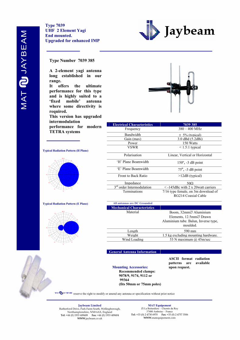
Type 7039
UHF 2 Element Yagi
End mounted.
Upgraded for enhanced IMP
Electrical Characteristics 7039 385
Frequency 380 – 400 MHz
Bandwidth 5% (typical)Gain (max) 3.0 dBd (5.2dBi)
Power 150 Watts VSWR < 1.5:1 typical
Polarisation Linear, Vertical or Horizontal
‘H’ Plane Beamwidth 150º, -3 dB point
‘E’ Plane Beamwidth 75º, -3 dB point
Front to Back Ratio >12dB (typical)
Impedance 503rd order Intermodulation < -145dBc with 2 x 20watt carriers
Terminations 7/16 type female, on 3m downlead of
RG214 Coaxial Cable
All antennas are DC Grounded
Mechanical Characteristics
Material Boom, 32mm Aluminium
Elements, 12.5mm Drawn
Aluminium tube. Balun, Inverse type,
moulded.
Length 590 mm
Weight 1.5 kg excluding mounting hardware.Wind Loading 53 N maximum @ 45m/sec
General Antenna Information
0dB / 90
60
30
0
30
60
90
120
150
180
150
120
-2 0
-1 3
-1 0
-6
-3
-1
Mounting Accessories:
Recommended clamps:
9078/9, 9174, 9112 or
99364
(fits 50mm or 75mm poles)
reserve the right to modify or amend any antenna or specification without prior notice
Typical Radiation Pattern (H Plane)
ASCII format radiation
patterns are available
upon request.
0dB / 90
60
30
0
30
60
90
120
150
180
150
120
-2 0
-1 3
-1 0
-6
-3
-1
Type Number 7039 385
A 2-element yagi antenna
long established in our
range.
It offers the ultimate
performance for this type
and is highly suited to a
‘fixed mobile’ antenna
where some directivity is
required.
This version has upgraded
intermodulation
performance for modern
TETRA systems

Jaybeam LimitedRutherford Drive, Park Farm South, Wellingborough,
Northamptonshire, NN8 6AX, EnglandTel: +44 (0) 1933 408408 Fax: +44 (0) 1933 408404
WWW jaybeam co uk
MAT EquipementZI La Boitardiere – Chemin du Roy
37400 Amboise - FranceTel: +33 (0) 2 4730 6970 Fax: +33 (0) 2 4757 3506
WWW.matequipement.com
Typical Radiation Pattern (H Plane)
Type 5043 00080o Sector TETRA 380-430MHz BandHigh Gain PanelDual Polarised
Type Number: 5043 000
A High Gain Dual Polarised (±± 45o) Panel, developed for UHF TETRAsystems.Latest construction technology gives the highest performance andexcellent reliability, together with an ascetic appearance.Strong mounting clamps are provided, allowing fitting to poles of up to115mm ∅∅.
Electrical Characteristics 5043 000Frequency 380 to 430 MHzGain (max) 14.0 dBi
Power 250 W per portVSWR < 1.3:1 full band
Polarisation ± 45ºHorizontal Beamwidth 80º ± 5º - 3 dB pointsElevation Beamwidth 19º ±1º - 3 dB points
Front to Back Ratio > 24 dB
Isolation between Ports > 30dB
3rd order Intermodulation -153dBc for 2 x 20watt carriers
Electrical Tilt 0ºImpedance 50 Ω
Terminations 2 x 7/16 DIN sockets on the bottomface
All antennas are DC Grounded
Mechanical CharacteristicsMaterial Housing: Aluminium, ‘Alocrom’ finish.
Shroud: Outdoor quality profiledextruded ‘Styrosun’
Dimensions 2000 x 400 x 195 mmWeight 17 kg approximate excluding mounting
hardware
Wind Loading 1000 N maximum @ 45m/secRv0403
General Antenna InformationShipping Dimensions 1 carton, 2250 x 600 x 315
0dB / 90
60
30
0
30
60
90
120
150
180
150
120
-2 0
-1 3
-1 0
-6
-3
-1
Mounting Accessories:Brackets supplied, fits pipes 48 to115 mm diameter. Provides 0º to± 10º mechanical tilt. Calibratedat 1º intervals.
reserve the right to modify or amend any antenna or specification without prior notice
Typical Radiation Pattern (E Plane)
ASCII format radiation patterns areavailable upon request.
0dB / 90
60
30
0
30
60
90
120
150
180
150
120
-2 0
-1 3
-1 0
-6
-3
-1

Jaybeam LimitedRutherford Drive, Park Farm South, Wellingborough,
Northamptonshire, NN8 6AX, EnglandTel: +44 (0) 1933 408408 Fax: +44 (0) 1933 408404
WWW jaybeam co uk
MAT EquipementZI La Boitardiere – Chemin du Roy
37400 Amboise - FranceTel: +33 (0) 2 4730 6970 Fax: +33 (0) 2 4757 3506
WWW.matequipement.com
Typical Radiation Pattern (H Plane)
Type 5043 01080o Sector TETRA 380-430MHz BandHigh Gain PanelDual Polarised 10o Electrical Downtilt
Type Number: 5043 010
A High Gain Dual Polarised (±± 45o) Panel, developed for UHF TETRAsystems.Latest construction technology gives the highest performance andexcellent reliability, together with an ascetic appearance.Strong mounting clamps are provided, allowing fitting to poles of up to115mm ∅∅.
Electrical Characteristics 5043 010Frequency 380 to 430 MHzGain (max) 14.0 dBi
Power 250 W per portVSWR < 1.3:1 full band
Polarisation ± 45ºHorizontal Beamwidth 80º ± 5º - 3 dB pointsElevation Beamwidth 19º ±1º - 3 dB points
Front to Back Ratio > 24 dB
Isolation between Ports > 30dB
3rd Order Intermodulation -153 dBc for 2 x 20watt carriers
Electrical Tilt 10ºImpedance 50 Ω
Terminations 2 x 7/16 DIN sockets on the bottomface.
All antennas are DC Grounded
Mechanical CharacteristicsMaterial Housing: Aluminium, ‘Alocrom’ finish.
Shroud: Outdoor quality profiledextruded ‘Styrosun’
Dimensions 2000 x 400 x 195 mmWeight 17 kg approximate excluding mounting
hardware
Wind Loading 1000 N maximum @ 45m/secRv0403
General Antenna InformationShipping Dimensions 1 carton, 2250 x 600 x 315
0dB / 90
60
30
0
30
60
90
120
150
180
150
120
-2 0
-1 3
-1 0
-6
-3
-1
Mounting Accessories:Brackets supplied, fits pipes 48 to115 mm diameter. Provides 0º to± 10º mechanical tilt. Calibratedat 1º intervals.
reserve the right to modify or amend any antenna or specification without prior notice
Typical Radiation Pattern (E Plane)
ASCII format radiation patterns areavailable upon request.
0dB / 90
60
30
0
30
60
90
120
150
180
150
120
-2 0
-1 3
-1 0
-6
-3
-1

Jaybeam LimitedRutherford Drive, Park Farm South, Wellingborough,
Northamptonshire, NN8 6AX, EnglandTel: +44 (0) 1933 408408 Fax: +44 (0) 1933 408404
WWW jaybeam co uk
MAT EquipementZI La Boitardiere – Chemin du Roy
37400 Amboise - FranceTel: +33 (0) 2 4730 6970 Fax: +33 (0) 2 4757 3506
WWW.matequipement.com
Typical Radiation Pattern (H Plane)
Type 5043 01580o Sector TETRA 380-430MHz BandHigh Gain PanelDual Polarised, 15o Electrical Downtilt
Type Number: 5043 015
A High Gain Dual Polarised (±± 45o) Panel, developed for UHF TETRAsystems.Latest construction technology gives the highest performance andexcellent reliability, together with an ascetic appearance.Strong mounting clamps are provided, allowing fitting to poles of up to115mm ∅∅.
Electrical Characteristics 5043 015Frequency 380 to 430 MHzGain (max) 13.5 dBi
Power 250 W per portVSWR < 1.3:1 full band
Polarisation ± 45ºHorizontal Beamwidth 80º ± 5º - 3 dB pointsElevation Beamwidth 20º ±1º - 3 dB points
Front to Back Ratio > 24 dB
Isolation between Ports > 30dB
3rd order Intermodulation -153 dBc for 2 x 20watt carriers
Electrical Tilt 15ºImpedance 50 Ω
Terminations 2 x 7/16 DIN sockets on the bottomface.
All antennas are DC Grounded
Mechanical CharacteristicsMaterial Housing: Aluminium, ‘Alocrom’ finish.
Shroud: Outdoor quality profiledextruded ‘Styrosun’
Dimensions 2000 x 400 x 195 mmWeight 17 kg approximate excluding mounting
hardware
Wind Loading 1000 N maximum @ 45m/secRv0403
General Antenna InformationShipping Dimensions 1 carton, 2250 x 600 x 315
0dB / 90
60
30
0
30
60
90
120
150
180
150
120
-2 0
-1 3
-1 0
-6
-3
-1
Mounting Accessories:Brackets supplied, fits pipes 48 to115 mm diameter. Provides 0º to± 10º mechanical tilt. Calibratedat 1º intervals.
reserve the right to modify or amend any antenna or specification without prior notice
Typical Radiation Pattern (E Plane)
ASCII format radiation patterns areavailable upon request.
0dB / 90
60
30
0
30
60
90
120
150
180
150
120
-2 0
-1 3
-1 0
-6
-3
-1

Jaybeam LimitedRutherford Drive, Park Farm South, Wellingborough,
Northamptonshire, NN8 6AX, EnglandTel: +44 (0) 1933 408408 Fax: +44 (0) 1933 408404
WWW jaybeam co uk
MAT EquipementZI La Boitardiere – Chemin du Roy
37400 Amboise - FranceTel: +33 (0) 2 4730 6970 Fax: +33 (0) 2 4757 3506
WWW.matequipement.com
Typical Radiation Pattern (H Plane)
Type 5023 01080o Sector TETRA 380-430MHz BandMedium Gain PanelDual Polarised 10o Electrical Downtilt
Type Number: 5023 010
A Medium Gain Dual Polarised (±± 45o) Panel, developed for UHFTETRA systems.Latest construction technology gives the highest performance andexcellent reliability, together with an ascetic appearance.Strong mounting clamps are provided, allowing fitting to poles of up to115mm ∅∅.
Electrical Characteristics 5023 010Frequency 380 to 430 MHzGain (max) 11.2 dBi
Power 200 W per portVSWR < 1.5:1 full band
Polarisation ± 45ºHorizontal Beamwidth 80º ± 5º - 3 dB pointsElevation Beamwidth 28º ±1º - 3 dB points
Front to Back Ratio > 24 dB
Isolation between Ports > 30dB
3rd Order Intermodulation -153dBc for 2 x 20watt carriers
Electrical Tilt 10º
Impedance 50 ΩTerminations 2 x 7/16 DIN sockets on the rear face,
facing downwards
All antennas are DC Grounded
Mechanical CharacteristicsMaterial Housing: Aluminium, ‘Alocrom’ finish.
Shroud: Outdoor quality profiledextruded ‘Styrosun’
Colour, Stone Grey : RAL 7030
Dimensions 1500 x 400 x 195 mmWeight 14 kg approximate excluding mounting
hardware
Wind Loading 810 N maximum @ 45m/secRv0403
General Antenna Informationk d i 1 1 0 600 31
0dB / 90
60
30
0
30
60
90
120
150
180
150
120
-2 0
-1 3
-1 0
-6
-3
-1
Mounting Accessories:Brackets supplied, fits pipes 48 to115 mm diameter. Provides 0º to± 10º mechanical tilt. Calibratedat 1º intervals.
reserve the right to modify or amend any antenna or specification without prior notice
Typical Radiation Pattern (E Plane)
ASCII format radiation patterns areavailable upon request.
0dB / 90
60
30
0
30
60
90
120
150
180
150
120
-2 0
-1 3
-1 0
-6
-3
-1

Jaybeam LimitedRutherford Drive, Park Farm South, Wellingborough,
Northamptonshire, NN8 6AX, EnglandTel: +44 (0) 1933 408408 Fax: +44 (0) 1933 408404
WWW jaybeam co uk
MAT EquipementZI La Boitardiere – Chemin du Roy
37400 Amboise - FranceTel: +33 (0) 2 4730 6970 Fax: +33 (0) 2 4757 3506
WWW.matequipement.com
Typical Radiation Pattern (H Plane)
Type 5023 01580o Sector TETRA 380-430MHz BandMedium Gain PanelDual Polarised 15o Electrical Downtilt
Type Number: 5023 015
A Medium Gain Dual Polarised (±± 45o) Panel, developed for UHFTETRA systems.Latest construction technology gives the highest performance andexcellent reliability, together with an ascetic appearance.Strong mounting clamps are provided, allowing fitting to poles of up to115mm ∅∅.
Electrical Characteristics 5023 015Frequency 380 to 430 MHzGain (max) 11.2 dBi
Power 200 W per portVSWR < 1.5:1 full band
Polarisation ± 45ºHorizontal Beamwidth 80º ± 5º - 3 dB pointsElevation Beamwidth 28º ±1º - 3 dB points
Front to Back Ratio > 24 dB
Isolation between Ports > 30dB
3rd Order Intermodulation -153dBc for 2 x 20watt carriers
Electrical Tilt 15º
Impedance 50 ΩTerminations 2 x 7/16 DIN sockets on the rear face,
facing downwards
All antennas are DC Grounded
Mechanical CharacteristicsMaterial Housing: Aluminium, ‘Alocrom’ finish.
Shroud: Outdoor quality profiledextruded ‘Styrosun’
Colour Stone Grey : RAL 7030
Dimensions 1500 x 400 x 195 mmWeight 14 kg approximate excluding mounting
hardware
Wind Loading 810 N maximum @ 45m/secRv0403
General Antenna Informationk d i 1 1 0 600 31
0dB / 90
60
30
0
30
60
90
120
150
180
150
120
-2 0
-1 3
-1 0
-6
-3
-1
Mounting Accessories:Brackets supplied, fits pipes 48 to115 mm diameter. Provides 0º to± 10º mechanical tilt. Calibratedat 1º intervals.
reserve the right to modify or amend any antenna or specification without prior notice
Typical Radiation Pattern (E Plane)
ASCII format radiation patterns areavailable upon request.
0dB / 90
60
30
0
30
60
90
120
150
180
150
120
-2 0
-1 3
-1 0
-6
-3
-1

Jaybeam LimitedRutherford Drive, Park Farm South, Wellingborough,
Northamptonshire, NN8 6AX, EnglandTel: +44 (0) 1933 408408 Fax: +44 (0) 1933 408404
WWW jaybeam co uk
MAT EquipementZI La Boitardiere – Chemin du Roy
37400 Amboise - FranceTel: +33 (0) 2 4730 6970 Fax: +33 (0) 2 4757 3506
WWW.matequipement.com
Typical Radiation Pattern (H Plane)
Type 5049 40090o Sector TETRA 380-430MHz BandHigh Gain PanelVertically Polarised
Type Number: 5049 400
A High Gain Linear Polarised Panel, developed for UHF TETRAsystems.Latest construction technology gives the highest performance andexcellent reliability, together with an ascetic appearance.Strong mounting clamps are provided, allowing fitting to poles of up to115mm ∅∅.
Electrical Characteristics 5049 400Frequency 380 to 430 MHzGain (max) 14.0 dBi
Power 250 WattsVSWR < 1.4:1 full band
Polarisation Linear, Vertical
Horizontal Beamwidth 92º ± 4º - 3 dB pointsElevation Beamwidth 19º ±1º - 3 dB points
Front to Back Ratio > 22 dB
3rd Order Intermodulation -153dBc for 2 x 20watt carriers
Electrical Tilt 0ºImpedance 50 Ω
Terminations 7/16 DIN socket on the lower face,facing downwards
All antennas are DC Grounded
Mechanical CharacteristicsMaterial Housing: Aluminium, ‘Alocrom’ finish.
Shroud: Outdoor quality profiledextruded ‘Styrosun’
Dimensions 2000 x 400 x 195 mm
Weight 17 kg approximate excluding mountinghardware
Wind Loading 1000 N maximum @ 45m/secRv0403
General Antenna InformationShipping Dimensions 1 carton, 2250 x 600 x 315
GW 29kg
0dB / 90
60
30
0
30
60
90
120
150
180
150
120
-2 0
-1 3
-1 0
-6
-3
-1
Mounting Accessories:Brackets supplied, fits pipes 48 to115 mm diameter. Provides 0º to± 10º mechanical tilt. Calibratedat 1º intervals.
Jaybeam reserve the right to modify or amend any antenna or specification without prior notice
Typical Radiation Pattern (E Plane)
ASCII format radiation patterns areavailable upon request.
0dB / 90
60
30
0
30
60
90
120
150
180
150
120
-2 0
-1 3
-1 0
-6
-3
-1
1Jaybeam Limited
Rutherford Drive, Park Farm South, Wellingborough,Northamptonshire, NN8 6AX, England
Tel: +44 (0) 1933 408408 Fax: +44 (0) 1933 408404WWW jaybeam co uk
MAT EquipementZI La Boitardiere – Chemin du Roy
37400 Amboise - FranceTel: +33 (0) 2 4730 6970 Fax: +33 (0) 2 4757 3506
WWW.matequipement.com
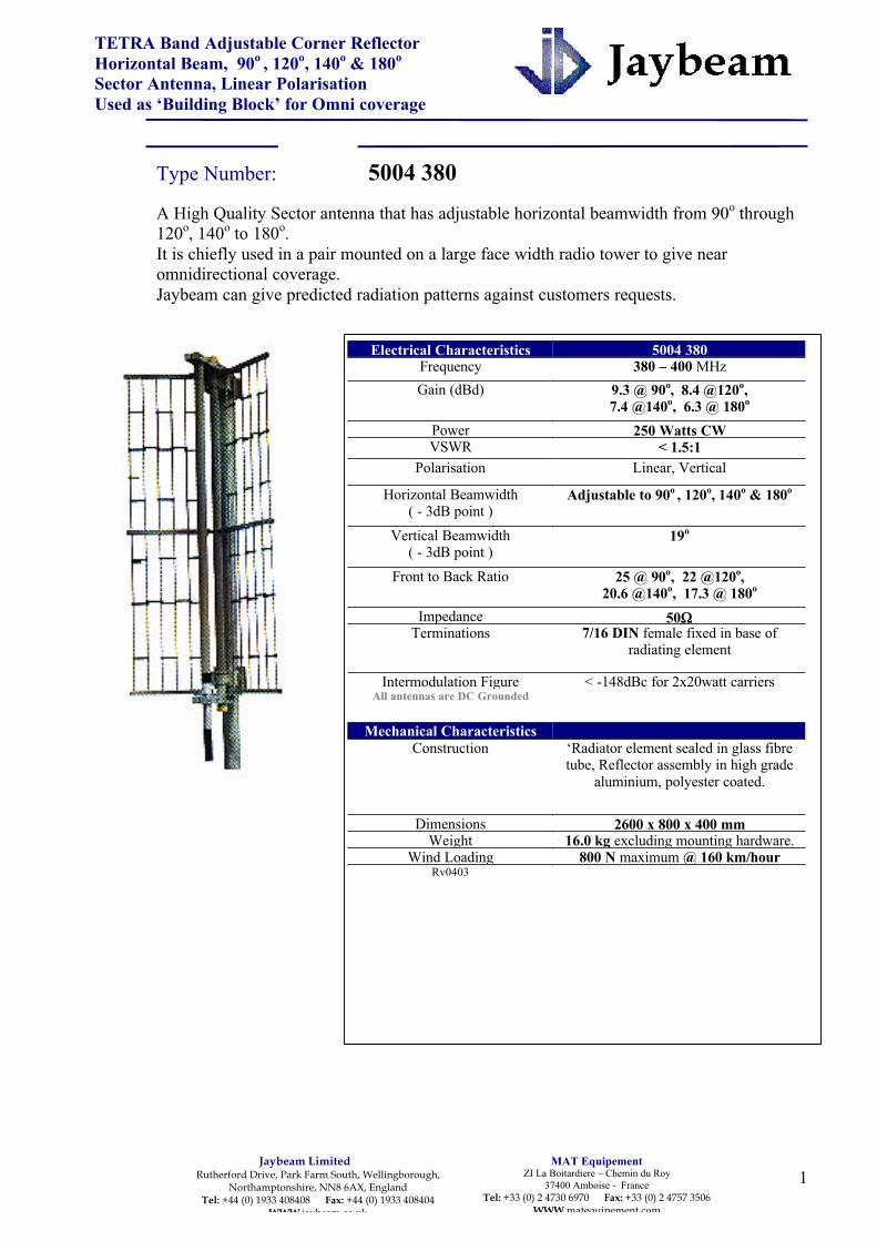
TETRA Band Adjustable Corner ReflectorHorizontal Beam, 90o , 120o, 140o & 180o
Sector Antenna, Linear PolarisationUsed as ‘Building Block’ for Omni coverage
Type Number: 5004 380A High Quality Sector antenna that has adjustable horizontal beamwidth from 90o through120o, 140o to 180o.It is chiefly used in a pair mounted on a large face width radio tower to give nearomnidirectional coverage.Jaybeam can give predicted radiation patterns against customers requests.
Electrical Characteristics 5004 380Frequency 380 – 400 MHzGain (dBd) 9.3 @ 90o, 8.4 @120o,
7.4 @140o, 6.3 @ 180o
Power 250 Watts CWVSWR < 1.5:1
Polarisation Linear, Vertical
Horizontal Beamwidth( - 3dB point )
Adjustable to 90o , 120o, 140o & 180o
Vertical Beamwidth( - 3dB point )
19o
Front to Back Ratio 25 @ 90o, 22 @120o,20.6 @140o, 17.3 @ 180o
Impedance 50ΩΩTerminations 7/16 DIN female fixed in base of
radiating element
Intermodulation Figure < -148dBc for 2x20watt carriersAll antennas are DC Grounded
Mechanical CharacteristicsConstruction ‘Radiator element sealed in glass fibre
tube, Reflector assembly in high gradealuminium, polyester coated.
Dimensions 2600 x 800 x 400 mmWeight 16.0 kg excluding mounting hardware.
Wind Loading 800 N maximum @ 160 km/hourRv0403

2Jaybeam Limited
Rutherford Drive, Park Farm South, Wellingborough,Northamptonshire, NN8 6AX, England
Tel: +44 (0) 1933 408408 Fax: +44 (0) 1933 408404WWW jaybeam co uk
MAT EquipementZI La Boitardiere – Chemin du Roy
37400 Amboise - FranceTel: +33 (0) 2 4730 6970 Fax: +33 (0) 2 4757 3506
WWW.matequipement.com
reserve the right to modify or amend any antenna or specification without prior notice
General Antenna InformationMounting details Optional steel brackets to fit pipes of 48-
115mm∅∅ and providing mechanical tilt up to15o at 1o intervals.
Weight of mounting brackets 8.1kg.
0dB / 90
60
30
0
30
60
90
120
150
180
150
120
-2 0
-1 3
-1 0
-6
-3
-1
Typical Radiation Pattern (E Plane) 2xAntennas 3.0m apart, 180o angle between.
0dB / 90
60
30
0
30
60
90
120
150
180
150
120 -5 dB
-10 dB
-20 dB
Typical Radiation Pattern (H Plane) 2xAntennas 3.0m apart, 180o angle between
0dB / 90
60
30
0
30
60
90
120
150
180
150
120
-2 0
-1 3
-1 0
-6
-3
-1
Typical Radiation Pattern (H Plane) 90o
0dB / 90
60
30
0
30
60
90
120
150
180
150
120
-2 0
-1 3
-1 0
-6
-3
-1
Typical Radiation Pattern (H Plane)140o
ASCII Format Radiation Patterns are availableupon request. CLICK HERE !Please contact Jaybeam Technical Sales

1Jaybeam Limited
Rutherford Drive, Park Farm South, Wellingborough, Northamptonshire, NN8 6AX, England
Tel: +44 (0) 1933 408408 Fax: +44 (0) 1933 408404 WWW.jaybeam.co.uk
MAT EquipementZI La Boitardiere – Chemin du Roy
37400 Amboise - France
Tel: +33 (0) 2 4730 6970 Fax: +33 (0) 2 4757 3506 WWW.matequipement.com
.
TETRA Band Adjustable Corner Reflector
Horizontal Beam, 90o, 120
o, 140
o & 180
o
Sector Antenna, Linear Polarisation 10oTilt
Used as ‘Building Block’ for Omni coverage
Type Number: 5004 390
A High Quality Sector antenna that has adjustable horizontal beamwidth from 90o through
120o, 140
o to 180
o.
It is chiefly used in a pair mounted on a large face width radio tower to give near
omnidirectional coverage.
Jaybeam can give predicted radiation patterns against customers requests.
Electrical Characteristics 5004 390
Frequency 380 – 400 MHz
Gain (dBd) 9.3 @ 90o, 8.4 @120
o,
7.4 @140o, 6.3 @ 180
o
Power 250 Watts CW
VSWR < 1.5:1
Polarisation Linear, Vertical
Horizontal Beamwidth
( - 3dB point ) Adjustable to 90
o, 120
o, 140
o & 180
o
Vertical Beamwidth
( - 3dB point ) 19o
Front to Back Ratio 25 @ 90o, 22 @120
o,
20.6 @140o, 17.3 @ 180
o
Electrical Beam Tilt 10o
Impedance 50Terminations 7/16 DIN female fixed in base of
radiating element
Intermodulation Figure < -148dBc for 2x20watt carriersAll antennas are DC Grounded
Mechanical Characteristics
Construction ‘Radiator element sealed in glass fibre
tube, Reflector assembly in high grade
aluminium, polyester coated.
Dimensions 2600 x 800 x 400 mm
Weight 16.0 kg excluding mounting hardware.Wind Loading 800 N maximum @ 160 km/hour
Rv0304

2Jaybeam Limited
Rutherford Drive, Park Farm South, Wellingborough, Northamptonshire, NN8 6AX, England
Tel: +44 (0) 1933 408408 Fax: +44 (0) 1933 408404 WWW.jaybeam.co.uk
MAT EquipementZI La Boitardiere – Chemin du Roy
37400 Amboise - France
Tel: +33 (0) 2 4730 6970 Fax: +33 (0) 2 4757 3506 WWW.matequipement.com
reserve the right to modify or amend any antenna or specification without prior notice
General Antenna Information
Mounting details Optional steel brackets to fit pipes of 48-
115mm and providing mechanical tilt up to
15o at 1o intervals.
Weight of mounting brackets 8.1kg.
0dB / 90
60
30
0
30
60
90
120
150
180
150
120
-2 0
-1 3
-1 0
-6
-3
-1
Typical Radiation Pattern (E Plane) 140deg
0dB / 90
60
30
0
30
60
90
120
150
180
150
120
-2 0
-1 3
-1 0
-6
-3
-1
Typical Radiation Pattern (E Plane) 90deg
0dB / 90
60
30
0
30
60
90
120
150
180
150
120
-2 0
-1 3
-1 0
-6
-3
-1
Typical Radiation Pattern (H Plane) 90o
0dB / 90
60
30
0
30
60
90
120
150
180
150
120
-2 0
-1 3
-1 0
-6
-3
-1
Typical Radiation Pattern (H Plane)
140o
ASCII Format Radiation Patterns are available
upon request.
Please contact Jaybeam Technical Sales

Jaybeam LimitedRutherford Drive, Park Farm South, Wellingborough,
Northamptonshire, NN8 6AX, EnglandTel: +44 (0) 1933 408408 Fax: +44 (0) 1933 408404
WWW jaybeam co uk
MAT Equipement17 bis, rue du Chemin Vert, 94100
Saint Maur Des Fosses, Paris, FranceTel: +33 (0) 1 55961010 Fax: +33 (0) 1 55960100
WWW.matequipement.com
Typical Radiation Pattern (H Plane)
Type 5047 000TETRA Band Microcell AntennaIndoor (Fire Retardant) & OutdoorWall Mounted
Type Number: 5047 000
A useful Microcell antenna for the UHF TETRA Band. (380-400MHz)Designed for wall mounting it can be used indoors (LS0H materials) oroutdoors. (IP66)
Only high quality components are used to give optimum performance,particularly regarding intermodulation, for such a compact antenna
Electrical Characteristics 5047 000Frequency 380 – 400 MHz
Gain 4.5 dBi (on typical wall surface)Power 50 WVSWR < 1.5:1
Polarisation Vertical
Horizontal Beamwidth Typically 106º, -3 dB pointsFront to Back Ratio >10 dB
Elevation Beamwidth Typically 112º, -3 dB points
Lightning Protection Direct ground all conductivecomponents
Impedance 50ΩIntermodulation 3rd order – minimum –100dBm with 2 x
5 watt carriers.Terminations 500 mm RG303 cable, FEP outer
jacket, PTFE dielectric, terminated in ‘N’ socket
Cable can be routed downwards,backwards or upwards
All antennas are DC Grounded
Mechanical CharacteristicsMaterial Aluminium housing, Alocrom finish,
Stainless steel mounting plate. Shroud, UV Resistant, Halogen free
FR ABS Colour WhiteUL94V-O, CAA No.8 Sec 2.2b
FAR 25.853bDimensions 305 x 225 x 60 mm
Weight 1.05 kgWind Loading 85 N maximum @ 160 km/hour
0dB / 90
60
30
0
30
60
90
120
150
180
150
120
-2 0
-1 3
-1 0
-6
-3
-1
Mounting Arrangement:Stainless Steel back plate is fixed to wall via 4 screwholes.Antenna is then clipped onto the backplate giving a secureand unobtrusive mounting.
JAYBEAM reserve the right to modify or amend any antenna or specification without prior notice
Typical Radiation Pattern (E Plane)
ASCII format radiationpatterns are available uponrequest.
0dB / 90
60
30
0
30
60
90
120
150
180
150
120
-2 0
-1 3
-1 0
-6
-3
-1

OMNIDIRECTIONAL ANTENNA
380 - 400 MHz
MAT Equipement - ZI La Boitardière - Chemin du Roy - 37400 Amboise - France - Tel. : 33 (0)2 47 30 69 70
DT
52
58
- E
d A
an
gla
is -
pa
ge
1/1
-
We
rese
rve
the
right
to m
odify
our p
rodu
cts
with
out p
rior n
otic
e.
MA521P00 is a shrouded low profile omnidirectional antenna intended for
indoor coverage by ceiling installation. It is fitted with a 0.5 meter coaxial
cable and a N female connector
TECHNICAL DATA :
Product code MA521P00
Frequency range 380 to 400 MHz
Nominal impedance 50 ohms
VSWR 2
Polarisation linear, vertical
Gain 0 dBi (at connector level))
Radiation in horizontal plane omnidirectional within 0.5 dB
Radiation in vertical plane beamwidth (E plane) at 3 dB : 80°
Maximum power 3 watts
Connection at the back of the antenna, by a 0.5 meter
RG58 black coaxial cable with N female
connector at the end
Dimension height : 70 mm
diameter: 204 mm
Weight 470 g
Materials / colours shroud : white plastic
back plate : aluminium, natural
Grounding All the metallic parts of the antenna are DC connected
to the connector ground, including the inner conductor
of the connector and the back plate.
Installation By three holes with the screws and wall plugs supplied
with the antenna. Three white caps are supplied to
hide the screws after installation.
Note : Metal in the ceiling structure affects the antenna. On a fully metallic
ceiling, maximum VSWR is 2.3 and radiation is totally downwards.
Typical radiation in horizontal plane :0 dB
-1
-3
-6
-10
-13
-20
0°
30°
60°
60°
30°
Typical radiation in vertical plane : (in free space antenna facing downwards
or on non metallic ceiling) 0 dB
-1
-3
-6
-10
-13
-20
0°
30°
60°
60°
30°
MA521P00
JAYBEAM - Rutherford drive - Park Farm South - Wellingborough - Northants - NN8 6AX - UK - Tel : +44 (0) 1933 408408

Jaybeam LimitedRutherford Drive, Park Farm South, Wellingborough,
Northamptonshire, NN8 6AX, EnglandTel: +44 (0) 1933 408408 Fax: +44 (0) 1933 408404
WWW.jaybeam.co.uk
MAT EquipementZI La Boitardiere – Chemin du Roy
37400 Amboise - FranceTel: +33 (0) 2 4730 6970 Fax: +33 (0) 2 4757 3506
WWW.matequipement.com
‘Norstel’ type clampsAll made from galvanised drop forged steel.
Made to fit Scaffold poles (48.4mm∅), use inconjunction with increasing sleeves (below) tofit antenna booms.9078Fixed 90o double coupler.
90751/2 Norstel, c/w bolt for fixing through a
plate.9077Swivelling double coupler. (please note,cannot be locked into position)
Increasing sleevesTo fit antenna booms and enable clamping
with norstel clamps (above).9174fits 1” (25.4mm) ∅ booms
9079Fits 1 ¼ ” (32mm)∅
(our most popular size)9719Fits 1 ½”(38mm)∅
9894(was JBL73)
Good strong clampFits 1 ¼” booms to upTo 2” (50mm) poles
9112Standard cross over plateWill fit 32 & 38mmantenna booms to 50 &60mm poles.(confirm sizes whenordering)
9016Medium duty,
Fits 1 ¼” (32mm) boomsto up to 2” (50mm)
Poles.
9891(was JBL63)
Medium-light duty fits25mm-50mm sizes both
ways and can be used as aparallel clamp as well.
ANTENNA MOUNTINGHARDWARE

Jaybeam LimitedRutherford Drive, Park Farm South, Wellingborough,
Northamptonshire, NN8 6AX, EnglandTel: +44 (0) 1933 408408 Fax: +44 (0) 1933 408404
WWW.jaybeam.co.uk
MAT EquipementZI La Boitardiere – Chemin du Roy
37400 Amboise - FranceTel: +33 (0) 2 4730 6970 Fax: +33 (0) 2 4757 3506
WWW.matequipement.com
99364Circular cast alloy clamp,
gives good two pointfixing.
Supplied with 2x50mmSS ‘U’ bolts and
‘1/2’moon castings to fitantenna booms of 25mm
to 50mm∅Order either 50mm or
75mm U bolts separatelyto fit poles.
99366
Strong square cast alloyclamp,
Fits up to 50mm pipes asa crossover or parallel
clamp.Supplied with U bolts.
99284Rectangular cast alloyclamp, gives good two
point fixing.Supplied with 2x50mm
SS ‘U’ bolts and‘1/2’moon castings to fitantenna booms of 25mm
to 50mm∅Order either
50/75/100/125mm U boltsseparately to fit poles.
99365Rectangular cast alloyclamp similar to 99284
but with facility fortilting, ( ± 5 o ) to allow
for rake of a tower.
Order either50/75/100mm U boltsseparately to fit poles
99285Heavy Duty cast alloycrossover clamp, will
accommodate tube sizesup to 115mm ∅
9864Originally designed forour range of colinear
antennas this clamp fits 1 ¼” (32mm) verticallyto poles or rails of up to
2” (50mm)
Parallel Clamps
9099Galvanised steel throughout, fits pipes from 32mm to60mm ∅.
99235Similar to 9099 but fits pipes from 48mm to 76mm∅.
ANTENNA MOUNTINGHARDWARE
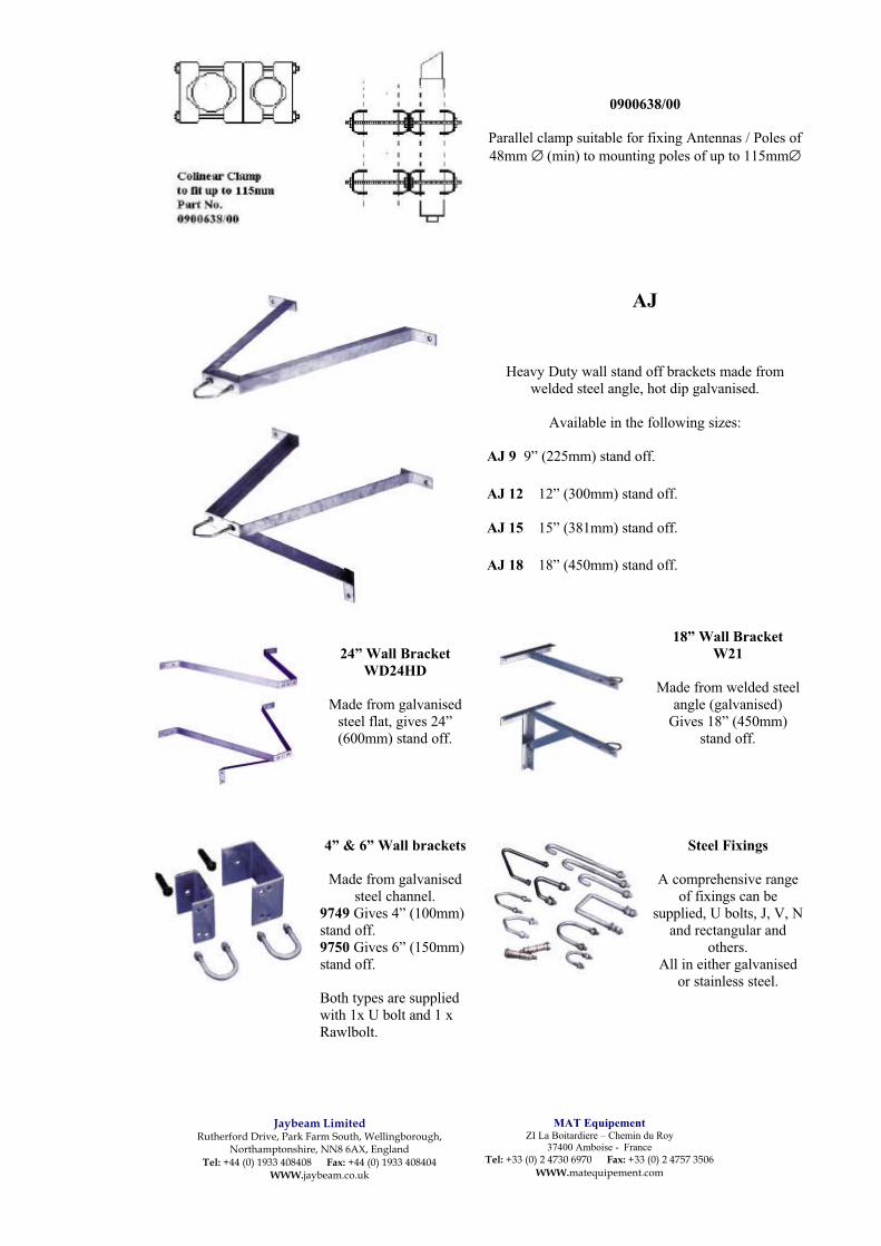
Jaybeam LimitedRutherford Drive, Park Farm South, Wellingborough,
Northamptonshire, NN8 6AX, EnglandTel: +44 (0) 1933 408408 Fax: +44 (0) 1933 408404
WWW.jaybeam.co.uk
MAT EquipementZI La Boitardiere – Chemin du Roy
37400 Amboise - FranceTel: +33 (0) 2 4730 6970 Fax: +33 (0) 2 4757 3506
WWW.matequipement.com
0900638/00
Parallel clamp suitable for fixing Antennas / Poles of48mm ∅ (min) to mounting poles of up to 115mm∅
AJ
Heavy Duty wall stand off brackets made fromwelded steel angle, hot dip galvanised.
Available in the following sizes:
AJ 9 9” (225mm) stand off.
AJ 12 12” (300mm) stand off.
AJ 15 15” (381mm) stand off.
AJ 18 18” (450mm) stand off.
24” Wall BracketWD24HD
Made from galvanisedsteel flat, gives 24”(600mm) stand off.
18” Wall BracketW21
Made from welded steelangle (galvanised)
Gives 18” (450mm)stand off.
4” & 6” Wall brackets
Made from galvanisedsteel channel.
9749 Gives 4” (100mm)stand off.9750 Gives 6” (150mm)stand off.
Both types are suppliedwith 1x U bolt and 1 xRawlbolt.
Steel Fixings
A comprehensive rangeof fixings can be
supplied, U bolts, J, V, Nand rectangular and
others.All in either galvanised
or stainless steel.

Jaybeam LimitedRutherford Drive, Park Farm South, Wellingborough,
Northamptonshire, NN8 6AX, EnglandTel: +44 (0) 1933 408408 Fax: +44 (0) 1933 408404
WWW.jaybeam.co.uk
MAT EquipementZI La Boitardiere – Chemin du Roy
37400 Amboise - FranceTel: +33 (0) 2 4730 6970 Fax: +33 (0) 2 4757 3506
WWW.matequipement.com
Universal tower cleats9110Supplied with 1 U bolt9476Double U bolts
944348.5mm ∅ Stub welded
NB‘J’ bolts need to be ordered separately
J6 6” (150mm) J bolt fits angle of 50-90mmJ8 8” (200mm) J bolt fits angle of 60-130mmJ10 10” (250mm) J bolt fits angle of 90-180mm
Cable and Connectors
A comprehensive range of Low Lossfeeder cable** and accessories are
available.
Connectors, grounding kits, fixingclamps etc.
All of high quality at competitive prices.
** See separate catalogue for ‘Hyperflex’range.
Recommended