Test Equipment Solutions Datasheet
Test Equipment Solutions Ltd specialise in the second user sale, rental and distribution of quality test & measurement (T&M) equipment. We stock all major equipment types such as spectrum analyzers, signal generators, oscilloscopes, power meters, logic analysers etc from all the major suppliers such as Agilent, Tektronix, Anritsu and Rohde & Schwarz.
We are focused at the professional end of the marketplace, primarily working with customers for whom high performance, quality and service are key, whilst realising the cost savings that second user equipment offers. As such, we fully test & refurbish equipment in our in-house, traceable Lab. Items are supplied with manuals, accessories and typically a full no-quibble 2 year warranty. Our staff have extensive backgrounds in T&M, totalling over 150 years of combined experience, which enables us to deliver industry-leading service and support. We endeavour to be customer focused in every way right down to the detail, such as offering free delivery on sales, covering the cost of warranty returns BOTH ways (plus supplying a loan unit, if available) and supplying a free business tool with every order.
As well as the headline benefit of cost saving, second user offers shorter lead times, higher reliability and multivendor solutions. Rental, of course, is ideal for shorter term needs and offers fast delivery, flexibility, try-before-you-buy, zero capital expenditure, lower risk and off balance sheet accounting. Both second user and rental improve the key business measure of Return On Capital Employed.
We are based near Heathrow Airport in the UK from where we supply test equipment worldwide. Our facility incorporates Sales, Support, Admin, Logistics and our own in-house Lab.
All products supplied by Test Equipment Solutions include:
- No-quibble parts & labour warranty (we provide transport for UK mainland addresses).- Free loan equipment during warranty repair, if available.- Full electrical, mechanical and safety refurbishment in our in-house Lab.- Certificate of Conformance (calibration available on request).- Manuals and accessories required for normal operation.- Free insured delivery to your UK mainland address (sales).- Support from our team of seasoned Test & Measurement engineers.- ISO9001 quality assurance.
Test equipment Solutions LtdUnit 8 Elder WayWaterside DriveLangleyBerkshireSL3 6EP
T: +44 (0)1753 596000F: +44 (0)1753 596001
Email: [email protected]: www.TestEquipmentHQ.com
Testing for Optimal Results
Unmatched Value
ATS-2Audio Test and Measurement System
Turn on ATS-2: Audio Testing to Meet Your Deadline and Budget
Audio Precision’s PC-controlled ATS-2 audio test and measurement system provides
design engineers and technicians with Audio Precision quality and the ability to choose
performance capabilities to match specific needs and budgets. By quickly discovering
and isolating circuit problems with its Harmonic Distortion Analyzer, ATS-2 can
dramatically decrease your time to market. With its Multitone Analyzer, ATS-2 provides
comprehensive solutions to your audio testing challenges by executing five performance
tests in a single acquisition, collating all the data you need to graph any test
result—all in less than one second. And because it’s PC-controlled, ATS-2 allows you to
leverage your existing PC investment.
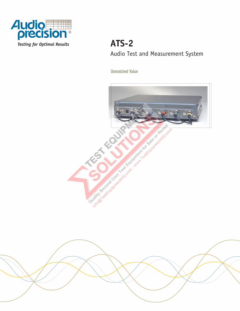
Multitone Performance Tests
• 2-Channel Frequency Response
• Noise versus Frequency
• Total Distortion versus Frequency
• Interchannel Separation versus Frequency
• Interchannel Phase Response
Multitone test signal from Generator with flatspectrum and virtually no distortion and noise.Note some frequencies in the higher area of thespectrum are different on each channel to allowfor crosstalk measurements.
Multitone signal received from the device undertest. Note the amplitude of the fundamentals isrepresenting the response of the device and thehigher signals near the bottom of the spectrumrepresent noise and distortion.
The interface measurement capability in ATS-2 determines whether or not the signal
from a digital device meets standards and is compatible with other devices. High
performance measurement capabilities include jitter and FFT of jitter, pulse
amplitude, word width, bit activity, sample rate and high-level decoded status bits.
Interface stimulus features simulate real-world degradations to measure the effect on
the device during testing.
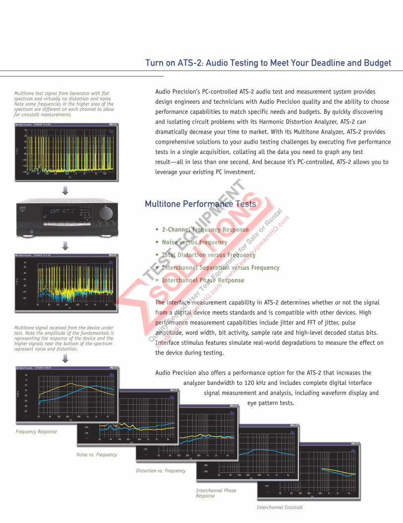
Audio Precision also offers a performance option for the ATS-2 that increases the
analyzer bandwidth to 120 kHz and includes complete digital interface
signal measurement and analysis, including waveform display and
eye pattern tests.
Frequency Response
Noise vs. Frequency
Distortion vs. Frequency
Interchannel PhaseResponse
Interchannel Crosstalk
High Performance, Simplified
ATS-2 offers dual analyzers to quickly
identify and repair the problems that occur
during the design and manufacture of
audio equipment. The Harmonic Distortion
Analyzer provides insight into a variety of
circuit malfunctions, allowing an engineer
or technician to isolate circuit problems
and fix them quickly. The Multitone
Analyzer—an FFT analyzer coupled with an
arbitrary waveform generator—performs a
variety of performance tests quickly.
Without multitone, those tests must be set
up and executed one at a time.
With PC-controlled functionality, ATS-2
allows you to leverage your existing PC
investment and gives you a familiar
interface to:
• Monitor instruments
• Graphically display test data
• Manage files for test setups
• Easily share and archive data
• Generate reports with your preferredword processing application; and
• Export test data to analysisprograms—such as MATLAB®—forextended analysis.
Reach Your Market Faster
The rapid, single acquisition testing of
ATS-2’s Multitone Analyzer saves you
the time and expense of individually
setting up and executing each test. It
eliminates errors by providing a
comprehensive set of answers to your
performance questions with one easy
setup. By decreasing the time spent on
finding and fixing circuit problems,
ATS-2 decreases your time to market.
High Performance,Unmatched Value
The ATS-2 provides design engineers and
technicians with Audio Precision quality
and the ability to choose performance
capabilities to match specific needs and
budgets. By getting you to market faster
through a dramatically faster testing
process, ATS-2 allows for a quicker return
on investment on your developments.
And by leveraging your existing PCs,
ATS-2 increases your asset utilization,
helping to improve your design’s
financial performance. And the inherent
high-reliability of the ATS-2 is backed up
by a three-year warranty, the best in the
industry.
Digital interface signal analysis—EyePattern test.The PC-controlled ATS-2 lets you enjoy the
longevity of Audio Precision test and
measurement equipment without sacrificing
the regular performance upgrades available
with your PC platform.
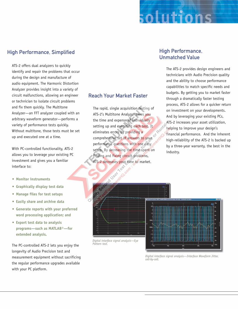
Digital interface signal analysis—Interface Waveform Jitter,cell-by-cell.
ATS-2 sets a new mark in value for
computer-controlled audio testing
systems. ATS-2 puts a broad set of
capabilities, high measurement
performance and a proud legacy of
excellence into a light-weight, compact
and affordable general purpose instrument
suited to the design lab, broadcast facility
or production line.
Key ATS-2 features
• Analog and digital inputs andoutputs.
• Generation of test signals for bothanalog and digital devices.
• Multi-functioned audio analysis,spectrum analysis, multitoneanalysis, detailed harmonic analysis,optional interface analysis.
• Full complement of graphing andreport options.
Turn on ATS-2: Audio Testing to Meet Your Challenges
High Performance, by Design
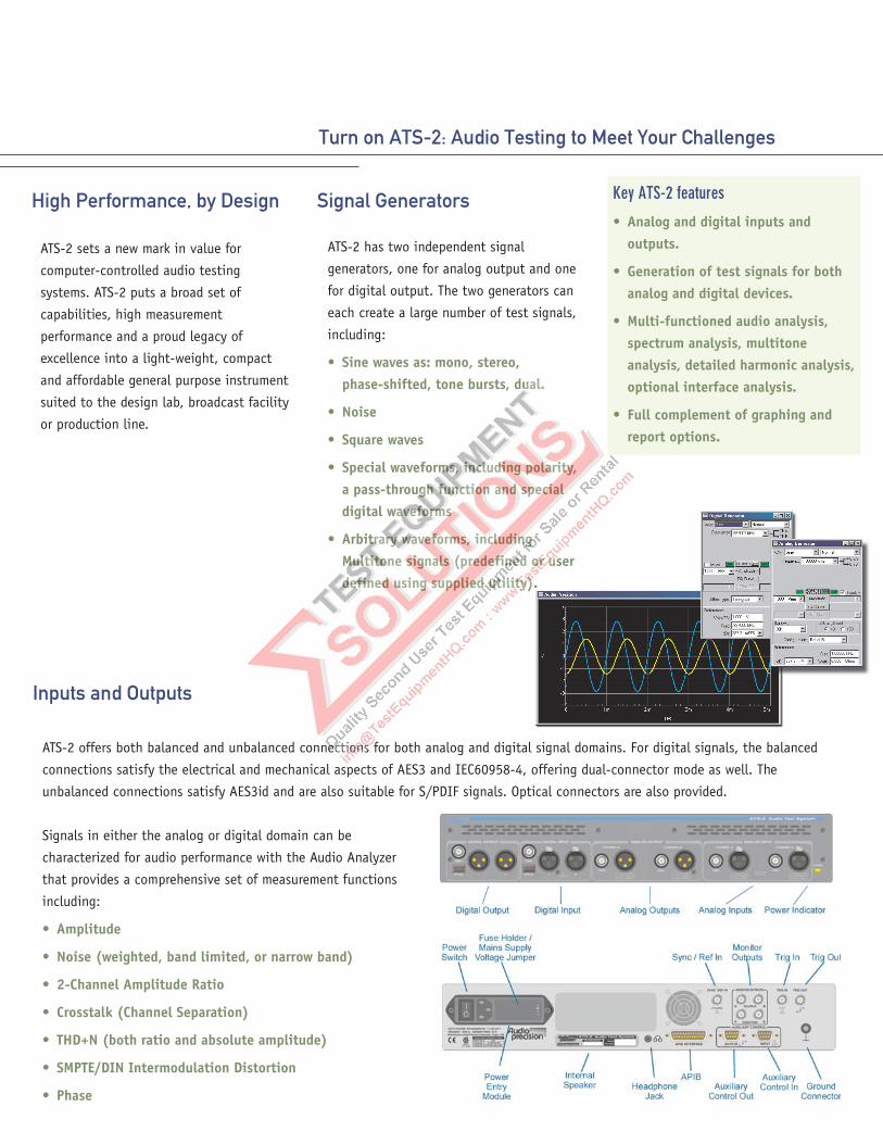
Inputs and Outputs
ATS-2 offers both balanced and unbalanced connections for both analog and digital signal domains. For digital signals, the balanced
connections satisfy the electrical and mechanical aspects of AES3 and IEC60958-4, offering dual-connector mode as well. The
unbalanced connections satisfy AES3id and are also suitable for S/PDIF signals. Optical connectors are also provided.
Signals in either the analog or digital domain can be
characterized for audio performance with the Audio Analyzer
that provides a comprehensive set of measurement functions
including:
• Amplitude
• Noise (weighted, band limited, or narrow band)
• 2-Channel Amplitude Ratio
• Crosstalk (Channel Separation)
• THD+N (both ratio and absolute amplitude)
• SMPTE/DIN Intermodulation Distortion
• Phase
Signal Generators
ATS-2 has two independent signal
generators, one for analog output and one
for digital output. The two generators can
each create a large number of test signals,
including:
• Sine waves as: mono, stereo,phase-shifted, tone bursts, dual.
• Noise
• Square waves
• Special waveforms, including polarity,a pass-through function and specialdigital waveforms
• Arbitrary waveforms, includingMultitone signals (predefined or userdefined using supplied utility).
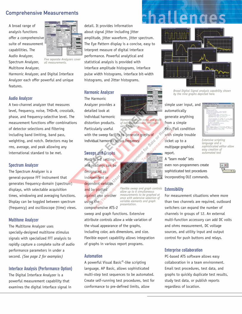
A broad range of
analysis functions
offer a comprehensive
suite of measurement
capabilities. The
Audio Analyzer,
Spectrum Analyzer,
Multitone Analyzer,
Harmonic Analyzer, and Digital Interface
Analyzer each offer powerful and unique
features.
Audio AnalyzerA two-channel analyzer that measures
level, frequency, noise, THD+N, crosstalk,
phase, and frequency-selective level. The
measurement functions offer combinations
of detector selections and filtering
including band limiting, band pass,
weighting, and notch. Detectors may be
rms, average, and peak allowing any
international standard to be met.
Spectrum AnalyzerThe Spectrum Analyzer is a
general-purpose FFT instrument that
generates frequency-domain (spectrum)
displays, with selectable acquisition
times, windowing and averaging functions.
Display can be toggled between spectrum
(frequency) and oscilloscope (time) views.
Multitone AnalyzerThe Multitone Analyzer uses
specially-designed multitone stimulus
signals with specialized FFT analysis to
rapidly capture a complete suite of audio
performance parameters in under a
second. (See page 2 for examples)
Interface AnalysisThe Digital Interface Analyzer is a
powerful measurement capability that
examines the digital interface signal in
Comprehensive Measurements
simple user input, and
automatically
generate anything
from a simple
Pass/Fail condition
with simple trouble
ticket up to a
multipage graphical
report.
A “learn mode” lets
even non-programmers create
sophisticated test procedures
incorporating OLE commands.
ExtensibilityFor measurement situations where more
than two channels are required, outboard
switchers can expand the number of
channels in groups of 12. An external
multi-function accessory can add DC volts
and ohms measurement, DC voltage
sources, and utility input and output
control for push buttons and relays.
Enterprise collaborationPC-based ATS software allows easy
collaboration in a team environment.
Email test procedures, test data, and
graphs to quickly duplicate test results,
study test data, or publish reports
regardless of location.
detail. It provides information
about signal jitter including jitter
amplitude, jitter waveform, jitter spectrum.
The Eye Pattern display is a concise, easy to
interpret measure of digital interface
performance. Powerful analytical and
statistical analysis is provided with
interface amplitude histograms, interface
pulse width histograms, interface bit-width
histograms, and Jitter histograms.
Harmonic AnalyzerThe Harmonic
Analyzer provides a
detailed look at
individual harmonic
distortion products.
Particularly useful
with the sweep facility to generate graphs of
individual harmonics versus frequency.
Sweeps and GraphsMost ATS-2 settings
and readings can be
designated as
independent or
dependent variables
and be plotted
against one another
using the
comprehensive ATS-2
sweep and graph functions. Extensive
attribute controls allow a wide variation of
the visual appearance of the graphs,
including color, axis dimensions, and size.
Flexible export capability allows integration
of graphs in various report programs.
AutomationA powerful Visual Basic�-like scripting
language, AP Basic, allows sophisticated
multi-step test sequences to be automated.
Create self-running test procedures, test for
conformance to pre-defined limits, allow
Flexible sweep and graph controlsallow up to 6 simultaneousmeasurements to be graphed atonce with extensive selection ofvariable elements and graphpresentation.
Five separate Analyzers coverall measurements.
Extensive scriptinglanguage and asophisticated editor alloweasy creation ofautomated test
Broad Digital Signal analysis capability shownby the nine graphs depicted here.
Harmonic Analyzer panel and graphof individual harmonic amplitudeversus frequency.
SIGNAL GENERATOR OUTPUTS
Waveforms Analog Digital
Sine Family (Normal, Var Phase, Stereo,Dual, Shaped Burst, EQ), IMD(SMPTE/DIN 4:1, 1:1) Square, Noise,Arbitrary Waveform (Multitone), Special(Polarity, Pass Thru)
Sine Family (Normal, Var Phase,Stereo, Dual, Shaped Burst, EQ,Burst, Offset) IMD (SMPTE/DIN4:1, 1:1) Square, Noise,Arbitrary Waveform (Multitone),Special (Polarity, Pass Thru,Monotonicity, J-Test, WalkingOnes, Walking Zeros, ConstantValue, Random)
Frequency Range 2 Hz to 61.6 kHz 2 Hz to .50 x SR (Sample Rate)Frequency Accuracy ±0.0002%Frequency Resolution SR/2^23Amplitude Range
Balanced <250 �Vrms to 16.00 Vrms [+26.3 dBu]Unbalanced <250 �Vrms to 8.00 Vrms [+20.28 dBu]
Amplitude Accuracy ±0.09dB [±1.0%]Amplitude Resolution 0.007 dB or 0.60 �Vrms, whichever is
largerSR/2^23
Flatness±0.01 dB (20 Hz-20 kHz, 500 Hz ref) ±0.001 dB
THD+N1 0.000001% [-160 dB]20 Hz-20 kHz �(0.0009% [-101 dB] + 1.6 �V)
Frequency Range 10 Hz–20 kHz 2 Hz to SR / 6, in even integersub-multiples of SR
Risetime Typically 2.0 �s N/A
LF Tone Range 40 Hz to 500 Hz 40 Hz to 500 HzHF Tone Range 2 kHz to 60 kHz 2 kHz to 0.47 x SRMix Ratio 4:1 or 1:1(LF:HF) 4:1 or 1:1(LF:HF)Residual IMD2 �0.0025% [-92 dB]
Length 256 to 16384 points per channel 256 to 16384 points perchannel
Frequency Range DC to 0.47 x SR DC to 0.47 x SRFrequency Resolution SR / Length SR / Length
White, Pseudo-Random, RectangularPDF, 30 kHz or 60 kHz BW
White, Pseudo-Random White,Rectangular PDF, Bandwidth0.50 x SR
Burst Shaped burst: Raised cosine Shaped burst: Rectangularenvelope, raised cosine
Source Configuration Balanced (XLR), Unbalanced (XLR andBNC), or Common Mode Test (XLR)
Source Impedances (Rs)Balanced or CommonMode Test
Nominally 40� or 150� (200� withoption EURZ)
Unbalanced Nominally 20� or 50�
Output Current Limit Typically 50 mAMax Output Power into 600�
Balanced +24.1 dBm (Rs = 40�)Unbalanced +18.4 dBm (Rs = 20�)
Output Related Crosstalk(20Hz- 20kHz)
�(-100 dB + 3 �V)
FormatsBalanced (XLR) AES3 per AES3-1997Unbalanced (BNC) SPDIF-EIAJ per IEC 60958Optical (Toslink�) Per IEC 60958-3
Sample Rate Range 28.8 kHz to 108 kHz perconnector
Word Width 8 to 24 bitsOutput Amplitude
Balanced into 110� Range 0 to 5.10 VppUnbalanced into 75� Range 0 to 1.275 VppOptical (Toslink�) Nominal intensity, not variable
ANALYZER
Audio Analyzer
Resolution 24-bit sigma-delta 8-24 bitsw/Performance Option 16-bit sigma-delta
Sample Rate 28.8ks/s to 108ks/s variable; or65.536ks/s fixed
28.8kHz to 100kHz AES/EBU;64kHz-200kHz Dual ConnectorAES/EBU
w/Performance Option 56ks/s to 215ks/s variable; or131.072ks/s or 262.144 ks/s fixed
Input Ranges 355 mVp to 200 Vp in 6.02 dB stepsMaximum Rated Input 200Vp, 140Vrms (dc to 20kHz);
overload protected in all rangesInput Impedance
Balanced Nominally 200 k�
Unbalanced Nominally 100 k�
CMRR3
355mVp to 5.6Vp range �80 dB, 10 Hz–20 kHz11.2 Vp to 200Vp range �50 dB, 10 Hz–1 kHz
Input Related Crosstalk �(-100 dB +3 �V), at 20 kHzFormats
Balanced (XLR) AES/EBU (per AES 3-1997);SPDIF-EIAJ; Optical
Unbalanced (BNC) SPDIF-EIAJ per IEC 60958Optical (Toslink�) Per IEC 60958-3
Sample Rates 28.8 kHz to 108 kHz perconnector
Word Width 8 to 24 bits
Measurement Range <1 �V-140 Vrms [-118 dBu to + 45.1dBu]
-120 dBFS to 0 dBFS (usable to-140 dBFS)
Accuracy (1 kHz) ±0.09 dB [±1.0%] ±0.002 dB [±0.023%]Flatness4
“HiRes” A/D ±0.01 dB, 20 Hz to 20 kHz ±0.002 dB, 10 Hz to 0.45xSR“HiBW”5 A/D ±0.01dB, 20 Hz to 20 kHz;
±0.1 dB, 20k to 120 kHzDetection RMS, FAST RMS, or QPK per IEC 468
(CCIR)SAME
Range > 10 Hz to 30 kHz (SR = 65.536 kS/s) < 10 Hz to 0.47xSRWith Performance Option > 10 Hz to 120 kHz
Accuracy ±0.0002% [2 PPM] SAMEResolution 0.00001% of SR [0.007 Hz at 65.536
kS/s]SAME
Phase Measurement Analog Digital
Measurement Ranges 180, -90 to +270, or 0 to +360 deg SAMEAccuracy 2 deg, 10 Hz to 0.45xSR
10 Hz to 5 kHz 2 deg5 kHz to 20 kHz 3 deg20 kHz to 50 kHz (WithPerformance Option)
4 deg
Resolution 0.01 deg SAME
A-weighted � 1.2 �V rms � -142 dBFSDolby 2K � 2.0 �V rms � -134 dBFSIEC 468 (CCIR) � 5.0 �V rms � -127 dBFS20 kHz LP � 1.6 �V rms � -140 dBFS
Fundamental Range 10 Hz to 0.47xSR SAMEMeasurement Range 0 to 100% SAMEAccuracy ±0.3 dB, 10 Hz to 0.45xSR
(no filters selected)SAME
Residual THD+N � 0.0009% [-101 dB] + 1.6 �V (with20 kHz LP)
1-System specification including contributions from both generator and analyzer, 20 kHz measurement bandwidth.2-System specification with 60 Hz/7 kHz or 250 Hz/8 kHz test signal combinations and Vin � 200 mV.3-CMRR performance below 50 Hz degrades with AC coupling.4-1 kHz ref. Flatness derates above 5 kHz by an additional ±0.02 dB in the 22.4 V, 45 V, 90 V, and 200 V input ranges.5-Requires High Performance Option.
One filter from each of the following three groups may be enabled (3 filters total)
Low Pass Group Fs/2 (no BW limiting)20 kHz (6-pole elliptic, 0.1 dB ripple, 110 dB stopband15 kHz (6-pole elliptic, 0.1 dB ripple, 110 dB stopbandUser Defined (6-pole maximum)
High Pass Group < 10 Hz (4-pole)22 Hz (4-pole Butterworth)100 Hz (4-pole Butterworth)400 Hz (4-pole Butterworth, or 10-poleelliptic if no other filters are enabled)User Defined (4-pole maximum)
Weighting Filter Group NoneANSI-IEC “A” weighted, per IEC 179IEC 468 (CCIR) QpkDolby 2K (CCIR-ARM)C-message per IEEE 743-1978CCITT per Rec 0.41“F” weighted per 15 phon loudness contourHI-2 Harmonic weightingUser Defined (8-pole maximum)
Tuning Range 20 Hz to 0.47xSR SAMEBandpass Response 10-pole, Q=19 SAMEAccuracy (at center frequency) ±0.2 dB ±0.2 dBResidual Noise �-150 dBFS
10 Hz to 5 kHz �0.5 �V [-124 dBu]5 kHz to 20 kHz �1.0 �V [-118 dBu]
SMPTE (DIN) IMD Function Analog Digital
Test Signal Compatibility Any combination of 40 Hz to 250 Hz(LF) and 2 kHz to 0.45xSR (HF), mixedin any ratio from 1:1 to 5:1 (LF:HF)
SAME
IMD Measured Amplitude modulation products of theHF tone.Measurement bandwidth is typically 20Hz to 750 Hz
SAME
Measurement Range 0 to 20%Accuracy ±0.5 dBResidual IMD6 �0.0025% [-92 dB] �0.00003% [-130 dB] at 0 dBFS
�0.0003% [-110 dB] at -25 dBFS
FFT Analyzer Analog Digital
Acquisition Length 800 to 256 k samples in 11 steps SAMETransform Length 256 to 32768 samples in binary steps SAMEWindows None
None-move-to-bin-centerHannHammingBlackman-Harris (4-term, -92 dB sidelobes)Equiripple (AP design with -160 dB sidelobes)Flat-topGaussianRife-Vincent 4-termRife-Vincent 5-term
Amplitude Accuracy(Flat-top window)
±0.10 dB [±1.2%] ±0.001 dB [±0.012%]
Phase Accuracy7 ±0.5 deg, 10 Hz to 5 kHz±1 deg, 5 kHz to 20 kHz
±0.05 deg, 10 Hz to 0.45xSR
±2 deg, 20 kHz to 50 kHz(with Performance Option)
AveragingNumber of Averages 1 to 4096 in binary steps SAMEAlgorithm Power-based (frequency domain)
Synchronous (time domain)Residual Distortion �-105 dB, SR=65 kS/s �-180 dB
�-90 dB, SR=262 kS/s (withPerformance Option)
Analog Alias RejectionStandard (“HiRes” A/D) Typically >115 dB for signals >0.554xSRPerformance Option(“HiBW” A/D)
Typically > 85 dB for signals >0.540xSR
Multitone Analyzer Analog Digital
Acquisition and TransformLengths
512 to 32768 samples in binary steps SAME
Frequency Resolution SR / Length [2.0 Hz with SR = 65.536kS/s and Length = 32,768]
SAME
Residual Distortion �-105 dB, SR = 65 kS/s -140 dBFS�-90 dB, SR = 262 kS/s (withPerformance Option)
Harmonic Distortion Analyzer Analog Digital
Harmonic Sum Range Any combination of 2nd through 15th
within the range of 20 Hz to 0.498*SRAmplitude Accuracy ±(0.10 dB + 0.3 �V) ±0.001 dB, 0 to -80 dBFS;
±0.01 dB, -80 to -120 dBFS;±0.10, -100 to -120 dBFS
Residual Distortion -150 dB“HiRes” A/D �-105 dB, SR � 65KS“HiBW” A/D5
�-90 dB
SYNC/Reference Input
Signal Compatibility AES3VideoSquarewave
Auxiliary Signals
Monitor OutputsTrigger InputTrigger Output
Digital Interface Analyzer Generator
Input Sample Rate ±0.0003% [±3 PPM] internal ref±0.0001% [±1 PPM] external ref
Input VoltageBalanced (XLR) 200 mV to 5.10 Vpp, ±(10% + 50 mV)Unbalanced (BNC) 100 mV to 1.275 Vpp, ±(10% + 12 mV)
Jitter Amplitude (peakcalibrated)
0.05 to 0.1275 UI in 0.0005 UI steps0.130 to 1.275 UI in 0.005 UI steps1.30 to 12.75 UI in 0 05 UI steps
50 – 100 kHz BW 0 to 3.00 UI, ±(10% + 2 ns)other BW selections 0 to 1.00 UI, ±(10% + 2 ns)
Jitter Frequency Range 20 Hz to 200 kHz, 0.1 Hzresolution
Jitter Accuracy (500 Hz) ±(10% + 2ns)Jitter Flatness8 ±1 dB, 100 Hz to 20 kHz ±1 dB, 100 Hz to 20 kHzResidual Jitter9 � 2 ns [0.012 UI at 48 kS/s, 0.024 UI
at 96 kS/s]� 2.0 ns [0.012 UI at 48 kS/s,0.024 UI at 96 kS/s]
Jitter Spectrum Spurious products are typically .003 UI[-50 dBUI] or 30 dB below jitter signal,whichever is larger
Spurious products are typically.003 UI [-50 dBUI] or 30 dBbelow jitter signal, whichever islarger
Channel Status Bits Full implementation per IEC 60958,English language decoded, common toboth channels
Full implementation per IEC60958, English languagedecoded, common to bothchannels
Formats Professional or consumer, or Direct Hexsource
Validity Flag Displayed for each channel Selectable-set or cleared,common to both channels
Parity; Signal Confidence;Receiver Lock; Coding Error
Displayed for total signal (bothchannels combined)
AUXILIARY SIGNALS
Two Analyzer Input Monitors; Two Analyzer Reading Monitors; Trigger Output that can be selected fromone of several sources including Generator Analog Sync, Digital Sync Output, and several others
AUDIO MONITOR
Internal speaker and phone jack for external speaker or headphone. Software volume control. PowerOutput, typically 1 Watt.
GENERAL / ENVIRONMENTAL
Power Requirements 100/120/230/240 Vac (-10% +6%), 50-60 Hz, 75 VA maxTemperature Range 5�C to +45�C Operating; -40�C to +75�C StorageHumidity 90% RH to at least +40�C (non-condensing)EMC10 Complies with 89/336/EEC, CISPR 22 (class B), and FCC 15 subpart J (class B)Dimensions 18.8 x 3.0 x 14.2 inches [42.7 x 7.6 x 36.1 cm]Weight Approximately 14.8 lbs [6.7 kg] unpackedSafety Complies with 73/23/EEC, 93/68/EEC, and EN61010-1 (1990) +
Amendment 1 (1992) + Amendment 2 (1995). Installation Category II,Pollution Degree 2
6-System specification with 60 Hz/7 kHz or 250 Hz/8 kHz test signal combinations and Vin � 200 mV.7-Both analyzer input channels must have same coupling (AC or DC) selection. Analog accuracy is valid for any input signal amplitude ratio up to ±30 dB.8-System specification including contributions from both analyzer and generator. Valid at 32.0, 44.1, 48.0, 65.536, 88.2, and 96.0 kS/s only. Flatness may degrade at other sample rates.9-System specification valid only if (1) the jitter generator amplitude is turned off; (2) the digital input is � 1.0 Vpp (XLR) or � 250 mVpp (BNC); and (3) the analyzer is set for 700 Hz–100 kHz bandwidth.10-Emission and immunity levels are influenced by the shielding performance of the connecting cables. EMC compliance was demonstrated using Audio Precision part numbers CAB-XMF and CAB-AES2.

Testing for Optimal Results
Configuration and Ordering Guide:
The standard ATS-2 comes with all control software and interface
hardware to connect to your PC. The optional Performance Option can
be added to provide a high bandwidth analysis capability and serial
digital interface measurements. The Audio Analyzer, Harmonic
Analyzer, FFT Analyzer, and Multitone Analyzer bandwidths are
increased from 30 kHz to 120 kHz. The Digital Interface Analyzer adds:
Jitter Spectrum analysis, Jitter Waveform, Interface Spectrum analysis,
Interface Waveform (Oscilloscope), Eye pattern, Interface amplitude
histogram, Interface Rate histogram, and Interface bit-width
histogram. All other features and capabilities are identical.
ATS-2 connects to your PC with one of two possible interfaces. The
standard interface uses a PCI card. As an option, this can be
changed to a PCMCIA card.
Options & Ordering Information
ATS-2 PC-controlled Audio Test System with APIB interface
Interface Control Packages (select one at time of order)
ATS2-PCI PCI interface card for ATS-2 (not for Win 95)ATS2-PCMCIA PCMCIA interface card for ATS-2
Options for ATS-2
ATS2-PERF Performance Option for ATS-2ATS2-RAK Rack mount kit for ATS-2ATS2-CAS Protective soft carrying case for ATS-2 (see picture
below)EWP-ATS2 Three-Year Extended Warranty (Adds three more years to
standard three-year warranty included with instrument)MAN-ATS2 Additional ATS-2 Getting Started Manual and ATS-2
User’s Manual (one of each is included with instrument)
Additional Interface Control Packages (to control instrument from more than one computer)
PCI-WIN-KITATS2 PCI ATS interface kit for ATS-2. Includes PCI ATSinterface card, cable, ATS software, User Manual, andGetting Started Manual
PCM-WIN-KTSATS2 PCMCIA ATS interface kit for ATS-2. Includes PCMCIA ATSinterface card, cable, ATS software, User Manual, andGetting Started Manual
5750 SW Arctic Drive
Beaverton, Oregon 97005
Tel 503-627-0832 Fax 503-641-8906
US Toll Free 1-800-231-7350
email: [email protected]
web: audioprecision.com
Soft carrying case option. Padded interior protectsyour ATS-2, and has an extra pocket for yournotebook computer, documentation, and cables.
0057.0001 r0IV0414132534
Recommended