Marine Bollards

2 Version 001b / Copyright TekMarine Systems LLC, 2016
Disclaimer
Copyright
TekMarine Systems LLC (“TekMarine”) has made every effort to ensure that the product descriptions and technical specifications in this catalog are correct. TekMarine can not accept liability or responsibility for errors and omissions for any reason. Customers and catalog users are kindly requested to ask TekMarine for a detailed specification and approved drawings before manufacturing and construction. TekMarine reserves the right to make changes to specifications and drawings without prior notice. All dimensions, performance values, material properties and other product specifications are subject to standard tolerances. This catalog and the information herein replaces all earlier editions. If in any doubt, please contact TekMarine.
Copyright © 2016 TekMarine Systems LLC. All rights reserved.
This catalog may not be reproduced, copied or distributed to third parties without the consent of TekMarine Systems LLC in every case.
From its base in the United States, TekMarine Systems LLC designs and supplies advanced marine fendering and mooring systems to ports, harbors and waterways across the world.
We bring a wealth of engineering and market experience to each project. Our fender solutions range from simple modules to the most sophisticated engineered systems. We supply every type of berth, including passenger terminals, bulk and RoRo ports, Oil and Gas installations and naval facilities.
We offer full support at each step from early concept discussions through to design and detailing, material selection, construction, testing, shipping, and installation. A full after-care service helps keep your investment working safely and reliably for many years after commission.
Marine Fenders
About TekMarine

3Version 001b / Copyright TekMarine Systems LLC, 2016
Every TekMarine bollard is designed for maximum strength and a long working life with the minimum of maintenance. Careful material and coating selection, Finite Element Analysis (FEA) and strict testing mean that every bollard behaves exactly as expected.
Material choices include cast SG Iron and cast steel. Please ask us about optional Charpy testing for cold-weather applications.
Even the best bollard relies on a safe foundation. That is why TekMarine offers a choice of anchors to suit new-build and retrofit installations. We offer the most durable coatings as standard and many other finishes on request.
The TekMarine bollard range includes all types, sizes and load capacities. There is a bollard to match every port’s environment and workload. Contact us today to find out more about the ideal bollard for your mooring project.
ContentsSingle Bitt Bollard 4Double Bitt Bollard 5Tee Bollard 6Stag Horn Bollard 7Kidney Bollard 8Mooring Cleats 9Materials 10Coatings 11Quality / Design Guidelines 11Selecting Bollards 12Anchor Systems 13Bollard Specification Form 14Frequently Asked Questions 15Maintenance 16Inspection Form 18Unit Conversions 19
A TekMarine Tee Head bollard being installed onto a new concrete structure.
TekMarine bollards
6 Version 001b / Copyright TekMarine Systems LLC, 2016
Dimensions
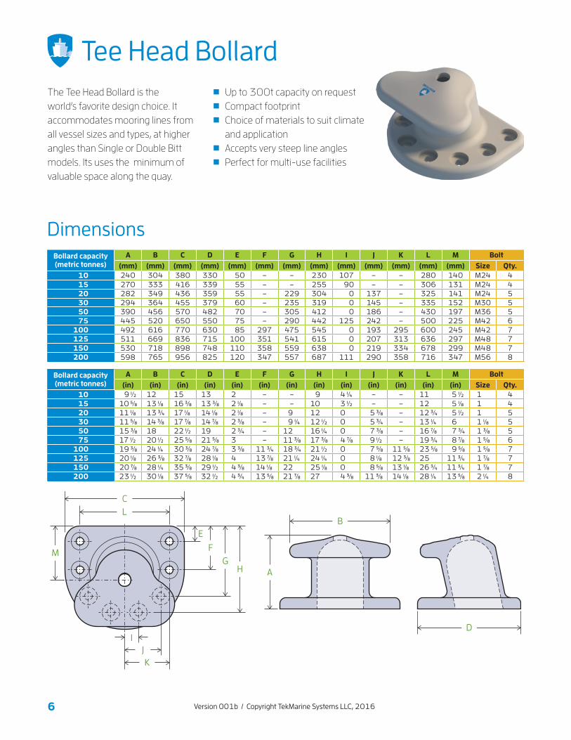
Tee Head BollardThe Tee Head Bollard is the world’s favorite design choice. It accommodates mooring lines from all vessel sizes and types, at higher angles than Single or Double Bitt models. Its uses the minimum of valuable space along the quay.
Bollard capacity (metric tonnes)
A B C D E F G H I J K L M Bolt(mm) (mm) (mm) (mm) (mm) (mm) (mm) (mm) (mm) (mm) (mm) (mm) (mm) Size Qty.
10 240 304 380 330 50 – – 230 107 – – 280 140 M24 4 15 270 333 416 339 55 – – 255 90 – – 306 131 M24 4 20 282 349 436 359 55 – 229 304 0 137 – 325 141 M24 5 30 294 364 455 379 60 – 235 319 0 145 – 335 152 M30 5 50 390 456 570 482 70 – 305 412 0 186 – 430 197 M36 5 75 445 520 650 550 75 – 290 442 125 242 – 500 225 M42 6100 492 616 770 630 85 297 475 545 0 193 295 600 245 M42 7125 511 669 836 715 100 351 541 615 0 207 313 636 297 M48 7150 530 718 898 748 110 358 559 638 0 219 334 678 299 M48 7200 598 765 956 825 120 347 557 687 111 290 358 716 347 M56 8
Bollard capacity (metric tonnes)
A B C D E F G H I J K L M Bolt(in) (in) (in) (in) (in) (in) (in) (in) (in) (in) (in) (in) (in) Size Qty.
10 9 1⁄2 12 15 13 2 – – 9 4 1⁄4 – – 11 5 1⁄2 1 4 15 10 5⁄8 13 1⁄8 16 3⁄8 13 3⁄8 2 1⁄8 – – 10 3 1⁄2 – – 12 5 1⁄8 1 4 20 11 1⁄8 13 3⁄4 17 1⁄8 14 1⁄8 2 1⁄8 – 9 12 0 5 3⁄8 – 12 3⁄4 5 1⁄2 1 5 30 11 5⁄8 14 3⁄8 17 7⁄8 14 7⁄8 2 3⁄8 – 9 1⁄4 12 1⁄2 0 5 3⁄4 – 13 1⁄4 6 1 1⁄8 5 50 15 3⁄8 18 22 1⁄2 19 2 3⁄4 – 12 16 1⁄4 0 7 3⁄8 – 16 7⁄8 7 3⁄4 1 3⁄8 5 75 17 1⁄2 20 1⁄2 25 5⁄8 21 5⁄8 3 – 11 3⁄8 17 3⁄8 4 7⁄8 9 1⁄2 – 19 3⁄4 8 7⁄8 1 5⁄8 6100 19 3⁄8 24 1⁄4 30 3⁄8 24 7⁄8 3 3⁄8 11 3⁄4 18 3⁄4 21 1⁄2 0 7 5⁄8 11 5⁄8 23 5⁄8 9 5⁄8 1 5⁄8 7125 20 1⁄8 26 3⁄8 32 7⁄8 28 1⁄8 4 13 7⁄8 21 1⁄4 24 1⁄4 0 8 1⁄8 12 3⁄8 25 11 3⁄4 1 7⁄8 7150 20 7⁄8 28 1⁄4 35 3⁄8 29 1⁄2 4 3⁄8 14 1⁄8 22 25 1⁄8 0 8 5⁄8 13 1⁄8 26 3⁄4 11 3⁄4 1 7⁄8 7200 23 1⁄2 30 1⁄8 37 5⁄8 32 1⁄2 4 3⁄4 13 5⁄8 21 7⁄8 27 4 3⁄8 11 3⁄8 14 1⁄8 28 1⁄4 13 5⁄8 2 1⁄4 8
Up to 300t capacity on request Compact footprint Choice of materials to suit climate and application
Accepts very steep line angles Perfect for multi-use facilities
FG
H
E
JK
I
CL
M
A
B
D
10 Version 001b / Copyright TekMarine Systems LLC, 2016
Materials
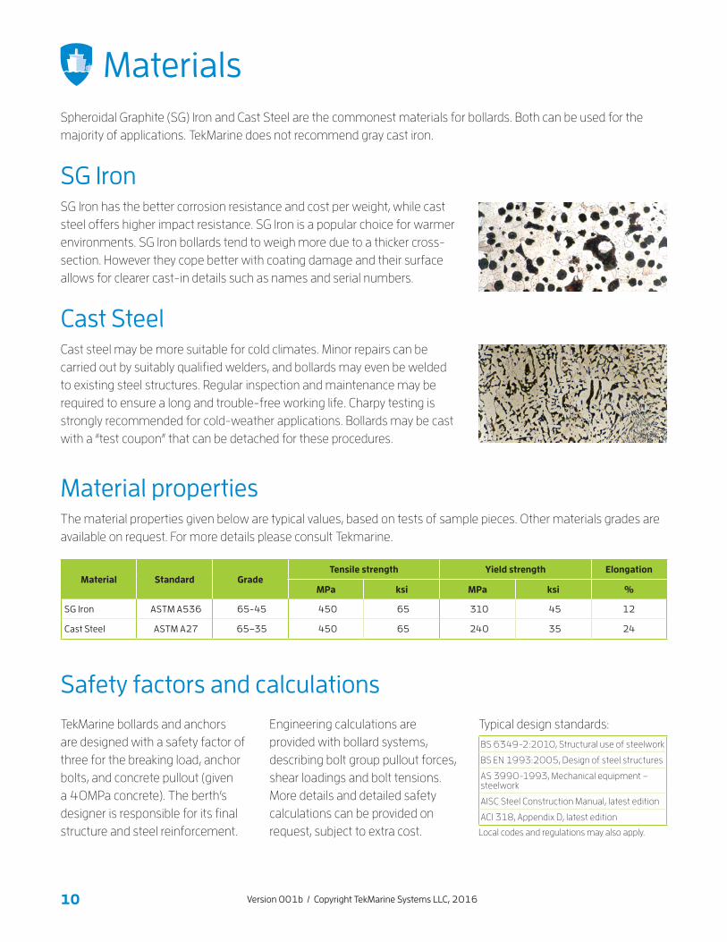
SG IronSG Iron has the better corrosion resistance and cost per weight, while cast steel offers higher impact resistance. SG Iron is a popular choice for warmer environments. SG Iron bollards tend to weigh more due to a thicker cross-section. However they cope better with coating damage and their surface allows for clearer cast-in details such as names and serial numbers.
Cast SteelCast steel may be more suitable for cold climates. Minor repairs can be carried out by suitably qualified welders, and bollards may even be welded to existing steel structures. Regular inspection and maintenance may be required to ensure a long and trouble-free working life. Charpy testing is strongly recommended for cold-weather applications. Bollards may be cast with a “test coupon” that can be detached for these procedures.
The material properties given below are typical values, based on tests of sample pieces. Other materials grades are available on request. For more details please consult Tekmarine.
TekMarine bollards and anchors are designed with a safety factor of three for the breaking load, anchor bolts, and concrete pullout (given a 40MPa concrete). The berth’s designer is responsible for its final structure and steel reinforcement.
Material properties
Safety factors and calculations
Material Standard GradeTensile strength Yield strength Elongation
MPa ksi MPa ksi %
SG Iron ASTM A536 65-45 450 65 310 45 12
Cast Steel ASTM A27 65–35 450 65 240 35 24
BS 6349-2:2010, Structural use of steelwork
BS EN 1993:2005, Design of steel structures
AS 3990-1993, Mechanical equipment – steelwork
AISC Steel Construction Manual, latest edition
ACI 318, Appendix D, latest edition
Spheroidal Graphite (SG) Iron and Cast Steel are the commonest materials for bollards. Both can be used for the majority of applications. TekMarine does not recommend gray cast iron.
Engineering calculations are provided with bollard systems, describing bolt group pullout forces, shear loadings and bolt tensions. More details and detailed safety calculations can be provided on request, subject to extra cost.
Typical design standards:
Local codes and regulations may also apply.

11Version 001b / Copyright TekMarine Systems LLC, 2016
Coating systems
Coating grades Sample C5M specificationCoating/preparation Standard Grade
Blasting ISO 12944 SA 2.5
Bituminous paint BS 3416:1991 Single coat
Corrosion resistant paint ISO 12944 C5M
Galvanized anchor bolts ISO 898-1:2013 Grade 8.8
Design guidelinesGuideline/code Details
Design Facilities Criteria
UFC 4-152-01 Design: Piers and Wharves. US Dept. of Defense, 2005 UFC 4-159-03 Design: Moorings. US Dept. of Defense, updated 2012.
OCIMF MEG3 Mooring Equipment Guidelines, 3rd Edition. Oil Companies International Marine Forum, 2008.
BS 6349-4 Maritime Works – Part 4: Code of practice for design of fendering and mooring systems. BSI 2014
ROSA 2000 Recommandations pour le calcul aux états-limites des ouvrages en site aquatique (Recommendations for calculating the limit states of works in water). METL/CETMEF, First edition, 2000.
ROM 3.1-99 Recommendations for Maritime Works. Puertos del Estado, 2000. English Edition 2007.– Part III, Vessel Manoevrability Characteristics – Part IV, External Actions on a Vessel
TR-6056-OCN Mooring Loads due to Parallel Passing Ships. Naval Facilities Engineering Services Center, 2005.
EAU 2012 Recommendations of the Committee for Waterfront Structures, Harbours and Waterways EAU 2012. Ernst & Sohn, 9th Edition, 2015.
Mooring and Anchoring Ships
Mooring and Anchoring Ships. Nautical Institute. Vol 1, 2003. Vol 2, 2009.
OCDI 1999 Technical Standards and Commentaries for Port and Harbour Facilities in Japan. Overseas Coastal Area Development Institute of Japan, English Edition, 2002.
Layer Number of coats
Thickness (μm)
2-part, zinc-rich epoxy primer 1 40–60
2-part epoxy primer 2–3 160–220
Acrylic top coat 1 60
Total (dry film) 4–5 320
Great care must be taken not to damage the bollard's original factory coating during installation. The recommended grade for long-term corrosion resistance in marine environments is C5M (ISO 12944). Suitable paints are supplied by International Paint (Akzo Nobel) among others. Other coatings, such as bituminous or primer, are available on request. Mooring Cleats are usually supplied painted, alternatively with a hot dip galvanized coating, and other finishes can be applied. Please ask TekMarine about the most suitable coating for your application.
Mooring lines continuously wear and abrade even the toughest coatings. We recommend a regular inspection and maintenance schedule, and repairs to the finish of any worn areas.
QualityTekMarine takes quality and safety seriously. Our typical package of quality documents includes:
Dimensioned drawings of bollards and anchors
Calculations on bollards and anchor systems
Installation advice
Casting inspection
Casting test report
Coating inspection/ test report
Others as required

12 Version 001b / Copyright TekMarine Systems LLC, 2016
Selecting bollardsOnce local regulations and applicable design standards have been taken into account, designers should consider:
Draft changes Water level changes Forces due to wind and currents Forces due to waves, swell and tides Forces due to ice (if required) The type, size and angle of mooring lines Anchor type and mounting method Overload prevention
When mooring loads cannot be calculated, the table of ship sizes provides a guideline. Allow for a 25% increase in bollard capacity if adverse loads are anticipated.
Ship sizes
Angles and spacing
Displacement Approx. bollard capacity (tonnes)
< 2,000 10
2,000–10,000 30
10,000–20,000 60
20,000–50,000 80
50,000–100,000 100
100,000–150,000 150
150,000–200,000 200
> 200,000 300
According to common codes, bollards should be spaced at intervals of 15% of the shortest ship design used on the berth. Spacings are commonly between 10–30m (30–90ft). This often coincides with fender placement or midway between fenders, or halfway between expansion joints on continuous structures.
Head and stern lines 45° ±15°Breast lines 90° ±30°Spring lines 5–10°Vertical line angle ≤25°
Mooring line angles should be calculated as part of a full mooring simulation. Vertical angles should be minimized. Horizontal angles are relative to the vessel’s main axis.
See PIANC, BS 6349-4 and ROM 3.1-99.
storm bollard
forward breastline spring lines
stern linebow line
fender
aft breastline
Fully laden Low draft
maximum freeboard
low tide
minimum freeboard
mean tidehigh tide
low tidemean tidehigh tide
13Version 001b / Copyright TekMarine Systems LLC, 2016
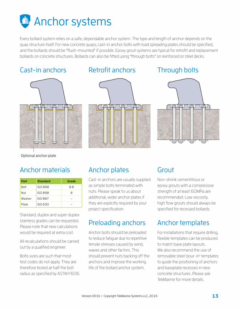
Anchor systems
Cast-in anchors
Anchor plates Grout
Preloading anchors
Anchor materials
Anchor templates
Retrofit anchors Through bolts
Cast-in anchors are usually supplied as simple bolts terminated with nuts. Please speak to us about additional, wider anchor plates if they are explicitly required by your project specification.
Non-shrink cementitious or epoxy grouts with a compressive strength of at least 60MPa are recommended. Low viscosity, high flow grouts should always be specified for recessed bollards.
Anchor bolts should be preloaded to reduce fatigue due to repetitive tensile stresses caused by wind, waves and other factors. This should prevent nuts backing off the anchors and improve the working life of the bollard anchor system.
Standard, duplex and super duplex stainless grades can be requested. Please note that new calculations would be required at extra cost.
All recalculations should be carried out by a qualified engineer.
Bolts sizes are such that most test codes do not apply. They are therefore tested at half the bolt radius as specified by ASTM F606.
For installations that require drilling, flexible templates can be produced to match base plate layouts. We also recommend the use of removable steel ‘pour-in’ templates to guide the positioning of anchors and baseplate recesses in new concrete structures. Please ask TekMarine for more details.
Every bollard system relies on a safe, dependable anchor system. The type and length of anchor depends on the quay structure itself. For new concrete quays, cast-in anchor bolts with load spreading plates should be specified, and the bollards should be “flush-mounted” if possible. Epoxy grout systems are typical for retrofit and replacement bollards on concrete structures. Bollards can also be fitted using “through bolts” on reinforced or steel decks.
Optional anchor plate
Part Standard Grade
Bolt ISO 898 8.8
Nut ISO 898 8
Washer ISO 887 –
Plate ISO 630 –
14 Version 001b / Copyright TekMarine Systems LLC, 2016
Other information
Vessels
Length LOA LOA
Displacement MD MD
Deadweight DWT DWT
Line angles
Min° Min°
Max° Max°
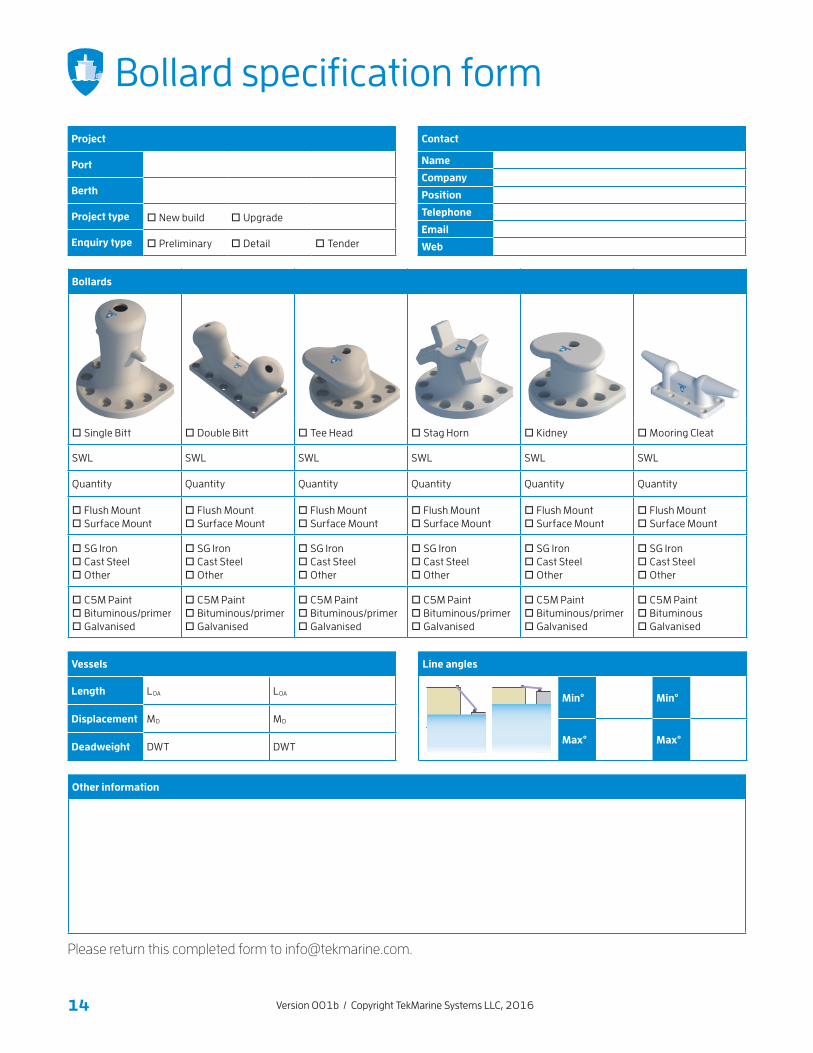
Bollards
□ Single Bitt □ Double Bitt □ Tee Head □ Stag Horn □ Kidney □ Mooring Cleat
SWL SWL SWL SWL SWL SWL
Quantity Quantity Quantity Quantity Quantity Quantity
□ Flush Mount □ Surface Mount
□ Flush Mount □ Surface Mount
□ Flush Mount □ Surface Mount
□ Flush Mount □ Surface Mount
□ Flush Mount □ Surface Mount
□ Flush Mount □ Surface Mount
□ SG Iron □ Cast Steel □ Other
□ SG Iron □ Cast Steel □ Other
□ SG Iron □ Cast Steel □ Other
□ SG Iron □ Cast Steel □ Other
□ SG Iron □ Cast Steel □ Other
□ SG Iron □ Cast Steel □ Other
□ C5M Paint □ Bituminous/primer □ Galvanised
□ C5M Paint □ Bituminous/primer □ Galvanised
□ C5M Paint □ Bituminous/primer □ Galvanised
□ C5M Paint □ Bituminous/primer □ Galvanised
□ C5M Paint □ Bituminous/primer □ Galvanised
□ C5M Paint □ Bituminous □ Galvanised
Project
Port
Berth
Project type □ New build □ Upgrade
Enquiry type □ Preliminary □ Detail □ Tender
Contact
Name
Company
Position
Telephone
Web
Bollard specification form
Please return this completed form to [email protected].
15Version 001b / Copyright TekMarine Systems LLC, 2016
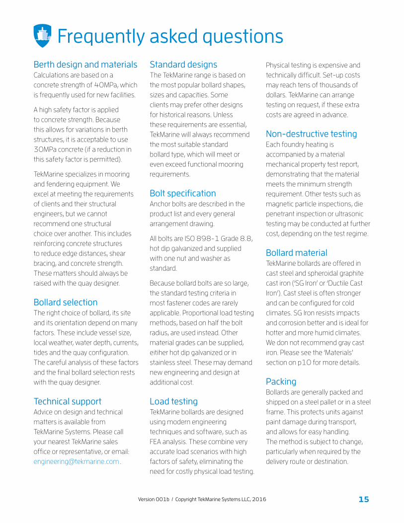
Frequently asked questionsBerth design and materialsCalculations are based on a concrete strength of 40MPa, which is frequently used for new facilities.
A high safety factor is applied to concrete strength. Because this allows for variations in berth structures, it is acceptable to use 30MPa concrete (if a reduction in this safety factor is permitted).
TekMarine specializes in mooring and fendering equipment. We excel at meeting the requirements of clients and their structural engineers, but we cannot recommend one structural choice over another. This includes reinforcing concrete structures to reduce edge distances, shear bracing, and concrete strength. These matters should always be raised with the quay designer.
Bollard selectionThe right choice of bollard, its site and its orientation depend on many factors. These include vessel size, local weather, water depth, currents, tides and the quay configuration. The careful analysis of these factors and the final bollard selection rests with the quay designer.
Technical supportAdvice on design and technical matters is available from TekMarine Systems. Please call your nearest TekMarine sales office or representative, or email: [email protected] .
Standard designsThe TekMarine range is based on the most popular bollard shapes, sizes and capacities. Some clients may prefer other designs for historical reasons. Unless these requirements are essential, TekMarine will always recommend the most suitable standard bollard type, which will meet or even exceed functional mooring requirements.
Bolt specificationAnchor bolts are described in the product list and every general arrangement drawing.
All bolts are ISO 898-1 Grade 8.8, hot dip galvanized and supplied with one nut and washer as standard.
Because bollard bolts are so large, the standard testing criteria in most fastener codes are rarely applicable. Proportional load testing methods, based on half the bolt radius, are used instead. Other material grades can be supplied, eitiher hot dip galvanized or in stainless steel. These may demand new engineering and design at additional cost.
Load testingTekMarine bollards are designed using modern engineering techniques and software, such as FEA analysis. These combine very accurate load scenarios with high factors of safety, eliminating the need for costly physical load testing.
Physical testing is expensive and technically difficult. Set-up costs may reach tens of thousands of dollars. TekMarine can arrange testing on request, if these extra costs are agreed in advance.
Non-destructive testingEach foundry heating is accompanied by a material mechanical property test report, demonstrating that the material meets the minimum strength requirement. Other tests such as magnetic particle inspections, die penetrant inspection or ultrasonic testing may be conducted at further cost, depending on the test regime.
Bollard materialTekMarine bollards are offered in cast steel and spheroidal graphite cast iron (‘SG Iron’ or ‘Ductile Cast Iron’). Cast steel is often stronger and can be configured for cold climates. SG Iron resists impacts and corrosion better and is ideal for hotter and more humid climates. We don not recommend gray cast iron. Please see the ‘Materials’ section on p10 for more details.
PackingBollards are generally packed and shipped on a steel pallet or in a steel frame. This protects units against paint damage during transport, and allows for easy handling. The method is subject to change, particularly when required by the delivery route or destination.
16 Version 001b / Copyright TekMarine Systems LLC, 2016
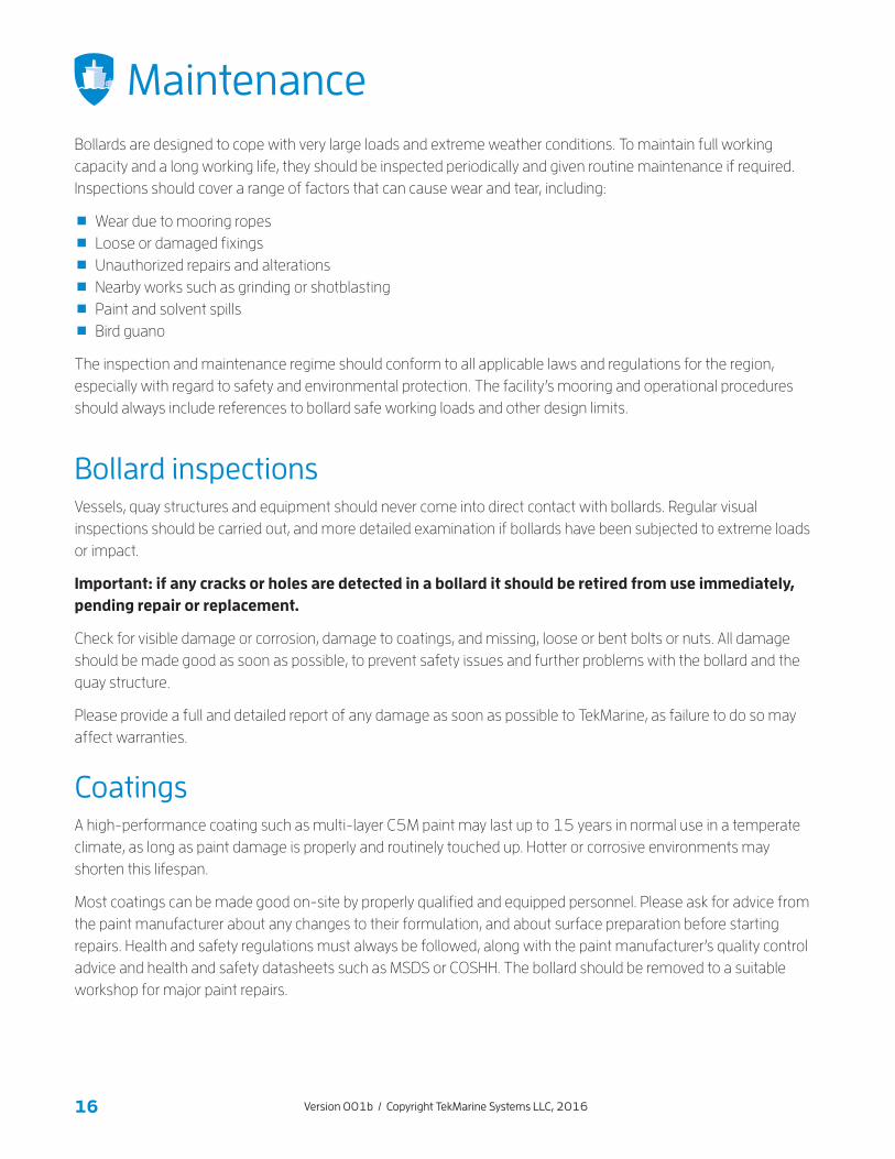
MaintenanceBollards are designed to cope with very large loads and extreme weather conditions. To maintain full working capacity and a long working life, they should be inspected periodically and given routine maintenance if required. Inspections should cover a range of factors that can cause wear and tear, including:
Wear due to mooring ropes Loose or damaged fixings Unauthorized repairs and alterations Nearby works such as grinding or shotblasting Paint and solvent spills Bird guano
The inspection and maintenance regime should conform to all applicable laws and regulations for the region, especially with regard to safety and environmental protection. The facility’s mooring and operational procedures should always include references to bollard safe working loads and other design limits.
Bollard inspectionsVessels, quay structures and equipment should never come into direct contact with bollards. Regular visual inspections should be carried out, and more detailed examination if bollards have been subjected to extreme loads or impact.
Important: if any cracks or holes are detected in a bollard it should be retired from use immediately, pending repair or replacement.
Check for visible damage or corrosion, damage to coatings, and missing, loose or bent bolts or nuts. All damage should be made good as soon as possible, to prevent safety issues and further problems with the bollard and the quay structure.
Please provide a full and detailed report of any damage as soon as possible to TekMarine, as failure to do so may affect warranties.
CoatingsA high-performance coating such as multi-layer C5M paint may last up to 15 years in normal use in a temperate climate, as long as paint damage is properly and routinely touched up. Hotter or corrosive environments may shorten this lifespan.
Most coatings can be made good on-site by properly qualified and equipped personnel. Please ask for advice from the paint manufacturer about any changes to their formulation, and about surface preparation before starting repairs. Health and safety regulations must always be followed, along with the paint manufacturer’s quality control advice and health and safety datasheets such as MSDS or COSHH. The bollard should be removed to a suitable workshop for major paint repairs.

17Version 001b / Copyright TekMarine Systems LLC, 2016
Maintenance
Anchors and fixingsUnless otherwise requested by the client, all TekMarine fixings are hot dip galvanized. Galvanized fixings rely on zinc deposits to protect against corrosion. These deposits typically last for about 5 years in the ‘splash’ zone of a temperate climate, and shorter periods in hotter or corrosive environments.
Inspections should look for depletion of the zinc layer or pitting to stainless steel. Non-destructive ultrasound testing may help to detect load damage to anchors below the quay surface. If in any doubt about anchor condition, please contact TekMarine for advice.
SparesIn the event of damage due to an incident, fixings can be relatively quick to order. Replacement bollards, however, have to be manufactured and transported to site. A small stock reserve will enable the facility to return to full operations much sooner.
Schedules
Part Inspection scheduleMaintenance schedule
Refer to notesInterim Full
Steel/cast iron bollards Yearly As necessary 15–25 years 1, 2, 4, 5
Paint/coating system Yearly As necessary 10 years 1, 2, 4
Anchors and fastenings Yearly As necessary 15–25 years 1, 3, 4
Notes1 As well as regular visual inspections, a closer visual inspection should follow any berthing incident, including exceptional impacts and
extreme load conditions. A complete record should immediately be made of each event.
2 Interim maintenance should include repairs to paintwork damaged by mooring lines, bird guano and other factors, as well as repairing
dents and similar damage due to overloads, accidents and extraordinary or unforeseen circumstances.
3 Interim maintenance should include the tightening of any loose fixings and the installation of preventative measures such as locking tabs
to prevent reoccurance, as well as the replacement of all missing or damaged fixings.
4 Full maintenance should follow a detailed inspection and the decision to replace, repair or refurbish any affected bollards, coatings and
fixings. The decision-making process and repairs should be carried out in consultation with an engineer approved by TekMarine.
5 No allowance is made for corrosion of steel or cast iron unless specified in the designs.
In case of any doubt about inspection or maintenance please contact TekMarine.
18 Version 001b / Copyright TekMarine Systems LLC, 2016
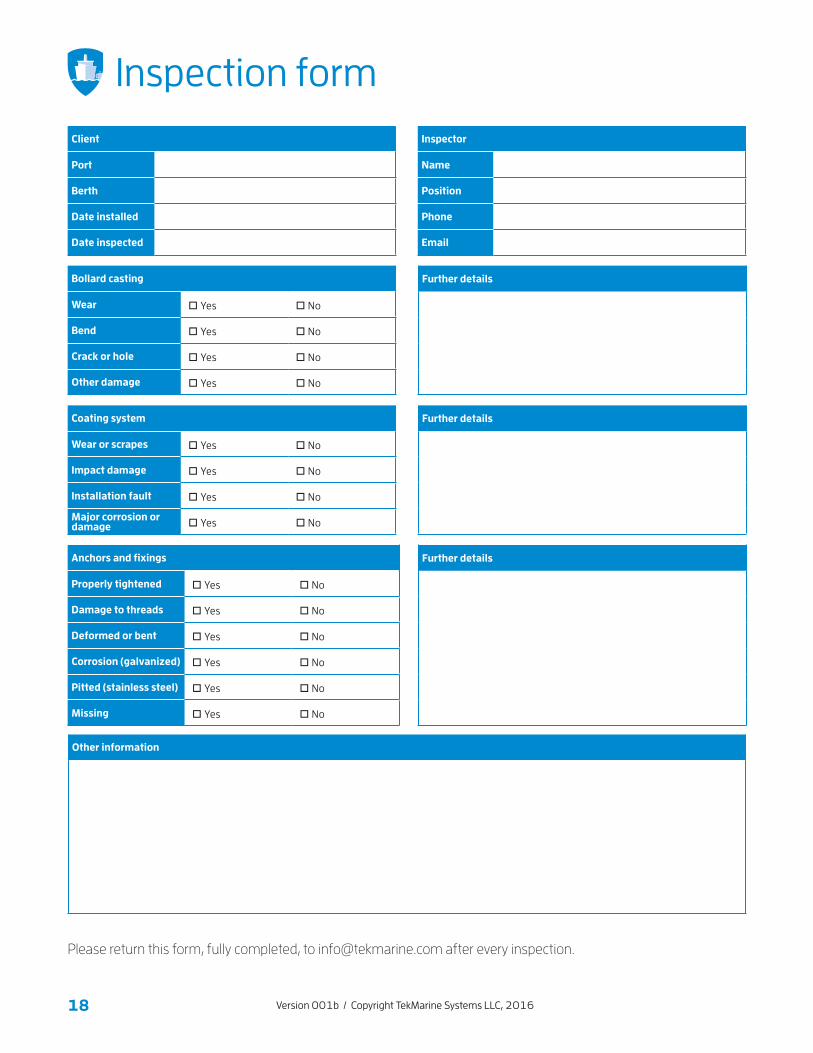
Inspection form
Please return this form, fully completed, to [email protected] after every inspection.
Other information
Bollard casting
Wear □ Yes □ No
Bend □ Yes □ No
Crack or hole □ Yes □ No
Other damage □ Yes □ No
Further details
We
Further details
We
Coating system
Wear or scrapes □ Yes □ No
Impact damage □ Yes □ No
Installation fault □ Yes □ No
Major corrosion or damage □ Yes □ No
Further details
We
Anchors and fixings
Properly tightened □ Yes □ No
Damage to threads □ Yes □ No
Deformed or bent □ Yes □ No
Corrosion (galvanized) □ Yes □ No
Pitted (stainless steel) □ Yes □ No
Missing □ Yes □ No
Client
Port
Berth
Date installed
Date inspected
Inspector
Name
Position
Phone
19Version 001b / Copyright TekMarine Systems LLC, 2016
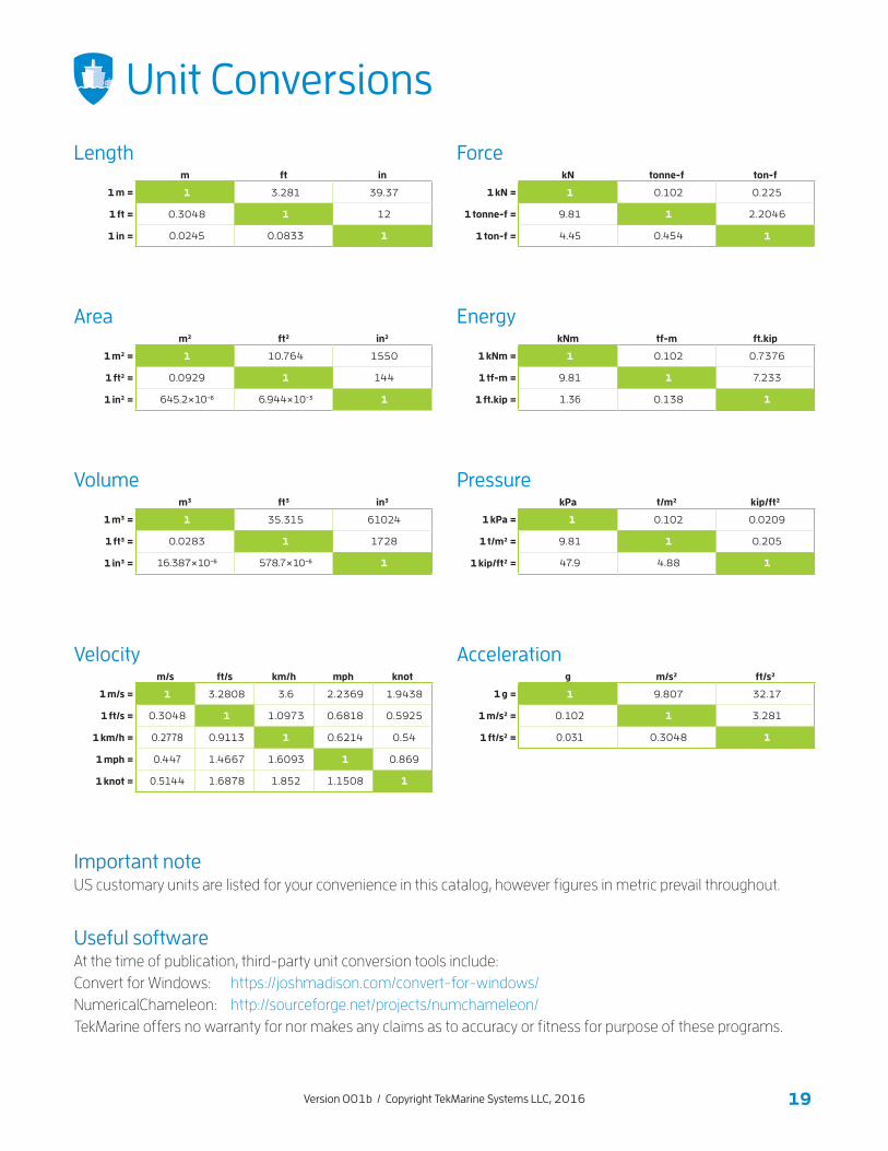
Unit Conversions
Lengthm ft in
1 m = 1 3.281 39.37
1 ft = 0.3048 1 12
1 in = 0.0245 0.0833 1
Aream2 ft2 in2
1 m2 = 1 10.764 1550
1 ft2 = 0.0929 1 144
1 in2 = 645.2 × 10⁻⁶ 6.944 × 10⁻³ 1
Volumem3 ft3 in3
1 m3 = 1 35.315 61024
1 ft3 = 0.0283 1 1728
1 in3 = 16.387 × 10⁻⁶ 578.7 × 10⁻⁶ 1
Accelerationg m/s2 ft/s2
1 g = 1 9.807 32.17
1 m/s2 = 0.102 1 3.281
1 ft/s2 = 0.031 0.3048 1
Velocitym/s ft/s km/h mph knot
1 m/s = 1 3.2808 3.6 2.2369 1.9438
1 ft/s = 0.3048 1 1.0973 0.6818 0.5925
1 km/h = 0.2778 0.9113 1 0.6214 0.54
1 mph = 0.447 1.4667 1.6093 1 0.869
1 knot = 0.5144 1.6878 1.852 1.1508 1
Important noteUS customary units are listed for your convenience in this catalog, however figures in metric prevail throughout.
Useful softwareAt the time of publication, third-party unit conversion tools include: Convert for Windows: https://joshmadison.com/convert-for-windows/ NumericalChameleon: http://sourceforge.net/projects/numchameleon/ TekMarine offers no warranty for nor makes any claims as to accuracy or fitness for purpose of these programs.
ForcekN tonne-f ton-f
1 kN = 1 0.102 0.225
1 tonne-f = 9.81 1 2.2046
1 ton-f = 4.45 0.454 1
EnergykNm tf-m ft.kip
1 kNm = 1 0.102 0.7376
1 tf-m = 9.81 1 7.233
1 ft.kip = 1.36 0.138 1
PressurekPa t/m2 kip/ft2
1 kPa = 1 0.102 0.0209
1 t/m2 = 9.81 1 0.205
1 kip/ft2 = 47.9 4.88 1

Presented by
Catalogue version 001b
TEKMARINE SYSTEMS LLC9595 Six Pines Drive, Suite 8210The Woodlands Houston, TX 77380, USA
phone +1 832 631-6104email [email protected] www.tekmarine.com
Recommended