AIR FORCE
TECHNOLOGY DEVELOPMENT AND TRANSITION STRATEGY (TDTS)
GUIDEBOOKVersion 2
July 2010
ACCESSABILITY: This publication is available via the Defense Acquisition University, Acquisition Community Connection (ACC) page -> Life Cycle Logistics Community -> Policy and Guidance -> Air Force.
RELEASABILITY: DISTRIBUTION STATEMENT A. Public Release
OPR: AFMC/A5S, 4375 Chidlaw Road, Wright-Patterson AFB, OH 45433
SUPERCEDES: Technology Development and Transition Strategy (TDTS) Guidebook, August 2009
This publication is intended for use by Program Managers and technology developers.This document is in the public domain and may be copied.
Feedback on this document is welcome. Please refer any feedback, questions, comments or corrections to HQ AFMC/A5S, [email protected] , 937-904-3558 (DSN 674-3558), AFMC/A5S, 4375 Chidlaw Road, Wright-Patterson AFB, OH 45433
SUMMARY OF CHANGES
Paragraph 1.1: Addition of a clarifying sentence
Paragraph 1.2: Deletion of an extraneous sentence
Paragraph 1.3: Re-title of the paragraph and addition of clarifying information
Paragraph 2.3: Deletion of a “requirement”, as this is a guide and not the appropriate document for this specific issue
Addition to Appendix 3 Glossary: Program Executive Officer (PEO)
2
Table of Contents
1 Introduction..........................................................................................................................................41.1 Problem Description.....................................................................................................................41.2 Big to Small..................................................................................................................................41.3 Deconfliction of TDTS Guidebook with other Required Documentation: TDS/Technology Transition Agreement (TTA)/SEP/Early Systems Engineering (SE)......................................................51.4 Purpose of This Guidebook...........................................................................................................6
2 Technology Transition Strategy Development....................................................................................72.1 Overview of Technology Transition Process................................................................................72.2 Why Use a Stage-Gate Process?...................................................................................................82.3 To Whom Does This Strategy Development Process Apply?....................................................102.4 Who Is Involved With This Process?..........................................................................................102.5 Timing.........................................................................................................................................112.6 Level of Approvals/Signature Authority.....................................................................................11
3 Stage Checklists and Gate Exit Criteria.............................................................................................123.1 Initial Tasks for Strategy Development......................................................................................123.2 Initial Strategy Requirements......................................................................................................123.3 Gate #3 (Exiting Proof-of-Concept Stage and Entering Refinement Stage)..............................133.4 Gate #4 (Exiting Refinement Stage and Entering Development Stage).....................................153.5 Gate #5 (Exiting Development Stage and Entering Prototype Stage)........................................173.6 Gate #6 (Exiting Prototype Stage to MS-B)...............................................................................20
4 Documenting the TDTS.....................................................................................................................224.1 TDTS Content Overview............................................................................................................22
4.1.1 Executive Summary.............................................................................................................234.1.2 Mission/Requirement...........................................................................................................234.1.3 Program Summary...............................................................................................................234.1.4 Program Management..........................................................................................................254.1.5 Business Strategy.................................................................................................................254.1.6 Program Risk Management.................................................................................................264.1.7 Cost and Performance Management....................................................................................274.1.8 Systems Engineering Approach...........................................................................................274.1.9 Test Approach......................................................................................................................284.1.10 Product Support Concept.....................................................................................................28
5 Summary............................................................................................................................................296 Bibliography......................................................................................................................................30Appendix 1 – Technology Readiness Level Definitions...........................................................................31Appendix 2 – Manufacturing Readiness Level Definitions......................................................................33Appendix 3 – Glossary..............................................................................................................................35Appendix 4 – Acronyms............................................................................................................................37Appendix 5 – Web Sites............................................................................................................................39
3
Technology Development and Transition Strategy (TDTS) Guidebook
1 Introduction
1.1 Problem Description A Government Accountability Office (GAO) study1 found that the Department of Defense
(DoD) routinely transitions immature technologies into its acquisition programs, thereby resulting in significant schedule delays, cost growth, and performance issues. Several recommendations were provided. One recommendation was to develop a gated process for developing and transitioning technology and to expand the use of technology transition agreements as one of the means to address this problem area. DoD concurred with this recommendation. This guidebook lays out a process for maturing technology and developing transition strategy based on a “stage-gate,” industry best practices approach.
The proposed exit criteria for each stage-gate are based on many factors, one of which is risk management. This will align both with DoD 5000 series instructions, which collectively serve as a reference resource for acquisition professionals and program management (PM) offices in dealing with system acquisition risks, and with the AFMCP 63-101 AFMC [Air Force Materiel Command] Risk Management Process, which provides PMs and their teams a basic understanding of the terms, definitions, and methods associated with effective risk management so that researchers and acquirers are speaking the same language.
1.2 Big to SmallThe crux of the problem lies in trying to transition technology that has not yet reached the stage
of development expected by the receiving agent. The transition process flow is a well-known and well-understood process, documented by the Office of the Secretary of Defense (OSD)2 and, as evidenced by its application of this approach in AFI 61-101 Applied Technology Council as well as various Major Command (MAJCOM) instructions, embraced by the Air Force (AF) for many years. Communication is paramount to developing and executing a long-term strategy that comprehensively spans technology maturation—from a given effort’s origins through a warfighter’s receipt of a new capability. A breakdown in communication obviously impedes not only strategic planning development, but also execution of the plan itself!
This Technology Development and Transition Strategy (TDTS) Guidebook details recognized best practices for developing a viable technology maturation strategy that fully addresses the transition of capabilities to users (intended MAJCOM customers). Despite widely propagated awareness of the transition process, the general guidelines of the past have proven insufficient to ensure success. Accordingly, the incorporation of a stage-gate process as an addition to the technology maturation cycle will help promote successful transitions by guiding vital communications among the key players of an effort.
Specifically, this stage-gate process will promote early, active, and ongoing involvement and collaboration among technology developers, acquisition program offices, and user representatives to
1 GAO-06-883 DoD Technology Transition, “BEST PRACTICES, Stronger Practices Needed to Improve DoD TechnologyTransition Processes,” September 2006.2 OSD Transition Practical Operating Guidelines (TPOG). DUSD (AS&C) in accordance with Under Secretary of Defense (Acquisition, Technology, and Logistics) (USD [AT&L]) and Director, Defense Research and Engineering (DDR&E).
4
establish a comprehensive strategy—a TDTS—broken into smaller, more manageable stages. Though it necessitates more upfront planning, a well-conceived TDTS that uses the stage-gate approach will form the basis for required acquisition documentation and thus save subsequent time and effort in preparing for milestone reviews. Essentially, the stage-gate process is analogous to designing an acquisition strategy around phases and milestones. Stages denote the periods wherein respective activities occur, while gates mark deliverable review points and enable management to make knowledge-based go/no-go decisions according to pre-established exit criteria. Adherence to this process is fundamental to developing a timely and cost-effective transition strategy.
In capturing technology maturation effort objectives from Concept Exploration and Refinement (CER); identifying relevant issues; and recommending a transition, acquisition, and management approach as well as a support strategy, the TDTS document serves as a strategic planning tool for the life cycle of the technology effort, including its integration with the follow-on acquisition program. The stage-gate process provides the framework for developing a transition strategy using a collaborative, multifunctional team, establishing what roles and responsibilities should remain in effect throughout the technology maturation and transition.
Additionally, the TDTS document addresses all facets of the strategy (technical and programmatic) needed for developing (maturing) required technologies while simultaneously readying critical technology elements for transition to the end user. Requisite TDTS content is similar to the Life-Cycle Management Plan (LCMP) for formal acquisition programs; consequently, the TDTS will feed the draft LCMP at Milestones (MS) A and B and also satisfy the Technology Development Strategy (TDS) requirement. Further, TDTS content will reflect the information needed for building the Systems Engineering Plan (SEP) throughout all stages and gates. However, it is important to note that in most instances, technologies are developed for transition into components or subcomponents of other systems as enabling capabilities (e.g., increased thrust, improved thermal management, sensor fusion). While these technologies themselves may not be designated for a formal acquisition Program of Record (PoR), they should integrate in some manner into an acquisition program or logistics activity. Technology efforts not supporting an acquisition PoR will not demand compliance with many of the acquisition documentation requirements; however, early deliberate planning and informed decision making will improve the likelihood of a successful transition.
Starting the strategy development and the stage-gate process early (i.e., once a MAJCOM customer is identified, and typically well before MS-A) will benefit every technology effort. Specifically, the process will drive a collaborative effort between the technology and acquisition communities to develop the transition strategy and a mutually agreed-upon technology maturation roadmap with well-defined cost, schedule, and performance parameters.
1.3 Deconfliction of TDTS Guidebook with other Required Documentation: TDS/Technology Transition Agreement (TTA)/SEP/Early Systems Engineering (SE)
The TDTS is a strategic planning tool to facilitate communication amongst a wide variety of individuals with a vested interest in a particular technology development activity. The focus of this TDTS Guidebook is to provide information about the best practices that are effective; it is not the intent to create a burdensome set of duplicitous documentation. The important aspect of this work is the collaboration to develop an effective strategy. It is encouraged that team members utilize existing information/documentation as source materials for the collaborative environment. Some of the documentation that is “replaced” by a TDTS, or has source information in other locations, is identified in this paragraph.
5
The TDTS document is designed to satisfy all needs of a TDS, including additional transition planning Therefore, as a given technology matures, the TDTS document becomes a “living” strategy—one that not only reflects the current state of the technology maturation effort relative to its ultimate transition to an acquisition program, but also satisfies the TDS requirement at MS-A. This milestone also indicates the starting point for building the draft LCMP. The stage-gate process revolves around technology transition that starts with a MAJCOM customer pull and ends at MS-B, and the TDTS document will eventually morph into the LCMP, which then undergoes approval both at the appropriate organizational levels and at the appropriate point (usually by MS-B) within the acquisition
TTA is the terminology used by OSD and other services (the AF refers to this document as a Technology Transition Plan, or TTP) that refers to a document identifying relevant issues surrounding the transition of a technology. A TTA/TTP typically involves participation from the technology, acquisition, and warfighting communities. The TDTS document is more comprehensive and has continuous support throughout the technology maturation and transition effort. The TTA/TTP is easily derived from the TDTS documentation. (Note: Upon availability of an automated tool, the TTA/TTP will simply be another report.)
Draft SEP development begins at program initiation, with the Concept Characterization and Technical Description (CCTD), and continues throughout SEP development as the program progresses, ultimately encompassing all SE requirements. TDTS Stage-Gates 3-6 represent a significant portion of the technical content of the initial SEP.
These complementary and dependent strategies provide senior management a framework for making decisions throughout the entire technology maturation cycle, including the technology’s transition into the acquisition process (via milestone review, contract award, partnering arrangements, and so on).
Since technology transition to (or from) industry is commonplace, the program office should release the TDTS Guidebook to industry as the accepted AF approach to technology maturation and transition planning. Early systems engineering is an approach for translating approved operational needs and requirements into operationally suitable systems. The approach consists of a top-down method, iterative throughout the technology maturation cycle and comprising requirements analysis; functional analysis and allocation; and design synthesis and verification for maintainability, reliability, interoperability, and survivability.
1.4 Purpose of This Guidebook This TDTS Guidebook is primarily designed to assist the creation of a technology maturation and
transition strategy. It also outlines who should participate and when, as well as what issues should be discussed, what approval authorities are necessary, and what type of documentation will ensure development of a comprehensive strategy. For a technology maturation effort, this guidebook (1) provides a stage-gate process that identifies the typical set of tasks associated with each stage and a recommended minimum set of corresponding exit criteria—which, in turn, ensure the technology maturation effort proceeds according to the strategic plan; and (2) outlines the topics to be addressed (and content to be included) in a strategy developed for a technology’s intended transition to the warfighter. Essentially, this TDTS Guidebook facilitates the creation of effort-specific TDTS documentation that captures the strategic roadmap for a technology destined for an end user.
6
2 Technology Transition Strategy Development
2.1 Overview of Technology Transition ProcessOSD3 “best practice” for transitioning technology includes the following key activities:
establishing a team, formulating the plan, developing information, coordinating and updating the information, obtaining commitment and approval at the proper stages, and executing transition (see top of Figure 1). This technology transition flow is understood by most technology developers and acquisition program managers. A key aspect of this flow is the iterative nature of technology maturation and transition activities, which requires a team of subject-matter experts collaborating across the development time frame. Without deliberate and proactive planning and coordination, the iterative nature of this flow can permit tasks or activities to “fall through the cracks,” increasing the likelihood that steps critical for successful transition will be missed.
3 OSD Transition Practical Operating Guidelines (TPOG). ibid.
7
8
Stage-Gate4
Stage-Gate5
Stage-Gate3
Prototype Relevant
Environment
Development Breadboard
Refinement BrassboardProof of Concept
Next PhaseMgmt Approve >Team Ready >
Stage-Gate Separate Phases
Establish a Team
Develop Information Commit and ApproveCoordinate & UpdateFormulate
Air ForceOSD
Technology TransitionAccepted Practice
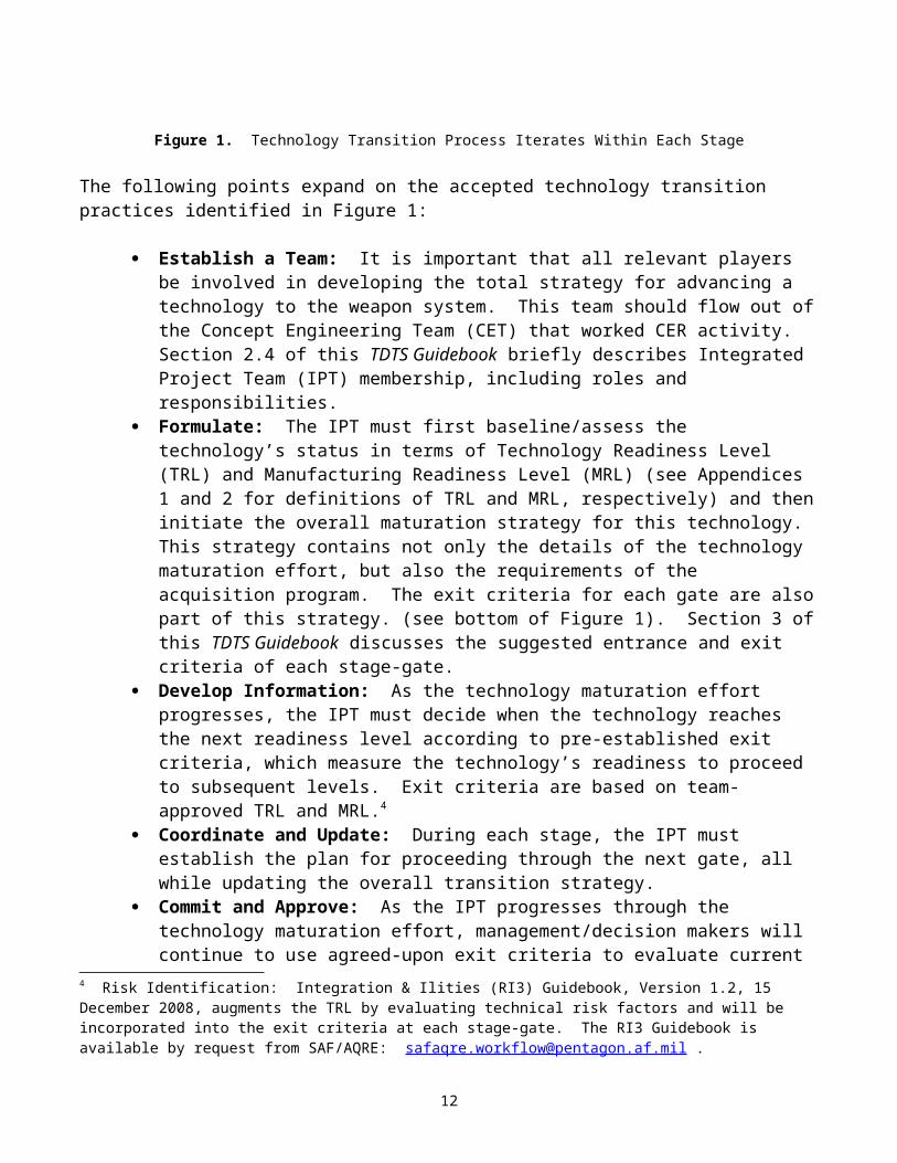
Figure 1. Technology Transition Process Iterates Within Each Stage
The following points expand on the accepted technology transition practices identified in Figure 1:
Establish a Team: It is important that all relevant players be involved in developing the total strategy for advancing a technology to the weapon system. This team should flow out of the Concept Engineering Team (CET) that worked CER activity. Section 2.4 of this TDTS Guidebook briefly describes Integrated Project Team (IPT) membership, including roles and responsibilities.
Formulate: The IPT must first baseline/assess the technology’s status in terms of Technology Readiness Level (TRL) and Manufacturing Readiness Level (MRL) (see Appendices 1 and 2 for definitions of TRL and MRL, respectively) and then initiate the overall maturation strategy for this technology. This strategy contains not only the details of the technology maturation effort, but also the requirements of the acquisition program. The exit criteria for each gate are also part of this strategy. (see bottom of Figure 1). Section 3 of this TDTS Guidebook discusses the suggested entrance and exit criteria of each stage-gate.
Develop Information: As the technology maturation effort progresses, the IPT must decide when the technology reaches the next readiness level according to pre-established exit criteria, which measure the technology’s readiness to proceed to subsequent levels. Exit criteria are based on team-approved TRL and MRL.4
Coordinate and Update: During each stage, the IPT must establish the plan for proceeding through the next gate, all while updating the overall transition strategy.
Commit and Approve: As the IPT progresses through the technology maturation effort, management/decision makers will continue to use agreed-upon exit criteria to evaluate current status of the effort and thereby make go/hold/no-go decisions, such as whether to continue toward the next stage or instead alter strategy/approach, to include potential delay or termination of the effort. These decision points employ the stage checklists shown in Section 3 to ensure that IPT and management decision makers ask the right questions at the right time.
2.2 Why Use a Stage-Gate Process?Figure 1 (top) illustrates the iterative nature of the current technology maturation and transition
process, as well as the tendency for this activity to occur over an extended period of time. The stage-gate approach is an industry-proven mechanism for effectively managing, directing, and otherwise controlling new product development efforts. As previously stated, stages denote periods during which certain activities occur, whereas gates enable knowledge-based deliverable reviews and, accordingly, informed decision making based on known criteria. Additionally—and critically—the stage-gate methodology identifies the intervals at which direction and/or level of work may undergo adjustment to ensure final product (or service) capacity to adequately meet MAJCOM customer needs.
Figure 1 (bottom) depicts the stage-gate process and its integration into traditional technology maturation stages (i.e., Proof of Concept, Breadboard, Brassboard, and Prototype). The stage-gate process manages technology maturation by dividing it into a predetermined set of events or activities developed specifically by period or phase (stage), each with a “transition review” (gate) having well-4 Risk Identification: Integration & Ilities (RI3) Guidebook, Version 1.2, 15 December 2008, augments the TRL by evaluating technical risk factors and will be incorporated into the exit criteria at each stage-gate. The RI3 Guidebook is available by request from SAF/AQRE: [email protected] .
9
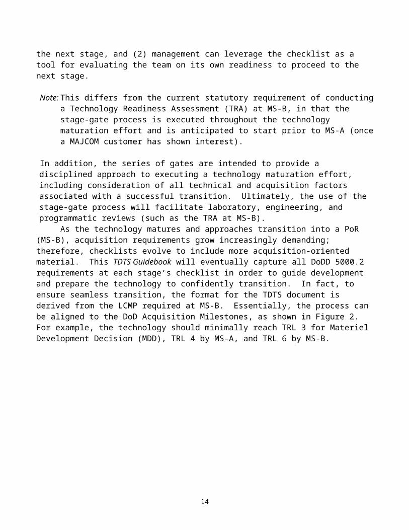
defined exit criteria. (Depending on the criticality of an effort, the current stage of the effort, and the particular acquisition program, the transition review may be a sizeable effort or may be integrated with scheduled annual program management reviews.) Since existing TRLs and MRLs are mature, well-established lexicons, the stage-gate process baseline reflects the alignment of TRL and MRL with traditional technology maturation stages. The process keeps its “eye on the prize,” generally building a strategy to get from TRL 3 through TRL 6 and transition to an acquisition program. At each gate awaits a recommended checklist that serves two purposes: (1) the team can tailor this checklist towards its own uniquely devised exit criteria for demonstrating the technology’s readiness to advance to the next stage, and (2) management can leverage the checklist as a tool for evaluating the team on its own readiness to proceed to the next stage.
Note: This differs from the current statutory requirement of conducting a Technology Readiness Assessment (TRA) at MS-B, in that the stage-gate process is executed throughout the technology maturation effort and is anticipated to start prior to MS-A (once a MAJCOM customer has shown interest).
In addition, the series of gates are intended to provide a disciplined approach to executing a technology maturation effort, including consideration of all technical and acquisition factors associated with a successful transition. Ultimately, the use of the stage-gate process will facilitate laboratory, engineering, and programmatic reviews (such as the TRA at MS-B).
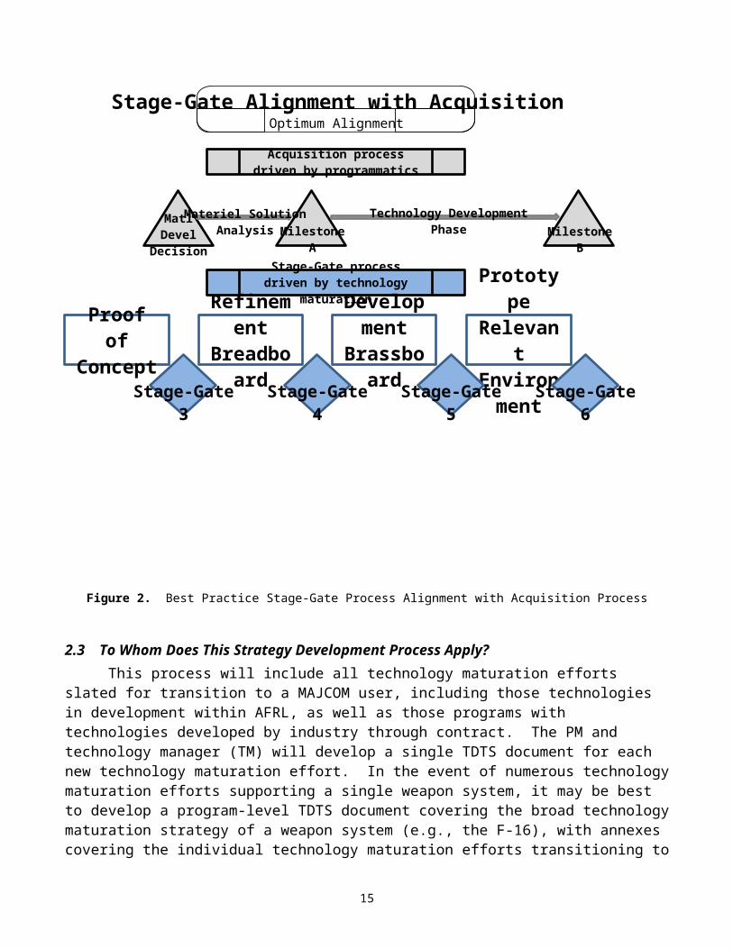
As the technology matures and approaches transition into a PoR (MS-B), acquisition requirements grow increasingly demanding; therefore, checklists evolve to include more acquisition-oriented material. This TDTS Guidebook will eventually capture all DoDD 5000.2 requirements at each stage’s checklist in order to guide development and prepare the technology to confidently transition. In fact, to ensure seamless transition, the format for the TDTS document is derived from the LCMP required at MS-B. Essentially, the process can be aligned to the DoD Acquisition Milestones, as shown in Figure 2. For example, the technology should minimally reach TRL 3 for Materiel Development Decision (MDD), TRL 4 by MS-A, and TRL 6 by MS-B.
10
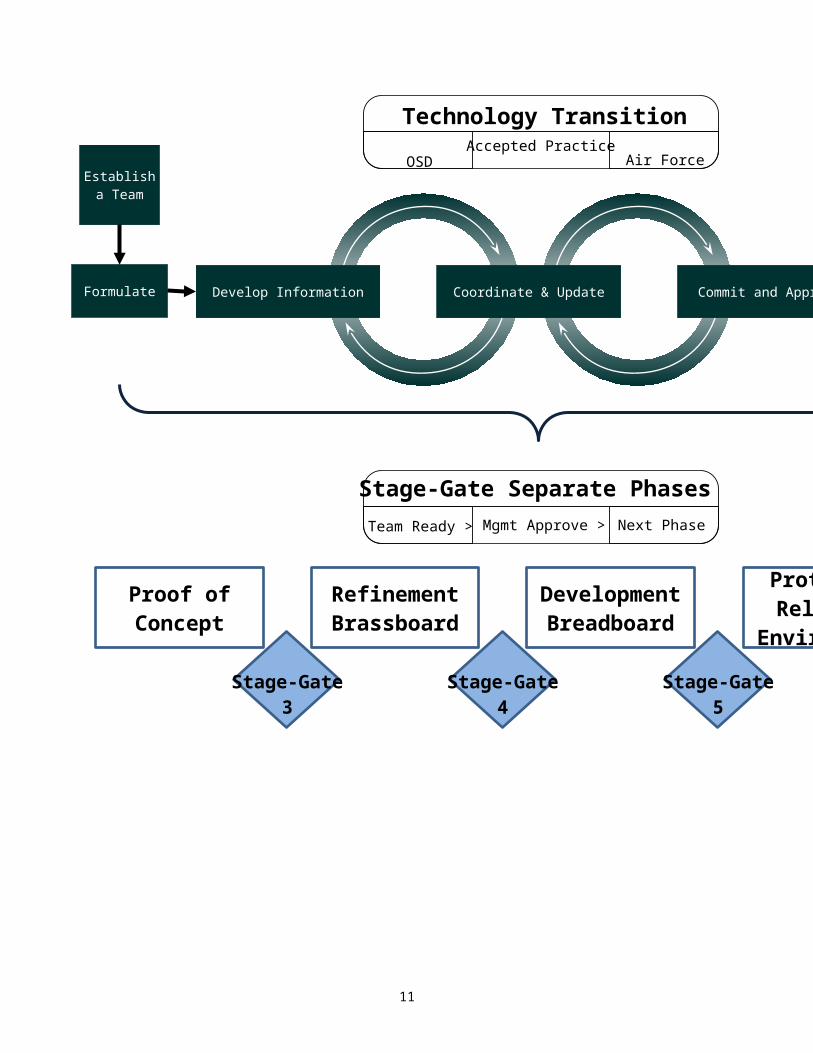
Figure 2. Best Practice Stage-Gate Process Alignment with Acquisition Process
2.3 To Whom Does This Strategy Development Process Apply?This process will include all technology maturation efforts slated for transition to a MAJCOM
user, including those technologies in development within AFRL, as well as those programs with technologies developed by industry through contract. The PM and technology manager (TM) will develop a single TDTS document for each new technology maturation effort. In the event of numerous technology maturation efforts supporting a single weapon system, it may be best to develop a program-level TDTS document covering the broad technology maturation strategy of a weapon system (e.g., the F-16), with annexes covering the individual technology maturation efforts transitioning to the weapon system (e.g., avionics, landing gear, and so on) and each such annex documenting the tailored technology transition management approach. This process may apply to technology maturation efforts with industry and should be called out in the Request for Proposal.
It must be acknowledged that the addition of the stage-gate process may result in an additional workload for Program Managers. At present, some, but far from all programs, utilize this methodology, for dealing with industry technology developers as well as AFRL.
11
Technology Development
Materiel Solution
Stage-Gate
Stage-Gate
Stage-Gate
Stage-Gate
Prototype Relevant
Environment
Development Brassboard
Refinement Breadboard
Proof of Concept
Stage-Gate process driven by technology maturation
Acquisition process driven by programmatics
Milestone
Milestone
MatlDevel
Decisio
Optimum Stage-Gate Alignment with
The TDTS Guidebook is a document that captures and explains those best practices that have been utilized successfully in government and industry.
2.4 Who Is Involved With This Process?The first step is identifying and standing up an IPT consisting of the stakeholders who will
collaborate to transition the technology to the end user. Best practices by OSD5 and GAO6, show that an IPT with technology/capability life-cycle participants would consist of the following members:
The PM (or designated acquisition representative) chairs the IPT, and the TM serves as co-chair. At minimum, the IPT should have the following representation: acquisition manager, appropriate engineers, acquisition intelligence personnel, appropriate technologists/science and technology specialists, technology or laboratory intelligence personnel, acquisition-sustainment logistician, development (and possibly operational) test representative(s), cost estimator, and contracting representative. In addition, representatives from the primary using MAJCOM (i.e., the follow-on acquisition program stakeholder) should be invited. This team should flow out of the CET that worked CER activity.
Each member’s role will take on varying degrees of involvement based on the appropriate stage. The IPT is expected to participate in all activities associated with the technology maturation and transition, including source selections (technology, acquisition, and insertion) and various reviews (program and other reviews). It is imperative to the process that the best resources are assigned as the means for achieving successful transition. Accordingly, contractors should be included as appropriate (primes, subs, and so on).
Each of the technology maturation and follow-on acquisition program’s stakeholders (i.e., MAJCOMs) should be involved in the transition strategy. The nature of stakeholder involvement in the transition strategy depends primarily on program size and complexity. Not all stakeholders need be involved from the very start. However, the IPT should bring them into the process as soon as activity/progress necessitates doing so.
Other participating service or governmental agencies should provide representation as necessary to ensure interoperability and consistency with future joint concept of operations (CONOPS) activity.
Further, since industry also has a role in managing and executing program requirements, PMs should engage industry partners early in the transition strategy development process. Early and continuous involvement with both industry and sustainment organizations, enhances cooperative relationships and maximizes opportunities for a successful technology maturation and follow-on acquisition program.
2.5 TimingThe strategy and associated TDTS documentation should be developed prior to any obligation of
funds or contract award. The strategy developed by the team will guide the contractual effort and should be refined as the project progresses.
The strategy, and therefore the TDTS document, undergoes update throughout the technology maturation effort as each gate is completed. These planned gate updates, which provide additional data and artifacts, are not considered amendments.
An amendment to the original TDTS document must be prepared if a significant change occurs, as determined by the IPT. The changes may be because of changes to the work effort in the areas of
5 OSD Transition Practical Operating Guidelines (TPOG). ibid.6 GAO-06-883 DoD Technology Transition, ibid.
12
Cost, Schedule, Performance, Feasibility, Scope, Contract Type, Readiness Levels, or Funding, or may be requests or direction from senior leadership (e.g., Milestone Decision Authority (MDA), AF Acquisition Executive (AFAE), Program Executive Officer (PEO), AFMC Commander, AFRL Commander). If a significant change occurs to a technology maturation effort and/or the associated program, the PM/TM prepares and submits an amended TDTS document (or an annex) with a statement summarizing the changes. The amendment should reflect the current status of the action(s) described, with all changes identified by a vertical bar in the margin. All TDTS document amendments require approval (see Section 2.6).
2.6 Level of Approvals/Signature AuthorityThere are three minimum required signatures: the responsible TM (proper industry
representative or AFRL Commander), the PEO or his or her delegated representative, and the MAJCOM/customer.
Approval is indicated on the TDTS document and includes typed name and title, signature of the approving official, and date signed. If an individual is approving only a portion of the TDTS document, the specific portion being approved should be noted next to the approving official’s signature block.
The IPT identifies all offices needed for coordinating on the TDTS package. All signature agencies should be represented on the IPT in order to ensure early involvement and thus minimize coordination time. Where possible, documentation should be staffed in parallel to consolidate and/or minimize the coordination time.
13
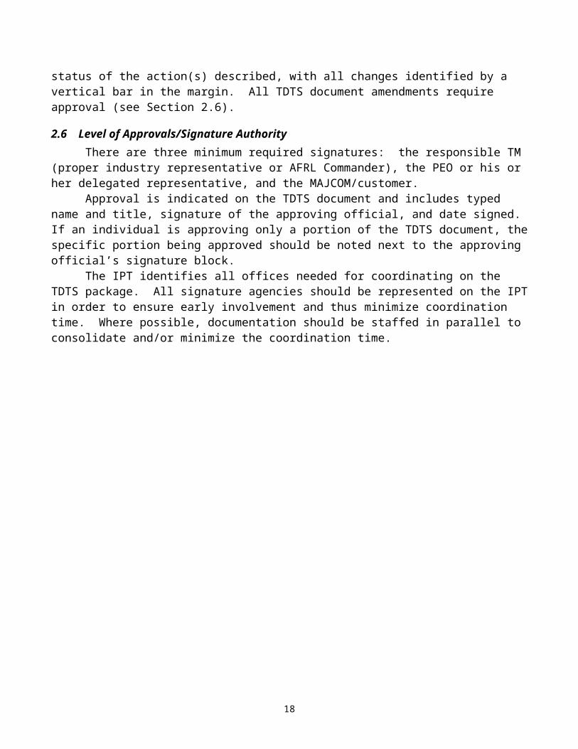
3 Stage Checklists and Gate Exit Criteria
This section describes best practice stage checklists and gate exit criteria. Depending on the results of the initial baseline assessment, the technology effort could enter the process at Stage-Gate 3, 4, or 5. To reiterate, if exit criteria are not met—for example, if a Stage-Gate 3 MRL assessment is not at the best practice standard—managerial discretion must determine whether the risk is manageable and, thus, whether the team should proceed to the next stage.
3.1 Initial Tasks for Strategy DevelopmentFollowing are the strategy development start-up tasks:
Document the technology and the overall concept for the project. Uses the CCTD/Analysis of Alternatives (AoA) documents from CER to build the baseline proof
of concept Define the technology maturity strategy goals and objectives. Identify stakeholders (see Section 2.4), including the following:
Project sponsor for the technology maturation effort Project acquirer for follow-on acquisition program End user for the final capability
Document roles and responsibilities. Identify the end-user need being satisfied by this technology concept, and document the following:
Any weapon system roadmap(s) that this technology is supporting User significance (importance) for having this technology concept Warfighting capability that this technology concept is addressing
Identify Program Protection issues, including Critical Program Information (even if potential) and the associated Security Classification Guide and Distribution Statement
3.2 Initial Strategy RequirementsFollowing are the initial strategy requirements:
Create IPT (Section 2.4) to address technology and programmatic questions, to include the following representation: Chair (PM), co-chair (TM), team members representing appropriate engineers, acquisition
intelligence personnel, appropriate technologists/science and technology specialists, acquisition-
14
Stage-Gate
Stage-Gate
Stage-Gate
Stage-Gate
Prototype Relevant
Environment
Development Brassboard
Refinement Breadboard
Proof of Concept
MS- MS-MD
sustainment logistician, development (and possibly operational) test representative(s), cost estimator, contracting representative, and MAJCOM representative/customer. This team should flow out of the CET that worked CER activity.
Team for (1) determining initial (current) TRL of the technology in order to identify the stage at which the technology effort enters the process; (2) for developing project-specific definitions for each technology readiness level term (i.e., Brassboard, Breadboard, Prototype and Relevant Environment); and (3) for developing a TRL plan indicating project-specific TRL exit criteria for the technology maturation effort including measurable metrics for each of the exit criteria.
Team for (1) determining initial (current) MRL of the technology, and (2) developing an MRL plan indicating MRL exit criteria for the technology maturation effort.
Team for determining (1) software requirements and (2) identifying if accreditation and certification must be obtained. [Note: NDAA Certification can take between 12-18 months to obtain, and MUST be complete prior to expenditure of funds.]
Initiate documentation of the strategy (i.e., the TDTS document).
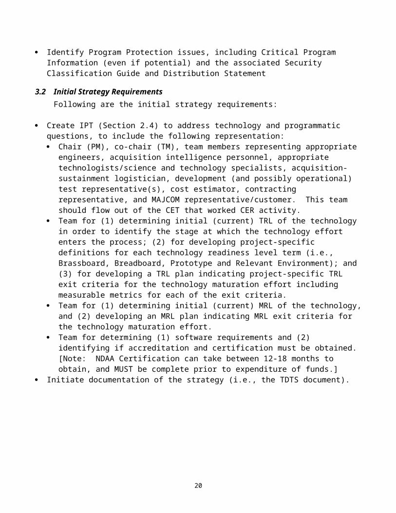
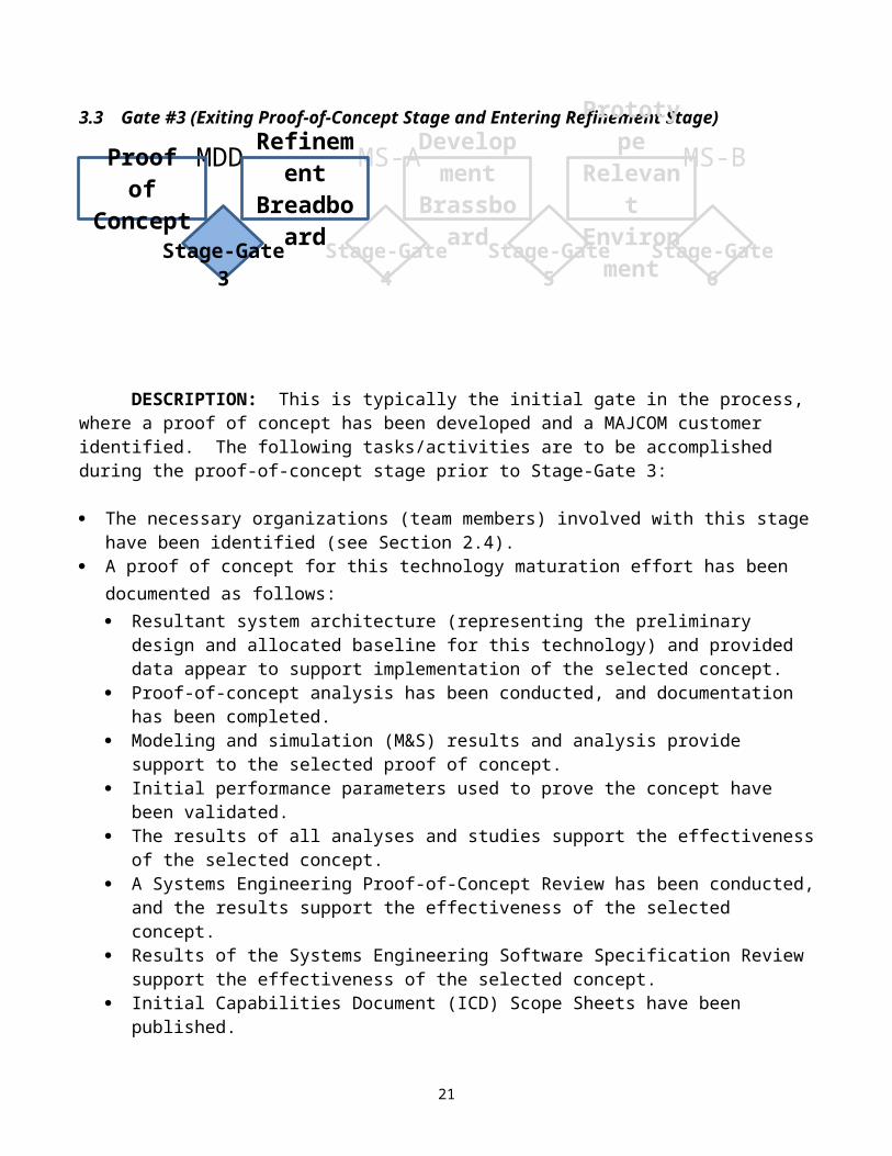
3.3 Gate #3 (Exiting Proof-of-Concept Stage and Entering Refinement Stage)
DESCRIPTION: This is typically the initial gate in the process, where a proof of concept has been developed and a MAJCOM customer identified. The following tasks/activities are to be accomplished during the proof-of-concept stage prior to Stage-Gate 3:
The necessary organizations (team members) involved with this stage have been identified (see Section 2.4).
A proof of concept for this technology maturation effort has been documented as follows: Resultant system architecture (representing the preliminary design and allocated baseline for this
technology) and provided data appear to support implementation of the selected concept. Proof-of-concept analysis has been conducted, and documentation has been completed. Modeling and simulation (M&S) results and analysis provide support to the selected proof of
concept. Initial performance parameters used to prove the concept have been validated. The results of all analyses and studies support the effectiveness of the selected concept. A Systems Engineering Proof-of-Concept Review has been conducted, and the results support
the effectiveness of the selected concept. Results of the Systems Engineering Software Specification Review support the effectiveness of
the selected concept.
15
Stage-Gate
Stage-Gate
Stage-Gate
Stage-Gate
Prototype Relevant
Environment
Development Brassboard
Refinement Breadboard
Proof of Concept
MS- MS-MD
Initial Capabilities Document (ICD) Scope Sheets have been published. Software requirements have been identified, and accreditation and certification issues are being
worked. [Note: NDAA Certification can take between 12-18 months to obtain, and MUST be complete prior to expenditure of funds.]
The initial TDTS has been documented in accordance with Section 4 of this TDTS Guidebook.
The CCTD has been updated.
The initial draft of the SEP has begun. (Note: Upon availability of an automated tool, the SEP will simply be another report).
Program Protection Plan (PPP) has been documented.
A Breadboard Laboratory Validation Plan for the Refinement stage has been documented as follows: Breadboard purpose, objectives, and scope have been described. The critical functions that will
be the focus of the technology concept proved in the next stage are known and understood. System performance parameters have been properly identified and vetted with the MAJCOM
customer. The appropriate test requirements have been vetted with the MAJCOM customer. A detailed technical description of the objective system—including the test configurations, key
functions, and subsystems targeted for insertion, as well as an understanding of the (objective and test) system concept—has been provided.
The scenario for each planned test has been adequately described, to include environment, facilities, operational considerations, and imposed constraints. The plan for conducting each test has been described, including location, responsible and
participating organizations, procedures, and data to be collected. A schedule showing the timeline for the preparation and conduct of each planned test has
been provided. All external systems and organizations participating in the test have been identified, and
coordination with technology transition partners has been accomplished. Key technology system and subsystem items (hardware, software, algorithms) to be tested in
the Breadboard Laboratory Validation have been identified, and the test approach has been accepted.
The threats to the warfighter addressed by the technology have been accurately documented. The methods for representing threats, establishing the test environment and instrumentation, and
specifying special test equipment have been adequately described. The data reduction and analysis methods for determining results based on content, quality,
quantity and completeness have been described. Analyses, simulations, and/or tests to be performed have been identified, with developmental
needs addressed. A schedule and cost projections for completing the next stage have been developed, and costs are
covered by funding sources.
16
A risk assessment7 has been conducted and documented, and the level of risk is acceptable to management.
EXIT CRITERIA GATE #3:1. TRL 3; MRL per MRL plan.2. Technology concept has been proven sufficient to meet the user need in a laboratory
environment, and a proof-of-concept has been documented.3. The TDTS document has been approved (see Section 2.6), and an acquisition agency has shown
a level of interest. (Note: “Interest” simply affirms the potential for transition should the project succeed and meet certain stage-specific exit criteria [TRL 3 and/or MDD].)
4. A Breadboard Laboratory Validation Plan for the Refinement stage has been developed, with purpose, objectives, and scope adequately described.
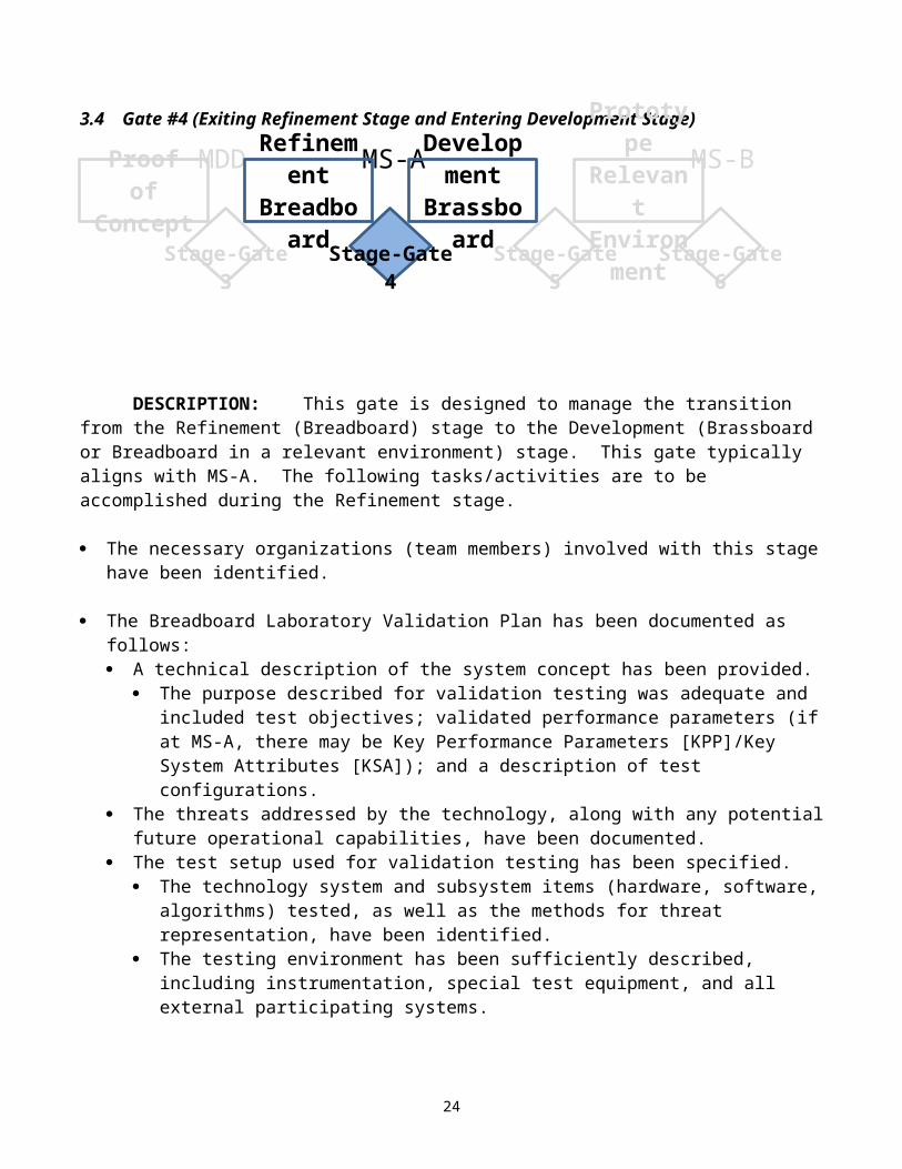
3.4 Gate #4 (Exiting Refinement Stage and Entering Development Stage)
DESCRIPTION: This gate is designed to manage the transition from the Refinement (Breadboard) stage to the Development (Brassboard or Breadboard in a relevant environment) stage. This gate typically aligns with MS-A. The following tasks/activities are to be accomplished during the Refinement stage.
The necessary organizations (team members) involved with this stage have been identified.
The Breadboard Laboratory Validation Plan has been documented as follows: A technical description of the system concept has been provided.
The purpose described for validation testing was adequate and included test objectives; validated performance parameters (if at MS-A, there may be Key Performance Parameters [KPP]/Key System Attributes [KSA]); and a description of test configurations.
The threats addressed by the technology, along with any potential future operational capabilities, have been documented.
The test setup used for validation testing has been specified.
7 This can be satisfied by the application of the RI3 Guidebook methodology, or any other approved risk assessment tool.
17
Stage-Gate
Stage-Gate
Stage-Gate
Stage-Gate
Prototype Relevant
Environment
Development Brassboard
Refinement Breadboard
Proof of Concept
MS- MS-MD
The technology system and subsystem items (hardware, software, algorithms) tested, as well as the methods for threat representation, have been identified.
The testing environment has been sufficiently described, including instrumentation, special test equipment, and all external participating systems.
A detailed test description including test schedule and location, organizations involved, test results, outstanding issues, analysis results of simulation, operational considerations, and technology constraints and limitations is available.
A description of each test (i.e., how it was conducted) has been provided. The technical results from the validation effort have been provided.
The methods for determining and assessing results based on content, quality, quantity, and completeness have been described, including all analyses performed, results documented, and problems encountered.
Data collected from the Breadboard validation effort has been provided. Preliminary determinations of deficiencies, shortcomings, and suggested improvements have
been provided. A Performance Results Matrix has been populated and provided.
Recommendations from the Breadboard validation effort have been developed and provided. Risk assessment8 has been updated based on validation effort data and results. Results from the Breadboard Validation Review and/or the Preliminary Design Review (if
conducted) have been provided. Hazard identification and analysis results have been provided. Safety requirements applied during validation testing have been provided. Form, fit, and function parameters have been updated.
The initial TDTS documentation has been updated.
The CCTD has been updated.
The initial draft of the SEP has begun.
PPP has been updated.
Initial draft of the LCMP or equivalent (for non-PoR efforts) has begun.
A Brassboard-Relevant Environment Validation Plan for the Development stage has been documented as follows: The purpose, objectives, and scope of the Brassboard-Relevant Environment Validation Plan
have been described. The critical functions that will be the focus of the key technology concept proven in the next stage are known and understood.
The system performance parameters that will be validated have been properly identified. The appropriate requirements are being validated. A detailed technical description of the objective system—including the test configurations, key
functions, and subsystems targeted for insertion, as well as an understanding of the (objective and test) system concept—has been provided.
8 This can be satisfied by the application of the RI3 Guidebook methodology, or any other approved risk assessment tool.
18
The scenario for each planned test has been adequately described, to include environment, facilities, operational considerations, and imposed constraints. The plan for conducting each test has been described, including location, responsible and
participating organizations, procedures, and data to be collected. A schedule showing a timeline for the preparation and conduct of each planned test has been
provided. All external systems and organizations participating in the test have been identified, and
coordination with technology transition partners has been accomplished. Key technology system and subsystem items (hardware, software, algorithms) to be tested in
the Brassboard-Relevant Environment Validation have been identified, and their test approach has been validated.
The threats to the warfighter addressed by the technology have been accurately documented. The methods for representing threats, establishing the test environment and instrumentation, and
specifying special test equipment have been adequately described. The data reduction and analysis methods for determining results based on content, quality,
quantity and completeness have been described. Analyses, simulations, and/or tests to be performed have been identified, with developmental
needs addressed. A schedule for completing the next stage has been developed. Cost projections for the next stage have been developed, supported (justified), and covered by
funding sources. A risk assessment9 has been accomplished and evaluated, and a decision to proceed has been
adopted.
EXIT CRITERIA GATE #4:1. TRL 4; MRL per MRL plan.2. The technology breadboard has been demonstrated to operate in a laboratory environment, and a
Breadboard Laboratory Validation Report has been documented.3. The TDTS document has been updated, and an acquisition agency has demonstrated a level of
intent. (Note: “Intent” refers to the PEO/PM to receive the project for commencement of the acquisition phase at a later date and to initiate Program Objective Memorandum [POM] funding if required [TRL 4 and/or MS-A].)
4. A Brassboard-Relevant Environment Validation Plan has been developed, with purpose, objectives, and scope adequately described.
9 This can be satisfied by the application of the RI3 Guidebook methodology, or any other approved risk assessment tool.
19
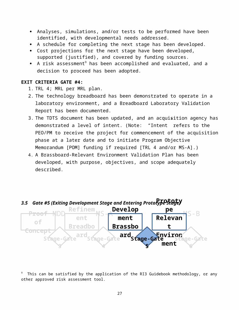
3.5 Gate #5 (Exiting Development Stage and Entering Prototype Stage)
DESCRIPTION: This gate is designed to manage the transition from the Development (Brassboard) stage to the Prototype-Relevant Environment stage. The following tasks/activities are to be accomplished during the Development stage.
The necessary organizations (team members) involved with this stage have been identified.
The Brassboard-Relevant Environment Validation Plan has been documented as follows: A technical description of the system concept has been provided.
The purpose described for validation testing was adequate and included test objectives, MAJCOM customer-vetted performance parameters, and a description of test configurations.
The threats addressed by the technology, along with any potential future operational capabilities, have been accurately documented.
The test setup used for validation testing has been specified. The technology system and subsystem items (hardware, software, algorithms) tested, as well
as the methods for threat representation, have been identified. The key technology system and subsystem items (hardware, software, algorithms) tested, as
well as the methods for threat representation, have been identified. The criteria for each test have been provided. The testing environment has been sufficiently described, including instrumentation, special
test equipment, and all external participating systems. A detailed test description including test schedule and location, organizations involved, test
results, outstanding issues, analysis results of simulation, operational considerations, and technology constraints and limitations is available.
A description of each test (i.e., how it was conducted) has been provided. The technical results from the validation effort have been provided.
The methods for determining and assessing results based on content, quality, quantity, and completeness have been described, including all analyses performed, results documented, problems encountered.
Data collected from the Brassboard validation effort has been provided. Preliminary determinations of deficiencies, shortcomings, and suggested improvements have
been provided. A Performance Results Matrix has been populated and provided.
Recommendations from the Brassboard validation effort have been developed and provided.
20
Stage-Gate
Stage-Gate
Stage-Gate
Stage-Gate
Prototype Relevant
Environment
Development Brassboard
Refinement Breadboard
Proof of Concept
MS- MS-MD
Technology risk assessment10 has been updated based on validation effort data and results. Results from the Brassboard-Relevant Environment Review and/or the Preliminary Design
Review (if conducted) have been provided. Hazard identification and analysis results have been provided. Safety requirements applied during validation testing have been provided. Form, fit, and function parameters have been updated. A performance results matrix documenting the results of conducted tests has been provided. Preliminary determinations of deficiencies, shortcomings, and suggested improvements have
been provided.
The TDTS documentation has been updated.
The CCTD has been updated.
The SEP has been updated.
PPP has been updated.
The draft LCMP or equivalent (for non-PoR efforts) has been updated.
A Prototype-Relevant Environment Validation Plan for the Prototype stage has been developed as follows: Purpose, objectives, and scope have been adequately described. All external systems and organizations participating in the test have been identified, and
coordination with Technology Transition partners has been accomplished. System performance parameters that will be validated have been properly identified. A detailed technical description of the objective system—including the test configurations, key
functions and subsystems targeted for insertion, as well an understanding of the (objective and test) system concept—has been provided.
Key technology system and subsystem items (hardware, software, algorithms) to be tested in the Prototype-Relevant (or simulated operational) Environment Validation have been identified, and their test approach has been validated.
The plan for conducting each test has been described including location; responsible and participating organizations; procedures; and data to be collected.
A schedule showing a timeline for the preparation and conduct of each planned test has been provided.
Analyses, simulations and/or tests to be performed have been identified, with developmental needs addressed.
The scenario for each planned test has been adequately described, to include environment, facilities, operational considerations, and imposed constraints.
The threats to the warfighter addressed by the technology have been accurately documented. Anti-tamper issues have been documented in the PPP.
The methods for representing threats, establishing the test environment and instrumentation, and specifying special test equipment have been adequately described.
The appropriate requirements are being validated.
10 This can be satisfied by the application of the RI3 Guidebook methodology, or any other approved risk assessment tool.
21
A risk assessment11 has been accomplished and evaluated, and a decision to proceed has been adopted.
EXIT CRITERIA GATE #5:1. TRL 5; MRL per MRL plan.2. The Development Brassboard has been demonstrated to operate in a relevant environment, and a
Brassboard Laboratory Validation Report has been documented.3. TDTS documentation has been updated, and the acquisition agency has demonstrated a level of
commitment. (Note: “Commitment” entails the firm resolve of all stakeholders to transition and fund (POM for) the technology. The technology performance has been demonstrated to meet PEO/PM capability [TRL 5 and/or MS-B].)
4. A Prototype-Relevant Environment Demonstration Plan has been developed, with purpose, objectives, and scope adequately described.
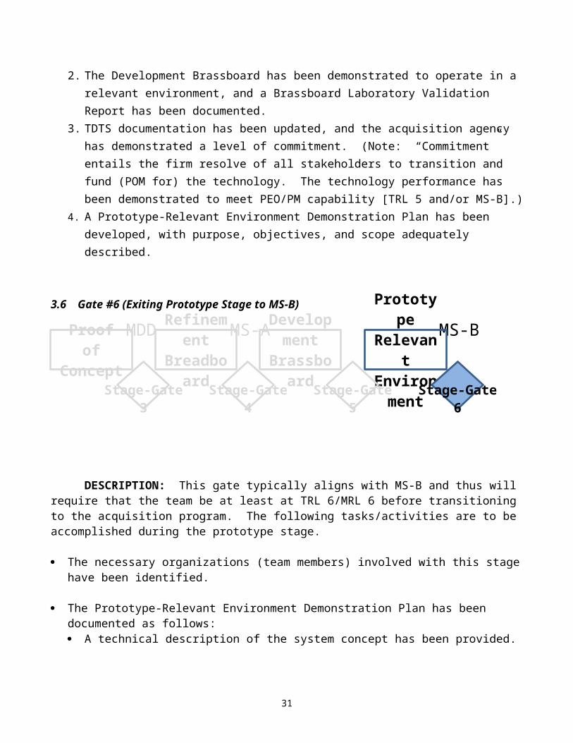
3.6 Gate #6 (Exiting Prototype Stage to MS-B)
DESCRIPTION: This gate typically aligns with MS-B and thus will require that the team be at least at TRL 6/MRL 6 before transitioning to the acquisition program. The following tasks/activities are to be accomplished during the prototype stage.
The necessary organizations (team members) involved with this stage have been identified.
The Prototype-Relevant Environment Demonstration Plan has been documented as follows: A technical description of the system concept has been provided.
The purpose described for validation testing was adequate and included test objectives, validated KPPs/KSAs, and a description of test configurations, within the defined relevant environment.
The final definition of “relevant environment” has been provided. The threats addressed by the technology, along with any potential future operational capabilities,
have been accurately documented. The test setup used for validation testing has been specified.
11 This can be satisfied by the application of the RI3 Guidebook methodology, or any other approved risk assessment tool.
22
Stage-Gate
Stage-Gate
Stage-Gate
Stage-Gate
Prototype Relevant
Environment
Development Brassboard
Refinement Breadboard
Proof of Concept
MS- MS-MD
Key technology system and subsystem items (hardware, software, algorithms) tested, as well as methods for threat representation, have been identified. Form, fit, and function parameters have been updated.
The testing environment has been sufficiently described, including instrumentation, special test equipment, and all external systems participating. A detailed test description including test schedule and location, organizations involved,
test results, outstanding issues, analyzed results of simulation, operational considerations, and technology constraints and limitations is available.
The criteria for each test have been provided. A description of each test (i.e., how it was conducted) has been provided. The technical results from the validation effort have been provided.
The methods for determining and assessing results based on content, quality, quantity, and completeness have been described, including all analyses performed, results documented, problems encountered. Data collected from the Prototype validation effort has been provided. Preliminary determinations of deficiencies, shortcomings, and suggested improvements
have been provided. A Performance Results Matrix has been populated and provided. Prototype validation conclusions have been provided. Recommendations from the Prototype validation effort have been developed and
provided. Risk assessment12 based on validation data and results has been updated. Results from the Prototype-Relevant Environment Review, Preliminary Design Review (if
conducted), or any other major reviews occurring during the Prototype validation effort have been provided.
Safety requirements applied during validation testing have been provided. Hazard identification and analysis results have been provided.
The TDTS documentation has been updated. Transition strategy has been integrated into LCMP or equivalent (for non-PoR), and a report is
available.
The CCTD has been updated.
The SEP has been updated, and a report is available.
PPP has been updated.
EXIT CRITERIA GATE #6:1. The technology prototype has been demonstrated to operate in a Prototype-Relevant (or
simulated operational) Environment.2. TRL 6; MRL per MRL plan.3. A Prototype-Relevant Environment Demonstration Report has been documented.
12 This can be satisfied by the application of the RI3 Guidebook methodology, or any other approved risk assessment tool.
23
4. Final TDTS documentation has been completed, and the transition strategy has been integrated into the LCMP.
24
4 Documenting the TDTS
4.1 TDTS Content OverviewThe TDTS is a living document that captures the early collaborative efforts of an IPT in (1)
assessing the current status (i.e., readiness level) of technology maturation, (2) identifying the desired/expected progress point for transitioning the technology to the acquisition program (i.e., readiness level and technology need/freeze date), and (3) determining whether the right thing is being done at the right time in order to successfully transition. Accordingly, with the intent of guiding teams through successful technology transition efforts, there exists a checklist of activities associated with each stage, as well as proposed exit criteria—based on the latest maturity readiness levels, systems engineering principles, and project management fundamentals—for each gate. These align with DoD 5000series instructions so that researchers and acquirers are speaking the same language.
The activities/items identified in the technology maturation checklists comprise the minimal information required for inclusion in the TDTS document. The IPT can incorporate additional, project-specific items as necessary. If any particular checklist item is deemed not applicable (N/A) to a given effort, the rationale behind the N/A decision must be documented.
The actual format for the strategy documentation can be tailored as required. Several iterations of the draft will likely be required within the IPT before all stakeholders are
satisfied with its content (the stage-gate process is designed to accommodate these iterations). It is important to record the activities, issues, agreements, and comments, as well as the disposition of issues and comments in order to avoid revisiting them during development and approval. Currently, this record can take the form of detailed meeting minutes or an IPT journal. As a result of the IPT’s collaborative effort, each version/amendment of the TDTS documentation will have the appropriate level of detail and emphasis. Accordingly, the approval authorities’ expectation will be that all relevant issues have been discussed and any alternative strategies have been explored during the documentation preparation. The final version of the TDTS document should focus on the best alternative for the technology maturation effort to transition to a follow-on acquisition program.
The TDTS document shall address the following items. This outline reflects the major headings required for the LCMP at MS-B (also applies to non-PoR efforts).
Program/Project Title Executive Summary Mission/Requirement Program Summary (Schedule/Roadmap/Exit Criteria for each gate) Program Management Business Strategy Program Risk Management Cost and Performance Management Early Systems Engineering (SE) and the life-cycle-based SE Approach Test Approach Product Support Concepts (-ilities)
The statements provided in each major heading area represent the key focus areas of that activity and are used to guide the IPT in developing a comprehensive transition strategy. Additional and detailed information about each major heading can be found in the references contained in Appendix 3. To the extent possible, the TDTS document should remain unclassified and free of any source-selection-
25
sensitive information. When necessary, classified or source-selection-sensitive information should be incorporated by reference.
4.1.1 Executive SummaryThe CER process, using the CCTD/AoA, will create the initial baseline for the TDTS document.
TDTS will enable the IPT to initiate development of the LCMP for MS-B throughout the initial phases of the project. The TDTS process will help meet the following:
Defining the capability need that this technology maturation effort is intended to meet Defining the decisions sought (initiation of the technology maturation effort, milestone
review, change to strategy, follow-on acquisition approval, and so on) Defining the exit criteria for this technology maturation effort to follow-on to an acquisition
program, including performance and physical attributes, minimum acceptable performance thresholds (if known), and an estimate of the TRL at the transition
Identifying the waivers, deviations, or certifications necessary for successful execution of the technology maturation effort, technology transition, and/or follow-on acquisition program. (Note: The detailed rationale for these waivers, deviations, or certifications included in this document must be discussed elsewhere in the appropriate section.)
Identifying the required approval/authorization levels
4.1.2 Mission/RequirementTDTS accomplished via the stage-gate process is designed to gather information needed for
keeping a project on track and meeting requirements. It does so by ensuring the following areas are addressed:
Identification of authoritative source documents (e.g., CCTD, AoA, Capabilities Review and Risk Assessment Tech Needs ID, ICD, Capability Development Document, Acquisition Program Baseline, Program Management Directive )
Definition of the expected capability that this technology will provide, if successful Identification of the user’s (or proposed) CONOPS and support concept Identification of the threat this system is expected to counter
o If the threat is not well-defined, defining the capabilities or operational concepts that this technology capability will support
o Identifying the key operational requirements envisioned for this system, and summarizing any time-phased capability requirements, if applicable
o Summarizing interoperability requirements for this system (to include appropriate International Standards Agreements)
o Describing how the technology efforts fit into the AF and/or joint CONOPS and current and future integrated architectures (AF and joint)
4.1.3 Program SummaryThe TDTS document captures technology maturation effort objectives derived from CER using a
stage-gate process that (1) identifies relevant issues; and (2) recommends both a transition, acquisition, and management approach and a support strategy, thereby serving as a roadmap for the life cycle of the technology effort (including its integration with the follow-on acquisition program). The stage-gate process will promote early and active involvement and collaboration among technology developers, acquisition program offices, and user representatives towards establishing a comprehensive strategy (specifically, TDTS) broken into smaller, more manageable stages. Adhering to this process is
26
fundamental to developing a timely and cost-effective transition strategy and will facilitate a more focused and substantiated POM submission. It will do so by ensuring the following areas are addressed:
Documenting the relevant history of this technology maturation effort and its receiving acquisition program (if acquisition program of record currently exists)
Describing the plan to acquire the initial technology (e.g., independent of future spirals, or first in a series of time-phased requirements), and describing the plan to acquire and complete any and all spirals.
Defining the current baseline of the technology maturation effort, to include TRL and MRL. Identifying any related technology maturation efforts, and identifying alternative solutions
considered (i.e., essentially, the results obtained from literature search/market research) Describing the technologies not addressed or delivered via this effort but that may be
involved in the weapon systems integration; and, as part of expectation management, describing what performance characteristics/capabilities will not be provided (but may be expected) by the technology maturation effort (Note: Typically, technologies not delivered via the technology maturation effort are activities that the transition agent and/or final recipient may want to address during the System Development and Demonstration phase of acquisition.)
Defining the exit criteria for each stage completion. Providing a summary description of the technology maturation effort requirements, which
shall include the following:o TRL/MRL roadmap, including cost, schedule, and funding sources for each stage of
the technology maturationo Definition of the limits required by the target acquisition office as related to risk
management 13
o Program milestones and schedule eventso Projected technology freeze date o Definition of “relevant environment” (i.e., the environment in which the technology
will operate) Providing estimated funding requirements and schedule for follow-on acquisition program
and schedule for POM insertion in order for seamless transition into follow-on program (including anticipated funding sources)
Providing an estimate of the total life-cycle costs associated with implementing this technology into the program in question
Identifying any concurrency among stages and other technology development and/or acquisition program(s)
Identifying whether this is a joint technology maturation effort and/or acquisition program Identifying the overall systems acquisition programs that are related to this program Providing an LCMP at Stage-Gate 6 (MS-B)
13 This can be satisfied by the application of the RI3 Guidebook methodology, or any other approved risk assessment tool.
27
4.1.4 Program ManagementOSD14 and GAO15 best practices direct the following activities: Identify the primary stakeholders and IPT members required at each stage. This team should
flow out of the CET that works CER activity. Define the roles and responsibilities for each IPT member at each stage (i.e., who manages
the what, how, and when of the technology’s transition into the follow-on acquisition program). (Note: The IPT chair and co-chair will identify how and when contractors will be brought into the team. It is highly encouraged to involve the contractor[s] in the IPT as early as possible.)
Systematically review the technology maturation effort to ensure that the program is on track for meeting the exit criteria at each stage. Include technical, manufacturing, affordability, and sustainment activities.
Identify how M&S has been integrated into the program planning activity. (Defense Acquisition Guidebook, paragraph 2.6.7 and AFI 16-1002, Modeling and Simulation (M&S) Support to Acquisition).
Identify the resources required to execute the technology maturation effort, follow-on acquisition, and life-cycle support. Include a projected manning profile based upon the approach and program schedule, to include the number of government and contractor support personnel required.
Identify the financial reporting requirements for the program. Develop the funds management strategy.
o If contingent liabilities—such as award fee, special incentives, economic price adjustment, business base clauses, termination liability, and so on—are to be used, define the funding profiles and funding sources.
o Include in the funds management strategy contingency plans for significant budget changes and resulting programmatic impacts. If the budget change means that the funding for the program no longer matches program content, define the program workaround.
Identify the management information systems to be used. Describe the approach for continued technology surveillance. Describe/include the
communications plan identifying the program stakeholders and the flow of information.
4.1.5 Business StrategyAddress the main acquisition approach, to include contract types, competition expected, source
selection procedures, provisions, sources, and product support considerations for the technology maturation effort. Describe how these business strategies will apply to the follow-acquisition program. When possible, establish a business strategy that provides the best cost and schedule benefit to the government (i.e., dual-sourcing tech development effort with down-select to follow-on program, obtain data rights, and so on). The requirements for an acquisition plan (reference FAR 7.105, as supplemented) should be used to help frame this area of the TDTS document.
Define the acquisition approach for the technology maturation effort program and the follow-on acquisition program (Procurement, 10 U.S.C. 2304, 10 U.S.C. 2305, and 10 U.S.C. 2306).
Describe partnering arrangements that are involved in the approach (e.g., partnering between labs, industry, program offices, other services).
14 OSD Transition Practical Operating Guidelines (TPOG). ibid.15 GAO-06-883 DoD Technology Transition, ibid.
28
Document the market research conducted, and describe the results (Procurement, 10 U.S.C. 2377).
Define the acquisition/contract strategy for technology maturation effort, as well as the follow-on acquisition efforts. Describe the features considered, such as competitive award, sole-source procurement, or dual-source development with down select to one acquisition development contract. Describe the strategy changes from the technology maturation effort to the follow-on acquisition programs. (Procurement, 10 U.S.C. 2304, 10 U.S.C. 2305, and 10 U.S.C. 2306, 15 U.S.C. 644 [a], [d], and [j]; PL 100-533)
o Define the source selection procedures to be utilized (AFFARS 5315.3, Procurement, 10 U.S.C. 2305).
o Identify the type of contract(s) anticipated (Procurement, 10 U.S.C. 2306).o Identify the anticipated contract incentives.o Identify any special contracting considerations.
If this is an award for a technology maturation effort for integration into a major system, describe the strategy for how the prime contractor will be involved to ensure seamless transition into the PoR.
Identify small business participation at both the direct award and subcontracting levels. Identify evolutionary technology maturation strategies and/or acquisition strategies that have
been incorporated (Air Force Evolutionary Acquisition Guide and AFI 63-123, Evolutionary Acquisition for Command and Control Systems).
Describe the plan to acquire the initial technology (e.g., independent of future spirals, first in a series of time-phased requirements). Describe the plan to acquire and complete all spirals.
4.1.6 Program Risk ManagementAfter accomplishing the initial Maturity Assessment, the IPT conducts an integrated risk
assessment of the technology maturation effort and the follow-on acquisition program. The results of this risk assessment help determine what activities need to be accomplished in order to meet the technology maturation effort’s exit criteria and help define the content of the program.
Describe the approach for identifying, analyzing, mitigating, tracking, and controlling performance, cost, and schedule risks.
Describe those risks that have been deferred to future technology maturation efforts and/or follow-on acquisition programs. Explain how these deferred risks will be eventually handled.
Describe the continued technical awareness efforts and interaction with stakeholders and key information sources (e.g., AFRL, industry), and highlight if—and how—risks have changed.
Identify key risk elements (AFMC Pamphlet 63-2, Acquisition Strategy Planning Process, and SAF/AQ Memo 95A-009).
Identify cost and schedule risks associated with these elements. Develop risk mitigation plans to eliminate or minimize risk. The following Risk
Management Tools are available in developing the risk mitigation approach: AFMC Pamphlet 63-101, Risk Management, and Risk Management Guide for DoD Acquisition 5000 Series.
4.1.7 Cost and Performance ManagementThe cost and performance management approach needs to summarize the estimate for the
technology maturation effort, initial and subsequent spirals; life-cycle cost estimate for follow-on
29
acquisition program, initial and subsequent increments; dependencies between increments accounted for in the estimates; and the estimating models used for core and subsequent increments. Note: The follow-on acquisition estimate will have less fidelity in the early stages, will be updated at each gate, and will be finalized in the LCMP prior to transition (Stage-Gate 6). Include a similar discussion for the technical performance estimates. Discuss how trade-offs between cost and performance will be encouraged and the government’s role in managing the trade space.
Define the technical and cost parameters that will be used to manage the technology maturation effort; include objective and threshold values.
Identify how trade-offs between cost and performance will be managed. Describe the technical approach for meeting the technology maturation effort’s performance
parameters. Describe the technical performance measures. Describe how Cost as an Independent Variable principles have been used to balance
projected costs with technical parameters. Define how the technology maturation effort will be managed to achieve these objectives (DoDD 5000.01 and DoDD 5000.02 and Defense Acquisition Guidebook).
Describe how the technology maturation effort program will address potential Reductions in Total Ownership Costs (AF RTOC Web site).
Describe the manufacturing and quality management systems and how they will contribute to minimizing cost, schedule, and performance risks throughout the product life cycle.
Define realistic estimates of costs for transition and technology integration into the follow-on acquisition.
o If any items cannot be estimated, so state and describe why. Identify when the estimates will be available.
o Describe the method used to update estimates (e.g., “x” months before each decision review or “x” months before beginning each increment).
4.1.8 Systems Engineering ApproachSE will be accomplished throughout the TDTS process and will create and update many reports
(i.e., CCTD, SEP, LCMP, and so on). Define the SE approach that will enable seamless transition to the follow-on acquisition
program, as follows: o Use SE as an approach for translating approved operational needs and requirements
into operationally suitable systems. The approach consists of a top-down iterative method, throughout the life cycle, of requirement analysis, functional analysis and allocation, design synthesis, and verification for ensuring maintainability, reliability, interoperability, and survivability.
o Develop a draft SEP at program initiation (CCTD), and continue SEP development as program progresses, to encompass SE requirements. The TDTS represents a significant portion of the technical content of the initial SEP and will update the SEP through Stage-Gates 3-6 (MS-B).
o The TTA/TTP is easily derived from the TDTS documentation.o Since a TDS is required at MS-A, the TDTS document is designed to satisfy all the
needs of a TDS.o MS-A will also start the draft LCMP. The stage-gate process was designed for
technology transition that starts with a MAJCOM customer pull and ends at MS-B,
30
and eventually the TDTS document will morph into the LCMP that will be approved at the appropriate organizational levels and at the appropriate point in the acquisition (usually by MS-B).
4.1.9 Test ApproachThe TDTS development process will be vetted by the IPT, with technology/capability life-cycle participants (and possibly operational test as well), as follows: Describe what type of testing is required to meet the objectives. Define the test approaches and the expectations of the tests.
o Conditions under which the technology will be tested/demonstrated prior to delivery to acquisition have been established and agreed to, including definition of relevant environment.
Draft Test Plan at program initiation, and generate updates as program progresses (10 U.S.C. 2366 and 10 U.S.C. 2400).
4.1.10 Product Support ConceptThe product support environment envisioned in the DoD 5000-series regulations (DoDD 5000.1,
DoDD 5000.2, and Defense Acquisition Guidebook) and by the AF includes the following attributes: End-user relationships that are based on performance outcomes (such as flying hours or the
mission availability of equipment) Integrated supply chains across government and industry that focus on system readiness and end-
user support and are responsive to the unique requirements of the military services Best-value providers selected from government, industry, or government/industry partnerships A support environment that maintains long-term competitive pressures on government and
industry providers Secure and integrated information systems across industry and government that enable
comprehensive supply chain integration and full asset visibility Continuous improvement of weapon system supportability and reduction in operating costs by
dedicated investments, as well as effective integration of weapon system support that is transparent to the end user and provides total combat logistics capability, as follows:
o Describing efforts during the technology maturation effort that address the previously noted product support attributes
o Identifying the sustainment officer in the acquisition organization responsible for identifying, resourcing, and executing sustainment post-transition
o Developing a realistic estimate of total life-cycle costso Developing the Product Support Concepts Plan that will describe at what point in the
technology maturation the following elements will be addressed: manpower, personnel maintenance, supportability, data management, supply, transportation, configuration management, and training
5 SummaryThe TDTS process develops a life-cycle strategy for maturation of a technology through the use
of a committed and motivated team of cross-functional individuals, with the primary goal to enable the transition of needed technologies into AF systems. This strategy places emphasis on transition at the earliest stages of technology maturation. When implemented properly, the AF stage-gate process will
31
improve technology transition efficiency and effectiveness by implementing specific exit criteria throughout the life cycle and will deliver tremendous benefits as it
enhances communication throughout the life-cycle of technology; implements a robust, repeatable process using the latest technology maturity readiness levels
and manufacturing readiness levels; incorporates SE principles and project management fundamentals; aligns technology maturation gates with the acquisition framework; affords informed decision making for the corporate investment strategy; increases return on investment, resulting in more on-time, on-cost transitions; and infuses situational awareness—which, in turn, enables better risk management.
32
6 Bibliography
1. DoD 5000 Defense Acquisition Guidebook.
2. Government Accountability Office (GAO) Review of Technology Transition Practices, presented at the 4th Annual Acquisition Research Symposium, May 2007.
3. GAO Report 99-162 – “Better Management of Technology Development Can Improve Weapon System Outcomes.”
4. GAO Report 05-480 – “Management Process Can Be Strengthened for New Technology Transition Programs.”
5. GAO Report 06-883 – “Stronger Practices Needed to Improve DoD Transition Processes.”
6. GAO Report 07-336 – “Major Construction Projects Need a Consistent Approach for Assessing Technology Readiness to Help Avoid Cost Increases and Delays.”
7. Inspector General Report D-2003-132 – “Air Force Transition of Advanced Technology Programs to Military Applications.”
8. Recommended Best Practice DAU [Defense Acquisition University] Technology Transition Center of Excellence, https://acc.dau.mil/CommunityBrowser.aspx?id=148163.
9. DoD Advanced Systems & Concepts Technology Transition Report to Congress – August 2007.
10. Project Management Journal Vol. 39, No. 1, 59-71, March 2008 FBI Report – “Best Project Management and Systems Engineering Practices in the Pre-acquisition Phase for Federal Intelligence and Defense Agencies.”
11. Stage-Gate, Inc., The Official Web Site of the Stage-Gate Product Innovation Process, http://www.stage-gate.com/index.php.
12. OSD Transition Practical Operating Guidelines (TPOG). DUSD (AS&C) in accordance with Under Secretary of Defense (Acquisition, Technology, and Logistics) (USD [AT&L]) and Director, Defense Research and Engineering (DDR&E)
13. Risk Identification: Integration & Ilities (RI3) Guidebook, Version 1.2, 15 December 2008. Available by request from SAF/AQRE: [email protected] .
33
Appendix 1 – Technology Readiness Level Definitions
TRL Definition Description
1Basic Principles Observed and
ReportedLowest level of technology readiness. Scientific research begins translation to applied research and development. Examples might include paper studies of a technology's basic properties.
2Technology Concept and/or
Application FormulatedInvention begins. Once basic principles are observed, practical applications can be invented. The application is speculative and there is no proof or detailed analysis to support the assumption. Examples remain limited to paper studies.
3
Analytical and Experimental Critical Function and/or Characteristic Proof
of Concept
Active research and development is initiated. This includes analytical studies and laboratory studies to physically validate analytical predictions of separate elements of the technology. Examples include components that are not yet integrated or representative.
4Component and/or Breadboard
Validated in Laboratory Environment
Basic technological components are integrated to establish the feasibility that the pieces will work together. This is relatively low fidelity compared to the eventual system. Examples include integration of ad hoc hardware in a laboratory.
5
Component and/or Breadboard Validated in Relevant Environment
Fidelity of breadboard technology increases significantly. The basic technological components are integrated with reasonably realistic supporting elements so that the technology can be tested in a simulated environment. Examples include high-fidelity laboratory integration of components.
6
System/Subsystem Model or Prototype Demonstrated in
Relevant Environment
Representative model or prototype system well beyond the breadboard tested for TRL 5 undergoes test in a relevant environment. Represents a major step in a technology's demonstrated readiness. Examples include prototype testing in a high-fidelity laboratory environment or simulated operational environment.
Appendix 1 – TRL Definitions

7
System Prototype Demonstrated in Operational Environment
Prototype near or at planned operational system. Represents a major advance from TRL 6 and requires demonstration of an actual system prototype in an operational environment (e.g., in an aircraft or other vehicle or in space). Examples include prototype testing in a test bed aircraft.
8
Actual System Completed and Flight-Qualified Through Test and
Demonstration
Technology has been proven to work in its final form and under expected conditions. In almost all cases, this TRL represents the end of true system development. Examples include developmental test and evaluation of the system in its intended weapon system to determine if it meets design specifications.
9
Actual System Flight-Proven Through Successful Mission
Operations
Actual application of the technology in its final form and under mission conditions, such as those encountered in operational test and evaluation. In almost all cases, this ends final debugging aspects of true system development. Examples include system usage under operational mission conditions.
Appendix 1 – TRL Definitions
Appendix 2 – Manufacturing Readiness Level Definitions
DoD Manufacturing Readiness Level Definitions Version 6.3- April 2, 2008(Source: www.dodmrl.com)
MRL Definition Description
1 Manufacturing Feasibility Assessed
Lowest level of manufacturing readiness. The focus is on top-level assessment of feasibility and manufacturing shortfalls. Basic manufacturing principles are defined and observed. Basic research, in the form of studies (i.e., 6.1 funds), begins to identify producibility and material solutions.
2 Manufacturing Concepts Defined
Characterized by the development of new manufacturing approaches or capabilities. Applied research translates basic research into solutions for broadly defined military needs. Demonstrations for validating feasible production of a prototype product/component commence with very little data available. Level typically constitutes applied research (i.e., 6.2) in the science and technology (S&T) environment and includes identification and study of material and process approaches, including M&S.
3 Manufacturing Concepts Developed
Marks the first real demonstrations of manufacturing concepts. Level is typical of technologies in S&T funding categories 6.2 and 6.3, wherein identification of current manufacturing concepts or producibility has occurred and is based on laboratory studies. Materials have been characterized for manufacturability and availability but require further evaluation and demonstration. Models that may possess limited functionality have been developed in a lab environment.
4Capability to Produce the
Technology in a Laboratory Environment
Required investments, such as manufacturing technology development identified. Processes ensuring manufacturability, producibility, and quality are in place and sufficient for producing technology demonstrators. Manufacturing risks for prototype build identified. Manufacturing cost drivers identified. Producibility assessments of design concepts completed. KPPs identified. Special needs for tooling, facilities, material handling and skills identified.
5Capability to Produce
Prototype Components in a Production-Relevant
Environment
Manufacturing strategy refined and integrated with Risk Management Plan. Enabling/critical technologies and components identified. Prototype materials, tooling and test equipment, and personnel skills demonstrated on components in a production-relevant environment, but many manufacturing processes and procedures remain in development. Manufacturing technology development efforts initiated or ongoing. Producibility assessments of key technologies and components ongoing. Cost model based upon detailed end-to-end value stream map.
Appendix 2 – MRL Definitions
6
Capability to Produce a Prototype System or
Subsystem in a Production-Relevant
Environment
Initial manufacturing approach developed. Majority of manufacturing processes defined and characterized, but significant engineering/design changes remain. Preliminary design of critical components completed. Producibility assessments of key technologies completed. Prototype materials, tooling and test equipment, and personnel skills demonstrated on subsystems/ systems in a production-relevant environment. Detailed cost analysis includes design trades. Cost targets allocated. Producibility considerations shape system development plans. Long-lead and key supply chain elements identified. Industrial Capabilities Assessment (ICA) for MS-B completed.
7
Capability to Produce Systems, Subsystems, or
Components in a Production-
Representative Environment
Detailed design under way. Material specifications approved. Materials available to meet planned pilot line build schedule. Manufacturing processes and procedures demonstrated in a production-representative environment. Detailed producibility trade studies and risk assessments under way. Cost models updated with detailed designs, rolled up to system level, and tracked against targets. Unit cost reduction efforts under way. Supply chain and supplier quality-assurance-assessed. Long-lead procurement plans in place. Production tooling and test equipment design and development initiated.
8Pilot Line Capability
DemonstratedReady to Begin Low-Rate
Production
Detailed system design essentially complete and sufficiently stable to enter low-rate production. All materials available to meet planned low-rate production schedule. Manufacturing and quality processes and procedures proven in a pilot line environment, under control, and ready for low-rate production. Known producibility risks pose no significant risk for low-rate production. Engineering cost model driven by detailed design and validated. Supply chain established and stable. ICA for MS-C completed.
9
Low-Rate Production Demonstrated
Capability in Place to Begin Full-Rate
Production
Major system design features stable and proven in test and evaluation. Materials available to meet planned rate production schedules. Manufacturing processes and procedures established and controlled to three-sigma or other appropriate quality level to meet key design characteristic tolerances in a low-rate production environment. Production risk monitoring ongoing. Low-rate production cost goals met and learning curve validated. Actual cost model developed for full-rate production (FRP) environment, including impact of continuous improvement.
10Full-Rate Production
DemonstratedLean Production Practices
in Place
Highest level of production readiness. Engineering/design changes are few and generally limited to quality and cost improvements. System, components, or items are in full-rate production and meet all engineering, performance, quality, and reliability requirements. All materials, manufacturing processes and procedures, and inspection and test equipment are in production and controlled to six-sigma or other appropriate quality level. FRP unit cost meets goal, and funding is sufficient for production at required rates. Lean practices are well-established, and continuous process improvements are ongoing.
Appendix 2 – MRL Definitions
Appendix 3 – Glossary
Acquisition Manager: Manages defense acquisition programs covering every aspect of acquisition, including engineering integration, program control, test and deployment, configuration management, production and manufacturing, quality assurance, and logistics support. Performs functions essential to acquisition programs involving major defense acquisition programs and other than major systems or subsystems. Performs acquisition support roles.
Development Brassboard: An experimental device (or a group of devices) used to determine feasibility and to develop technical and operational data. It normally will be a model sufficiently hardened for use outside of laboratory environments to demonstrate the technical and operational principles of immediate interest. It may resemble the end item but is not intended for use as the end item. Successful completion of this product will place the product at Technology Readiness Level 5.
Fielding: Insertion of a technology into a new or existing program that yields increased capability. This technology insertion has not been planned for and comes without adequate funding to be sustained through its life cycle. The end user has been shown the technology and believes the increased utility is beneficial; however, the addition has not been fully integrated into operational functions and may or may not be identified in any Concept of Operations or strategy (tactics, training, and procedures).
Operational Environment: Environment that addresses all operational requirements and specifications of the final system to include platform/packaging, as follows:
Operational Environment: The environment in which the final product will be operated. In the case of spaceflight hardware/software, this environment is space. In the case of ground-based or airborne systems that are not directed toward spaceflight, this environment is defined by the scope of operations. For software, this environment is defined by the operational platform and software operating system.Simulated Operational Environment: Either (1) a real environment that can simulate all operational requirements and specifications of the final system, or (2) a simulated environment that accommodates testing of a virtual prototype. Used in either case to determine whether a developmental system meets the operational requirements and specifications of the final system.
Proof of Concept: Analytical and experimental demonstration of hardware/software concepts that may or may not be incorporated into subsequent development and/or operational units.
Program Executive Officer (PEO): An individual in the AF acquisition process responsible for a specific program, or for an entire portfolio of similar programs.
Program Manager: Manages defense acquisition programs covering every aspect of acquisition, including engineering integration, program control, test and deployment, configuration management, production and manufacturing, quality assurance, and logistics support. Performs functions essential to acquisition programs involving major defense acquisition programs and other than major systems or subsystems. Performs acquisition support roles.
Prototype: A physical or virtual model used to evaluate the technical or manufacturing feasibility or military utility of a particular technology or process, concept, end item, or system.
Relevant Environment: Not all systems, subsystems, and/or components need to be operated in the operational environment in order to satisfactorily address performance margin requirements. Consequently, the relevant
Appendix 3 – Glossary
environment is the specific subset of the operational environment needed for demonstrating critical “at risk” aspects of final product performance in an operational environment.
Refinement Breadboard: Integrated components that provide a representation of a system/subsystem and that can be used to determine concept feasibility and to develop technical data. Typically configured for laboratory use in order to demonstrate the technical principles of immediate interest. May resemble final system/subsystem in function only. A low-fidelity unit that demonstrates function only, without respect to form or fit (in the case of hardware) or platform (in the case of software). It often uses commercial and/or ad hoc components and is not intended to provide definitive information regarding operational performance. Successful completion of this product will place the product at Technology Readiness Level 4.
Gate: A decision point in the development process where the given item or technology must pass predetermined criteria before beginning the next stage of development. This is a point at which go/no-go decisions could be made. Additionally, this is a point where the direction and level of work may undergo adjustment to ensure the final product or service will adequately meet ultimate MAJCOM customer needs.
Stage: Period wherein the action occurs; comprises all activities (tasks) needed to reach stage.
Stakeholder: Organization or individual having a vested interest in the outcome of the technology development and transition. May also be referenced as the sponsor.
Sustainment: Identification, planning, and budgeting for the full cost of a program, item, technology, or capability. This must include all costs for development, training, integration, maintenance, employment, and eventual disposal.
Technology Executive Officer: Commander of the Air Force Research Laboratory.
Technology Manager: Individual responsible for the development of a specific technology project. Science and technology manager, researcher, or technologist may all be referenced as the technology manager.
Transition: Insertion of a technology into a new or existing program that yields increased capability. This technology insertion has been planned for and comes with adequate funding to be sustained throughout its life cycle.
Appendix 3 – Glossary
Appendix 4 – Acronyms
AoA Analysis of AlternativesAFAE Air Force Acquisition Executive ALC Air Logistics CenterAPB Acquisition Program BaselineAT&L Acquisition Technology and Logistics
CAIV Cost as an Independent VariableCCTD Concept Characterization and Technical DescriptionCDD Capability Development DocumentCER Concept Exploration and RefinementCONOPS Concept of OperationsCRRA Capabilities Review and Risk Assessment
DAU Defense Acquisition UniversityDoD Department of Defense
FRP Full-Rate Production
GAO Government Accounting Office
ICA Industrial Capabilities AssessmentICD Initial Capabilities DocumentID IdentificationIPT Integrated Product Team
KPP Key Performance ParametersKSA Key System Attributes
LCCE Life-Cycle Cost EstimateLCMP Life-Cycle Management PlanLRIP Low-Rate Initial Production
M&S Modeling and SimulationMAJCOM Major CommandMDA Milestone Decision AuthorityMDD Materiel Development DecisionMRL Manufacturing Readiness LevelMS Milestone
NDAA National Defense Authorization Act
OSD Office of the Secretary of Defense
Appendix 4 - Acronyms
OUSD Office of the Under Secretary of Defense
PoR Program of RecordPEO Program Executive Officer PM Program Manager / Program ManagementPMD Program Management DirectivePOM Program Objective Memorandum
RFP Request for Proposal
S&T Science and TechnologySE Systems EngineeringSEP Systems Engineering Plan
TDS Technology Development Strategy TEO Technology Executive Officer TM Technology Manager / Technology ManagementTDTS Technology Development and Transition StrategyTPOG Transition Protected Operating GuidelinesTPMM Technology Program Management ModelTRA Technology Readiness AssessmentTRL Technology Readiness LevelTTA Technology Transition AgreementTTP Technology Transition Plan
USAF United States Air Force
Appendix 4 - Acronyms
Appendix 5 – Web Sites
Statutes & Law10 U.S.C. 139 (OT&E)10 U.S.C. 2304 (Procurement)10 U.S.C. 2305 (Procurement)10 U.S.C. 2306 (Procurement)10 U.S.C. 2350a (Cooperative Research and Development Agreements)10 U.S.C. 2366 (Testing)10 U.S.C. 2377 (Procurement)10 U.S.C. 2399 (OT&E)10 U.S.C. 2400 (TEMP)10 U.S.C. 2431 (MDAPs)10 U.S.C. 2435 (Acquisition Program Baseline)10 U.S.C. 2440 (Technology and Industrial Base Plans)10 U.S.C. 2464 (Core Logistics Capabilities)15 U.S.C. 644 (a), (d), and (j) (Small Business)42 U.S.C. 4321-4347 (National Environmental Policy)Clinger-Cohen Act of 1996Information Technology Management Reform ActNational Environmental Policy Act (NEPA) PL 100-533
DoD PublicationsDoDD 5000.1, The Defense Acquisition SystemDoDD 5000.2 Operation of the Defense Acquisition SystemDefense Acquisition Guidebook (formerly DoD 5000.2-R) http://acc.dau.mil/simplify/ev.php?ID=58394_201&ID2=DO_TOPIC
Air Force Publications
AFPD 61-1, Management of Scientific and Technical InformationAFI 61-101, Applied Technology CouncilAFMCI 61-102, Advanced Technology Demonstration Technology Transition PlanningDraft AFMCI 61-103, Management of Science and Technology (S&T)AFI 16-402, Aerospace Vehicle Programming, Assignment, Distribution, Accounting, and Termination AFI 16-1002, Modeling and Simulation (M&S) Support to AcquisitionAFPD 63-1, Capability-Based Acquisition SystemAFI 63-101, Acquisition System AFI 63-107, Integrated Product Support Planning and Assessment AFI 63-111, Contract Support for Systems and EquipmentAFI 63-123, Evolutionary Acquisition for Command and Control Systems AFI 65-501, Economic AnalysisAFI 99-103, Capabilities-Based Test and EvaluationAFMC Pamphlet 63-2, Acquisition Strategy Planning ProcessAFMC Pamphlet 63-101, Risk Management
Appendix 5 – Web Sites
Federal Acquisition RegulationFAR Part 6, Competition RequirementsFAR Part 7, Acquisition Planning (AFFARS Part 5307)
AFFARS Library - Part 5307, Acquisition PlanningFAR Part 15, Contracting by Negotiation
AFFARS 5315.3, Source SelectionFAR Part 39, Acquisition of Information TechnologyFAR 46.7, Warranties
GuidanceOSD's Rules of the Road, A Guide for Leading Successful Integrated Product TeamsRisk Management Guide for DoD AcquisitionAir Force Evolutionary Acquisition Guide (Draft)SAF/AQXA Policy and Guidance Business Case Analysis (DAU Community of Practice)SAF/FMBI New Start Homepage
Policy MemosOSD (AT&L) Memo, Selection of Contractors for Subsystems and Components, 12 July 2004Acting USD (AT&L) Memo, Performance-Based Logistics: Purchasing Using Performance-Based Criteria, 16 August 2004ASAF(A) and HQ USAF/IL memo, 14 June 1999SAF/AQ Memo 04A-001SAF/AQ Memo 03A-005SAF/AQ Memo 95A-009NEPA of 1969 (addresses ESOH and updates to include reference to Natural Infrastructure) Natural Infrastructure and Encroachment Prevention Policy, 23 November 2004, SAF/IE
Appendix 5 – Web Sites
Recommended