Data sheet
Description
The DNP31 devcie allows the connection of the Universal Motor Controller UMC100.3 to a DeviceNet network.
DNP31.0
DeviceNet Interface
Technical description
- 2 -DNP31.0 Data sheet Issue: 09.2015
Please note the followingTarget group
This description is intended for the use of trained specialists in electrical installation and control and automation engi-neering, who are familiar with the applicable national standards.
Safety requirements
The responsible staff must ensure that the application or use of the products described satisfy all the requirements for safety, including all the relevant laws, regulations, guidelines and standards.
Using this Handbook
Symbols
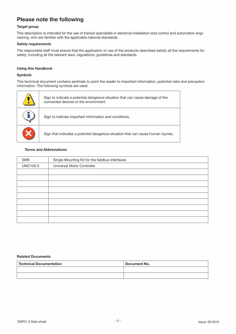
This technical document contains sentinels to point the reader to important information, potential risks and precaution information. The following symbols are used:
Sign to indicate a potential dangerous situation that can cause damage of the connected devices or the environment.
Sign to indicate important information and conditions.
Sign that indicates a potential dangerous situation that can cause human injuries.
Terms and Abbreviations
SMK Single Mounting Kit for the fieldbus interfaces
UMC100.3 Universal Motor Controller
Related Documents
Technical Documentation Document No.
- 3 - Data sheet DNP31.0Issue: 09.2015
Content
Overview ...................................................................................................................................................5
Mechanical Installation .............................................................................................................................6
Mounting the DNP31 on the UMC100.3 .............................................................................................6
Mounting the DNP31 remotely from the UMC100.3 ...........................................................................7
Demounting the DNP31 ......................................................................................................................8
Electrical installation .................................................................................................................................9
DeviceNet Connection ........................................................................................................................9
DeviceNet line with DNP31 directly connected to UMC100.3 in a drawout system ........................10
DeviceNet line with DNP31 mounted outside a drawer using single mounting kit (SMK3.0) ...........11
Diagnosis ................................................................................................................................................12
Diagnosis and behaviour in case of an error ....................................................................................12
Checklist ...........................................................................................................................................12
DeviceNet information about the properties of the DNP31 ....................................................................13
General information ..........................................................................................................................13
Class Code 001 (0x01): Identity Object ............................................................................................14
Class Code 002 (0x02): Message Router Object .............................................................................14
Class Code 004 (0x04): Assembly Object ........................................................................................15
Class Code 005 (0x05): Connection Object .....................................................................................16
Class Code 043 (0x2B): Acknowledge Handler Object ....................................................................19
Class Code 100 (0x64): ABB Discrete Input Object .........................................................................19
Class Code 101 (0x65): ABB Discrete Output Object ......................................................................20
Class Code 102 (0x66): ABB Analog Input Object ...........................................................................20
Class Code 103 (0x67): ABB Analog Output Object ........................................................................21
Class Code 105 (0x69): ABB Parameter Object ...............................................................................21
Class Code 112 (0x70): ABB Parameter Modular Object .................................................................22
Class Code 118 (0x76): ABB Any Data Class ...................................................................................22
Class Code 128 (0x80): ABB Query Object ......................................................................................22
Technical data ........................................................................................................................................23
Dimensions .............................................................................................................................................24
Connection Cables .................................................................................................................................24

- 4 -DNP31.0 Data sheet Issue: 09.2015
Document History
- 5 - Data sheet DNP31.0Issue: 09.2015
Overview
This chapter contains a short description of the DeviceNet standard and the DNP31 DeviceNet Interface module.
DeviceNet Standard
The DeviceNet network has a linear bus topology. Terminating resistors are required on each end of the trunk line. Drop lines as long as 6 metres (20 feet) each are permitted, allowing one or more nodes to be attached. DeviceNet allows branching structures only on drop lines.
The DeviceNet Communication Interface
The DNP31 communication interface is an optional device for the UMC100.3 which enables the connection of the UMC100.3 to a DeviceNet system. The UMC100.3 is considered as a slave in the DeviceNet network.
• Use UMC100.3 to set bus address and baud rate (or autobaud) of the DeviceNet communication. Once the address is set, it is stored in the DNP31, even in case of supply voltage breakdown.
Through the DNP31 DeviceNet communication interface it is possible to:
• give control commands to the drive (Start, Stop etc.)
• read status information and actual values from the drive
• read and write UMC100.3 parameter values
• reset a UMC100.3 trip.
The DNP31 acts as a Class 2 only slave with predefined master-slave connection set services. These include the Explicit Messaging, the Poll-Response service and the Change of State/Cyclic service. The DeviceNet commands and services supported by the DNP31 DeviceNet communication interface are discussed in chapter Communication.
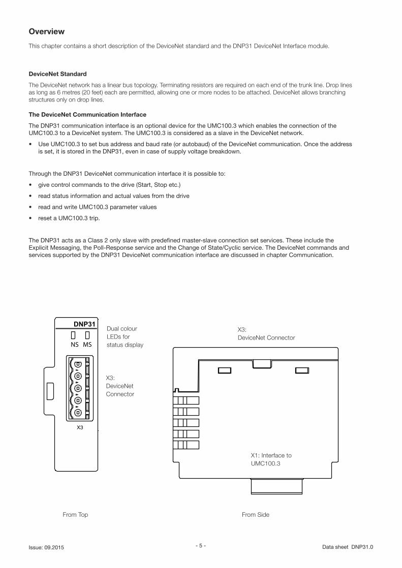
NS MS
DNP31
X3: DeviceNet Connector
Dual colour LEDs for status display
X3: DeviceNet Connector
From Top From Side
X1: Interface to UMC100.3
- 6 -DNP31.0 Data sheet Issue: 09.2015
Power
DNP31
NS MS
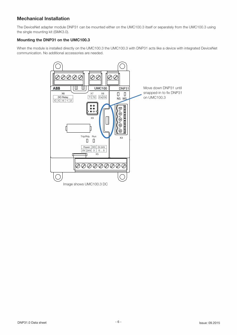
Mechanical Installation
The DeviceNet adapter module DNP31 can be mounted either on the UMC100.3 itself or separately from the UMC100.3 using the single mounting kit (SMK3.0).
Mounting the DNP31 on the UMC100.3
When the module is installed directly on the UMC100.3 the UMC100.3 with DNP31 acts like a device with integrated DeviceNet communication. No additional accessories are needed.
Move down DNP31 until snapped-in to fix DNP31 on UMC100.3
Image shows UMC100.3 DC
- 7 - Data sheet DNP31.0Issue: 09.2015
(1)
(2)
(2)
(1)
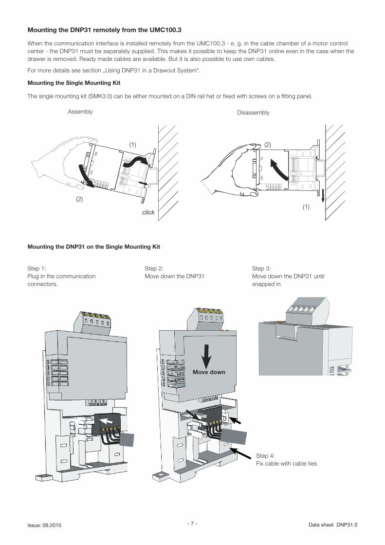
Mounting the DNP31 remotely from the UMC100.3
When the communication interface is installed remotely from the UMC100.3 - e. g. in the cable chamber of a motor control center - the DNP31 must be separately supplied. This makes it possible to keep the DNP31 online even in the case when the drawer is removed. Ready made cables are available. But it is also possible to use own cables.
For more details see section „Using DNP31 in a Drawout System“.
Mounting the Single Mounting Kit
The single mounting kit (SMK3.0) can be either mounted on a DIN rail hat or fixed with screws on a fitting panel.
Mounting the DNP31 on the Single Mounting Kit
Step 1: Plug in the communication connectors.
Step 3: Move down the DNP31 until snapped in
Step 2: Move down the DNP31
Move down
Step 4: Fix cable with cable ties
Assembly Disassembly
- 8 -DNP31.0 Data sheet Issue: 09.2015
DNP31
NS MS
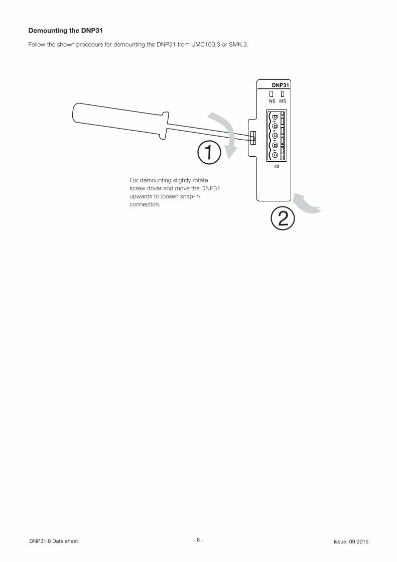
Demounting the DNP31
Follow the shown procedure for demounting the DNP31 from UMC100.3 or SMK.3.
For demounting slightly rotate screw driver and move the DNP31 upwards to loosen snap-in connection.
- 9 - Data sheet DNP31.0Issue: 09.2015
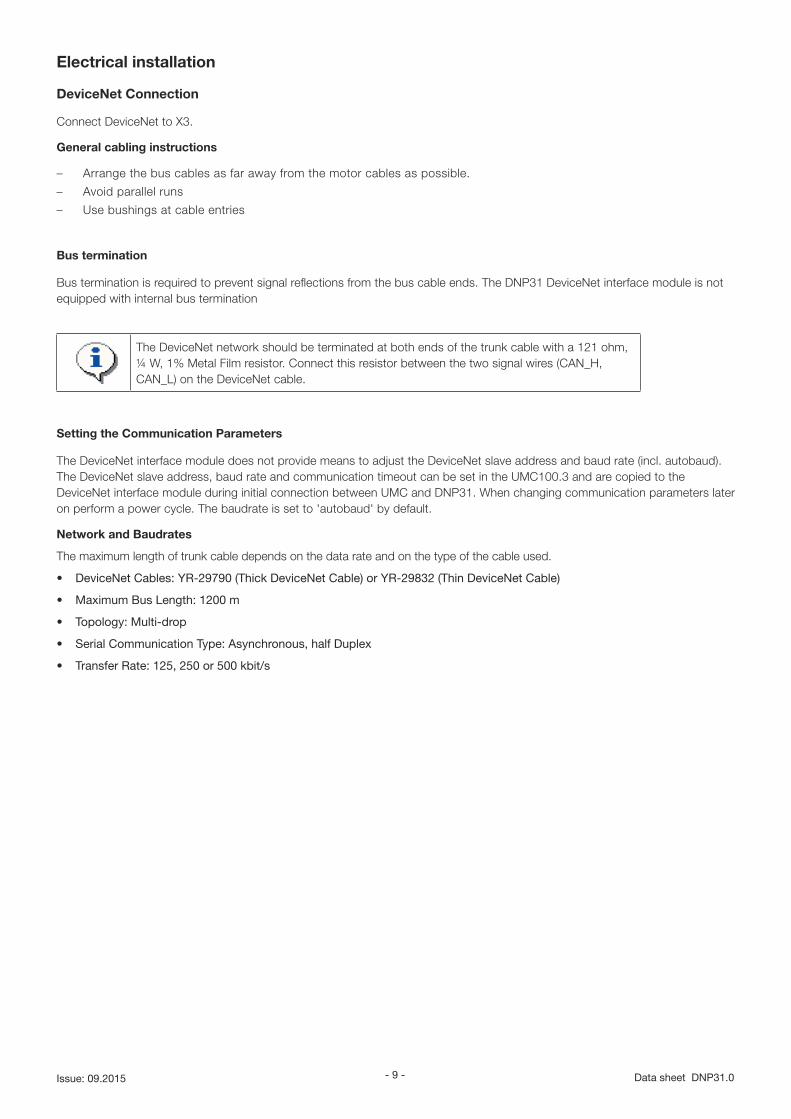
Electrical installation
DeviceNet Connection
Connect DeviceNet to X3.
General cabling instructions
– Arrange the bus cables as far away from the motor cables as possible.
– Avoid parallel runs
– Use bushings at cable entries
Bus termination
Bus termination is required to prevent signal reflections from the bus cable ends. The DNP31 DeviceNet interface module is not equipped with internal bus termination
The DeviceNet network should be terminated at both ends of the trunk cable with a 121 ohm, ¼ W, 1% Metal Film resistor. Connect this resistor between the two signal wires (CAN_H, CAN_L) on the DeviceNet cable.
Setting the Communication Parameters
The DeviceNet interface module does not provide means to adjust the DeviceNet slave address and baud rate (incl. autobaud). The DeviceNet slave address, baud rate and communication timeout can be set in the UMC100.3 and are copied to the DeviceNet interface module during initial connection between UMC and DNP31. When changing communication parameters later on perform a power cycle. The baudrate is set to 'autobaud' by default.
Network and Baudrates
The maximum length of trunk cable depends on the data rate and on the type of the cable used.
• DeviceNet Cables: YR-29790 (Thick DeviceNet Cable) or YR-29832 (Thin DeviceNet Cable)
• Maximum Bus Length: 1200 m
• Topology: Multi-drop
• Serial Communication Type: Asynchronous, half Duplex
• Transfer Rate: 125, 250 or 500 kbit/s
- 10 -DNP31.0 Data sheet Issue: 09.2015
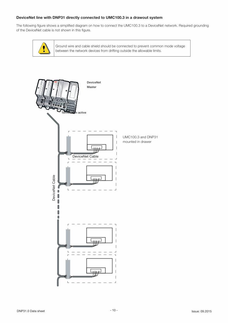
DeviceNet line with DNP31 directly connected to UMC100.3 in a drawout system
The following figure shows a simplified diagram on how to connect the UMC100.3 to a DeviceNet network. Required grounding of the DeviceNet cable is not shown in this figure.
UMC100.3 and DNP31 mounted in drawer
Termination active
Ground wire and cable shield should be connected to prevent common mode voltage between the network devices from drifting outside the allowable limits.
DeviceNet
Master
Dev
iceN
et C
able
DeviceNet Cable
- 11 - Data sheet DNP31.0Issue: 09.2015
X1
X1
(2)
(3)
(4)
max. 3m
(1)
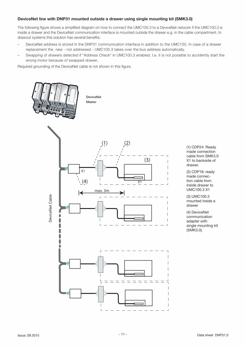
DeviceNet line with DNP31 mounted outside a drawer using single mounting kit (SMK3.0)
The following figure shows a simplified diagram on how to connect the UMC100.3 to a DeviceNet network if the UMC100.3 is inside a drawer and the DeviceNet communication interface is mounted outside the drawer e.g. in the cable compartment. In drawout systems this solution has several benefits:
– DeviceNet address is stored in the DNP31 communication interface in addition to the UMC100. In case of a drawer replacement the new - not addressed - UMC100.3 takes over the bus address automatically.
– Swapping of drawers detected if "Address Check" in UMC100.3 enabled. I.e. it is not possible to accidently start the wrong motor because of swapped drawer.
Required grounding of the DeviceNet cable is not shown in this figure.
DeviceNet
Master
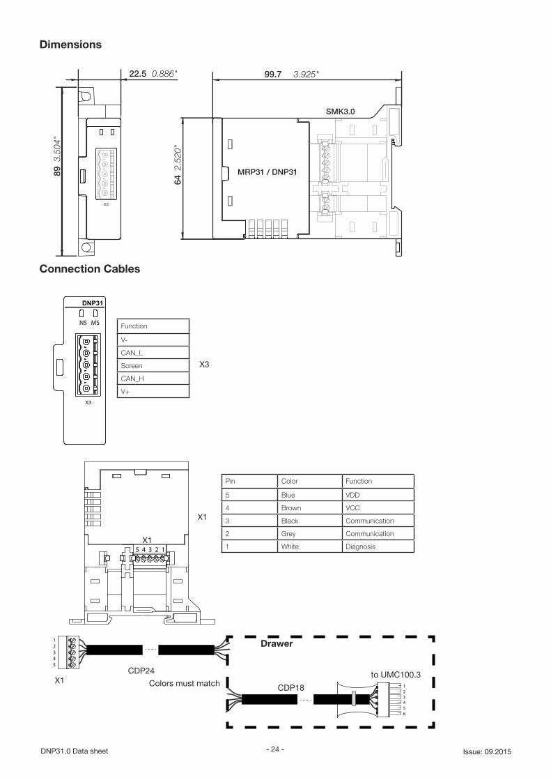
(1) CDP24: Ready made connection cable from SMK3.0 X1 to backside of drawer.
(2) CDP18: ready made connec-tion cable from inside drawer to UMC100.3 X1
(3) UMC100.3 mounted inside a drawer
(4) DeviceNet communication adapter with single mounting kit (SMK3.0).
Dev
iceN
et C
able
- 12 -DNP31.0 Data sheet Issue: 09.2015
Diagnosis
Diagnosis and behaviour in case of an error
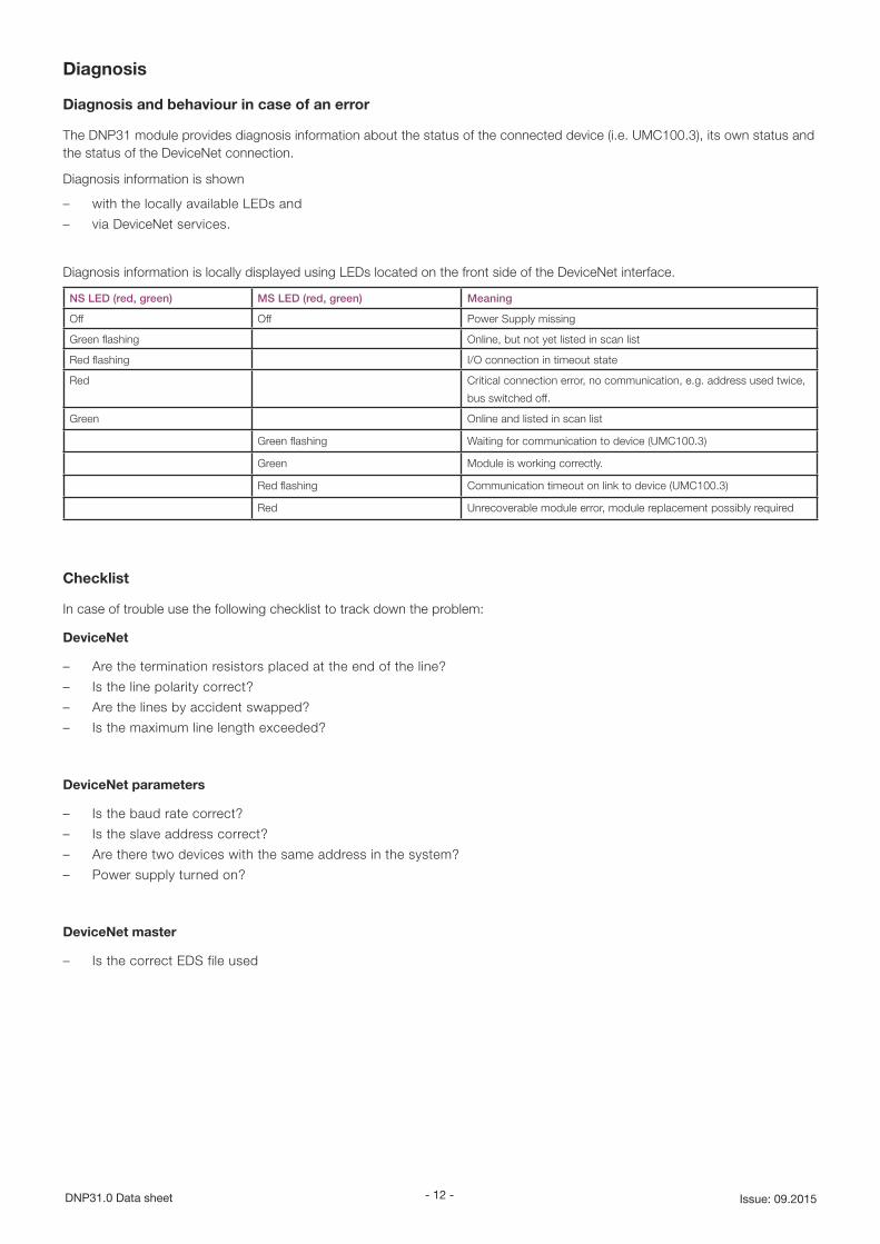
The DNP31 module provides diagnosis information about the status of the connected device (i.e. UMC100.3), its own status and the status of the DeviceNet connection.
Diagnosis information is shown
– with the locally available LEDs and
– via DeviceNet services.
Diagnosis information is locally displayed using LEDs located on the front side of the DeviceNet interface.
NS LED (red, green) MS LED (red, green) Meaning
Off Off Power Supply missing
Green flashing Online, but not yet listed in scan list
Red flashing I/O connection in timeout state
Red Critical connection error, no communication, e.g. address used twice,
bus switched off.
Green Online and listed in scan list
Green flashing Waiting for communication to device (UMC100.3)
Green Module is working correctly.
Red flashing Communication timeout on link to device (UMC100.3)
Red Unrecoverable module error, module replacement possibly required
Checklist
In case of trouble use the following checklist to track down the problem:
DeviceNet
– Are the termination resistors placed at the end of the line?
– Is the line polarity correct?
– Are the lines by accident swapped?
– Is the maximum line length exceeded?
DeviceNet parameters
– Is the baud rate correct?
– Is the slave address correct?
– Are there two devices with the same address in the system?
– Power supply turned on?
DeviceNet master
– Is the correct EDS file used
- 13 - Data sheet DNP31.0Issue: 09.2015
DeviceNet information about the properties of the DNP31
General information
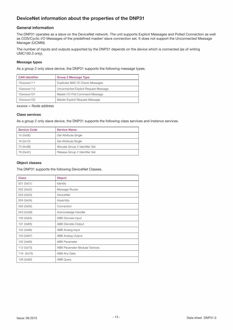
The DNP31 operates as a slave on the DeviceNet network. The unit supports Explicit Messages and Polled Connection as well as COS/Cyclic I/O Messages of the predefined master/ slave connection set. It does not support the Unconnected Message Manager (UCMM).
The number of inputs and outputs supported by the DNP31 depends on the device which is connected (as of writing UMC100.3 only).
Message types
As a group 2 only slave device, the DNP31 supports the following message types.
CAN Identifier Group 2 Message Type
10xxxxxx111 Duplicate MAC ID Check Messages
10xxxxxx110 Unconnected Explicit Request Message
10xxxxxx101 Master I/O Poll Command Message
10xxxxxx100 Master Explicit Request Message
xxxxxx = Node address
Class services
As a group 2 only slave device, the DNP31 supports the following class services and instance services.
Service Code Service Name
14 (0x0E) Get Attribute Single
16 (0x10) Set Attribute Single
75 (0x4B) Allocate Group 2 Identifier Set
76 (0x4C) Release Group 2 Identifier Set
Object classes
The DNP31 supports the following DeviceNet Classes.
Class Object
001 (0x01) Identity
002 (0x02) Message Router
003 (0x03) DeviceNet
004 (0x04) Assembly
005 (0x05) Connection
043 (0x2B) Acknowledge Handler
100 (0x64) ABB Discrete Input
101 (0x65) ABB Discrete Output
102 (0x66) ABB Analog Input
103 (0x67) ABB Analog Output
105 (0x69) ABB Parameter
112 (0x70) ABB Parameter Modular Devices
118 (0x76) ABB Any Data
128 (0x80) ABB Query
- 14 -DNP31.0 Data sheet Issue: 09.2015
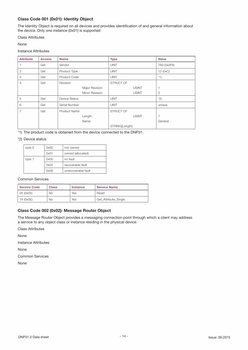
Class Code 001 (0x01): Identity Object
The Identity Object is required on all devices and provides identification of and general information about the device. Only one instance (0x01) is supported
Class Attributes
None
Instance Attributes
Attribute Access Name Type Value
1 Get Vendor UINT 760 (0x2F8)
2 Get Product Type UINT 12 (0xC)
3 Get Product Code UINT *1)
4 Get Revision
Major Revision
Minor Revision
STRUCT OF
USINT
USINT
1
3
5 Get Device Status UINT *2)
6 Get Serial Number UINT unique
7 Get Product Name
Length
Name
STRUCT OF
USINT
STRING[Length]
7
General
*1) The product code is obtained from the device connected to the DNP31.
*2) Device status
byte 0 0x00 not owned
0x01 owned (allocated)
byte 1 0x00 no fault
0x04 recoverable fault
0x08 unrecoverable fault
Common Services
Service Code Class Instance Service Name
05 (0x05) No Yes Reset
14 (0x0E) No Yes Get_Attribute_Single
Class Code 002 (0x02): Message Router Object
The Message Router Object provides a messaging connection point through which a client may address a service to any object class or instance residing in the physical device.
Class Attributes
None
Instance Attributes
None
Common Services
None
- 15 - Data sheet DNP31.0Issue: 09.2015
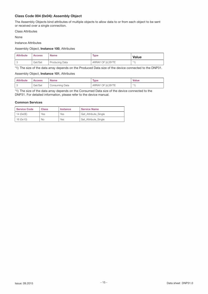
Class Code 004 (0x04): Assembly Object
The Assembly Objects bind attributes of multiple objects to allow data to or from each object to be sent or received over a single connection.
Class Attributes
None
Instance Attributes
Assembly Object, Instance 100, Attributes
Attribute Access Name Type Value3 Get/Set Producing Data ARRAY OF [n] BYTE *1)
*1) The size of the data array depends on the Produced Data size of the device connected to the DNP31.
Assembly Object, Instance 101, Attributes
Attribute Access Name Type Value
3 Get/Set Consuming Data ARRAY OF [n] BYTE *1)
*1) The size of the data array depends on the Consumed Data size of the device connected to the DNP31. For detailed information, please refer to the device manual.
Common Services
Service Code Class Instance Service Name
14 (0x0E) Yes Yes Get_Attribute_Single
16 (0x10) No Yes Set_Attribute_Single
- 16 -DNP31.0 Data sheet Issue: 09.2015
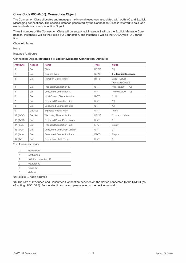
Class Code 005 (0x05): Connection Object
The Connection Class allocates and manages the internal resources associated with both I/O and Explicit Messaging connections. The specific instance generated by the Connection Class is referred to as a Con-nection Instance or a Connection Object.
Three instances of the Connection Class will be supported. Instance 1 will be the Explicit Message Con-nection, instance 2 will be the Polled I/O Connection, and instance 4 will be the COS/Cyclic IO Connec-tion.
Class Attributes
None
Instance Attributes
Connection Object, Instance 1 = Explicit Message Connection, Attributes
Attribute Access Name Type Value
1 Get State USINT *1)
2 Get Instance Type USINT 0 = Explicit Message
3 Get Transport Class Trigger BYTE 0x83 - Server,
Transport Class 3
4 Get Produced Connection ID UINT 10xxxxxx011 *2)
5 Get Consumed Connection ID UINT 10xxxxxx100 *2)
6 Get Initial Comm. Characteristics BYTE 0x21
7 Get Produced Connection Size UINT *3)
8 Get Consumed Connection Size UINT *3)
9 Get/Set Expected Packet Rate UINT in ms
12 (0x0C) Get/Set Watchdog Timeout Action USINT 01 = auto delete
13 (0x0D) Get Produced Conn. Path Length UINT 0
14 (0x0E) Get Produced Connection Path EPATH Empty
15 (0x0F) Get Consumed Conn. Path Length UINT 0
16 (0x10) Get Consumed Connection Path EPATH Empty
17 (0x11) Get Production Inhibit Time UINT 0
*1) Connection state
0 nonexistent
1 configuring
2 wait for connection ID
3 established
4 timed out
5 deferred
*2) xxxxxx = node address
*3) The size of Produced and Consumed Connection depends on the device connected to the DNP31 (as of writing UMC100.3). For detailed information, please refer to the device manual.
- 17 - Data sheet DNP31.0Issue: 09.2015
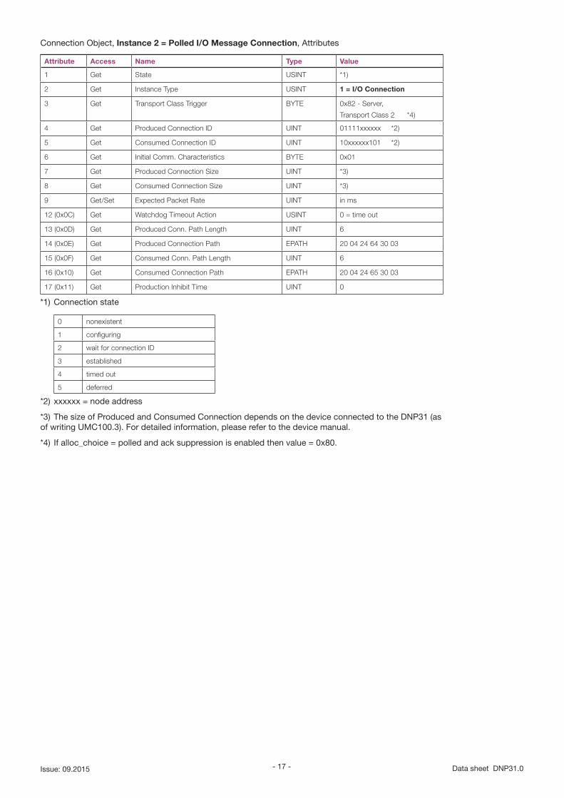
Connection Object, Instance 2 = Polled I/O Message Connection, Attributes
Attribute Access Name Type Value
1 Get State USINT *1)
2 Get Instance Type USINT 1 = I/O Connection
3 Get Transport Class Trigger BYTE 0x82 - Server,
Transport Class 2 *4)
4 Get Produced Connection ID UINT 01111xxxxxx *2)
5 Get Consumed Connection ID UINT 10xxxxxx101 *2)
6 Get Initial Comm. Characteristics BYTE 0x01
7 Get Produced Connection Size UINT *3)
8 Get Consumed Connection Size UINT *3)
9 Get/Set Expected Packet Rate UINT in ms
12 (0x0C) Get Watchdog Timeout Action USINT 0 = time out
13 (0x0D) Get Produced Conn. Path Length UINT 6
14 (0x0E) Get Produced Connection Path EPATH 20 04 24 64 30 03
15 (0x0F) Get Consumed Conn. Path Length UINT 6
16 (0x10) Get Consumed Connection Path EPATH 20 04 24 65 30 03
17 (0x11) Get Production Inhibit Time UINT 0
*1) Connection state
0 nonexistent
1 configuring
2 wait for connection ID
3 established
4 timed out
5 deferred
*2) xxxxxx = node address
*3) The size of Produced and Consumed Connection depends on the device connected to the DNP31 (as of writing UMC100.3). For detailed information, please refer to the device manual.
*4) If alloc_choice = polled and ack suppression is enabled then value = 0x80.
- 18 -DNP31.0 Data sheet Issue: 09.2015
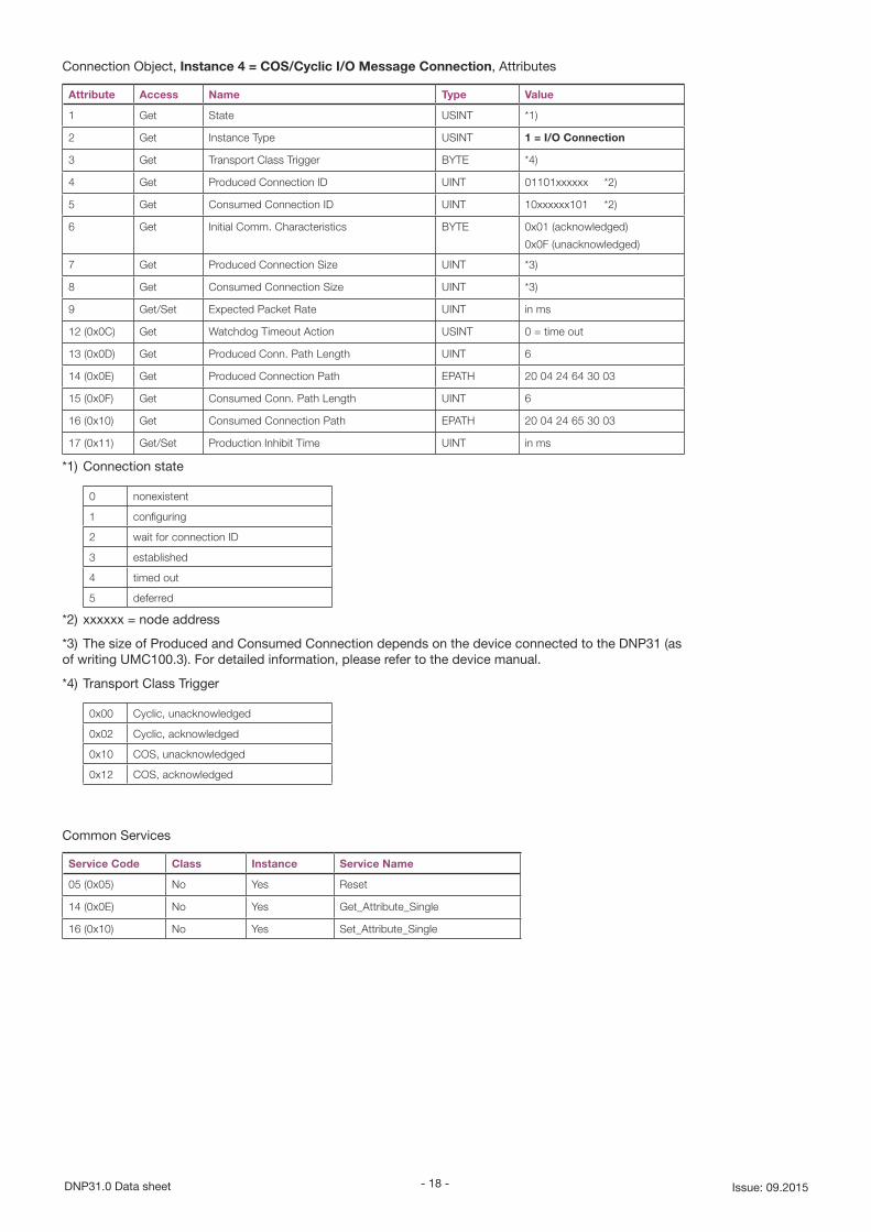
Connection Object, Instance 4 = COS/Cyclic I/O Message Connection, Attributes
Attribute Access Name Type Value
1 Get State USINT *1)
2 Get Instance Type USINT 1 = I/O Connection
3 Get Transport Class Trigger BYTE *4)
4 Get Produced Connection ID UINT 01101xxxxxx *2)
5 Get Consumed Connection ID UINT 10xxxxxx101 *2)
6 Get Initial Comm. Characteristics BYTE 0x01 (acknowledged)
0x0F (unacknowledged)
7 Get Produced Connection Size UINT *3)
8 Get Consumed Connection Size UINT *3)
9 Get/Set Expected Packet Rate UINT in ms
12 (0x0C) Get Watchdog Timeout Action USINT 0 = time out
13 (0x0D) Get Produced Conn. Path Length UINT 6
14 (0x0E) Get Produced Connection Path EPATH 20 04 24 64 30 03
15 (0x0F) Get Consumed Conn. Path Length UINT 6
16 (0x10) Get Consumed Connection Path EPATH 20 04 24 65 30 03
17 (0x11) Get/Set Production Inhibit Time UINT in ms
*1) Connection state
0 nonexistent
1 configuring
2 wait for connection ID
3 established
4 timed out
5 deferred
*2) xxxxxx = node address
*3) The size of Produced and Consumed Connection depends on the device connected to the DNP31 (as of writing UMC100.3). For detailed information, please refer to the device manual.
*4) Transport Class Trigger
0x00 Cyclic, unacknowledged
0x02 Cyclic, acknowledged
0x10 COS, unacknowledged
0x12 COS, acknowledged
Common Services
Service Code Class Instance Service Name
05 (0x05) No Yes Reset
14 (0x0E) No Yes Get_Attribute_Single
16 (0x10) No Yes Set_Attribute_Single
- 19 - Data sheet DNP31.0Issue: 09.2015
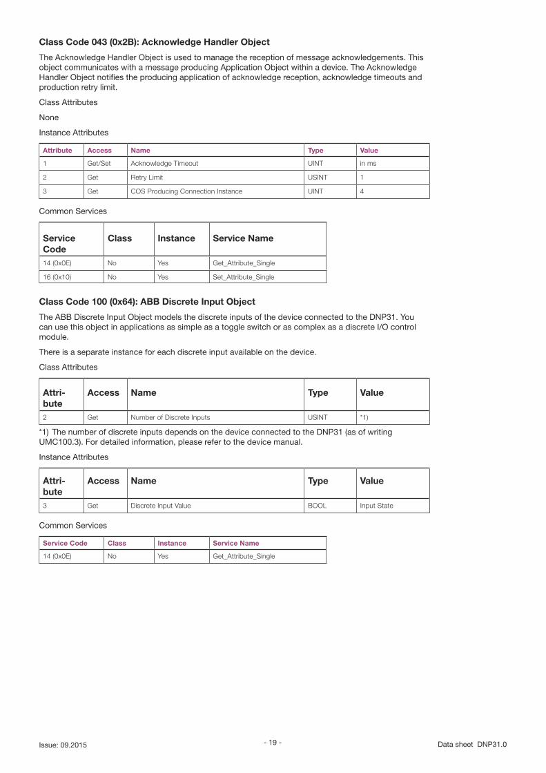
Class Code 043 (0x2B): Acknowledge Handler Object
The Acknowledge Handler Object is used to manage the reception of message acknowledgements. This object communicates with a message producing Application Object within a device. The Acknowledge Handler Object notifies the producing application of acknowledge reception, acknowledge timeouts and production retry limit.
Class Attributes
None
Instance Attributes
Attribute Access Name Type Value
1 Get/Set Acknowledge Timeout UINT in ms
2 Get Retry Limit USINT 1
3 Get COS Producing Connection Instance UINT 4
Common Services
Service Code
Class Instance Service Name
14 (0x0E) No Yes Get_Attribute_Single
16 (0x10) No Yes Set_Attribute_Single
Class Code 100 (0x64): ABB Discrete Input Object
The ABB Discrete Input Object models the discrete inputs of the device connected to the DNP31. You can use this object in applications as simple as a toggle switch or as complex as a discrete I/O control module.
There is a separate instance for each discrete input available on the device.
Class Attributes
Attri-bute
Access Name Type Value
2 Get Number of Discrete Inputs USINT *1)
*1) The number of discrete inputs depends on the device connected to the DNP31 (as of writing UMC100.3). For detailed information, please refer to the device manual.
Instance Attributes
Attri-bute
Access Name Type Value
3 Get Discrete Input Value BOOL Input State
Common Services
Service Code Class Instance Service Name
14 (0x0E) No Yes Get_Attribute_Single
- 20 -DNP31.0 Data sheet Issue: 09.2015
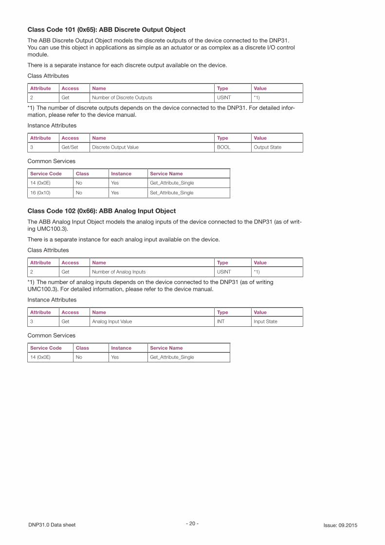
Class Code 101 (0x65): ABB Discrete Output Object
The ABB Discrete Output Object models the discrete outputs of the device connected to the DNP31. You can use this object in applications as simple as an actuator or as complex as a discrete I/O control module.
There is a separate instance for each discrete output available on the device.
Class Attributes
Attribute Access Name Type Value
2 Get Number of Discrete Outputs USINT *1)
*1) The number of discrete outputs depends on the device connected to the DNP31. For detailed infor-mation, please refer to the device manual.
Instance Attributes
Attribute Access Name Type Value
3 Get/Set Discrete Output Value BOOL Output State
Common Services
Service Code Class Instance Service Name
14 (0x0E) No Yes Get_Attribute_Single
16 (0x10) No Yes Set_Attribute_Single
Class Code 102 (0x66): ABB Analog Input Object
The ABB Analog Input Object models the analog inputs of the device connected to the DNP31 (as of writ-ing UMC100.3).
There is a separate instance for each analog input available on the device.
Class Attributes
Attribute Access Name Type Value
2 Get Number of Analog Inputs USINT *1)
*1) The number of analog inputs depends on the device connected to the DNP31 (as of writing UMC100.3). For detailed information, please refer to the device manual.
Instance Attributes
Attribute Access Name Type Value
3 Get Analog Input Value INT Input State
Common Services
Service Code Class Instance Service Name
14 (0x0E) No Yes Get_Attribute_Single
- 21 - Data sheet DNP31.0Issue: 09.2015
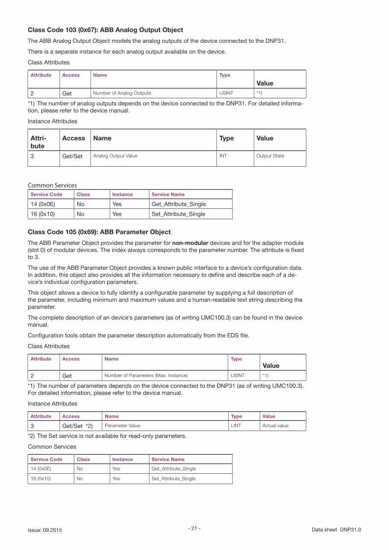
Class Code 103 (0x67): ABB Analog Output Object
The ABB Analog Output Object models the analog outputs of the device connected to the DNP31.
There is a separate instance for each analog output available on the device.
Class Attributes
Attribute Access Name Type
Value
2 Get Number of Analog Outputs USINT *1)
*1) The number of analog outputs depends on the device connected to the DNP31. For detailed informa-tion, please refer to the device manual.
Instance Attributes
Attri-bute
Access Name Type Value
3 Get/Set Analog Output Value INT Output State
Common ServicesService Code Class Instance Service Name
14 (0x0E) No Yes Get_Attribute_Single
16 (0x10) No Yes Set_Attribute_Single
Class Code 105 (0x69): ABB Parameter Object
The ABB Parameter Object provides the parameter for non-modular devices and for the adapter module (slot 0) of modular devices. The index always corresponds to the parameter number. The attribute is fixed to 3.
The use of the ABB Parameter Object provides a known public interface to a device’s configuration data. In addition, this object also provides all the information necessary to define and describe each of a de-vice’s individual configuration parameters.
This object allows a device to fully identify a configurable parameter by supplying a full description of the parameter, including minimum and maximum values and a human-readable text string describing the parameter.
The complete description of an device’s parameters (as of writing UMC100.3) can be found in the device manual.
Configuration tools obtain the parameter description automatically from the EDS file.
Class Attributes
Attribute Access Name Type
Value
2 Get Number of Parameters (Max. Instance) USINT *1)
*1) The number of parameters depends on the device connected to the DNP31 (as of writing UMC100.3). For detailed information, please refer to the device manual.
Instance Attributes
Attribute Access Name Type Value
3 Get/Set *2) Parameter Value LINT Actual value
*2) The Set service is not available for read-only parameters.
Common Services
Service Code Class Instance Service Name
14 (0x0E) No Yes Get_Attribute_Single
16 (0x10) No Yes Set_Attribute_Single
- 22 -DNP31.0 Data sheet Issue: 09.2015
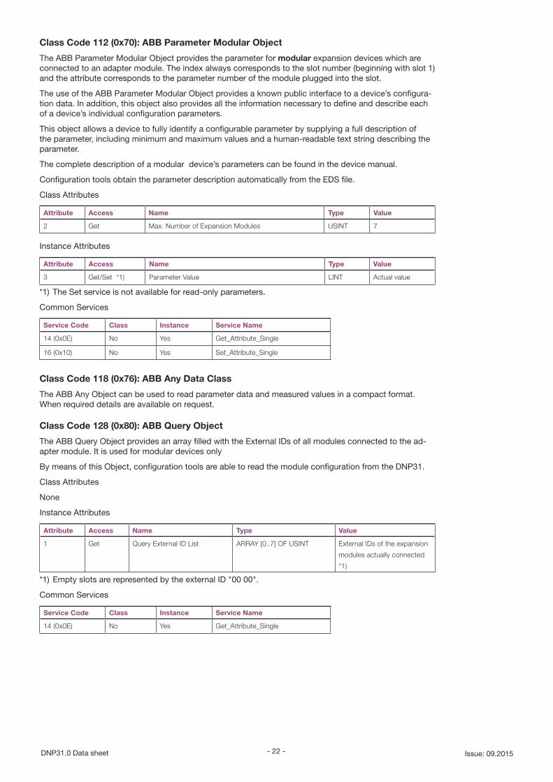
Class Code 112 (0x70): ABB Parameter Modular Object
The ABB Parameter Modular Object provides the parameter for modular expansion devices which are connected to an adapter module. The index always corresponds to the slot number (beginning with slot 1) and the attribute corresponds to the parameter number of the module plugged into the slot.
The use of the ABB Parameter Modular Object provides a known public interface to a device’s configura-tion data. In addition, this object also provides all the information necessary to define and describe each of a device’s individual configuration parameters.
This object allows a device to fully identify a configurable parameter by supplying a full description of the parameter, including minimum and maximum values and a human-readable text string describing the parameter.
The complete description of a modular device’s parameters can be found in the device manual.
Configuration tools obtain the parameter description automatically from the EDS file.
Class Attributes
Attribute Access Name Type Value
2 Get Max. Number of Expansion Modules USINT 7
Instance Attributes
Attribute Access Name Type Value
3 Get/Set *1) Parameter Value LINT Actual value
*1) The Set service is not available for read-only parameters.
Common Services
Service Code Class Instance Service Name
14 (0x0E) No Yes Get_Attribute_Single
16 (0x10) No Yes Set_Attribute_Single
Class Code 118 (0x76): ABB Any Data Class
The ABB Any Object can be used to read parameter data and measured values in a compact format. When required details are available on request.
Class Code 128 (0x80): ABB Query Object
The ABB Query Object provides an array filled with the External IDs of all modules connected to the ad-apter module. It is used for modular devices only
By means of this Object, configuration tools are able to read the module configuration from the DNP31.
Class Attributes
None
Instance Attributes
Attribute Access Name Type Value
1 Get Query External ID List ARRAY [0..7] OF USINT External IDs of the expansion
modules actually connected
*1)
*1) Empty slots are represented by the external ID "00 00".
Common Services
Service Code Class Instance Service Name
14 (0x0E) No Yes Get_Attribute_Single
- 23 - Data sheet DNP31.0Issue: 09.2015
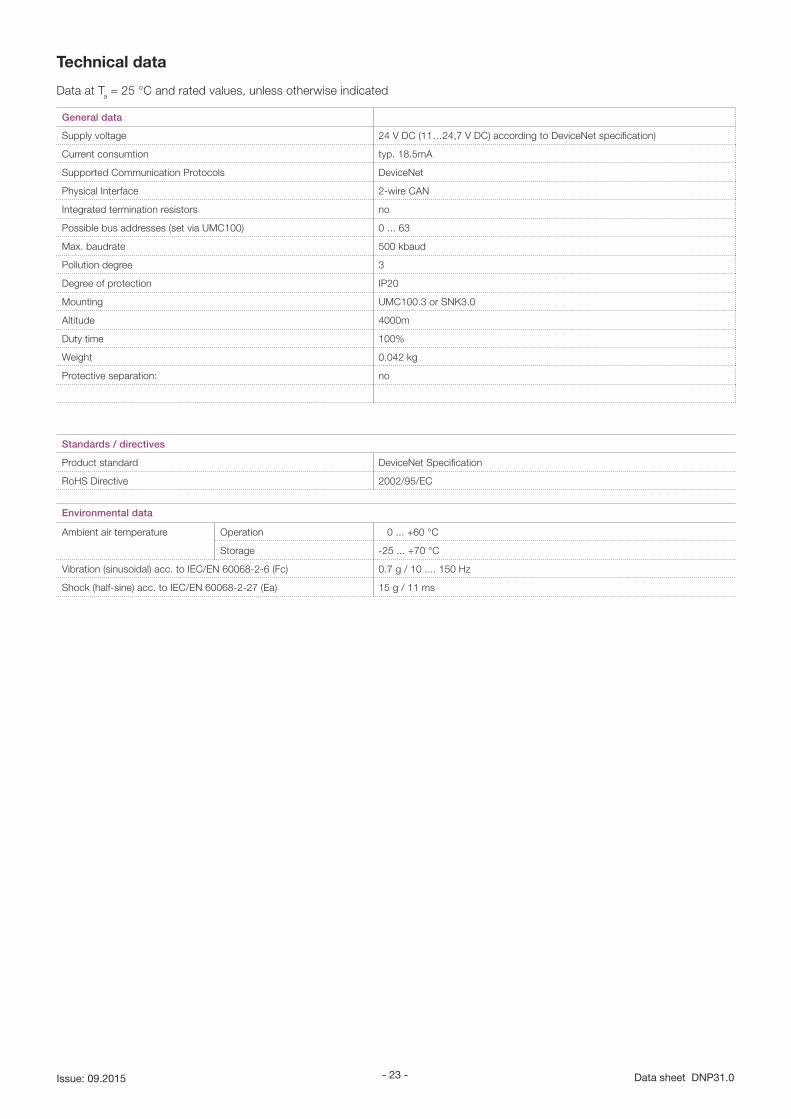
Technical data
Data at Ta = 25 °C and rated values, unless otherwise indicated
General data
Supply voltage 24 V DC (11…24,7 V DC) according to DeviceNet specification)
Current consumtion typ. 18.5mA
Supported Communication Protocols DeviceNet
Physical Interface 2-wire CAN
Integrated termination resistors no
Possible bus addresses (set via UMC100) 0 ... 63
Max. baudrate 500 kbaud
Pollution degree 3
Degree of protection IP20
Mounting UMC100.3 or SNK3.0
Altitude 4000m
Duty time 100%
Weight 0.042 kg
Protective separation: no
Standards / directives
Product standard DeviceNet Specification
RoHS Directive 2002/95/EC
Environmental data
Ambient air temperature Operation 0 ... +60 °C
Storage -25 ... +70 °C
Vibration (sinusoidal) acc. to IEC/EN 60068-2-6 (Fc) 0.7 g / 10 .... 150 Hz
Shock (half-sine) acc. to IEC/EN 60068-2-27 (Ea) 15 g / 11 ms
- 24 -DNP31.0 Data sheet Issue: 09.2015
SMK3.0
MRP31 / DNP31
22.5
89
64
99.7 0.886"
3.50
4"
2.52
0"
3.925"
5 4 3 2 1
12345
123456
CDP18
CDP24
X1
X1
X1
Dimensions
Connection Cables
Pin Color Function
5 Blue VDD
4 Brown VCC
3 Black Communication
2 Grey Communication
1 White Diagnosis
Colors must match
Drawer
to UMC100.3
NS MS
DNP31
Function
V-
CAN_L
Screen
CAN_H
V+
X3
- 25 - Data sheet DNP31.0Issue: 09.2015
Dokument-Nr.: 2CDC193005D0201
Detected an Error?Your feedback helps us to constantly improve our products. We are grateful for your comments and sug-gestions. Please provide us with the following information if you have noticed an issue:
Name
Company / Department
Telephone / Email
Problem Description
• Steps to reproduce the problem
• Version of UMC (Ident number on nameplate and firmware version which is displayed on the UMC100-PAN)
• Version of MRP (Ident number on nameplate)
FAX No.: +49 (0) 6221-701-1382

MEMO
- 26 -DNP31.0 Data sheet Issue: 09.2015

2C
DC
1930
05D
0201
Dra
ft_0
3.20
14ABB STOTZ-KONTAKT GmbHP. O. Box 10 16 8069006 Heidelberg, Germany
Phone: +49 (0) 6221 7 01-0Fax: +49 (0) 6221 7 01-240 E-Mail: [email protected] http://www.abb.de/stotzkontakt
Contact
Note:
We reserve the right to make technical changes or
modify the contents of this document without prior
notice. With regard to purchase orders, the agreed
particulars shall prevail. ABB AG does not accept
any responsibility whatsoever for potential errors or
possible lack of information in this document.
We reserve all rights in this document and in the
subject matter and illustrations contained therein.
Any reproduction, disclosure to third parties or
utilization of its contents – in whole or in parts – is
forbidden without prior written consent of ABB AG.
Copyright© 2015 ABB
All rights reserved
Recommended