TECHNICAL DATA MoDEL F2 Dry vALvE (PrETrIMMED)
The viking Corporation, 210 N Industrial Park Drive, Hastings MI 49058Telephone: 269-945-9501 Technical Services: 877-384-5464 Fax: 269-818-1680 Email: [email protected]
visit the viking website for the latest edition of this technical data page.
Page 1 of 5
Form No. F_122216 17.04.20 Rev 17.1
Model F Dry valve with Trimvalve Size Part Number
3” 13764PTR4” 13765PTR6” 13766PTR
Standard Trim Sets include galvanized nipples and fittings.
Notes: For use with Trim Charts on Pages 2-4
General Notes:
• Valve must be trimmed as shown. Any deviation from trim size or arrangement may affect the proper operation of the valve.
• All pipe, 3/4” (20 mm) and smaller, shall be galvanized steel except when other materials are specified in the Technical Data for the system used.
• Dimensions in parentheses are millimeter and may be approximations.
• Viking uses ASME fitting designations. Tees shall be called out in the following order: 1 - Largest outlet on run; 2 - Smaller outlet on run; 3 - Branch size.
Note 1: Water flow alarm connections: 3/4” (20 mm) NPT for Water Motor Alarm (strainer required) and 1/2” (15 mm) NPT for electric Alarm Pressure Switch to activate electric alarm bells.
Note 2: 1” (25 mm) NPT connection for sprinkler.Note 3: Locate listed Air Maintenance Device (order separately) as close to this connection as possible. Refer to installation standards.
Recommended location for connection of optional Air Maintenance Compressor.Note 4: Tube must discharge TO OPEN DRAIN. DO NOT crimp or plug tube. Secure tube to 1/2” x 9” nipple below priming water level
test valve with cable tie included in trim kit.
4” Dry valve Shown
New page.
TECHNICAL DATA MoDEL F2 Dry vALvE (PrETrIMMED)
The viking Corporation, 210 N Industrial Park Drive, Hastings MI 49058Telephone: 269-945-9501 Technical Services: 877-384-5464 Fax: 269-818-1680 Email: [email protected]
visit the viking website for the latest edition of this technical data page.
Page 2 of 5
Form No. F_122216 17.04.20 Rev 17.1
35
1
2
3
3
3
3
3
3
3
3
3
3
3
3
4
4
4
4
6 5
6
6
67
9
108
11
12
13
14
14
15
15
15
15
16
1718
18
18
19
19
19
19
19
19
20
21
21
22
22
23
24
24
24
24
25
25
25
26
27
27
28
29
30
Alarm Shutoff ValveNormally Open
Alarm Test ValveNormally Closed
Priming WaterLevel Test ValveNormally Closed
33
34
36
40
49
50
52
51
3132
53
*
*
****
***
**
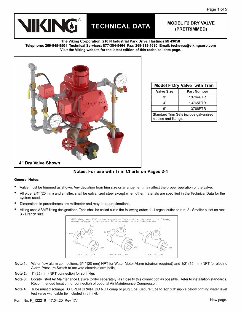
ref. Description1 1/4" x 1-1/2" (38 mm)2 1/4" x 3" (76 mm)3 1/2" x 1-1/2" (38 mm) 4 1/2" x 2" (51 mm)5 1/2" x 2-1/2" (64 mm)6 1/2" x 3" (76 mm)7 1/2" x 4" (102 mm)8 1/2" x 5" (127 mm)9 1/2" x 9" (229 mm)10 1/2" x 12" (305 mm)11 3/4" x CL12 1" x 3-1/2" (89 mm)13 1-1/2" x 7" (178 mm)14 1/4" Plug15 1/2" Plug16 3/4" Plug17 1" Plug18 1/2" Elbow19 1/2" x 1/2" x 1/2" Tee20 1/2" x 1/4" x 1/2" Tee21 1/2 x 1/2" x 1/4" Tee22 3/4" x 1/2" x 1/2" Tee23 1" x 1/2" x 1" Tee24 1/2" Union25 1/2" Ball Valve26 1-1/2" Angle Valve27 Side Outlet Valve28 Check Valve29 Spring Loaded Check Valve30 7/32" Restricted Orifice31 3/8" Connection32 3/8" Polyethylene Tube33 Drip Check34 Water Gauge35 Air Gauge36 Drain Cup40 1/16" Restricted Orifice 49 Grooved Coupling50 Butterfly Valve51 Pressure Switch52 Pressure Switch53 F2 Dry Pipe Valve 3"
Figure 1: 3” Model F2 Dry valve Trim Chart
* ** *******
See Note 1See Note 2See Note 3See Note 4
TECHNICAL DATA MoDEL F2 Dry vALvE (PrETrIMMED)
The viking Corporation, 210 N Industrial Park Drive, Hastings MI 49058Telephone: 269-945-9501 Technical Services: 877-384-5464 Fax: 269-818-1680 Email: [email protected]
visit the viking website for the latest edition of this technical data page.
Page 3 of 5
Form No. F_122216 17.04.20 Rev 17.1
****
*
*
**
***
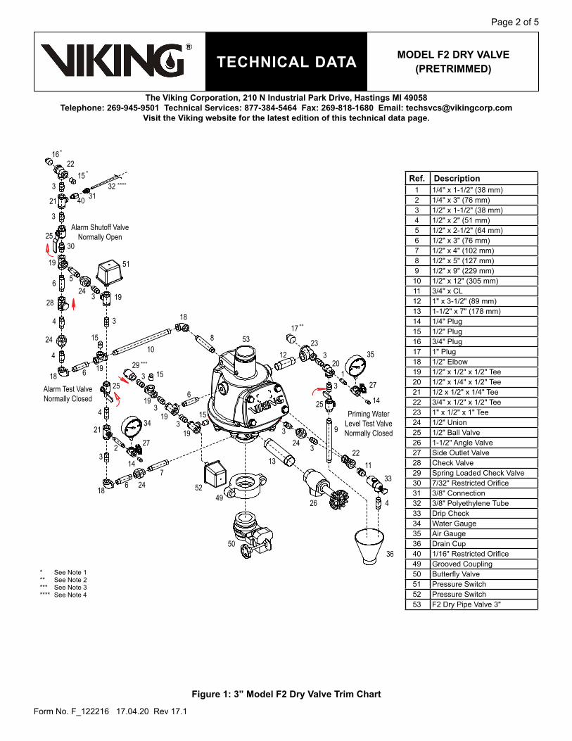
ref. Description1 1/4" x 1-1/2" (38 mm)2 1/4" x 3" (76 mm)3 1/2" x 1-1/2" (38 mm) 4 1/2" x 2" (51 mm)5 1/2" x 2-1/2" (64 mm)6 1/2" x 3" (76 mm)7 1/2" x 3-1/2" (89 mm)8 1/2" x 4" (102 mm)9 1/2" x 5" (127 mm)10 1/2" x 9" (229 mm)11 1/2" x 11-1/2" (292 mm)12 3/4" x CL13 1" x 3-1/2" (89 mm)14 2" x 6" (152 mm)15 1/4" Plug16 1/2" Plug17 3/4" Plug18 1" Plug19 1/2" Elbow20 1/2" x 1/2" x 1/2" Tee21 1/2" x 1/4" x 1/2" Tee22 1/2 x 1/2" x 1/4" Tee23 3/4" x 1/2" x 1/2" Tee24 1" x 1/2" x 1" Tee25 1/2" Union26 1/2" Ball Valve27 2" Angle Valve 28 Side Outlet Valve29 Check Valve30 Spring Loaded Check Valve31 7/32" Restricted Orifice32 3/8" Connection33 3/8" Polyethylene Tube34 Drip Check35 Water Gauge36 Air Gauge37 Drain Cup39 1/16" Restricted Orifice 48 Grooved Coupling49 Butterfly Valve50 Pressure Switch51 Pressure Switch52 F2 Dry Pipe Valve 4"
Alarm Shut-Off ValveNormally Open
Alarm Test ValveNormally Closed Priming Water
Level Test ValveNormally Closed
Figure 2: 4” Model F2 Dry valve Trim Chart
* ** *******
See Note 1See Note 2See Note 3See Note 4
TECHNICAL DATA MoDEL F2 Dry vALvE (PrETrIMMED)
The viking Corporation, 210 N Industrial Park Drive, Hastings MI 49058Telephone: 269-945-9501 Technical Services: 877-384-5464 Fax: 269-818-1680 Email: [email protected]
visit the viking website for the latest edition of this technical data page.
Page 4 of 5
Form No. F_122216 17.04.20 Rev 17.1
**
****
*
*
***
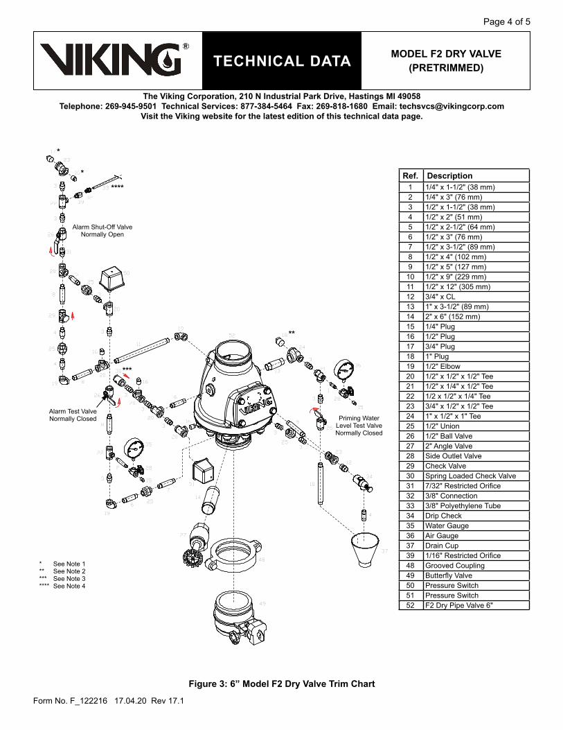
ref. Description1 1/4" x 1-1/2" (38 mm)2 1/4" x 3" (76 mm)3 1/2" x 1-1/2" (38 mm) 4 1/2" x 2" (51 mm)5 1/2" x 2-1/2" (64 mm)6 1/2" x 3" (76 mm)7 1/2" x 3-1/2" (89 mm)8 1/2" x 4" (102 mm)9 1/2" x 5" (127 mm)10 1/2" x 9" (229 mm)11 1/2" x 12" (305 mm)12 3/4" x CL13 1" x 3-1/2" (89 mm)14 2" x 6" (152 mm)15 1/4" Plug16 1/2" Plug17 3/4" Plug18 1" Plug19 1/2" Elbow20 1/2" x 1/2" x 1/2" Tee21 1/2" x 1/4" x 1/2" Tee22 1/2 x 1/2" x 1/4" Tee23 3/4" x 1/2" x 1/2" Tee24 1" x 1/2" x 1" Tee25 1/2" Union26 1/2" Ball Valve27 2" Angle Valve 28 Side Outlet Valve29 Check Valve30 Spring Loaded Check Valve31 7/32" Restricted Orifice32 3/8" Connection33 3/8" Polyethylene Tube34 Drip Check35 Water Gauge36 Air Gauge37 Drain Cup39 1/16" Restricted Orifice 48 Grooved Coupling49 Butterfly Valve50 Pressure Switch51 Pressure Switch52 F2 Dry Pipe Valve 6"
Alarm Shut-Off ValveNormally Open
Alarm Test ValveNormally Closed Priming Water
Level Test ValveNormally Closed
* ** *******
See Note 1See Note 2See Note 3See Note 4
Figure 3: 6” Model F2 Dry valve Trim Chart
TECHNICAL DATA MoDEL F2 Dry vALvE (PrETrIMMED)
The viking Corporation, 210 N Industrial Park Drive, Hastings MI 49058Telephone: 269-945-9501 Technical Services: 877-384-5464 Fax: 269-818-1680 Email: [email protected]
visit the viking website for the latest edition of this technical data page.
Page 5 of 5
Form No. F_122216 17.04.20 Rev 17.1
B
D
E(4” & 6” Valves)
E(3” Valve)
AF
G
C(3” Valve)
C(4” & 6” Valves)
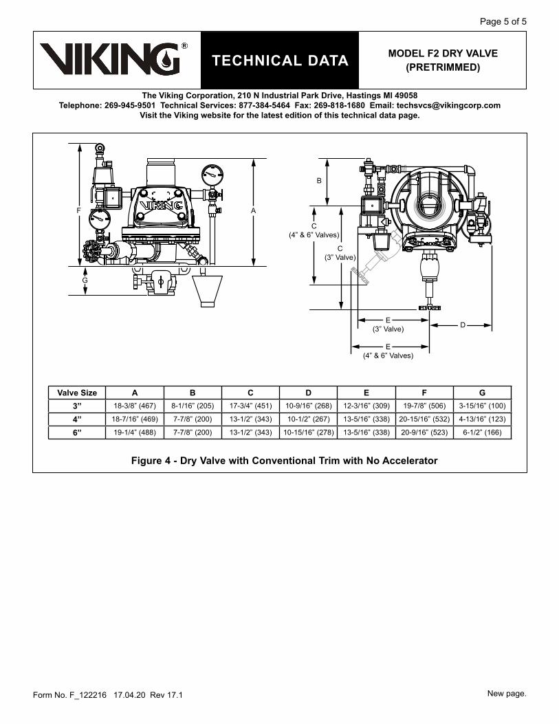
valve Size A B C D E F G3” 18-3/8” (467) 8-1/16” (205) 17-3/4” (451) 10-9/16” (268) 12-3/16” (309) 19-7/8” (506) 3-15/16” (100)
4” 18-7/16” (469) 7-7/8” (200) 13-1/2” (343) 10-1/2” (267) 13-5/16” (338) 20-15/16” (532) 4-13/16” (123)
6” 19-1/4” (488) 7-7/8” (200) 13-1/2” (343) 10-15/16” (278) 13-5/16” (338) 20-9/16” (523) 6-1/2” (166)
Figure 4 - Dry valve with Conventional Trim with No Accelerator
New page.
Recommended