2625 N. Argyle Ave. • Fresno, CA 93727(559) 291-1650 • (800) 428-7139 • FAX (559) 348-9677
TECH WEST INC.Manufacturers of Dental Vacuum
and Air Systems
2625 N. Argyle Ave. • Fresno, CA 93727(559) 291-1650 • (800) 428-7139 • FAX (559) 348-9677
TECH WEST INC.Manufacturers of Dental Vacuum
and Air Systems
ULTRA CLEANOILLESS COMPRESSOR
INSTALLATIONAND SERVICE
MANUAL


ULTRA CLEANOILLESS COMPRESSORINSTALLATION AND SERVICE MANUAL
This manual is for the installation and service of Tech West’s Ultra Clean Oilless Compressors.
CONTENTS
Installation
Location Requirements 1
Figure 1: Wire and Breaker Sizes 1
Ultra Clean Oilless Installation Steps 2
Ultra Clean Oilless Compressor Connections 3
Ultra Clean Oilless Start Up 4
Ultra Clean Oilless Maintenance 5
Ultra Clean Oilless Compressor Motor Assembly Breakdown 6-8
Desiccant Dryer Parts Breakdown 9-10
Gauge and Moisture Indicator Assembly Breakdown 11
Single Ultra Clean Oilless Compressor Assembly 12
Dual Ultra Clean Oilless Compressor Assembly 13
Triple Ultra Clean Oilless Compressor Assembly 14
TROUBLE SHOOTING
Single Compressor Trouble Shooting 15-16
Dual Compressor Trouble Shooting 17-18
Triple Compressor Trouble Shooting 19-20
Air Line Sizing Chart 21
Maintenance & Service 22-23
Notes Sheet

ULTRA CLEAN OILLESS COMPRESSORINSTALLATION
1. OILLESS COMPRESSOR LOCATION REQUIREMENTS
The Ultra Clean Oilless Compressor location should be level, accessible and well ventilated.
If the Ultra Clean Oilless Compressor will be located in a confined space, provide adequate ventilation.
Electrical
(1) Line voltage must be within the limits of Figure 1 below. (Install a “buck-boost transformer” if line voltage is not between these values.) Provide a separate line for each motor. Circuit breaker switches must be 20 - 40 amp depending on model and voltage necessary.
(2) Local code may require you to provide one quick disconnect (safety switch) for each compressor motor.
(3) See Figure 1 below for breaker size and line voltage.
CAUTION - Voltage must be 208/245 V or motor damage may occur.
CAUTION - Voltage must be 110/120 V or motor damage may occur.
1
Figure 1: Recommended Wire and Breaker Size
Single Head Compressors
Model Voltage Amperage Wire Size Recommended(Gauge) Breaker Size
ACO2S1 110/115 14.5 12 20
ACO2S2 208/230 7.2 12 20
ACO4S2 208/230 12.3 12 20
ACO4D2 208/230 14.4 10 30
ACO8D2 208/230 24.6 10 30
ACO6T2 208/230 21.6 10 30
Dual Head Compressors
Triple Head Compressors
ULTRA CLEAN OILLESS COMPRESSORINSTALLATION
2
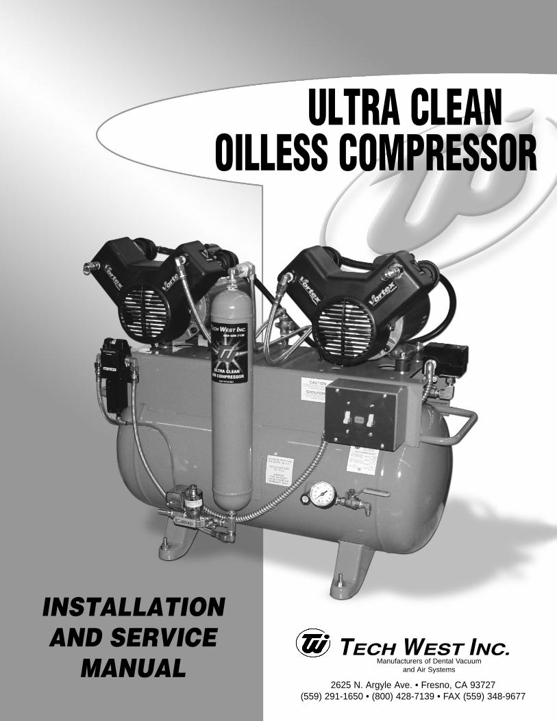
2. INSTALLATION STEPS
This dental Compressor should only be installed by qualified personnel. Should any questions ariseduring the installation, call Tech West Technical Support between the hours of 7:00 a.m. to 4:00 p.m.(Pacific Standard Time).
Place the compressor in a clean, dry, well ventilated area, on a solid, level surface. Consider soundlevel and insulate as needed. Be sure that adequate ventilation is available as the compressor is aircooled. Ambient temperature in the equipment room should be within the temperature range of 40degrees Fahrenheit minimum to 100 degrees Fahrenheit maximum.
(a) Check the shipping carton for damage. This could detect damage to the unit which might otherwise be overlooked. Remove cardboard shipping carton.
(b) Remove the Oilless Compressor from its shipping skid. Inspect the unit for damage.Oilless Compressors are shipped bolted to a pallet. This pallet is intended for shipping only and should be discarded.
(c) Remove installation kit attached to pallet. It should contain the following:
(4) Isolation Feet(1) Alternate Air Hookup Hose(1) 6’ Flexible Air Hose
(d) Install isolation feet on tank legs.
(e) Move compressor into place and level by observing bubble level on compressor platform.
(f) Wiring instructions:
(1) Have all electrical connections made by qualified personnel only. All connections should be in accordance with local codes.
(2) Use the chart on page 1 to help determine the proper line and breaker size for the unit that is being installed.
(g) Install the air line from the compressor tank to the building supply.
(h) Install the 3/4” flex alternate air hose from the compressor to a fresh air supply.
2
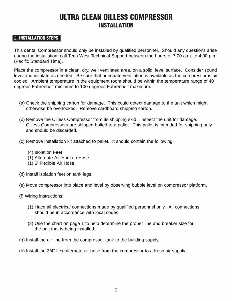
Electrical Connectionto disconnect and
electrical panel220 v
(110 v / 220 v ) on the single models only
Air OutConnection to building
supply line
3
ULTRA CLEAN OILLESS COMPRESSORINSTALLATION
2
3. CONNECTIONS
Alternate Air Connection
to fresh air supply
Figure 2
Dryer PurgeConnection

4
ULTRA CLEAN OILLESS COMPRESSORINSTALLATION
2
4. SAFETY PRECAUTIONS
• Keep fingers, foreign objects and clothing free from rotating parts and do not touch hot surfaces.
• Never attempt to service an operating unit.
• Isolate unit from system pressure and relieve backpressure before servicing
• Disconnect all power before servicing. The thermal protector in single phase motors automatically starts motor when device resets.
USE OF THIS PRODUCT IN OR NEAR EXPLOSIVE ATMOSPHERES, OR FOR
PUMPING MIXTURES OTHER THAN ATMOSPHERIC AIR MAY CAUSE AN
EXPLOSION OR FIRE, RESULTING IN PERSONAL INJURY OR DEATH.
2
5. START-UP STEPS
(a) Make sure the shut-off valve from the compressor tank is closed.
(b) Turn the breaker from the panel to the “ON” position.
(c) Turn power “ON” from the toggle switch on the compressor. Compressor should run quietly and vibration free. The storage tank should start to build pressure.
(d) The compressor will run until the pressure gauge reads 100 psi. The compressor then will automatically shut off and the dryer will purge with a quick blast of air.
(e) Using soapy water, check the compressor plumbing hook ups for leaks. Repair leaks if needed.
(f) Pressure test the entire plumbing system for leaks. Use the storage tank pressure gauge to monitor a pressure drop. After the plumbing system has been pressurized for 30 minutes, re-check the gauge for pressure drop. If there is a drop in pressure, find and repair all leaks in the office plumbing.
(g) Complete and mail in the warranty card for the compressor within ten days of installation.
AIR LEAKS ARE THE MAIN CAUSE OF COMPRESSOR FAILURES.
5
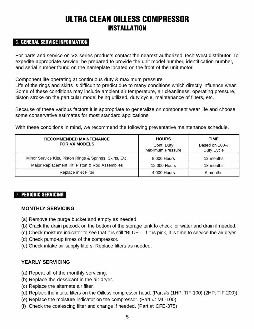
7. PERIODIC SERVICING
MONTHLY SERVICING
(a) Remove the purge bucket and empty as needed(b) Crack the drain petcock on the bottom of the storage tank to check for water and drain if needed.(c) Check moisture indicator to see that it is still “BLUE”. If it is pink, it is time to service the air dryer.(d) Check pump-up times of the compressor.(e) Check intake air supply filters. Replace filters as needed.
YEARLY SERVICING
(a) Repeat all of the monthly servicing.(b) Replace the dessicant in the air dryer.(c) Replace the alternate air filter.(d) Replace the intake filters on the Oilless compressor head. (Part #s (1HP: TIF-100) (2HP: TIF-200))(e) Replace the moisture indicator on the compressor. (Part #: MI -100)(f) Check the coalescing filter and change if needed. (Part #: CFE-375)
ULTRA CLEAN OILLESS COMPRESSORINSTALLATION
2
6. GENERAL SERVICE INFORMATION
For parts and service on VX series products contact the nearest authorized Tech West distributor. Toexpedite appropriate service, be prepared to provide the unit model number, identification number,and serial number found on the nameplate located on the front of the unit motor.
Component life operating at continuous duty & maximum pressureLife of the rings and skirts is difficult to predict due to many conditions which directly influence wear.Some of these conditions may include ambient air temperature, air cleanliness, operating pressure,piston stroke on the particular model being utilized, duty cycle, maintenance of filters, etc.
Because of these various factors it is appropriate to generalize on component wear life and choosesome conservative estimates for most standard applications.
With these conditions in mind, we recommend the following preventative maintenance schedule.
RECOMMENDED MAINTENANCEFOR VX MODELS
Minor Service Kits, Piston Rings & Springs, Skirts, Etc.
Major Replacement Kit, Piston & Rod Assemblies
Replace inlet Filter
HOURS
Cont. DutyMaximum Pressure
8,000 Hours
12,000 Hours
4,000 Hours
TIME
Based on 100%Duty Cycle
12 months
18 months
6 months

KEY PART NO. DESCRIPTION UNIT
9 POVA-100 POP OFF SAFETY VALVE 1
10 TOM-2-230 OILLESS COMP MOTOR 2 HP 230V 1
11 TFF-200 FRONT FAN ASSY 2 PH 1
12 TFC-200 FRONT FAN COVER 2 HP 1
13 TPA-200 PISTON ASSEMBLY COMPLETE 2 HP 1
14 TCA-200 CYLINDER ASSEMBLY COMPLETE 2 HP 1
15 TAF-200 AIR FILTER ASSEMBLY COMPLETE 2 HP 1
16 TIF-200 AIR FILTER ELEMENT ONLY 2 HP 1
6
KEY PART NO. DESCRIPTION UNIT
1 TOM-1-115 OILLESS COMPRESSOR MOTOR 1HP 115V 1
2 TOM-1-230 OILLESS COMPRESSOR MOTOR 1HP 230V 1
3 TFF-100 FRONT FAN ASSY. 1 HP 1
4 TFC-100 FRONT FAN COVER 1 HP 1
5 TPA-100 PISTON ASSEMBLY COMPLETE 1 HP 1
6 TCA-100 CYLINDER ASSEMBLY COMPLETE 1 HP 1
7 TAF-100 AIR FILTER ASSEMBLY COMPLETE 1 HP 1
8 TIF-100 AIR FILTER ELEMENT ONLY H HP 1
9 POVA-100 POP OFF SAFETY VALVE 1
OIL-FREE COMPRESSOR MOTOR 1HP
ULTRA CLEAN OILLESS COMPRESSORPARTS LIST
OIL-FREE COMPRESSOR MOTOR 2HP

7
OIL-FREE COMPRESSOR 1HP
8
7
69
12
3
4
5

8
OIL-FREE COMPRESSOR 2HP
16
15
13
9
10
11
12
14

9
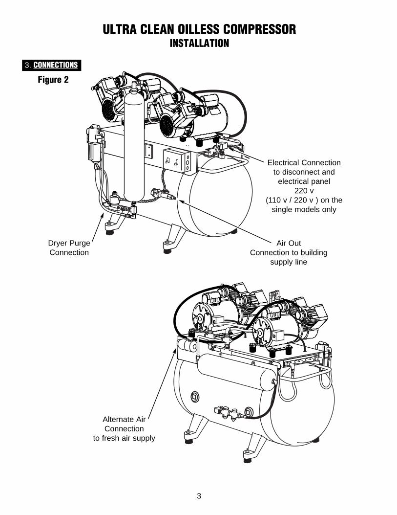
REAR VIEW ASSEMBLY AND PARTS LIST
KEY PART NO. DESCRIPTION UNIT
1 CV-375 3/8 CHECK VALVE 2
2 CPT-100 COMPRESSOR PURGE TANK 1
3. CV-250 1/4 CHECK VALVE 1-3
4 HA-10-250 1/4 HOSE ASSEMBLY - 10” LONG 1
5 DPC-1 DRYER PRE COOLER SINGLE COMPRESSOR 1
6 DPC-2 DRYER PRE COOLER DUAL & TRIPLE COMPRESSOR 1
7 RFV-100 RUBBER MOUNTING FEET 4
4
3
2
1
7
56

10
KE
YPA
RT
NO
.D
ES
CR
IPT
ION
UN
IT
1D
SV
-115
115V
PU
RG
E S
OL
EN
OID
VA
LVE
1
2D
SV
-230
230V
PU
RG
E S
OL
EN
OID
VA
LVE
1
3A
S-5
001/
2 F
ILT
ER
AS
SY
1
4R
DC
-100
RE
PL
AC
EM
EN
T D
ES
SIC
AN
T T
AN
K1
5M
V-2
50M
ET
ER
ING
VA
LVE
1
6S
N-2
50-C
LS
TAIN
LE
SS
ST
EE
L N
IPP
LE
1/4
3
7F
E-4
-6F
LA
IR F
ITT
ING
1/4
X 3
/81
8V
B-2
50B
AL
L V
ALV
E 1
/41
9B
T-2
50B
RA
SS
TE
E 1
/42
10P
FE
-4-2
PO
LY F
LO
FIT
TIN
G1
11M
SD
-100
MO
LE
CU
LA
R-S
IER
E
1 L
B2
12M
SD
-200
AC
TIV
AT
ED
AL
UM
INA
1 L
B2
NEW DESICCANT AIR DRYER ASSEMBLY
4
3
6
9
7
8
9
5
12

11
0
10
20
3040 50
60
7
8
90100
psi
100
90
80
706050
0
0
20
10
0
2
4
4
3
3
2
5
5
8
6
7
7
1
1
KEY PART NO. DESCRIPTION UNIT
1 CPG-250 COMPRESSOR GAUGE 1
2 BV-250 1/4” BALL VALVE 1
3 MI-100 MOISTURE INDICATOR 1
4 FA-4-4 1/4” FLARE HOSE FITTING 1
5 BN-250-CL 1/4” BRASS CLOSE NIPPLE 1
6 BT-250 1/4” BRASS TEE 1
7 BSE-250 1/4” BRASS ELBOW 1
8 BPC-4 1/4” BRASS CROSS 1
GAUGE AND CUT-OFF ASSEMBLY
SINGLE COMPRESSOR CONFIGURATION
DUAL AND TRIPLE COMPRESSOR CONFIGURATION

KEY PART NO. DESCRIPTION UNIT
1 SBHA-21-375 STEEL BRAID HOSE ASSEMBLY 1
2 SBHA-7.5-375E STEEL BRAID HOSE ASSEMBLY 1
3 SBHA-11-375E STEEL BRAID HOSE ASSEMBLY 1
4 FPH-375 PURGE FLEX HOSE CLEAR PER FT
5 PFT-250 POLY FLO TUBE 1/4 PER FT
6 PFT-625 POLY FLO TUBE 5/8 PER FT
7 CFA-375 COALESCING FILTER 3/8 1
8 CFE-375 COALESCING FILTER ELEMENT ONLY 1
9 DPB-100 DRYER PURGE BUCKET 1
10 IRC-GAST RUBBER MOUNTING FEET 4
11 CPT-100 COMPRESSOR PURGE TANK 1
12 RDC-100 REPLACEMENT DESICCANT CARTRIDGE 1
13 DSV-115 PURGE VALVE SOLENOID VALVE 115V 1
14 DSV-230 PURGE VALVE SOLENOID VALVE 230V 1
15 TOM-1-115 OILLESS MOTOR 1 HP 115V 1
16 TOM-1-230 OILLESS MOTOR 1 HP 230V 1
17 RFV-100 RUBBER MOUNTING FEET 4
18 PSC-2 PRESSURE SWITCH 1
19 POVA-100 SAFETY POP OFF VALVE 1
12
SINGLE ULTRA CLEAN OILLESS COMPRESSOR
2 10
83
6
1516
11
17
18
7
5
113
14
129
4
19

13
2
8 3
616
17
7
5
1
12
9
4
KEY PART NO. DESCRIPTION UNIT
1 SBHA-21-375 STEEL BRAID HOSE ASSEMBLY 1
2 SBHA-10-375E STEEL BRAID HOSE ASSEMBLY 1
3 SBHA-9-375E STEEL BRAID HOSE ASSEMBLY 1
4 FPH-375 PURGE FLEX HOSE CLEAR PER FT
5 PFT-250 POLY FLO TUBE 1/4 PER FT
6 PFT-625 POLY FLO TUBE 5/8 PER FT
7 CFA-375 COALESCING FILTER 3/8 1
8 CFE-375 COALESCING FILTER ELEMENT ONLY 1
9 DPB-100 DRYER PURGE BUCKET 1
10 RIC-GAST RUBBER MOUNTING FEET 8
11 CPT-100 COMPRESSOR PURGE TANK 1
12 RDC-100 REPLACEMENT DESICCANT CARTRIDGE 1
13 CV-250 1/4 CHECK VALVE 2
14 DSV-230 PURGE VALVE SOLENOID VALVE 230V 1
15 SBHA-18-375 STEEL BRAID HOSE ASSEMBLY 2
16 TOM-1-230 OILLESS MOTOR 1 HP 230V 2
17 RFV-100 RUBBER MOUNTING FEET 4
18 PSC-3 PRESSURE SWITCH 1
19 POVA-100 SAFETY POP OFF VALVE 1
DUAL ULTRA CLEAN OILLESS COMPRESSOR
11
13
1018
14
15
19

14
KEY PART NO. DESCRIPTION UNIT
1 SBHA-21-375 STEEL BRAID HOSE ASSEMBLY 1
2 SBHA-10-375E STEEL BRAID HOSE ASSEMBLY 1
3 SBHA-9-375E STEEL BRAID HOSE ASSEMBLY 1
4 FPH-375 PURGE FLEX HOSE CLEAR PER FT
5 PFT-250 POLY FLO TUBE 1/4 PER FT
6 PFT-625 POLY FLO TUBE 5/8 PER FT
7 CFA-375 COALESCING FILTER 3/8 1
8 CFE-375 COALESCING FILTER ELEMENT ONLY 1
9 DPB-100 DRYER PURGE BUCKET 1
10 RIC-GAST RUBBER MOUNTING FEET 12
11 CPT-100 COMPRESSOR PURGE TANK 1
12 RDC-100 REPLACEMENT DESICCANT CARTRIDGE 1
13 CV-250 1/4 CHECK VALVE 3
14 DSV-230 PURGE VALVE SOLENOID VALVE 230V 1
15 SBHA-18-375 STEEL BRAID HOSE ASSEMBLY 3
16 TOM-1-230 OILLESS MOTOR 1 HP 230V 3
17 RFV-100 RUBBER MOUNTING FEET 6
18 PSC-3 PRESSURE SWITCH 1
19 POVA-100 SAFETY POP OFF VALVE 1
TRIPLE ULTRA CLEAN OILLESS COMPRESSOR
6
16
2
8
7
5
1
12
9
4
1417
18
3
10
15
13
11
19

15
DO
ES
AIR
C
OM
PR
ES
SO
RR
UN
?
Doe
s co
mpr
esso
r ru
nfo
r a
few
sec
onds
,“c
hugs
”, t
hen
stop
s?
Doe
s co
mpr
esso
r pr
es-
suriz
e fr
om 8
0 to
100
psi i
n le
ss t
han
2m
inut
e w
ith n
o ai
rbe
ing
used
?
Doe
s co
mpr
esso
rcy
cle
with
no
air
bein
g us
ed?
YE
SN
OY
ES
NO
GO
ON
TO
TH
E N
EX
TPA
GE
.
Are
the
re le
aks
inco
mpr
esso
r or
inof
fice
pipi
ng s
yste
m?
Doe
s ai
rbl
eed
out
the
purg
eva
lve
whe
nun
it is
ru
nnin
g?
Cle
an
or
repl
ace.
Rep
lace
inta
ke
filte
r.
NO
NO
Che
ck v
olta
ge a
tth
e va
lve
and
mak
e su
re v
alve
iscl
osed
.
Doe
sun
load
erva
lve
pres
-su
re s
witc
hor
flo
atas
sem
bly
seat
whi
leru
nnin
g?
NO
YE
S
Trou
ble
Shoo
ting
Char
tS
ing
le U
ltra
Cle
an O
illes
s C
om
pre
sso
r
Sing
le U
ltra
Clea
n Oi
lless
Com
pres
sor D
iagr
am
YE
S
Is t
he m
oist
ure
indi
cato
r pi
nk?
YE
S
Is in
take
filte
rcl
ogge
d?
Is t
here
suf
ficie
ntpr
essu
re b
uild
-up
with
hea
d di
scha
rge
line
rem
oved
?
YE
S
NO
Def
ectiv
ehe
ad,
cont
act
Tech
Wes
t.
No
te:
Clo
sesh
ut o
ff va
lve.
Pum
p up
tan
k to
100
psi.
If pr
es-
sure
is m
ain-
tain
ed f
or 1
5-20
min
., le
ak is
inof
fice
lines
.
YE
SLo
cate
and
repa
ir.
NO
NO
Doe
s pu
rge
valv
esy
stem
func
tion
prop
erly
?
YE
S
Doe
s co
m-
pres
sor
run
too
hot
or t
oofr
eque
nt?
NO
Che
ck f
or p
rope
rvo
ltage
. U
se b
uck-
boos
t if
need
ed.
NO
1. L
ocat
e an
d re
pair
leak
s.2.
Ven
tilat
e if
room
isab
ove
100
deg.
F.
3. C
onta
ct c
ompr
esso
rm
ay b
e un
ders
ized
.
YE
S
YE
S
Ser
vice
dry
er a
ndre
plac
e m
oist
ure
indi
cato
r.
YE
S
Che
ck v
olta
ge s
up-
plie
d to
the
co
mpr
esso
r.
YE
S
Def
ectiv
ehe
ad,
cont
act
Tech
Wes
t.
YE
S
NO
Doe
s ai
r le
akfr
om u
nloa
der
valv
e or
the
purg
e m
uffle
rco
ntin
uous
lyun
til u
nit
cycl
esag
ain?
Mak
e su
re t
hat
the
drye
r va
lve
is c
los-
ing
prop
erly
.

16
CH
EC
KF
OR
:1.
Bro
ken
or lo
ose
wire
.2.
Def
ectiv
e pr
essu
resw
itch.
3. D
efec
tive
ON
/OF
Fsw
itch.
4. E
xces
sive
vol
tage
drop
acr
oss
pow
erlin
es.
NO
TE
:V
olta
gesh
ould
be
+ o
r -
10%
of
ratin
g.
Is t
here
suf
ficie
ntvo
ltage
at
mot
orte
rmin
als
whi
lem
otor
trie
s to
sta
rt?
GO
ON
TO
TH
E N
EX
TPA
GE
.
CO
MP
RE
SS
OR
DO
ES
NO
T R
UN
OR
RU
NS
FO
RO
NLY
A F
EW
SE
CO
ND
S.
YE
S
Doe
s he
adru
n w
ith d
is-
char
ge li
nedi
scon
nect
ed?
NO
Is t
here
suf
fi-ci
ent
volta
geat
dis
conn
ect
box?
Blo
ckag
e in
air
line
loca
te&
rep
air.
YE
S
Inst
all
Tech
Wes
ttr
ansf
orm
er.
NO
YE
SN
O
YE
S
Is t
here
resi
stan
ceris
e ac
ross
the
capa
ci-
tors
?
YE
S
Rep
lace
defe
ctiv
eca
paci
tors
.
NO
Turn
pow
er o
ff.R
emov
e fa
n gu
ard.
Try
turn
ing
fan
byha
nd.
If it
does
n’t
turn
, co
ntac
t he
adm
ay b
e fr
ozen
.
NO
TE
:S
hort
cap
acito
rle
ads.
Che
ck r
esis
-ta
nce
rise.
If
nore
sist
ance
ris
e,re
plac
e.
Wiri
ng D
iagr
amS
ing
le U
ltra
Cle
an O
illes
s C
om
pre
sso
r
115v 230v

17
Doe
s co
mpr
esso
r ru
nfo
r a
few
sec
onds
,“c
hugs
”, t
hen
stop
s?
Doe
s co
mpr
esso
r pr
es-
suriz
e fr
om 8
0 to
100
0ps
i in
less
tha
n 1
min
ute
with
no
air
bein
g us
ed?
Doe
s co
mpr
esso
rcy
cle
with
no
air
bein
g us
ed?
YE
SN
OY
ES
GO
ON
TO
TH
E N
EX
TPA
GE
.
Are
the
re le
aks
inco
mpr
esso
r or
inof
fice
pipi
ng s
yste
m?
Cle
an
or
repl
ace.
Rep
lace
inta
ke
filte
r.
NO
NO
YE
S
Trou
ble
Shoo
ting
Char
tTw
in U
ltra
Cle
an O
illes
s C
om
pre
sso
r
Dual
Ultr
a Cl
ean
Oille
ss C
ompr
esso
r Dia
gram
Is in
take
filte
rcl
ogge
d?
Is t
here
suf
ficie
ntpr
essu
re b
uild
-up
with
hea
d di
scha
rge
line
rem
oved
?
YE
S
NO
Def
ectiv
ehe
ad,
cont
act
Tech
Wes
t.
No
te:
Clo
sesh
ut o
ff va
lve.
Pum
p up
tan
k to
100
psi.
If pr
es-
sure
is m
ain-
tain
ed f
or 1
5-20
min
., le
ak is
inof
fice
lines
.
YE
SLo
cate
and
repa
ir.
NO
Def
ectiv
ehe
ad,
cont
act
Tech
Wes
t.
YE
S
NO
Loca
tean
d re
pair.
YE
S
Is t
here
abl
ocka
ge in
air
lines
?
YE
SN
O
Is t
he m
oist
ure
indi
cato
r pi
nk?
NO
Doe
sun
load
erva
lve
syst
emfu
nctio
npr
oper
ly?
YE
S
Doe
s co
m-
pres
sor
run
too
hot
or t
oofr
eque
nt?
NO
Che
ck f
or p
rope
rvo
ltage
. U
se b
uck-
boos
t if
need
ed.
NO
1. L
ocat
e an
d re
pair
leak
s.2.
Ven
tilat
e if
room
isab
ove
100
deg.
F.
3. C
onta
ct c
ompr
esso
rm
ay b
e un
ders
ized
.
YE
S
Ser
vice
dry
er a
ndre
plac
e m
oist
ure
indi
cato
r.
YE
S
NO
Che
ck v
olta
ge a
tth
e va
lve
and
mak
e su
re v
alve
iscl
osed
.
Doe
sun
load
erva
lve
pres
-su
re s
witc
hor
flo
atas
sem
bly
seat
whi
leru
nnin
g?
Che
ck v
olta
ge s
up-
plie
d to
the
co
mpr
esso
r.
YE
S
Doe
s ai
rbl
eed
out
the
relie
fva
lve?
NO
YE
S
YE
S
Doe
s ai
r le
akfr
om u
nloa
der
valv
e or
the
purg
e m
uffle
rco
ntin
uous
lyun
til u
nit
cycl
esag
ain?
Mak
e su
re t
hat
the
drye
r va
lve
is c
los-
ing
prop
erly
.
DO
ES
AIR
C
OM
PR
ES
SO
RR
UN
?

18
Wiri
ng D
iagr
amD
ual
Ult
ra C
lean
Oill
ess
Co
mp
ress
or
CH
EC
KF
OR
:1.
Bro
ken
or lo
ose
wire
.2.
Def
ectiv
e pr
essu
resw
itch.
3. D
efec
tive
ON
/OF
Fsw
itch.
4. E
xces
sive
vol
tage
drop
acr
oss
pow
erlin
es.
NO
TE
:V
olta
gesh
ould
be
+ o
r -
10%
of
ratin
g.
Is t
here
suf
ficie
ntvo
ltage
at
mot
orte
rmin
als
whi
lem
otor
trie
s to
sta
rt?
GO
ON
TO
TH
E N
EX
TPA
GE
.
CO
MP
RE
SS
OR
DO
ES
NO
T R
UN
OR
RU
NS
FO
RO
NLY
A F
EW
SE
CO
ND
S.
YE
S
Doe
s he
adru
n w
ith d
is-
char
ge li
nedi
scon
nect
ed?
NO
Is t
here
suf
fi-ci
ent
volta
geat
dis
conn
ect
box?
Blo
ckag
e in
air
line
loca
te&
rep
air.
YE
S
Inst
all
Tech
Wes
ttr
ansf
orm
er.
NO
YE
SN
O
YE
S
Is t
here
resi
stan
ceris
e ac
ross
the
capa
ci-
tors
?
YE
S
Rep
lace
defe
ctiv
eca
paci
tors
.
NO
Turn
pow
er o
ff.R
emov
e fa
n gu
ard.
Try
turn
ing
fan
byha
nd.
If it
does
n’t
turn
, co
ntac
t he
adm
ay b
e fr
ozen
.
NO
TE
:S
hort
cap
acito
rle
ads.
Che
ck r
esis
-ta
nce
rise.
If
nore
sist
ance
ris
e,re
plac
e.
230v

19
Trou
ble
Shoo
ting
Char
tTr
iple
Ult
ra C
lean
Oill
ess
Co
mp
ress
or
Doe
s co
mpr
esso
r ru
nfo
r a
few
sec
onds
,“c
hugs
”, t
hen
stop
s?
Doe
s co
mpr
esso
r pr
es-
suriz
e fr
om 8
0 to
100
0ps
i in
less
tha
n 1
min
ute
with
no
air
bein
g us
ed?
Doe
s co
mpr
esso
rcy
cle
with
no
air
bein
g us
ed?
YE
SN
OY
ES
GO
ON
TO
TH
E N
EX
TPA
GE
.
Are
the
re le
aks
inco
mpr
esso
r or
inof
fice
pipi
ng s
yste
m?
Cle
an
or
repl
ace.
Rep
lace
inta
ke
filte
r.
NO
NO
YE
S
Trip
le U
ltra
Clea
n Oi
lless
Com
pres
sor D
iagr
am
Is in
take
filte
rcl
ogge
d?
Is t
here
suf
ficie
ntpr
essu
re b
uild
-up
with
hea
d di
scha
rge
line
rem
oved
?
YE
S
NO
Def
ectiv
ehe
ad,
cont
act
Tech
Wes
t.
No
te:
Clo
sesh
ut o
ff va
lve.
Pum
p up
tan
k to
100
psi.
If pr
es-
sure
is m
ain-
tain
ed f
or 1
5-20
min
., le
ak is
inof
fice
lines
.
YE
SLo
cate
and
repa
ir.
NO
Def
ectiv
ehe
ad,
cont
act
Tech
Wes
t.
YE
S
NO
Loca
tean
d re
pair.
YE
S
Is t
here
abl
ocka
ge in
air
lines
?
YE
SN
O
Is t
he m
oist
ure
indi
cato
r pi
nk?
NO
Doe
sun
load
erva
lve
syst
emfu
nctio
npr
oper
ly?
YE
S
Doe
s co
m-
pres
sor
run
too
hot
or t
oofr
eque
nt?
NO
Che
ck f
or p
rope
rvo
ltage
. U
se b
uck-
boos
t if
need
ed.
NO
1. L
ocat
e an
d re
pair
leak
s.2.
Ven
tilat
e if
room
isab
ove
100
deg.
F.
3. C
onta
ct c
ompr
esso
rm
ay b
e un
ders
ized
.
YE
S
Ser
vice
dry
er a
ndre
plac
e m
oist
ure
indi
cato
r.
YE
S
NO
Che
ck v
olta
ge a
tth
e va
lve
and
mak
e su
re v
alve
iscl
osed
.
Doe
sun
load
erva
lve
pres
-su
re s
witc
hor
flo
atas
sem
bly
seat
whi
leru
nnin
g?
Che
ck v
olta
ge s
up-
plie
d to
the
co
mpr
esso
r.
YE
S
Doe
s ai
rbl
eed
out
the
relie
fva
lve?
NO
YE
S
YE
S
Doe
s ai
r le
akfr
om u
nloa
der
valv
e or
the
purg
e m
uffle
rco
ntin
uous
lyun
til u
nit
cycl
esag
ain?
Mak
e su
re t
hat
the
drye
r va
lve
is c
los-
ing
prop
erly
.
DO
ES
AIR
C
OM
PR
ES
SO
RR
UN
?

20
Wiri
ng D
iagr
amTr
iple
Ult
ra C
lean
Oill
ess
Co
mp
ress
or
CH
EC
KF
OR
:1.
Bro
ken
or lo
ose
wire
.2.
Def
ectiv
e pr
essu
resw
itch.
3. D
efec
tive
ON
/OF
Fsw
itch.
4. E
xces
sive
vol
tage
drop
acr
oss
pow
erlin
es.
NO
TE
:V
olta
gesh
ould
be
+ o
r -
10%
of
ratin
g.
Is t
here
suf
ficie
ntvo
ltage
at
mot
orte
rmin
als
whi
lem
otor
trie
s to
sta
rt?
GO
ON
TO
TH
E N
EX
TPA
GE
.
CO
MP
RE
SS
OR
DO
ES
NO
T R
UN
OR
RU
NS
FO
RO
NLY
A F
EW
SE
CO
ND
S.
YE
S
Doe
s he
adru
n w
ith d
is-
char
ge li
nedi
scon
nect
ed?
NO
Is t
here
suf
fi-ci
ent
volta
geat
dis
conn
ect
box?
Blo
ckag
e in
air
line
loca
te&
rep
air.
YE
S
Inst
all
Tech
Wes
ttr
ansf
orm
er.
NO
YE
SN
O
YE
S
Is t
here
resi
stan
ceris
e ac
ross
the
capa
ci-
tors
?
YE
S
Rep
lace
defe
ctiv
eca
paci
tors
.
NO
Turn
pow
er o
ff.R
emov
e fa
n gu
ard.
Try
turn
ing
fan
byha
nd.
If it
does
n’t
turn
, co
ntac
t he
adm
ay b
e fr
ozen
.
NO
TE
:S
hort
cap
acito
rle
ads.
Che
ck r
esis
-ta
nce
rise.
If
nore
sist
ance
ris
e,re
plac
e.
230v

21
Maintenance & Service / Notes

22
Maintenance & Service / Notes

23
Maintenance & Service / Notes
Recommended