1 Rinnai Rack Installation
Tankless Rack System (TRS) Installa on Manual Additional information can be obtained from the appliance manual.
— Do not store or use gasoline or other flammable vapors and liquids in the vicinity of this or any other appliance.
— WHAT TO DO IF YOU SMELL GAS
• Do not try to light any appliance. • Do not touch any electrical switch; do not use any phone in your building. • Immediately call your gas supplier from a neighbor’s phone. Follow the gas supplier’s instruc ons. • If you cannot reach your gas supplier, call the fire department.
— Installa on and service must be performed by a licensed professional.
If the informa on in these instruc ons is not followed exactly, a fire or explosion may result causing property damage, personal injury or death.
WARNING
Free Standing Rack (6 water heaters)
Wall Mounted Rack (4 water heaters)
2 Rinnai Rack Installation
Description ............................................................ 3
Venting Options ..................................................... 3
TRS Part Nos. and Main Components .................. 4
Specifications ........................................................ 5
Clearances ............................................................ 7
Hoisting ................................................................. 8
Mounting Wall Racks ............................................ 9
Securing Free Standing Racks ............................. 9
Relief Valve Piping .............................................. 10
Piping for Multiple Racks .................................... 10
Parallel Piping Drawing ....................................... 11
End caps / Connections ...................................... 12
Replacement Parts .............................................. 12
Condensate Drain ............................................... 13
Checklist for Plumbing ......................................... 13
Installation of Gas Supply .................................... 14
Connecting Electricity .......................................... 14
MSB Installation................................................... 15
Final Checklist ..................................................... 17
Extended Limited Labor Warranty ....................... 18
Safety Symbols
Indicates an imminently hazardous situation which, if not avoided, will result in death or serious injury.
Indicates a potentially hazardous situation which, if not avoided, could result in death or serious injury.
Indicates a potentially hazardous situation which, if not avoided, could result in minor or moderate injury. It may also be used to alert against unsafe practices.
This is the safety alert symbol. This symbol alerts you to potential hazards that can kill or hurt you and others.
DANGER
CAUTION
WARNING
A licensed professional must install the common ven ng.
The installer should have skills such as
• connec ng gas lines, water lines, valves, and electricity
• knowledge of applicable na onal, state, and local codes
If you lack these skills, contact a licensed professional.
Installa on
Table of Contents
3 Rinnai Rack Installation
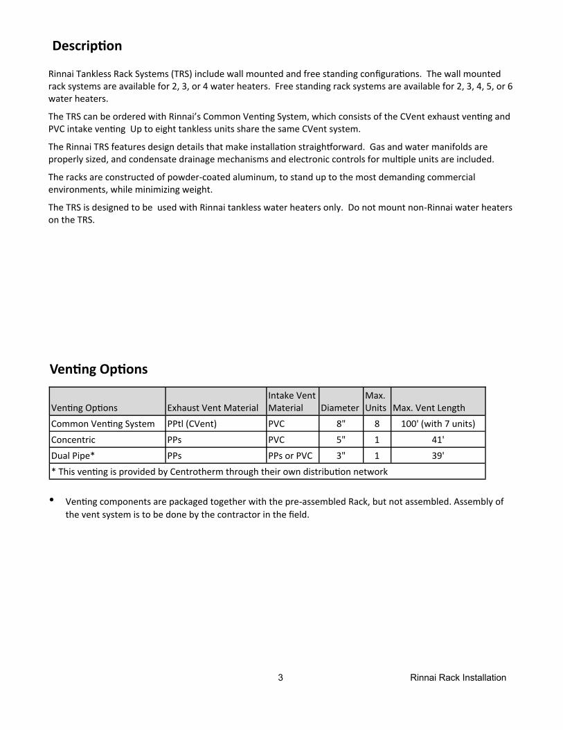
Descrip on
Rinnai Tankless Rack Systems (TRS) include wall mounted and free standing configura ons. The wall mounted rack systems are available for 2, 3, or 4 water heaters. Free standing rack systems are available for 2, 3, 4, 5, or 6 water heaters.
The TRS can be ordered with Rinnai’s Common Ven ng System, which consists of the CVent exhaust ven ng and PVC intake ven ng Up to eight tankless units share the same CVent system.
The Rinnai TRS features design details that make installa on straigh orward. Gas and water manifolds are properly sized, and condensate drainage mechanisms and electronic controls for mul ple units are included.
The racks are constructed of powder‐coated aluminum, to stand up to the most demanding commercial environments, while minimizing weight.
The TRS is designed to be used with Rinnai tankless water heaters only. Do not mount non‐Rinnai water heaters on the TRS.
Ven ng Op ons
Ven ng Op ons Exhaust Vent Material Intake Vent Material Diameter
Max. Units Max. Vent Length
Common Ven ng System PPtl (CVent) PVC 8" 8 100' (with 7 units)
Concentric PPs PVC 5" 1 41'
Dual Pipe* PPs PPs or PVC 3" 1 39'
* This ven ng is provided by Centrotherm through their own distribu on network
• Ven ng components are packaged together with the pre‐assembled Rack, but not assembled. Assembly of the vent system is to be done by the contractor in the field.
4 Rinnai Rack Installation
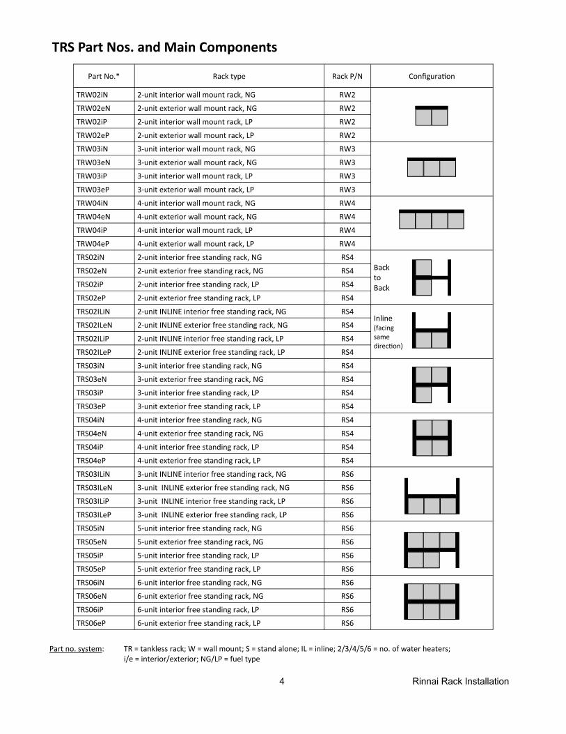
TRS Part Nos. and Main Components
Part no. system: TR = tankless rack; W = wall mount; S = stand alone; IL = inline; 2/3/4/5/6 = no. of water heaters; i/e = interior/exterior; NG/LP = fuel type
Part No.* Rack type Rack P/N Configura on
TRW02iN 2‐unit interior wall mount rack, NG RW2
TRW02eN 2‐unit exterior wall mount rack, NG RW2
TRW02iP 2‐unit interior wall mount rack, LP RW2
TRW02eP 2‐unit exterior wall mount rack, LP RW2
TRW03iN 3‐unit interior wall mount rack, NG RW3
TRW03eN 3‐unit exterior wall mount rack, NG RW3
TRW03iP 3‐unit interior wall mount rack, LP RW3
TRW03eP 3‐unit exterior wall mount rack, LP RW3
TRW04iN 4‐unit interior wall mount rack, NG RW4
TRW04eN 4‐unit exterior wall mount rack, NG RW4
TRW04iP 4‐unit interior wall mount rack, LP RW4
TRW04eP 4‐unit exterior wall mount rack, LP RW4
TRS02iN 2‐unit interior free standing rack, NG RS4 Back to Back
TRS02eN 2‐unit exterior free standing rack, NG RS4
TRS02iP 2‐unit interior free standing rack, LP RS4
TRS02eP 2‐unit exterior free standing rack, LP RS4
TRS02ILiN 2‐unit INLINE interior free standing rack, NG RS4 Inline (facing same direc on)
TRS02ILeN 2‐unit INLINE exterior free standing rack, NG RS4
TRS02ILiP 2‐unit INLINE interior free standing rack, LP RS4
TRS02ILeP 2‐unit INLINE exterior free standing rack, LP RS4
TRS03iN 3‐unit interior free standing rack, NG RS4
TRS03eN 3‐unit exterior free standing rack, NG RS4
TRS03iP 3‐unit interior free standing rack, LP RS4
TRS03eP 3‐unit exterior free standing rack, LP RS4
TRS04iN 4‐unit interior free standing rack, NG RS4
TRS04eN 4‐unit exterior free standing rack, NG RS4
TRS04iP 4‐unit interior free standing rack, LP RS4
TRS04eP 4‐unit exterior free standing rack, LP RS4
TRS03ILiN 3‐unit INLINE interior free standing rack, NG RS6
TRS03ILeN 3‐unit INLINE exterior free standing rack, NG RS6
TRS03ILiP 3‐unit INLINE interior free standing rack, LP RS6
TRS03ILeP 3‐unit INLINE exterior free standing rack, LP RS6
TRS05iN 5‐unit interior free standing rack, NG RS6
TRS05eN 5‐unit exterior free standing rack, NG RS6
TRS05iP 5‐unit interior free standing rack, LP RS6
TRS05eP 5‐unit exterior free standing rack, LP RS6
TRS06iN 6‐unit interior free standing rack, NG RS6
TRS06eN 6‐unit exterior free standing rack, NG RS6
TRS06iP 6‐unit interior free standing rack, LP RS6
TRS06eP 6‐unit exterior free standing rack, LP RS6
5 Rinnai Rack Installation
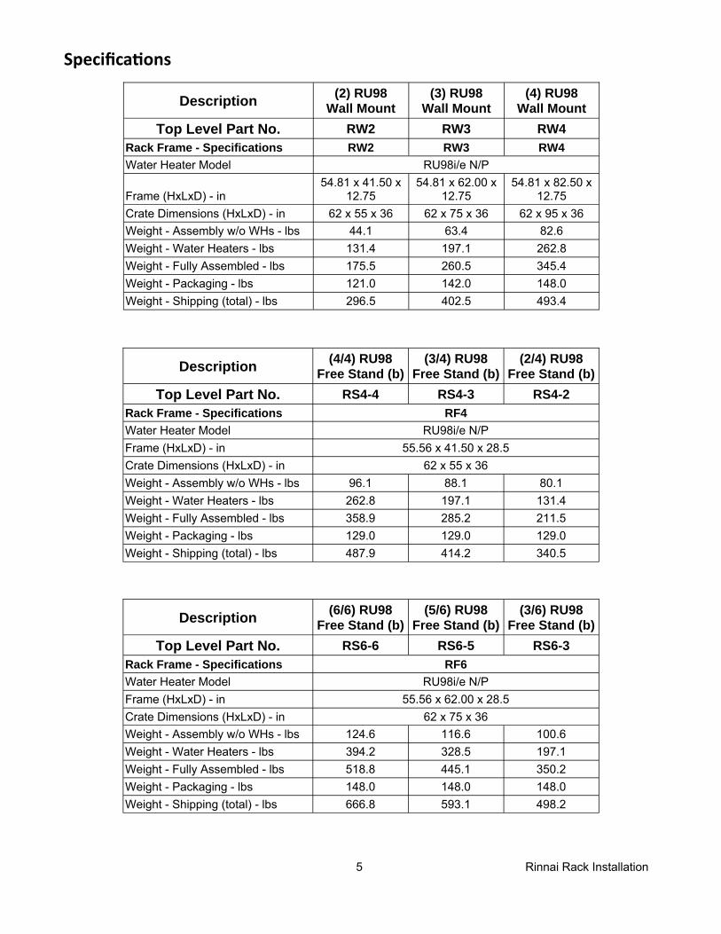
Specifica ons
Description (4/4) RU98 Free Stand (b)
(3/4) RU98 Free Stand (b)
(2/4) RU98 Free Stand (b)
Top Level Part No. RS4-4 RS4-3 RS4-2 Rack Frame - Specifications Water Heater Model RU98i/e N/P Frame (HxLxD) - in 55.56 x 41.50 x 28.5 Crate Dimensions (HxLxD) - in 62 x 55 x 36 Weight - Assembly w/o WHs - lbs 96.1 88.1 80.1 Weight - Water Heaters - lbs 262.8 197.1 131.4 Weight - Fully Assembled - lbs 358.9 285.2 211.5 Weight - Packaging - lbs 129.0 129.0 129.0 Weight - Shipping (total) - lbs 487.9 414.2 340.5
RF4
Description (6/6) RU98 Free Stand (b)
(5/6) RU98 Free Stand (b)
(3/6) RU98 Free Stand (b)
Top Level Part No. RS6-6 RS6-5 RS6-3 Rack Frame - Specifications Water Heater Model RU98i/e N/P Frame (HxLxD) - in 55.56 x 62.00 x 28.5 Crate Dimensions (HxLxD) - in 62 x 75 x 36 Weight - Assembly w/o WHs - lbs 124.6 116.6 100.6 Weight - Water Heaters - lbs 394.2 328.5 197.1 Weight - Fully Assembled - lbs 518.8 445.1 350.2 Weight - Packaging - lbs 148.0 148.0 148.0 Weight - Shipping (total) - lbs 666.8 593.1 498.2
RF6
Description (2) RU98 Wall Mount
(3) RU98 Wall Mount
(4) RU98 Wall Mount
Top Level Part No. RW2 RW3 RW4 Rack Frame - Specifications RW2 RW3 RW4 Water Heater Model
Frame (HxLxD) - in 54.81 x 41.50 x
12.75 54.81 x 62.00 x
12.75 54.81 x 82.50 x
12.75 Crate Dimensions (HxLxD) - in 62 x 55 x 36 62 x 75 x 36 62 x 95 x 36 Weight - Assembly w/o WHs - lbs 44.1 63.4 82.6 Weight - Water Heaters - lbs 131.4 197.1 262.8 Weight - Fully Assembled - lbs 175.5 260.5 345.4 Weight - Packaging - lbs 121.0 142.0 148.0 Weight - Shipping (total) - lbs 296.5 402.5 493.4
RU98i/e N/P
6 Rinnai Rack Installation
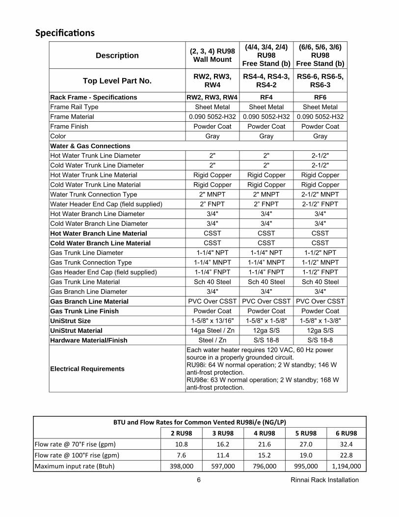
Specifica ons
Description (2, 3, 4) RU98 Wall Mount
(4/4, 3/4, 2/4) RU98
Free Stand (b)
(6/6, 5/6, 3/6) RU98
Free Stand (b)
Top Level Part No. RW2, RW3, RW4
RS4-4, RS4-3, RS4-2
RS6-6, RS6-5, RS6-3
Rack Frame - Specifications RW2, RW3, RW4 RF4 RF6 Frame Rail Type Sheet Metal Sheet Metal Sheet Metal Frame Material 0.090 5052-H32 0.090 5052-H32 0.090 5052-H32 Frame Finish Powder Coat Powder Coat Powder Coat Color Gray Gray Gray Water & Gas Connections Hot Water Trunk Line Diameter 2" 2" 2-1/2" Cold Water Trunk Line Diameter 2" 2" 2-1/2" Hot Water Trunk Line Material Rigid Copper Rigid Copper Rigid Copper Cold Water Trunk Line Material Rigid Copper Rigid Copper Rigid Copper Water Trunk Connection Type 2" MNPT 2" MNPT 2-1/2" MNPT Water Header End Cap (field supplied) 2” FNPT 2” FNPT 2-1/2” FNPT Hot Water Branch Line Diameter 3/4" 3/4" 3/4" Cold Water Branch Line Diameter 3/4" 3/4" 3/4" Hot Water Branch Line Material CSST CSST CSST Cold Water Branch Line Material CSST CSST CSST Gas Trunk Line Diameter 1-1/4" NPT 1-1/4" NPT 1-1/2" NPT Gas Trunk Connection Type 1-1/4” MNPT 1-1/4” MNPT 1-1/2” MNPT Gas Header End Cap (field supplied) 1-1/4” FNPT 1-1/4” FNPT 1-1/2” FNPT Gas Trunk Line Material Sch 40 Steel Sch 40 Steel Sch 40 Steel Gas Branch Line Diameter 3/4" 3/4" 3/4" Gas Branch Line Material PVC Over CSST PVC Over CSST PVC Over CSST Gas Trunk Line Finish Powder Coat Powder Coat Powder Coat UniStrut Size 1-5/8" x 13/16" 1-5/8" x 1-5/8" 1-5/8" x 1-3/8" UniStrut Material 14ga Steel / Zn 12ga S/S 12ga S/S Hardware Material/Finish Steel / Zn S/S 18-8 S/S 18-8
Electrical Requirements
Each water heater requires 120 VAC, 60 Hz power source in a properly grounded circuit. RU98i: 64 W normal operation; 2 W standby; 146 W anti-frost protection. RU98e: 63 W normal operation; 2 W standby; 168 W anti-frost protection.
2 RU98 3 RU98 4 RU98 6 RU98 Flow rate @ 70°F rise (gpm) 10.8 16.2 21.6 32.4 Flow rate @ 100°F rise (gpm) 7.6 11.4 15.2 22.8 Maximum input rate (Btuh) 398,000 597,000 796,000 1,194,000
BTU and Flow Rates for Common Vented RU98i/e (NG/LP) 5 RU98
27.0 19.0
995,000
7 Rinnai Rack Installation
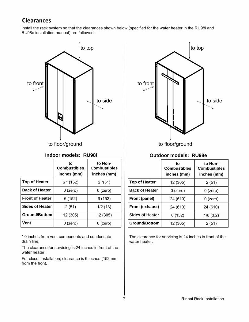
Clearances
Install the rack system so that the clearances shown below (specified for the water heater in the RU98i and RU98e installation manual) are followed.
to Combustibles inches (mm)
to Non-Combustibles inches (mm)
Top of Heater 6 * (152) 2 *(51)
Back of Heater 0 (zero) 0 (zero)
Front of Heater 6 (152) 6 (152)
Sides of Heater 2 (51) 1/2 (13)
Ground/Bottom 12 (305) 12 (305)
Vent 0 (zero) 0 (zero)
* 0 inches from vent components and condensate drain line. The clearance for servicing is 24 inches in front of the water heater. For closet installation, clearance is 6 inches (152 mm from the front.
Indoor models: RU98i to
Combustibles inches (mm)
to Non-Combustibles inches (mm)
Top of Heater 12 (305) 2 (51)
Back of Heater 0 (zero) 0 (zero)
Front (panel) 24 (610) 0 (zero)
Front (exhaust) 24 (610) 24 (610)
Sides of Heater 6 (152) 1/8 (3.2)
Ground/Bottom 12 (305) 2 (51)
Outdoor models: RU98e
The clearance for servicing is 24 inches in front of the water heater.
to side
to front
to top
to floor/ground
to side
to front
to top
to floor/ground
8 Rinnai Rack Installation
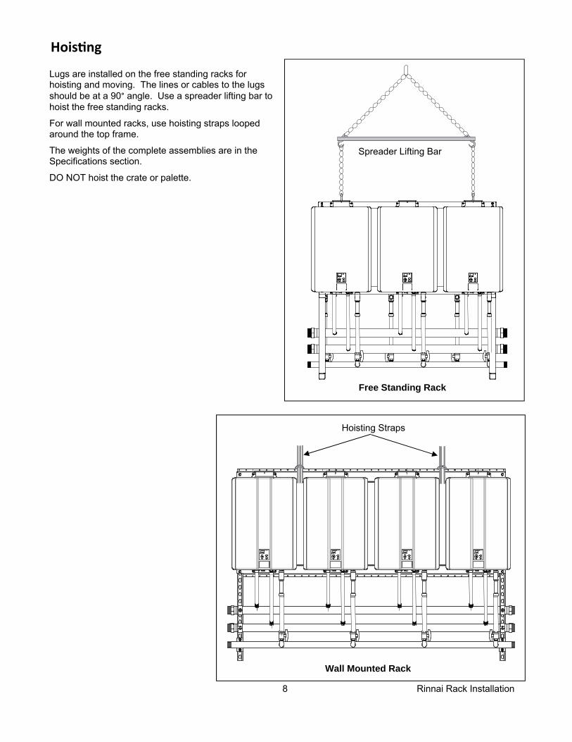
Hois ng
Lugs are installed on the free standing racks for hoisting and moving. The lines or cables to the lugs should be at a 90° angle. Use a spreader lifting bar to hoist the free standing racks.
For wall mounted racks, use hoisting straps looped around the top frame.
The weights of the complete assemblies are in the Specifications section.
DO NOT hoist the crate or palette.
Free Standing Rack
Spreader Lifting Bar
Wall Mounted Rack
Hoisting Straps
9 Rinnai Rack Installation
Moun ng Wall Racks
1. Iden fy the installa on loca on and confirm that the installa on will meet all required clearances.
2. Securely a ach the rack to the wall. Ensure that the a achment strength is sufficient to support the weight. Refer to the weight in the Specifica ons sec on. Use a leveling tool to ensure that the water heater is level. Proper opera on requires that the water heater be level. The rack / water heaters should be installed in an upright posi on. Do not install upside down or on its side.
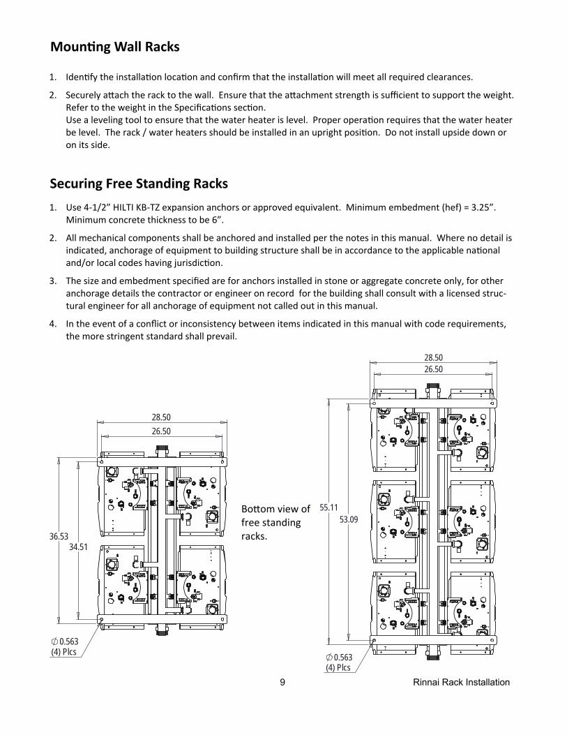
Securing Free Standing Racks
28.50 26.50
53.09
0.563(4) Plcs
55.11
26.50 28.50
36.53 34.51
0.563(4) Plcs
1. Use 4‐1/2” HILTI KB‐TZ expansion anchors or approved equivalent. Minimum embedment (hef) = 3.25”. Minimum concrete thickness to be 6”.
2. All mechanical components shall be anchored and installed per the notes in this manual. Where no detail is indicated, anchorage of equipment to building structure shall be in accordance to the applicable na onal and/or local codes having jurisdic on.
3. The size and embedment specified are for anchors installed in stone or aggregate concrete only, for other anchorage details the contractor or engineer on record for the building shall consult with a licensed struc‐tural engineer for all anchorage of equipment not called out in this manual.
4. In the event of a conflict or inconsistency between items indicated in this manual with code requirements, the more stringent standard shall prevail.
Bo om view of free standing racks.
10 Rinnai Rack Installation
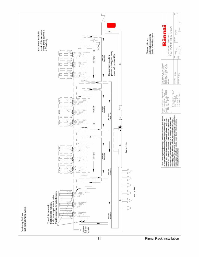
Piping for Mul ple Racks
Mul ple rack systems should be installed in parallel using a secondary manifold from the building cold and hot water supply. Reference the drawing for guidance.
A low pressure gas regulator must be installed prior to the rack system. Note the maximum cumula ve input for the system when sizing the gas regulator.
Use common plumbing prac ce and reference all applicable codes when sizing the secondary manifolds and gas regulator.
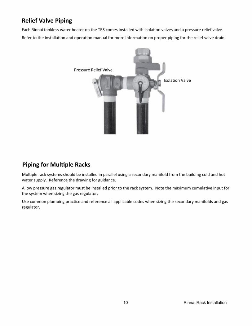
Relief Valve Piping Each Rinnai tankless water heater on the TRS comes installed with Isola on valves and a pressure relief valve.
Refer to the installa on and opera on manual for more informa on on proper piping for the relief valve drain.
Isola on Valve
Pressure Relief Valve
11 Rinnai Rack Installation
12 Rinnai Rack Installation
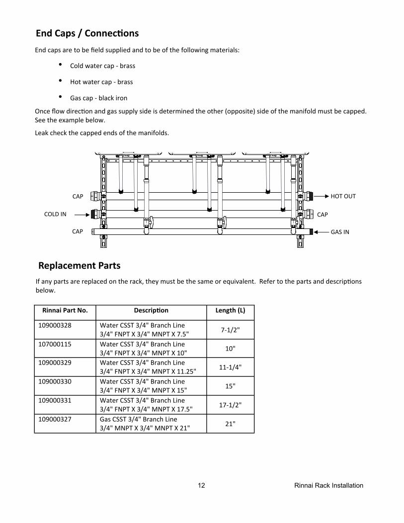
End Caps / Connec ons
End caps are to be field supplied and to be of the following materials:
• Cold water cap ‐ brass
• Hot water cap ‐ brass
• Gas cap ‐ black iron
Once flow direc on and gas supply side is determined the other (opposite) side of the manifold must be capped. See the example below.
Leak check the capped ends of the manifolds.
COLD IN
HOT OUT
GAS IN
CAP
CAP
CAP
Replacement Parts
If any parts are replaced on the rack, they must be the same or equivalent. Refer to the parts and descrip ons below.
Rinnai Part No. Descrip on Length (L)
109000328 Water CSST 3/4" Branch Line 3/4" FNPT X 3/4" MNPT X 7.5" 7‐1/2"
109000329 Water CSST 3/4" Branch Line 3/4" FNPT X 3/4" MNPT X 11.25" 11‐1/4"
109000330 Water CSST 3/4" Branch Line 3/4" FNPT X 3/4" MNPT X 15" 15"
109000331 Water CSST 3/4" Branch Line 3/4" FNPT X 3/4" MNPT X 17.5" 17‐1/2"
109000327 Gas CSST 3/4" Branch Line 3/4" MNPT X 3/4" MNPT X 21" 21"
107000115 Water CSST 3/4" Branch Line 3/4" FNPT X 3/4" MNPT X 10" 10"
13 Rinnai Rack Installation
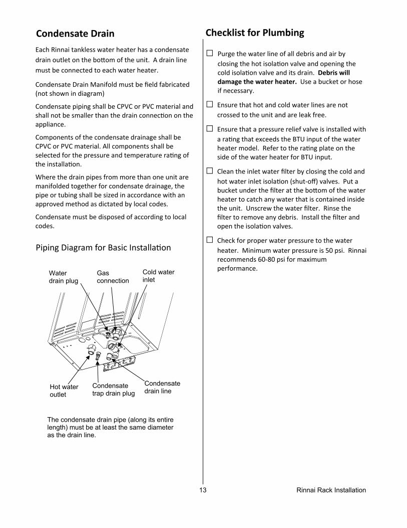
Condensate Drain
Each Rinnai tankless water heater has a condensate drain outlet on the bo om of the unit. A drain line must be connected to each water heater.
Condensate Drain Manifold must be field fabricated (not shown in diagram)
Condensate piping shall be CPVC or PVC material and shall not be smaller than the drain connec on on the appliance.
Components of the condensate drainage shall be CPVC or PVC material. All components shall be selected for the pressure and temperature ra ng of the installa on.
Where the drain pipes from more than one unit are manifolded together for condensate drainage, the pipe or tubing shall be sized in accordance with an approved method as dictated by local codes.
Condensate must be disposed of according to local codes.
Water drain plug
Condensate trap drain plug
Condensate drain line
Gas connection
Cold water inlet
Hot water outlet
The condensate drain pipe (along its entire length) must be at least the same diameter as the drain line.
Piping Diagram for Basic Installa on
Checklist for Plumbing
□ Purge the water line of all debris and air by closing the hot isola on valve and opening the cold isola on valve and its drain. Debris will damage the water heater. Use a bucket or hose if necessary.
□ Ensure that hot and cold water lines are not crossed to the unit and are leak free.
□ Ensure that a pressure relief valve is installed with a ra ng that exceeds the BTU input of the water heater model. Refer to the ra ng plate on the side of the water heater for BTU input.
□ Clean the inlet water filter by closing the cold and hot water inlet isola on (shut‐off) valves. Put a bucket under the filter at the bo om of the water heater to catch any water that is contained inside the unit. Unscrew the water filter. Rinse the filter to remove any debris. Install the filter and open the isola on valves.
□ Check for proper water pressure to the water heater. Minimum water pressure is 50 psi. Rinnai recommends 60‐80 psi for maximum performance.
14 Rinnai Rack Installation
Installa on of Gas Supply
MUST DO • Check the type of gas and the gas inlet pressure
before connec ng the water heater. If the water heater is not of the gas type that the building is supplied with, DO NOT connect the water heater. Contact the dealer for the proper unit to match the gas type.
• Check the gas supply pressure immediately up‐stream at a loca on provided by the gas company. Supplied gas pressure must be within the limits shown in the Specifica ons sec on with all gas ap‐pliances opera ng.
• Before placing the appliance in opera on all joints including the heater must be checked for gas ght‐ness by means of leak detector solu on, soap and water, or an equivalent nonflammable solu on, as applicable. (Since some leak test solu ons, includ‐ing soap and water, may cause corrosion or stress cracking, the piping shall be rinsed with water a er tes ng, unless it has been determined that the leak test solu on is non‐corrosive.)
• Use approved connectors to connect the unit to the gas line. Purge the gas line of any debris before connec on to the water heater.
• Any compound used on the threaded joint of the gas piping shall be a type which resists the ac on of liquefied petroleum gas (propane / LPG).
• The gas supply line shall be gas ght, sized, and so installed as to provide a supply of gas sufficient to meet the maximum demand of the heater and all other gas consuming appliances at the loca on without loss of pressure.
WARNING 1. If you are not knowledgeable or qualified to
install gas lines or connec ons, then contact a licensed professional to install the gas supply.
2. Turn off 120v power supply.
3. Turn off the gas.
4. Gas is flammable. Do not smoke or provide other igni on sources while working with gas.
5. Do not turn on the water heater or gas un l all fumes are gone.
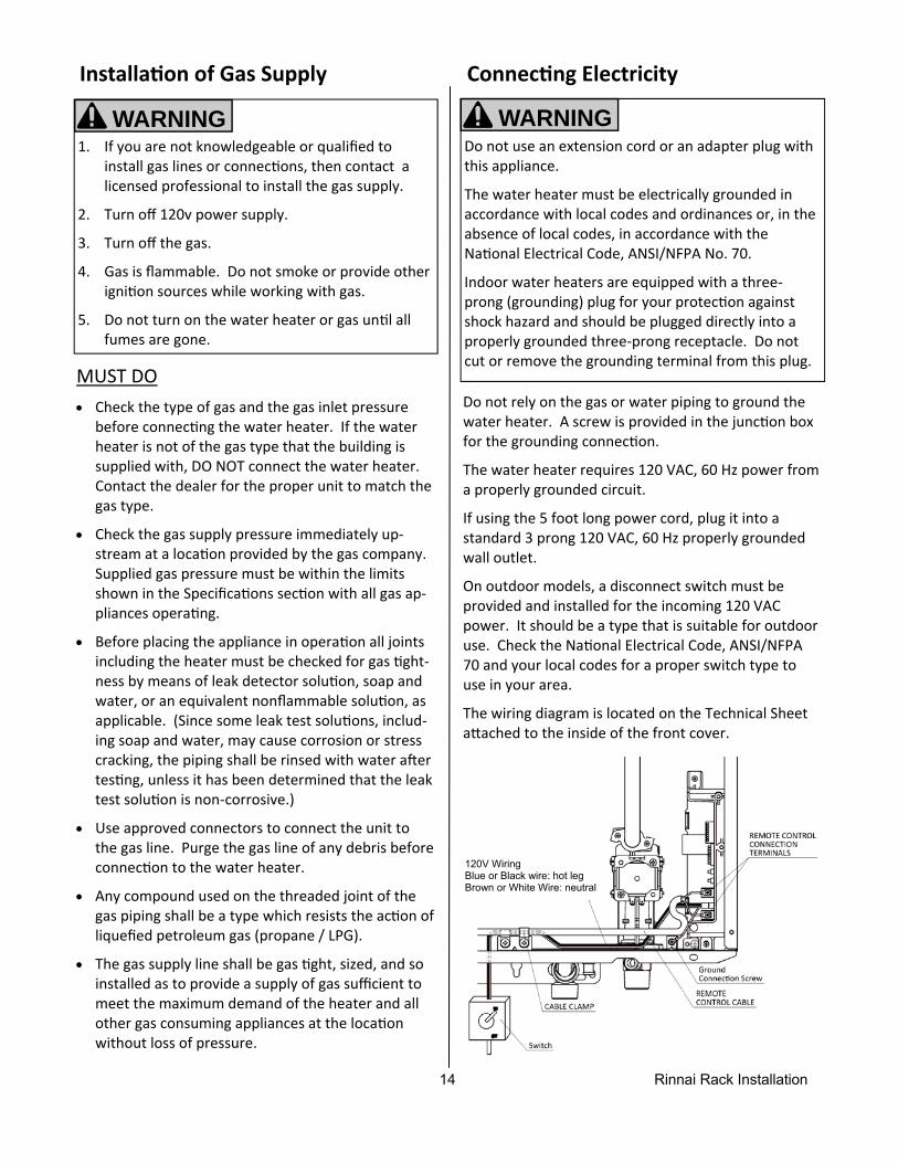
Connec ng Electricity
Do not rely on the gas or water piping to ground the water heater. A screw is provided in the junc on box for the grounding connec on.
The water heater requires 120 VAC, 60 Hz power from a properly grounded circuit.
If using the 5 foot long power cord, plug it into a standard 3 prong 120 VAC, 60 Hz properly grounded wall outlet.
On outdoor models, a disconnect switch must be provided and installed for the incoming 120 VAC power. It should be a type that is suitable for outdoor use. Check the Na onal Electrical Code, ANSI/NFPA 70 and your local codes for a proper switch type to use in your area.
The wiring diagram is located on the Technical Sheet a ached to the inside of the front cover.
WARNING Do not use an extension cord or an adapter plug with this appliance.
The water heater must be electrically grounded in accordance with local codes and ordinances or, in the absence of local codes, in accordance with the Na onal Electrical Code, ANSI/NFPA No. 70.
Indoor water heaters are equipped with a three‐prong (grounding) plug for your protec on against shock hazard and should be plugged directly into a properly grounded three‐prong receptacle. Do not cut or remove the grounding terminal from this plug.
120V Wiring Blue or Black wire: hot leg Brown or White Wire: neutral
15 Rinnai Rack Installation
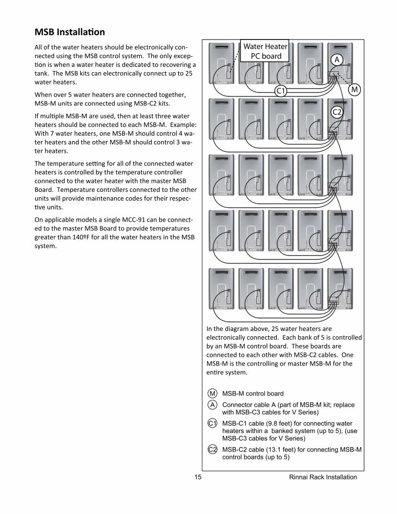
MSB Installa on
All of the water heaters should be electronically con‐nected using the MSB control system. The only excep‐
on is when a water heater is dedicated to recovering a tank. The MSB kits can electronically connect up to 25 water heaters.
When over 5 water heaters are connected together, MSB‐M units are connected using MSB‐C2 kits.
If mul ple MSB‐M are used, then at least three water heaters should be connected to each MSB‐M. Example: With 7 water heaters, one MSB‐M should control 4 wa‐ter heaters and the other MSB‐M should control 3 wa‐ter heaters.
The temperature se ng for all of the connected water heaters is controlled by the temperature controller connected to the water heater with the master MSB Board. Temperature controllers connected to the other units will provide maintenance codes for their respec‐
ve units.
On applicable models a single MCC‐91 can be connect‐ed to the master MSB Board to provide temperatures greater than 140ºF for all the water heaters in the MSB system.
M MSB-M control board
A Connector cable A (part of MSB-M kit; replace with MSB-C3 cables for V Series)
C1 MSB-C1 cable (9.8 feet) for connecting water heaters within a banked system (up to 5), (use MSB-C3 cables for V Series)
C2 MSB-C2 cable (13.1 feet) for connecting MSB-M control boards (up to 5)
In the diagram above, 25 water heaters are electronically connected. Each bank of 5 is controlled by an MSB‐M control board. These boards are connected to each other with MSB‐C2 cables. One MSB‐M is the controlling or master MSB‐M for the en re system.
M
A
C2
C1
Water HeaterPC board
16 Rinnai Rack Installation
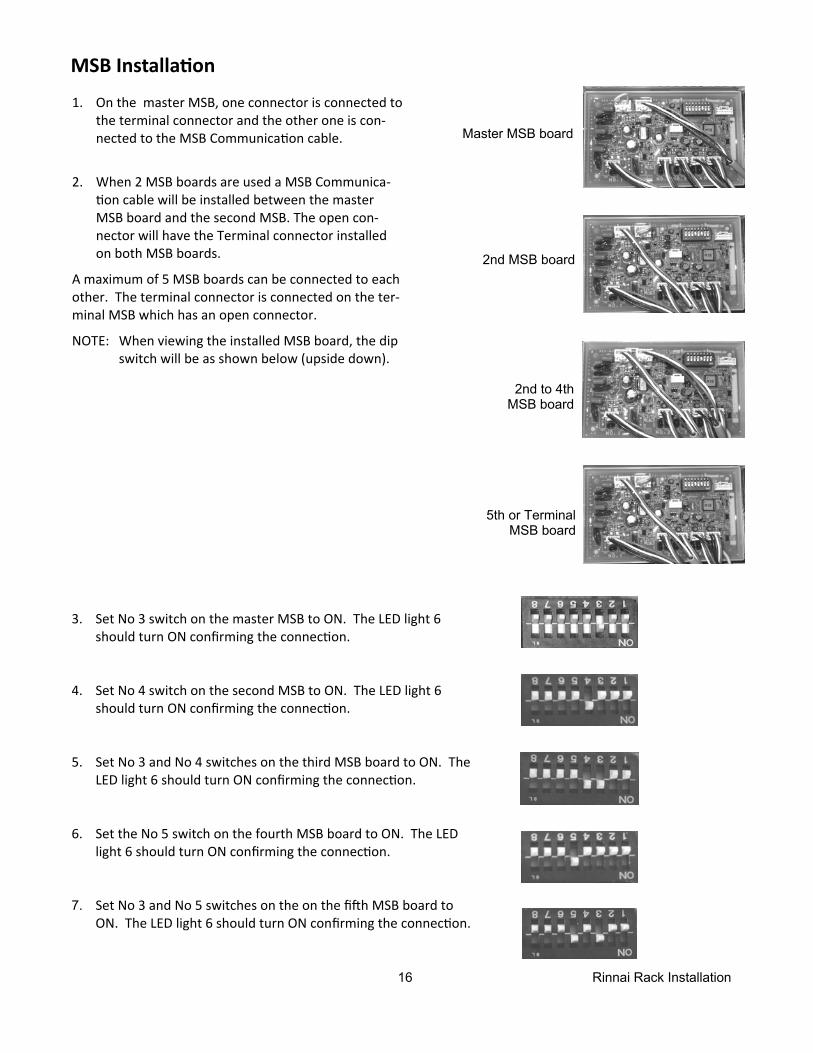
1. On the master MSB, one connector is connected to the terminal connector and the other one is con‐nected to the MSB Communica on cable.
2. When 2 MSB boards are used a MSB Communica‐on cable will be installed between the master
MSB board and the second MSB. The open con‐nector will have the Terminal connector installed on both MSB boards.
A maximum of 5 MSB boards can be connected to each other. The terminal connector is connected on the ter‐minal MSB which has an open connector.
NOTE: When viewing the installed MSB board, the dip switch will be as shown below (upside down).
MSB Installa on
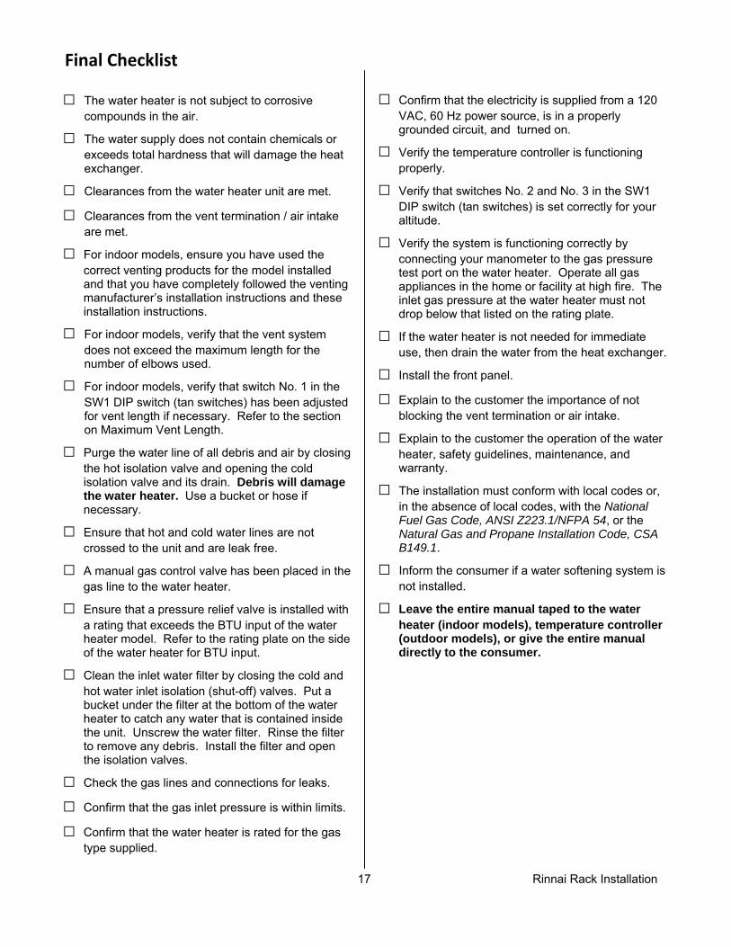
3. Set No 3 switch on the master MSB to ON. The LED light 6 should turn ON confirming the connec on.
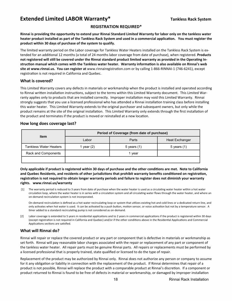
4. Set No 4 switch on the second MSB to ON. The LED light 6 should turn ON confirming the connec on.
5. Set No 3 and No 4 switches on the third MSB board to ON. The LED light 6 should turn ON confirming the connec on.
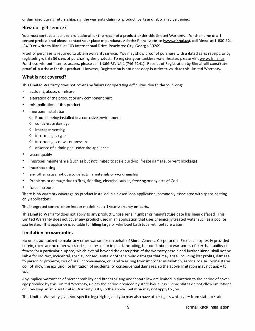
6. Set the No 5 switch on the fourth MSB board to ON. The LED light 6 should turn ON confirming the connec on.
7. Set No 3 and No 5 switches on the on the fi h MSB board to ON. The LED light 6 should turn ON confirming the connec on.
Master MSB board
2nd MSB board
2nd to 4th MSB board
5th or Terminal MSB board
17 Rinnai Rack Installation
Final Checklist
□ The water heater is not subject to corrosive compounds in the air.
□ The water supply does not contain chemicals or exceeds total hardness that will damage the heat exchanger.
□ Clearances from the water heater unit are met.
□ Clearances from the vent termination / air intake are met.
□ For indoor models, ensure you have used the correct venting products for the model installed and that you have completely followed the venting manufacturer’s installation instructions and these installation instructions.
□ For indoor models, verify that the vent system does not exceed the maximum length for the number of elbows used.
□ For indoor models, verify that switch No. 1 in the SW1 DIP switch (tan switches) has been adjusted for vent length if necessary. Refer to the section on Maximum Vent Length.
□ Purge the water line of all debris and air by closing the hot isolation valve and opening the cold isolation valve and its drain. Debris will damage the water heater. Use a bucket or hose if necessary.
□ Ensure that hot and cold water lines are not crossed to the unit and are leak free.
□ A manual gas control valve has been placed in the gas line to the water heater.
□ Ensure that a pressure relief valve is installed with a rating that exceeds the BTU input of the water heater model. Refer to the rating plate on the side of the water heater for BTU input.
□ Clean the inlet water filter by closing the cold and hot water inlet isolation (shut-off) valves. Put a bucket under the filter at the bottom of the water heater to catch any water that is contained inside the unit. Unscrew the water filter. Rinse the filter to remove any debris. Install the filter and open the isolation valves.
□ Check the gas lines and connections for leaks.
□ Confirm that the gas inlet pressure is within limits.
□ Confirm that the water heater is rated for the gas type supplied.
□ Confirm that the electricity is supplied from a 120 VAC, 60 Hz power source, is in a properly grounded circuit, and turned on.
□ Verify the temperature controller is functioning properly.
□ Verify that switches No. 2 and No. 3 in the SW1 DIP switch (tan switches) is set correctly for your altitude.
□ Verify the system is functioning correctly by connecting your manometer to the gas pressure test port on the water heater. Operate all gas appliances in the home or facility at high fire. The inlet gas pressure at the water heater must not drop below that listed on the rating plate.
□ If the water heater is not needed for immediate use, then drain the water from the heat exchanger.
□ Install the front panel.
□ Explain to the customer the importance of not blocking the vent termination or air intake.
□ Explain to the customer the operation of the water heater, safety guidelines, maintenance, and warranty.
□ The installation must conform with local codes or, in the absence of local codes, with the National Fuel Gas Code, ANSI Z223.1/NFPA 54, or the Natural Gas and Propane Installation Code, CSA B149.1.
□ Inform the consumer if a water softening system is not installed.
□ Leave the entire manual taped to the water heater (indoor models), temperature controller (outdoor models), or give the entire manual directly to the consumer.
18 Rinnai Rack Installation
Extended Limited LABOR Warranty* Tankless Rack System
REGISTRATION REQUIRED*
Rinnai is providing the opportunity to extend your Rinnai Standard Limited Warranty for labor only on the tankless water heater product installed as part of the Tankless Rack System and used in a commercial applica on. You must register the product within 30 days of purchase of the system to qualify.
The limited warranty period on the Labor coverage for Tankless Water Heaters installed on the Tankless Rack System is ex‐tended for an addi onal 12 months (a total of 24 months labor coverage from date of purchase), when registered. Products not registered will s ll be covered under the Rinnai standard product limited warranty as provided in the Opera ng In-struc on manual which comes with the Tankless water heater. Warranty informa on is also available on Rinnai's web site at www.rinnai.us. You can register at www.rinnairegistra on.com or by calling 1‐866‐RINNAI‐1 (746‐6241), except registra on is not required in California and Quebec.
What is covered? This Limited Warranty covers any defects in materials or workmanship when the product is installed and operated according to Rinnai wri en installa on instruc ons, subject to the terms within this Limited Warranty document. This Limited War‐ranty applies only to products that are installed correctly. Improper installa on may void this Limited Warranty. Rinnai strongly suggests that you use a licensed professional who has a ended a Rinnai installa on training class before installing this water heater. This Limited Warranty extends to the original purchaser and subsequent owners, but only while the product remains at the site of the original installa on. This Limited Warranty only extends through the first installa on of the product and terminates if the product is moved or reinstalled at a new loca on.
How long does coverage last?
Only applicable if product is registered within 30 days of purchase and the other condi ons are met. Note to California and Quebec Residents, and residents of other jurisdic ons that prohibit warranty benefits condi oned on registra on, registra on is not required to obtain longer warranty periods and failure to register does not diminish your warranty rights. www.rinnai.us/warranty
[1] The warranty period is reduced to 3 years from date of purchase when the water heater is used as a circula ng water heater within a hot water circula on loop, where the water heater is in series with a circula on system and all circula ng water flows through the water heater, and where an on‐demand recircula on system is not incorporated.
On‐demand recircula on is defined as a hot water recircula ng loop or system that u lizes exis ng hot and cold lines or a dedicated return line, and only ac vates when hot water is used. It can be ac vated by a push bu on, mo on sensor, or voice ac va on but not by a temperature sensor. A
mer added to a standard recircula ng pump is not considered as on‐demand.
[2] Labor coverage is extended to 5 years in residen al applica ons and to 2 years in commercial applica ons if the product is registered within 30 days (except registra on is not required in California and Quebec) and/or if the other condi ons above in the Residen al Applica ons and Commercial Applica ons sec ons are sa sfied.
What will Rinnai do? Rinnai will repair or replace the covered product or any part or component that is defec ve in materials or workmanship as set forth. Rinnai will pay reasonable labor charges associated with the repair or replacement of any part or component of the tankless water heater. All repair parts must be genuine Rinnai parts. All repairs or replacements must be performed by a licensed professional that is properly trained, state qualified or licensed to do the type of repair.
Replacement of the product may be authorized by Rinnai only. Rinnai does not authorize any person or company to assume for it any obliga on or liability in connec on with the replacement of the product. If Rinnai determines that repair of a product is not possible, Rinnai will replace the product with a comparable product at Rinnai’s discre on. If a component or product returned to Rinnai is found to be free of defects in material or workmanship, or damaged by improper installa on
Item Period of Coverage (from date of purchase)
Labor Parts Heat Exchanger
Tankless Water Heaters 1 year (2) 5 years (1) 5 years (1)
Rack and Components 1 year
19 Rinnai Rack Installation
or damaged during return shipping, the warranty claim for product, parts and labor may be denied.
How do I get service? You must contact a licensed professional for the repair of a product under this Limited Warranty. For the name of a li‐censed professional please contact your place of purchase, visit the Rinnai website (www.rinnai.us), call Rinnai at 1‐800‐621‐9419 or write to Rinnai at 103 Interna onal Drive, Peachtree City, Georgia 30269.
Proof of purchase is required to obtain warranty service. You may show proof of purchase with a dated sales receipt, or by registering within 30 days of purchasing the product. To register your tankless water heater, please visit www.rinnai.us. For those without internet access, please call 1‐866‐RINNAI1 (746‐6241). Receipt of Registra on by Rinnai will cons tute proof‐of‐purchase for this product. However, Registra on is not necessary in order to validate this Limited Warranty.
What is not covered? This Limited Warranty does not cover any failures or opera ng difficul es due to the following:
• accident, abuse, or misuse
• altera on of the product or any component part
• misapplica on of this product
• improper installa on ◊ Product being installed in a corrosive environment ◊ condensate damage ◊ improper ven ng ◊ incorrect gas type ◊ incorrect gas or water pressure ◊ absence of a drain pan under the appliance
• water quality
• improper maintenance (such as but not limited to scale build‐up, freeze damage, or vent blockage)
• incorrect sizing
• any other cause not due to defects in materials or workmanship
• Problems or damage due to fires, flooding, electrical surges, freezing or any acts of God.
• force majeure There is no warranty coverage on product installed in a closed loop applica on, commonly associated with space hea ng only applica ons.
The integrated controller on indoor models has a 1 year warranty on parts.
This Limited Warranty does not apply to any product whose serial number or manufacture date has been defaced. This Limited Warranty does not cover any product used in an applica on that uses chemically treated water such as a pool or spa heater. This appliance is suitable for filling large or whirlpool bath tubs with potable water.
Limita on on warran es No one is authorized to make any other warran es on behalf of Rinnai America Corpora on. Except as expressly provided herein, there are no other warran es, expressed or implied, including, but not limited to warran es of merchantability or fitness for a par cular purpose, which extend beyond the descrip on of the warranty herein and further Rinnai shall not be liable for indirect, incidental, special, consequen al or other similar damages that may arise, including lost profits, damage to person or property, loss of use, inconvenience, or liability arising from improper installa on, service or use. Some states do not allow the exclusion or limita on of incidental or consequen al damages, so the above limita on may not apply to you.
Any implied warran es of merchantability and fitness arising under state law are limited in dura on to the period of cover‐age provided by this Limited Warranty, unless the period provided by state law is less. Some states do not allow limita ons on how long an implied Limited Warranty lasts, so the above limita on may not apply to you.
This Limited Warranty gives you specific legal rights, and you may also have other rights which vary from state to state.
20 Rinnai Rack Installation 100000294
8/2012
Recommended