FIELD INSPECTION AND TEST PROCEDURE
*note: this is the sample document for the related job only
*author: [email protected]
TABLE OF CONTENTS
1. Scope
2. Applicable Code, Standard And Specification
3. General
4. Material Inspection
4.1 Material Receiving Inspection
5. Material Traceability Control
5.1 Extent of Traceability Control
6. Dimensional Inspection
6.1 Foundation Receiving Inspection
6.2 Location Mark Check
6.3 Fit-up Inspection
6.4 Roundness
6.5 Plumbness
6.6 Local Deviation
7. Nondestructive Examination
7.1 Visual Inspection
7.2 NDE Procedure
7.3 Radiographic Examination (RT)
7.4 Liquid Penetrant Examination (PT)
7.5 Vacuum Box Test (VBT)
7.6 Pneumatic Leak Test (LT)

7.7 Repair and Re-examination
8. Hydrostatic Test
8.1 Pre-test Check
8.2 Water Filling
8.3 Settlement Monitoring
8.4 Hydrostatic Test
8.5 Cleaning
8.6 Hydrostatic Test for Heating Coil
9. Fixed Roof Test
10. Paint Inspection
11. Tank Calibration
12. Final Inspection
13. Witness Inspection
14. Manufacturer’s Data Report
1. Scope
This document covers the inspection and test requirements of storage tanks at the construction site specified for the Two (2) nos additional PSR-2 Crude storage tank at Petronas Penapisan Melaka. (PPM)
2. Applicable Code, Standard And Specification
The following standards, code, and specifications have been used as a source of information in the preparation of this document.
API Standard
API 650-9th Ed. 1995 : Welded Steel Tanks for Oil Storage
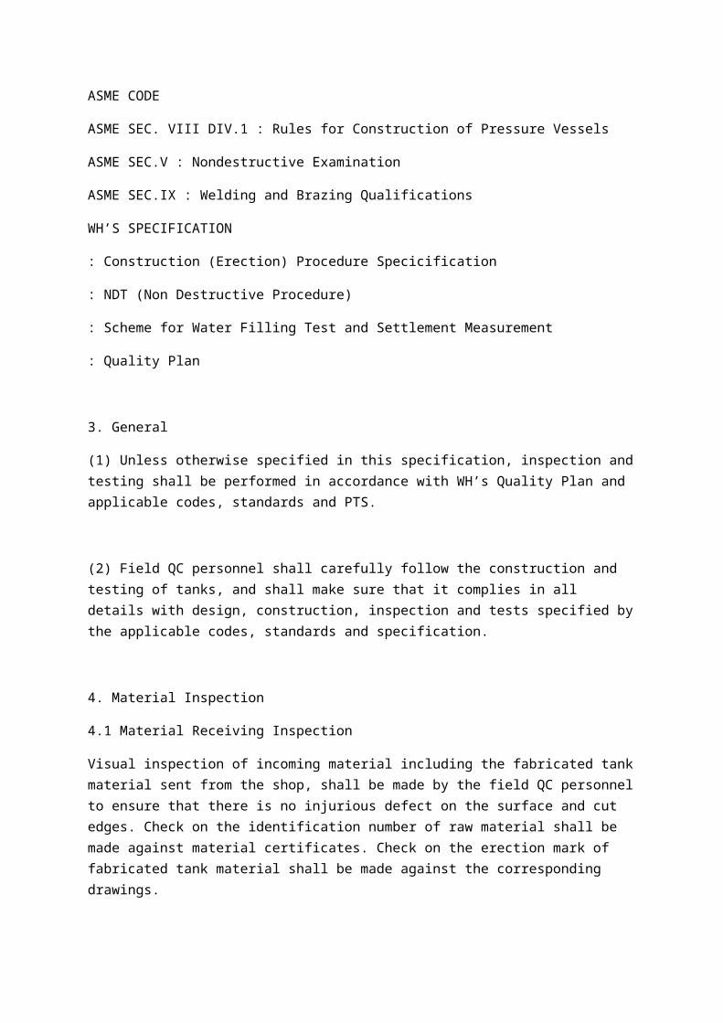
ASME CODE
ASME SEC. VIII DIV.1 : Rules for Construction of Pressure Vessels
ASME SEC.V : Nondestructive Examination
ASME SEC.IX : Welding and Brazing Qualifications
WH’S SPECIFICATION
: Construction (Erection) Procedure Specicification
: NDT (Non Destructive Procedure)
: Scheme for Water Filling Test and Settlement Measurement
: Quality Plan
3. General
(1) Unless otherwise specified in this specification, inspection and testing shall be performed in accordance with WH’s Quality Plan and applicable codes, standards and PTS.
(2) Field QC personnel shall carefully follow the construction and testing of tanks, and shall make sure that it complies in all details with design, construction, inspection and tests specified by the applicable codes, standards and specification.
4. Material Inspection
4.1 Material Receiving Inspection
Visual inspection of incoming material including the fabricated tank material sent from the shop, shall be made by the field QC personnel to ensure that there is no injurious defect on the surface and cut edges. Check on the identification number of raw material shall be made against material certificates. Check on the erection mark of fabricated tank material shall be made against the corresponding drawings.
5. Material Traceability Control
5.1 Extent of Traceability Control
The following tank components are required to be traceable against the material certificate. The As-built Sketch shall be prepared upon completion of the erection.
a. Shell Plate
Coded marking made at shop can be used to identify the material and be recorded in As-built Sketch. As-build Sketch may be supported by the related material identification records sent from shop.
6. Dimensional Inspection
6.1 Foundation Receiving Inspection
All the stage of receiving tank foundation, the field QC personnel shall review the foundation inspection report. Spot check of actual dimension and bench mark shall be made against the report.
6.2 Location Mark Check
Prior to the primary laying-down or erection of Bottom Plate, Bottom Sketch Plate, Shell Plate, Roof Structures and Roof Plate, the field QC personnel shall check the location marking in accordance with the related orientation drawings. Similarly, prior to make the Nozzle/Manhole opening, the location marking of opening shall be ensured.
6.3 Fit-up Inspection
Weld preparation and dimensional accuracy shall be checked prior to start welding. Butt welds of Shell joints shall be matched accurately and retained in position during welding operation.
Misalignment of Shell weld joint shall not exceed the following tolerance.
a. In completed shell vertical joint
Shell Plate 15.8 mm thk : 1.6 mm
b. In completed shell horizonttal joint
Upper Plate 15.8 mm thk : 1.6 mm
For Bottom Annular butt weld, the tolerances of vertical joints shall be applied.
6.4 Roundness
Prior to commencement of shell to Bottom Sketch plate weld, the tank internal radius shall be measured. The horizontally measured tank radius at 300 mm above the bottom corner weld shall not exceed the following tolerances.
Tank < 12 m diameter : + 13 mm 6.5 Plumbness The first course shell plate shall be checked for plumbness, level and roundness before welding in accordance with WH’s construction procedure to ensure that the tank will be completed within the specified dimensional tolerances. Plumbness of Shell shall be inspected after completion of all Shell welds. The out-of plumbness shall not exceed 1/200 of the total tank height. 6.6 Local Deviation Local deviation shall be inspected, if there is any noticeable distortion after completion of shell weld. The Local deviation shall not exceed the tolerance of 13 mm. 6.7 All nozzle and couplings directly connected with piping shall be at the
correct elevations from the surface of bottom plate and radial positions after completion of welding and erection and remain at the following tolerance. Elevation of nozzle : + 10 mm Radial position of nozzle : + 15 mm Nozzle projection : + 10 mm Inclination of flange face : + 0.5°
7. Nondestructive Examination
7.1 Visual Inspection
Regardless any other nondestructive inspection method applied, all the site welds shall be subjected to visual inspection, and meet the requirements of API 650 Sec. 6 para 6.5.
7.2 NDE Procedure
General requirements, examiner’s qualification, equipment and operation procedure of nondestructive examination shall be in accordance with WH Specification : Nondestructive Test Procedure.
7.3 Radiographic Examination (RT)
The following RT shall be performed.
a. Shell vertical / horizontal joints and bottom annular radial joints shall be radiographed in accordance with the requirement of API 650 Sec. 6 para 6.1.
Heating coil butt joints shall be radiographed on spot basis. Minimum 5% butt joints of heating coil welded by each welder shall be fully radiographed.
b. Radiographs shall be judged in accordance with API 650 Sec. 6 para 6.1.5.
c. When a spot radiograph fail to comply with the acceptance standard, additional radiographs shall be taken in accordance with the requirement of API 650 Sec. 6 para 6.1.6.
7.4 Liquid Penetrant Examination (PT)
The following PT shall be performed.
a. The attachment welds of nozzle / manhole welded to shell at site shall be examined by PT.
b. The acceptance standard shall be in accordance with API 650 sec. 6 para 6.4.4.
7.5 Vacuum Box Test (VBT)
The following vacuum box test shall be performed.
a. All Bottom welds, i.e. Bottom-to-Bottom, Sketch Bottom Sketch-to-Bottom Sketch, Bottom Sketch-to-Shell joints, shall be inspected.
b. Any leakage observed by VBT is unacceptable.
7.6 Pneumatic Leak Test (LT)
The following pneumatic leak test shall be performed.
All attachment weld of reinforcement plate on each shell opening welded at site shall be inspected in accordance with API 650 Sec. 5 para 5.3.5. Any leakage observed by LT is unacceptable.
7.7 Repair and Re-examination
When an imperfection is judged to be repaired by welding, repair welding shall be make in accordance with the applicable welding procedure. Repaired are shall be re-examined by the same method originally used.
8. Hydrostatic Test
8.1 Pre-test Check
a. Before filling water into the tank, it shall be ensured that all inspection on Bottom, Shell and Roof including attachment welds shall be completed.
b. Any foreign articles shall not be left in the tank.
8.2 Water Filling
a. The water filling rate shall be decided with consideration given to tank size, pump facilities, water supply available, stability of foundation settlement, and other matter relating to safety.
b. When foundation settlements are negligible or significantly greater than expected settlement, water filling rate may be changed.
c. During the entire filling and emptying operation, roof manhole and/or other openings shall be kept open.
d. During the water filling, the floating roof shall be checked frequently for leaks.
8.3 Settlement Monitoring
a. Settlement reading shall be take at a minimum of 4 points around the base of tank.
b. Settlement reading shall be taken and reported to Contractor at least once a day while the tank is being filled with water and emptied.
8.4 Hydrostatic Test
a. Water shall be filled to the specified test level as WH Spec.
b. After the tank filled to test water level, all welds in the shell, including shell to bottom Sketch Plate welds, shall be visually inspected for water tightness.
c. Water shall be maintained at the test level for minimum of 24 hours after which water may be discharged.
d. Prior to starting the water discharging, ensure that the roof openings are opened.
8.5 Cleaning
a. During and after the tank is emptied, the inside of tank shall be cleaned.
b. All sand, sludge and rubbish on the tank bottom shall be removed.
8.6 Hydrostatic Test for Heating Coil
Heating coil shall be tested hydrostatically at a pressure specified in applicable drawing.
9. Fixed Roof Test
While the tank is maintained at the test water level, welds on the fixed roof shall be pneumatically leak tested. Non-pressure tank roofs shall be tested to pressure not exceeding the weight of the roof plates with compressed air and low-pressure tank roofs shall be tested to a pressure equal to the
maximum internal pressure rating. The inaccessible are during hydrostatic test shall be inspected in advance by vacuum box.
10. Paint Inspection
Paint inspection shall cover the following items.
a. paint material check
b. surface preparation check
c. paint application check
d. dry film thickness (DFT) check
e. visual inspection of completed surface
f. pinhole test for tank internal lining
The magnetic pull-off type gauge or fixed probe magnetic flux type gauge shall be used for DFT readings. For each coat of paint, the DFT shall be taken at a frequency of one measurement of every 10 square meters area. Each measurement consists of an average of three gauge readings next to one another. All spot measurements shall not be less that 100% of the specified DFT.
After the final coating has been completed, the field QC personnel shall ensure that the appropriate clean-up is done, and that any abrasions, nicks or scrapes are repaired as required.
11. Tank Calibration
Tank calibration and preparation of gauge table shall be performed by a specialized firm in accordance with internationally accepted method and with local statutory requirements.
12. Final Inspection
Prior to tank box-up, the inside of tank shall be thoroughly ensured clean. Flange surfaces of Nozzle/Manhole shall be carefully inspected for defects which may caused and leakage.
It shall be also ensured that all works required by drawings, specifications and the related inspection and test plan have been thoroughly completed.
13. Witness Inspection
The scope of inspection by Vendor, CONTRACTOR, and OWNER is indicated in Scope of Inspection. The Inspection and Test Plan shall be progressively followed by the inspector throughout site construction.
14. Manufacture’s Data Report (MDR)
The site portion of MDR shall be compiled at site as the construction is progressing. The completed site MDR shall be submitted to CONTRACTOR, while a original copy will be sent to WH home office for retaining. As a minimum, the following inspection records shall be included in the site MDR as per Quality Plan.
a. Inspection Certificate
b. As-built Sketch of Shell Plate
c. Welders Map of Shell and Bottom Plate/WPS & PQR/Welder’s Qualification Records
d. NDE Record of RT, PT, VBT and LT
e. Dimensional Inspection Record of Tank Foundation, Roundness and Plumbness
f. Hydrostatic Test Record including settlement data
g. Roof Test Record
h. Paint Inspection Record
Figure 1: Worldwide LNG imports [1]
LNG is Liquefied Natural Gas, in which the main ingredient, methane, is liquefied at the
extremely low temperature of minus 161.5 °C. Liquefied natural gas takes up 1/600th the volume
of natural gas in a gaseous state, making possible the mass transportation and storage by LNG
ships and tanks. Additionally, as natural gas emits 20-40 % less CO2 than other fossil fuels such
as petroleum and coal, it is widely considered a form of clean energy. As a result, LNG
consumption is forecast to steadily increase as seen in Figure 1, which shows the recent growth
of worldwide LNG imports.
9%Ni steel is commonly used for aboveground LNG tanks
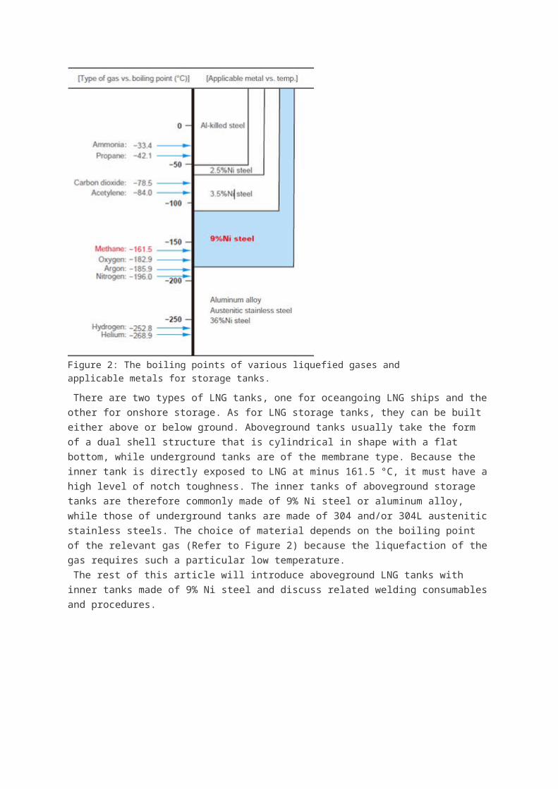
Figure 2: The boiling points of various liquefied gases and applicable metals for storage tanks.
There are two types of LNG tanks, one for oceangoing LNG ships and the other for onshore
storage. As for LNG storage tanks, they can be built either above or below ground. Aboveground
tanks usually take the form of a dual shell structure that is cylindrical in shape with a flat bottom,
while underground tanks are of the membrane type. Because the inner tank is directly exposed
to LNG at minus 161.5 °C, it must have a high level of notch toughness. The inner tanks of
aboveground storage tanks are therefore commonly made of 9% Ni steel or aluminum alloy,
while those of underground tanks are made of 304 and/or 304L austenitic stainless steels. The
choice of material depends on the boiling point of the relevant gas (Refer to Figure 2) because
the liquefaction of the gas requires such a particular low temperature.
The rest of this article will introduce aboveground LNG tanks with inner tanks made of 9% Ni
steel and discuss related welding consumables and procedures.
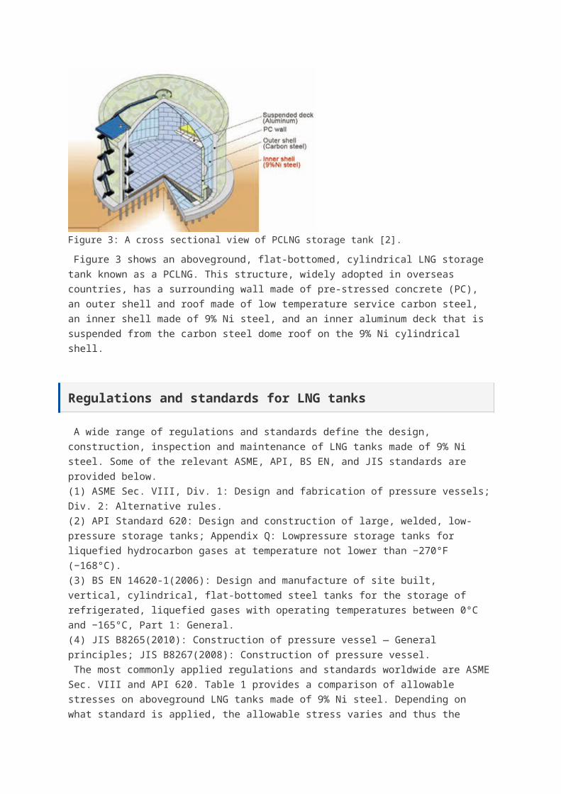
Figure 3: A cross sectional view of PCLNG storage tank [2].
Figure 3 shows an aboveground, flat-bottomed, cylindrical LNG storage tank known as a
PCLNG. This structure, widely adopted in overseas countries, has a surrounding wall made of
pre-stressed concrete (PC), an outer shell and roof made of low temperature service carbon
steel, an inner shell made of 9% Ni steel, and an inner aluminum deck that is suspended from
the carbon steel dome roof on the 9% Ni cylindrical shell.
Regulations and standards for LNG tanks
A wide range of regulations and standards define the design, construction, inspection and
maintenance of LNG tanks made of 9% Ni steel. Some of the relevant ASME, API, BS EN, and
JIS standards are provided below.
(1) ASME Sec. VIII, Div. 1: Design and fabrication of pressure vessels; Div. 2: Alternative rules.
(2) API Standard 620: Design and construction of large, welded, low-pressure storage tanks;
Appendix Q: Lowpressure storage tanks for liquefied hydrocarbon gases at temperature not
lower than −270°F (−168°C).
(3) BS EN 14620-1(2006): Design and manufacture of site built, vertical, cylindrical, flat-bottomed
steel tanks for the storage of refrigerated, liquefied gases with operating temperatures between

0°C and −165°C, Part 1: General.
(4) JIS B8265(2010): Construction of pressure vessel ― General principles; JIS B8267(2008):
Construction of pressure vessel.
The most commonly applied regulations and standards worldwide are ASME Sec. VIII and API
620. Table 1 provides a comparison of allowable stresses on aboveground LNG tanks made of
9% Ni steel. Depending on what standard is applied, the allowable stress varies and thus the
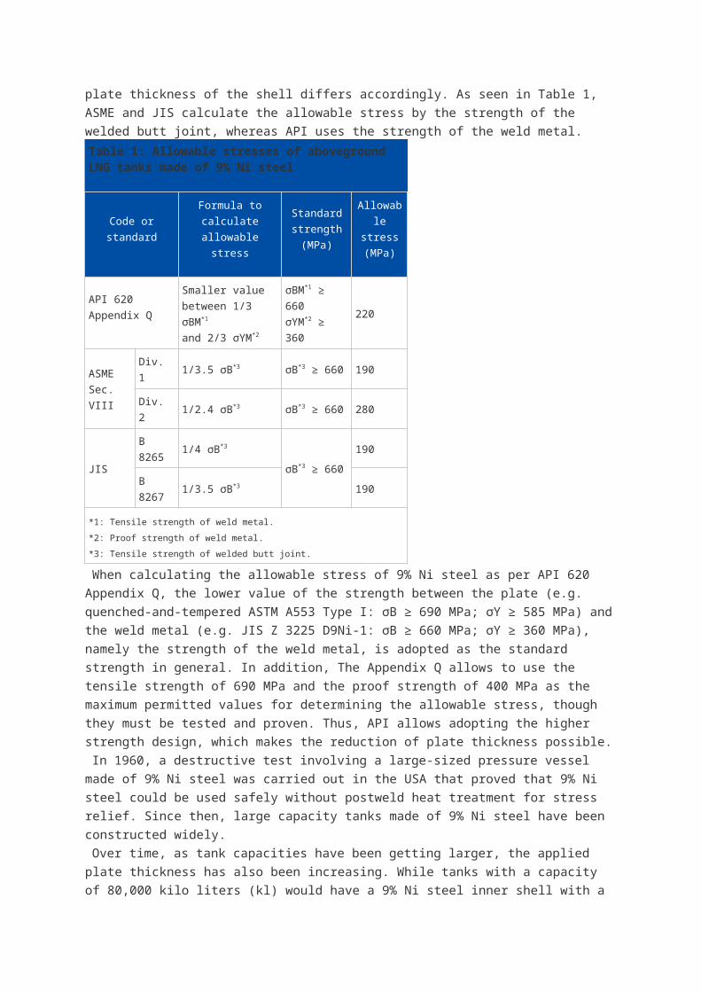
plate thickness of the shell differs accordingly. As seen in Table 1, ASME and JIS calculate the
allowable stress by the strength of the welded butt joint, whereas API uses the strength of the
weld metal.
Table 1: Allowable stresses of aboveground LNG tanks made of 9% Ni steel
Code or
standard
Formula to
calculate
allowable stress
Standard
strength
(MPa)
Allowable
stress
(MPa)
API 620
Appendix Q
Smaller value
between 1/3 σBM*1
and 2/3 σYM*2
σBM*1 ≥ 660
σYM*2 ≥ 360220
ASME
Sec. VIII
Div. 1 1/3.5 σB*3 σB*3 ≥ 660 190
Div. 2 1/2.4 σB*3 σB*3 ≥ 660 280
JISB 8265 1/4 σB*3
σB*3 ≥ 660190
B 8267 1/3.5 σB*3 190
*1: Tensile strength of weld metal.
*2: Proof strength of weld metal.
*3: Tensile strength of welded butt joint.
When calculating the allowable stress of 9% Ni steel as per API 620 Appendix Q, the lower
value of the strength between the plate (e.g. quenched-and-tempered ASTM A553 Type I: σB ≥
690 MPa; σY ≥ 585 MPa) and the weld metal (e.g. JIS Z 3225 D9Ni-1: σB ≥ 660 MPa; σY ≥ 360
MPa), namely the strength of the weld metal, is adopted as the standard strength in general. In
addition, The Appendix Q allows to use the tensile strength of 690 MPa and the proof strength of
400 MPa as the maximum permitted values for determining the allowable stress, though they
must be tested and proven. Thus, API allows adopting the higher strength design, which makes
the reduction of plate thickness possible.
In 1960, a destructive test involving a large-sized pressure vessel made of 9% Ni steel was
carried out in the USA that proved that 9% Ni steel could be used safely without postweld heat
treatment for stress relief. Since then, large capacity tanks made of 9% Ni steel have been
constructed widely.
Over time, as tank capacities have been getting larger, the applied plate thickness has also
been increasing. While tanks with a capacity of 80,000 kilo liters (kl) would have a 9% Ni steel
inner shell with a maximum plate thickness of 30 mm, 140,000 kl tanks require plate that is 40
mm thick. Currently, the design of 200,000 kl tanks is under investigation; these would require
plates with thickness of 50 mm, reaching the maximum tank capacity.
Specifications and features of 9% Ni steel
Table 2: ASTM and JIS specifications for 9% Ni steel
Standard
ASTM JIS G 3127
A353A553
Type ISL9N 520 SL9N 590
Max. plate thick. (mm) 50 50 50 100
Heat treatment NNT QT NNT QT
C (%) ≤ 0.13 ≤ 0.12
Si (%) 0.15-0.40 ≤ 0.30
Mn (%) ≤ 0.90 ≤ 0.90
P (%) ≤ 0.035 ≤ 0.025
S (%) ≤ 0.035 ≤ 0.025
Ni (%) 8.50-9.50 8.50-9.50
0.2%PS (MPa) ≥ 515 ≥ 585 ≥ 520 ≥ 590
TS (MPa) 690-825 690-830
El (%), t: Thick.(mm) ≥ 20.0≥ 21 (6 ≤ t ≤ 16) *1
≥ 25 (t > 16) *1
≥ 21 (t > 20) *2
IV (J) at −196°C ≥ 34 ≥ 34 ≥ 41
LE*3 (mm) at −196°C ≥ 0.38 -
*1: With a plate-type specimen as per JIS Z 2201 No. 5 (GL: 50 mm).
*2: With a round specimen as per JIS Z 2201 No. 4 (GL: 50 mm).
*3: Lateral expansion.
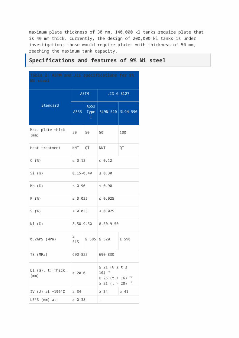
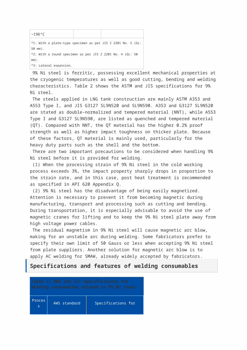
9% Ni steel is ferritic, possessing excellent mechanical properties at the cryogenic
temperatures as well as good cutting, bending and welding characteristics. Table 2 shows the
ASTM and JIS specifications for 9% Ni steel.
The steels applied in LNG tank construction are mainly ASTM A353 and A553 Type I, and JIS
G3127 SL9N520 and SL9N590. A353 and G3127 SL9N520 are stated as double-normalized and
tempered material (NNT), while A553 Type I and G3127 SL9N590, are listed as quenched and
tempered material (QT). Compared with NNT, the QT material has the higher 0.2% proof
strength as well as higher impact toughness on thicker plate. Because of these factors, QT
material is mainly used, particularly for the heavy duty parts such as the shell and the bottom.
There are two important precautions to be considered when handling 9% Ni steel before it is
provided for welding.
(1) When the processing strain of 9% Ni steel in the cold working process exceeds 3%, the
impact property sharply drops in proportion to the strain rate, and in this case, post heat
treatment is recommended as specified in API 620 Appendix Q.
(2) 9% Ni steel has the disadvantage of being easily magnetized. Attention is necessary to
prevent it from becoming magnetic during manufacturing, transport and processing such as
cutting and bending. During transportation, it is especially advisable to avoid the use of magnetic
cranes for lifting and to keep the 9% Ni steel plate away from high voltage power cables.
The residual magnetism in 9% Ni steel will cause magnetic arc blow, making for an unstable arc
during welding. Some fabricators prefer to specify their own limit of 50 Gauss or less when
accepting 9% Ni steel from plate suppliers. Another solution for magnetic arc blow is to apply AC
welding for SMAW, already widely accepted by fabricators.
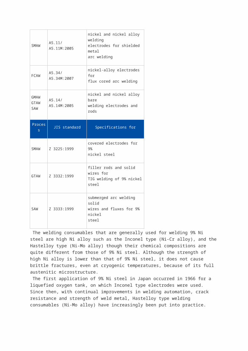
Specifications and features of welding consumables
Table 3: AWS and JIS specifications for welding consumables related to 9% Ni steel
Process AWS standard Specifications for
SMAW A5.11/A5.11M:2005
nickel and nickel alloy welding
electrodes for shielded metal
arc welding
FCAW A5.34/A5.34M:2007nickel-alloy electrodes for
flux cored arc welding
GMAW
GTAW
SAW
A5.14/A5.14M:2005nickel and nickel alloy bare
welding electrodes and rods
Process JIS standard Specifications for
SMAW Z 3225:1999covered electrodes for 9%
nickel steel
GTAW Z 3332:1999filler rods and solid wires for
TIG welding of 9% nickel steel
SAW Z 3333:1999 submerged arc welding solid
wires and fluxes for 9% nickel
steel
The welding consumables that are generally used for welding 9% Ni steel are high Ni alloy such
as the Inconel type (Ni-Cr alloy), and the Hastelloy type (Ni-Mo alloy) though their chemical
compositions are quite different from those of 9% Ni steel. Although the strength of high Ni alloy
is lower than that of 9% Ni steel, it does not cause brittle fractures, even at cryogenic
temperatures, because of its full austenitic microstructure.
The first application of 9% Ni steel in Japan occurred in 1966 for a liquefied oxygen tank, on
which Inconel type electrodes were used. Since then, with continual improvements in welding
automation, crack resistance and strength of weld metal, Hastelloy type welding consumables
(Ni-Mo alloy) have increasingly been put into practice. Molybdenum (Mo) in Hastelloy type
welding consumables has been found effective in preventing hot cracks.
AWS specifies the welding consumables for 9% Ni steel in A5.11, A5.14 and A5.34 as part of
the specifications for nickel and nickel alloy welding consumables. By contrast, JIS sets forth
specific regulations for welding consumables to be used with 9% Ni steel in Z 3225, Z 3332 and
Z 3333 as shown in Table 3. Only in regards to FCAW does JIS not directly specify the
consumables to be used with 9% Ni steel.Covered electrodes for 9% Ni steel
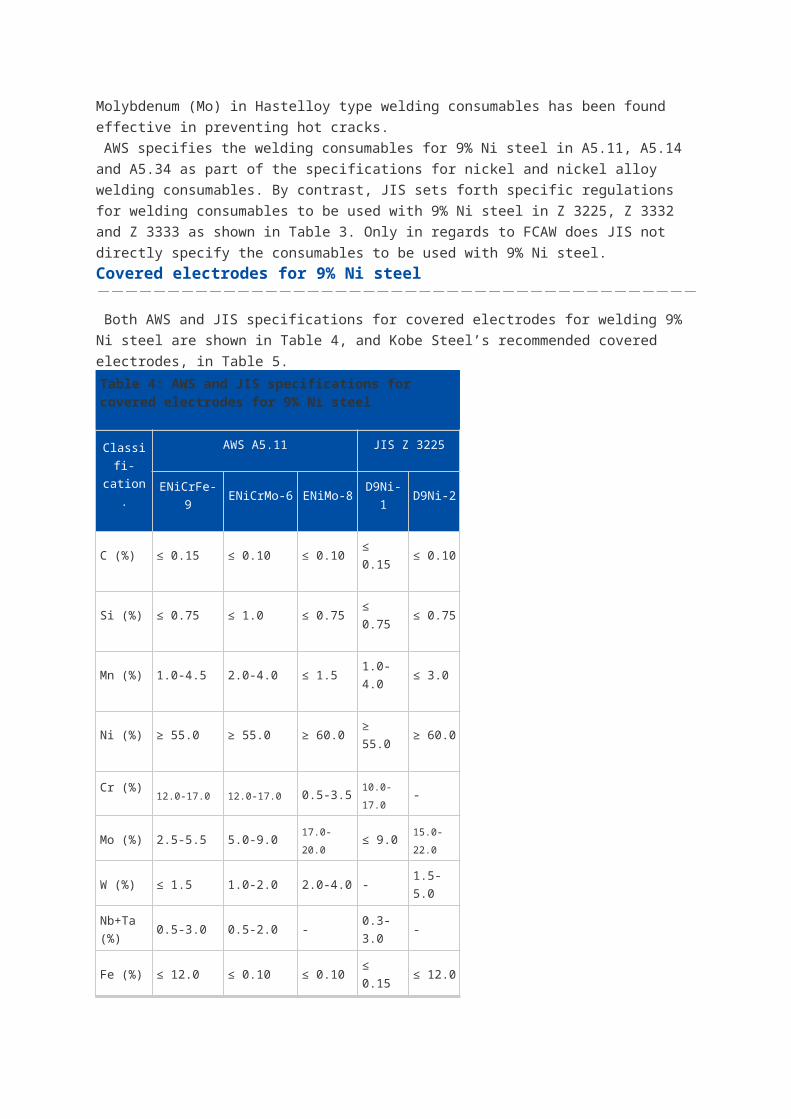
Both AWS and JIS specifications for covered electrodes for welding 9% Ni steel are shown in
Table 4, and Kobe Steel’s recommended covered electrodes, in Table 5.
Table 4: AWS and JIS specifications for covered electrodes for 9% Ni steel
Classifi-
cation.
AWS A5.11 JIS Z 3225
ENiCrFe-9 ENiCrMo-6 ENiMo-8 D9Ni-1 D9Ni-2
C (%) ≤ 0.15 ≤ 0.10 ≤ 0.10 ≤ 0.15 ≤ 0.10
Si (%) ≤ 0.75 ≤ 1.0 ≤ 0.75 ≤ 0.75 ≤ 0.75
Mn (%) 1.0-4.5 2.0-4.0 ≤ 1.5 1.0-4.0 ≤ 3.0
Ni (%) ≥ 55.0 ≥ 55.0 ≥ 60.0 ≥ 55.0 ≥ 60.0
Cr (%)12.0-17.0 12.0-17.0 0.5-3.5
10.0-
17.0-
Mo (%) 2.5-5.5 5.0-9.0 17.0-20.0 ≤ 9.015.0-
22.0
W (%) ≤ 1.5 1.0-2.0 2.0-4.0 - 1.5-5.0
Nb+Ta
(%)0.5-3.0 0.5-2.0 - 0.3-3.0 -
Fe (%) ≤ 12.0 ≤ 0.10 ≤ 0.10 ≤ 0.15 ≤ 12.0
0.2%PS
(MPa)- - - ≥ 360
TS
(MPa)≥ 650 ≥ 620 ≥ 650 ≥ 660
El (%) ≥ 25 ≥ 35 ≥ 25 ≥ 25
0IV (J)
at-196°C- - -
Av ≥ 34
Each ≥ 27
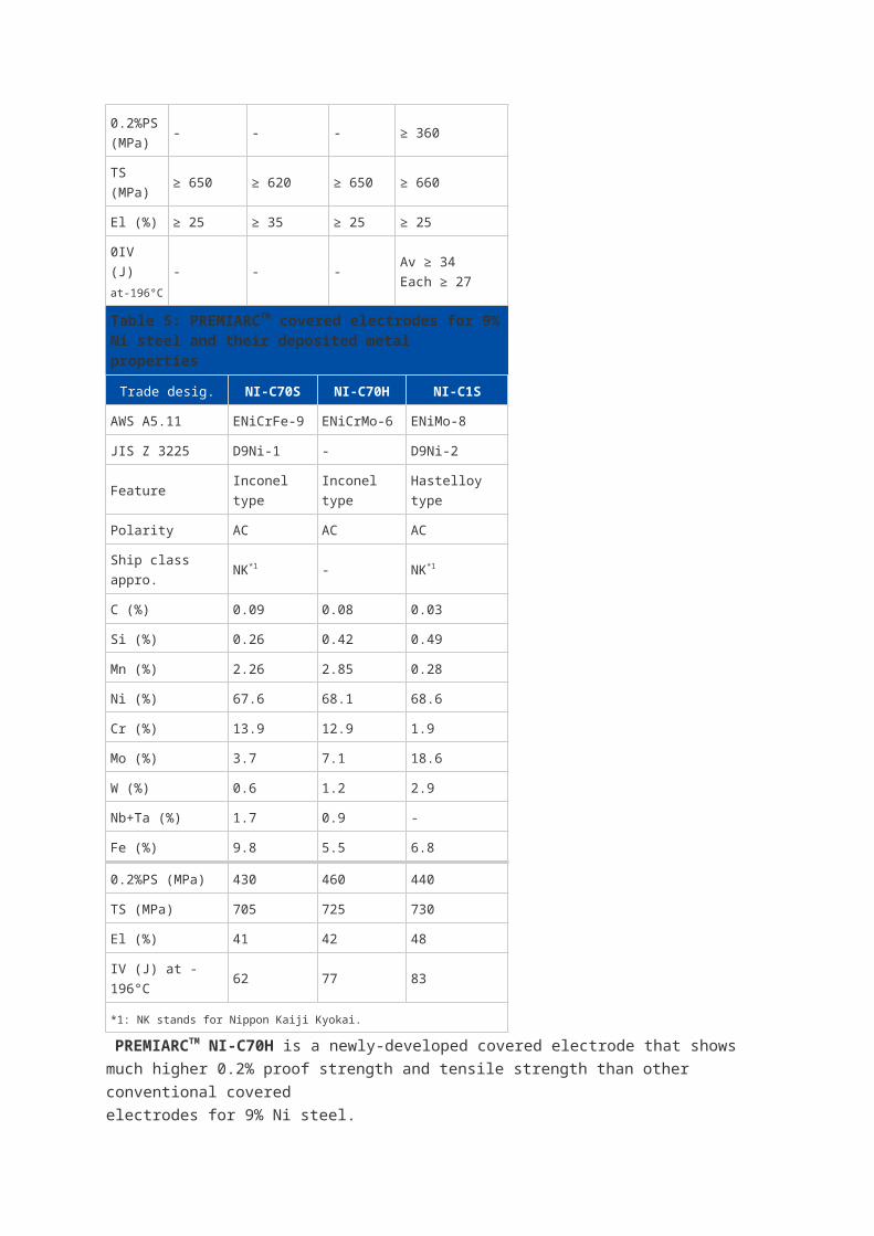
Table 5: PREMIARCTM covered electrodes for 9% Ni steel and their deposited metal properties
Trade desig. NI-C70S NI-C70H NI-C1S
AWS A5.11 ENiCrFe-9 ENiCrMo-6 ENiMo-8
JIS Z 3225 D9Ni-1 - D9Ni-2
Feature Inconel type Inconel type Hastelloy type
Polarity AC AC AC
Ship class appro. NK*1 - NK*1
C (%) 0.09 0.08 0.03
Si (%) 0.26 0.42 0.49
Mn (%) 2.26 2.85 0.28
Ni (%) 67.6 68.1 68.6
Cr (%) 13.9 12.9 1.9
Mo (%) 3.7 7.1 18.6
W (%) 0.6 1.2 2.9
Nb+Ta (%) 1.7 0.9 -
Fe (%) 9.8 5.5 6.8
0.2%PS (MPa) 430 460 440
TS (MPa) 705 725 730
El (%) 41 42 48
IV (J) at -196°C 62 77 83
*1: NK stands for Nippon Kaiji Kyokai.
PREMIARCTM NI-C70H is a newly-developed covered electrode that shows much higher 0.2%
proof strength and tensile strength than other conventional covered
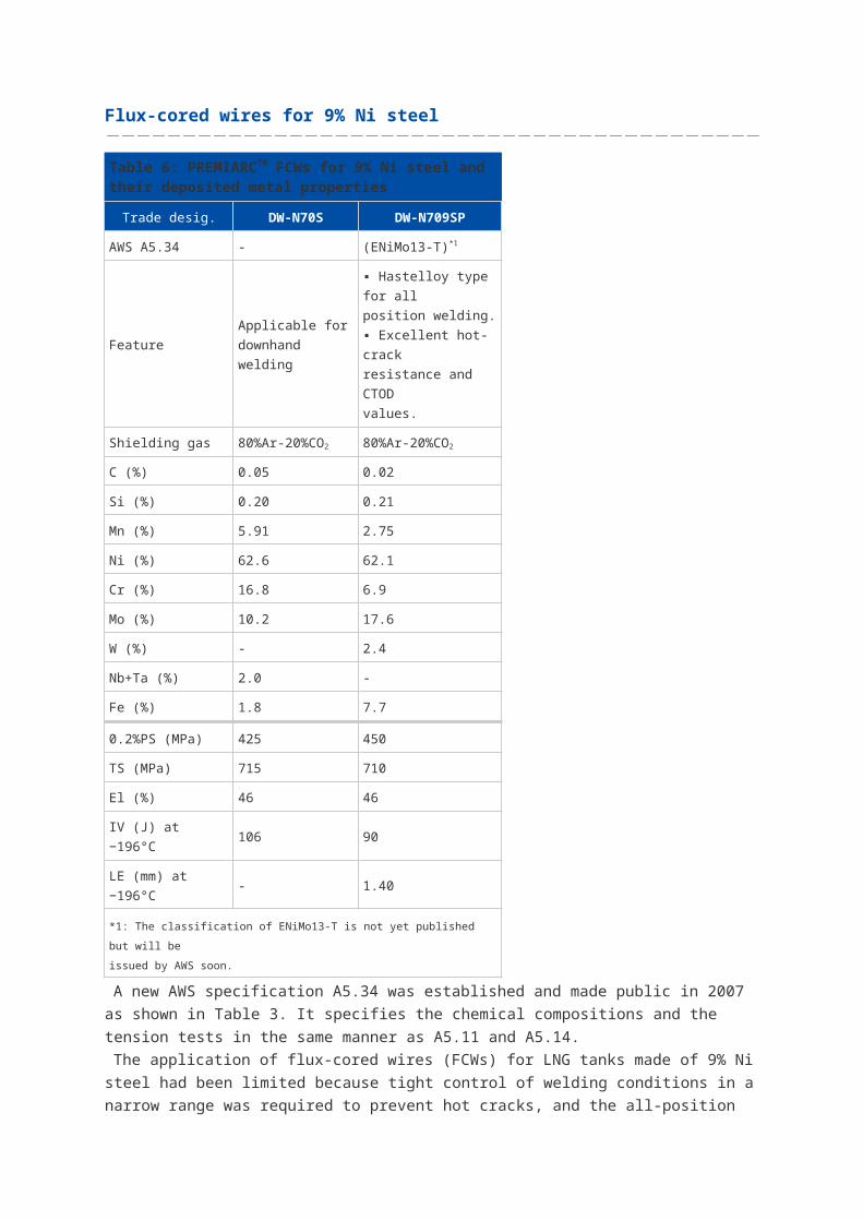
electrodes for 9% Ni steel.Flux-cored wires for 9% Ni steel
Table 6: PREMIARCTM FCWs for 9% Ni steel and their deposited metal properties
Trade desig. DW-N70S DW-N709SP
AWS A5.34 - (ENiMo13-T)*1
FeatureApplicable for
downhand welding
▪ Hastelloy type for all
position welding.
▪ Excellent hot-crack
resistance and CTOD
values.
Shielding gas 80%Ar-20%CO2 80%Ar-20%CO2
C (%) 0.05 0.02
Si (%) 0.20 0.21
Mn (%) 5.91 2.75
Ni (%) 62.6 62.1
Cr (%) 16.8 6.9
Mo (%) 10.2 17.6
W (%) - 2.4
Nb+Ta (%) 2.0 -
Fe (%) 1.8 7.7
0.2%PS (MPa) 425 450
TS (MPa) 715 710
El (%) 46 46
IV (J) at −196°C 106 90
LE (mm) at −196°C - 1.40
*1: The classification of ENiMo13-T is not yet published but will be
issued by AWS soon.
A new AWS specification A5.34 was established and made public in 2007 as shown in Table 3.
It specifies the chemical compositions and the tension tests in the same manner as A5.11 and
A5.14.
The application of flux-cored wires (FCWs) for LNG tanks made of 9% Ni steel had been limited
because tight control of welding conditions in a narrow range was required to prevent hot cracks,
and the all-position welding was difficult. However, as shown in Table 6, Kobe Steel has
developed two types of the FCWs for welding 9% Ni steel that solve these problems, and
recently they have been put into operation. PREMIARCTM DW-N70S is designed for down-hand
welding and a new FCW, PREMIARCTM DWN709SP, for all position welding as shown in Table
6.
DW-N709SP is introduced here as A5.34 (ENiMo13-T), because there is not such a
classification in A5.34 yet. According to the latest information, the revised A5.34, which will cover
ENiMo13-T, will be issued by AWS soon. For more detailed technical information related to DW-
N709SP, please see “Kobelco Welding Today, Vol. 13 No. 1 2010.”
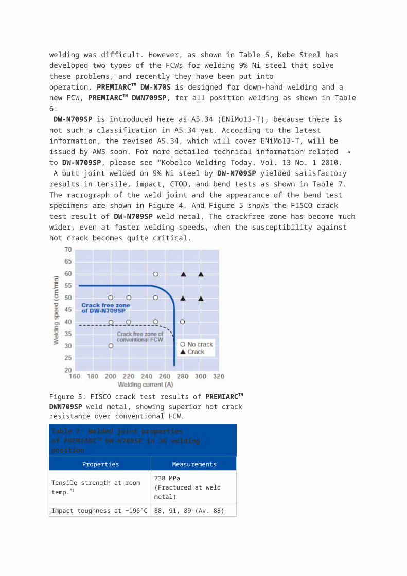
A butt joint welded on 9% Ni steel by DW-N709SP yielded satisfactory results in tensile, impact,
CTOD, and bend tests as shown in Table 7. The macrograph of the weld joint and the
appearance of the bend test specimens are shown in Figure 4. And Figure 5 shows the FISCO
crack test result of DW-N709SP weld metal. The crackfree zone has become much wider, even
at faster welding speeds, when the susceptibility against hot crack becomes quite critical.
Figure 5: FISCO crack test results of PREMIARCTM DWN709SP weld metal, showing superior hot crack resistance over conventional FCW.
Table 7: Welded joint properties of PREMIARCTM DW-N709SP in 3G welding position
Properties Measurements
Tensile strength at room temp.*1 738 MPa
(Fractured at weld metal)
Impact toughness at −196°C 88, 91, 89 (Av. 88) (J)
CTOD at −196°C (δM) 0.39, 0.39, 0.38 (Av. 0.38)
Longitudinal bending, 180° Good
*1: Base metal is ASTM A553 Type I, 28mm thick, double-V groove.
Figure 4: PREMIARCTM DW-N709SP exhibits completefusion in 3G-position butt joint and excellent ductility in bendtest.
TIG welding wire for 9% Ni steel
Table 8: AWS and JIS specifications for TIG wires for 9% Ni steel and the properties of the matching filler wire PREMIARCTM TG-S709S
Properties *1
Classifications Trade designation
AWS A5.14
ERNiMo-8
JIS Z 3332
YGT9Ni-2TG-S709S
Features - -
▪ Hastelloy type wire
and rod.
▪ Suitable for
automatic GTAW
Ship class appro. - - NK
C (%) ≤ 0.10 ≤ 0.10 0.02
Si (%) ≤ 0.75 ≤ 0.75 0.03
Mn (%) ≤ 1.5 ≤ 3.0 0.03
Ni (%) ≥ 60.0 ≥ 60.0 70.4
Cr (%) 0.5-3.5 - 2.0
Mo (%) 17.0-20.0 15.0-22.0 19.0
W (%) 2.0-4.0 1.5-5.0 3.0
Fe (%) ≤ 10.0 ≤ 12.0 5.5
0.2%PS (MPa) - ≥ 360 460
TS (MPa) - ≥ 660 730
El (%) - ≥ 25 47
IV (J) at −196°C -Av ≥ 34,
Each ≥ 27160
*1: Chemical compositions are for wire. Mechanical properties are for
deposited metal.
Ever since Kobe Steel’s MC-TIL process for automatic TIG welding was developed in 1973, it
has been applied widely by tank fabricators, particularly in Japan. Overseas, it has been adopted
in more than 10 units of LNG tanks made of 9% Ni steel and in about 60 units in the Japanese
domestic market.
This efficient automatic TIG welding involves the application of a large welding current and the
intentional deflection of arc direction by magnetic force, and it is able to maintain the soundness
of weld metal, the principle advantage of GTAW. It is two times more efficient than SMAW and
four times more than manual GTAW. Furthermore, the process reduced the defect ratio to almost
zero and improved the completion time, total cost and quality of the weld.
AWS and JIS specifications for TIG wires for 9% Ni steel and the properties of the matching
filler wire PREMIARCTM TG-S709S are shown in Table 8.
SAW wires and fluxes for 9% Ni steel
Table 9: AWS specifications for SAW wire and JIS specifications for SAW wire and flux combinations for 9% Ni steel
Classification
AWS A5.14 JIS Z 3333
ERNiMo-8 FS9Ni-F/YS9Ni FS9Ni-H/YS9Ni
Applicable to wire Weld metal Weld metal
C (%) ≤ 0.10 ≤ 0.10 ≤ 0.10
Si (%) ≤ 0.75 ≤ 1.5 ≤ 1.5
Mn (%) ≤ 1.5 ≤ 3.5 ≤ 3.5
Ni (%) ≥ 60.0 ≥ 60.0 ≥ 60.0
Cr (%) 0.5-3.5 - -
Mo (%) 17.0-20.0 10.0-25.0 10.0-25.0
W (%) 2.0-4.0 - -
Fe (%) ≤ 10.0 ≤ 20.0 ≤ 20.0
0.2%PS (MPa) - ≥ 365 ≥ 365
TS (Mpa) - ≥ 660 ≥ 660
El (%) - ≥ 25 ≥ 25
IV (J) at −196°C -Av. ≥ 34
Each ≥ 27
Av. ≥ 34
Each ≥ 27
In its SAW specifications, the AWS regulates wires only in A5.14 whereas JIS specifies the
combination of wire and flux, as shown in Table 3 and Table 9. Kobe Steel’s SAW wire and flux
combinations are shown in Table 10.
Table 10: PREMIARCTM SAW wire and flux combinations for 9% Ni steel and their deposited metal properties
Trade Classification Features Pol. Ship Chemical composition (%) Mechanical properties
desig.
(Flux/wire)
class
appro.
AWS
A5.14
JIS
Z 3333C Si Mn Ni Cr Mo W Fe
0.2%PS
(MPa)
TS
(MPa)
El
(%)
IV (J) at
−196°C
PF-N3/
US-709S
ER
NiMo-8
(wire)
FS9Ni-
F/YS9Nil
▪ Hastelloy type
consumables
▪ Suitable for 1G
welding position
AC,
DCEP- 0.03 0.12 1.70 64.1 1.6 16.6 2.5 14.7 400 690 44 80
PF-N4/
US-709S
ER
NiMo-8
(wire)
FS9Ni-
F/YS9Nil
▪ Hastelloy type
consumables
▪ Suitable for 2G
welding position
DCEP NK 0.03 0.74 0.58 64.0 1.7 17.2 2.7 14.9 410 680 43 70
Welding procedures and control
The key factor for the economical and qualitative tank construction is to minimize the amount of
on-site fabrication work. This can be achieved by adopting modular design, in which each
module is fabricated at a plant and delivered to the site for the connection work afterwards. Even
the dome ceiling of an LNG tank is fabricated at a plant and connected to the shell onsite by
using the airraising process.
The welding joints that are typically carried out on 9% Ni steel components on-site is shown in
Figure 6. Table 11 shows the welding procedures used on individual joints.
Figure 6: Cross sectional view of typical welding joints in theshell and bottom of a 9% Ni steel tank in on-site fabrication.(Refer to Table 11 for individual welding procedures)
Table 11: Welding p rocedures f or i ndividual j oints ( Refer t o Figure 6 for each joint No.)
Joint No. ① ② ③ ④
Component Side shell Side shellBottom to
side shellBottom
Type of joint Double V Double V Double bevel Lap
Welding
position*1 3G 2G 2G 2F
Welding
process*2
SMAW
FCAW
Auto-TIG
SAW
Auto-TIG
SAW
Auto-TIG
SMAW
FCAW
Auto-TIG
*1: 3G (Vertical groove); 2G (Horizontal groove); 2F (Horizontal fillet).
*2: Kobelco auto-TIG welding equipment is available only in Japan.
[Note: Inconel is a trademark of Special Metals Corp.
Hastelloy is a trademark of Haynes International.]
Figure 7 shows examples of groove configurations for SMAW, GTAW, SAW and FCAW in
designated welding positions in the figure. Figure 8 shows horizontal fillet welding (2F) on the
roof of an LNG tank with DW-N709SP flux cored wire. Figure 9 shows overhead butt joint
welding (4G) along the bottom plate of an LNG tank with automatic TIG welding equipment using
TG-S709S TIG wire. These pictures were taken at a construction site in Japan where the major
aboveground LNG tanks use the flat-bottom double-shell cylindrical dome-roof structure (Figure
10). The dome roof is also made of 9% Ni steel.
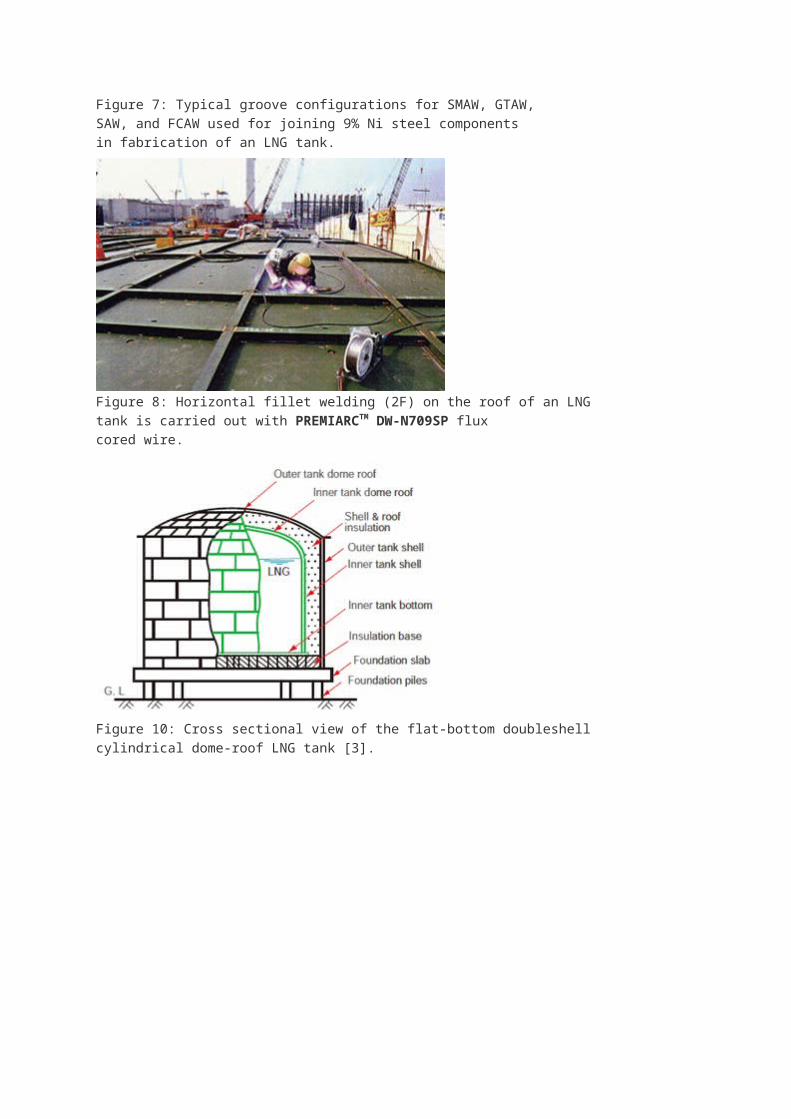
Figure 7: Typical groove configurations for SMAW, GTAW,SAW, and FCAW used for joining 9% Ni steel componentsin fabrication of an LNG tank.
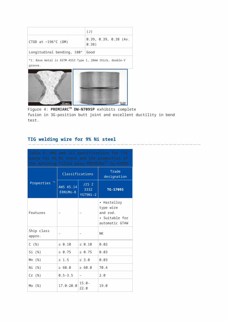
Figure 8: Horizontal fillet welding (2F) on the roof of an LNGtank is carried out with PREMIARCTM DW-N709SP fluxcored wire.
Figure 10: Cross sectional view of the flat-bottom doubleshellcylindrical dome-roof LNG tank [3].
Figure 9: Overhead butt joint welding (4G) along the bottomplate of an LNG tank is conducted with automatic TIGwelding equipment using PREMIARCTM TG-S709S TIG wire.

Tips for better welding results on 9% Ni steel
High Ni alloy welding consumables are hot crack sensitive in general, and LNG tanks typically
require much dissimilar welding. The following special precautions against hot crack and base
metal dilution have to be taken.
Crater crack must be removed: Kobe Steel’s welding consumables for 9% Ni steel have been
proven to be adequate through the inspection by FISCO crack testing for hot crack susceptibility.
However, because crater cracks (one type of hot crack) are common and difficult to avoid, it is
strongly recommended for the crater to be ground off each time when the arc stops.
Dilution of base metal affects the mechanical properties of the weld metal: When the base
metal is diluted into the weld metal by the arc, the weld metal chemistries can change. These
changes can be especially more significant in dissimilar welding, decreasing the tensile strength
of the weld metal. It is advised to check the welding conditions and to ensure that the tensile
strength and 0.2% proof strength fulfill the requirements in the procedure test in advance.
The ABC’s of Arc Welding
How to calculate welding consumption
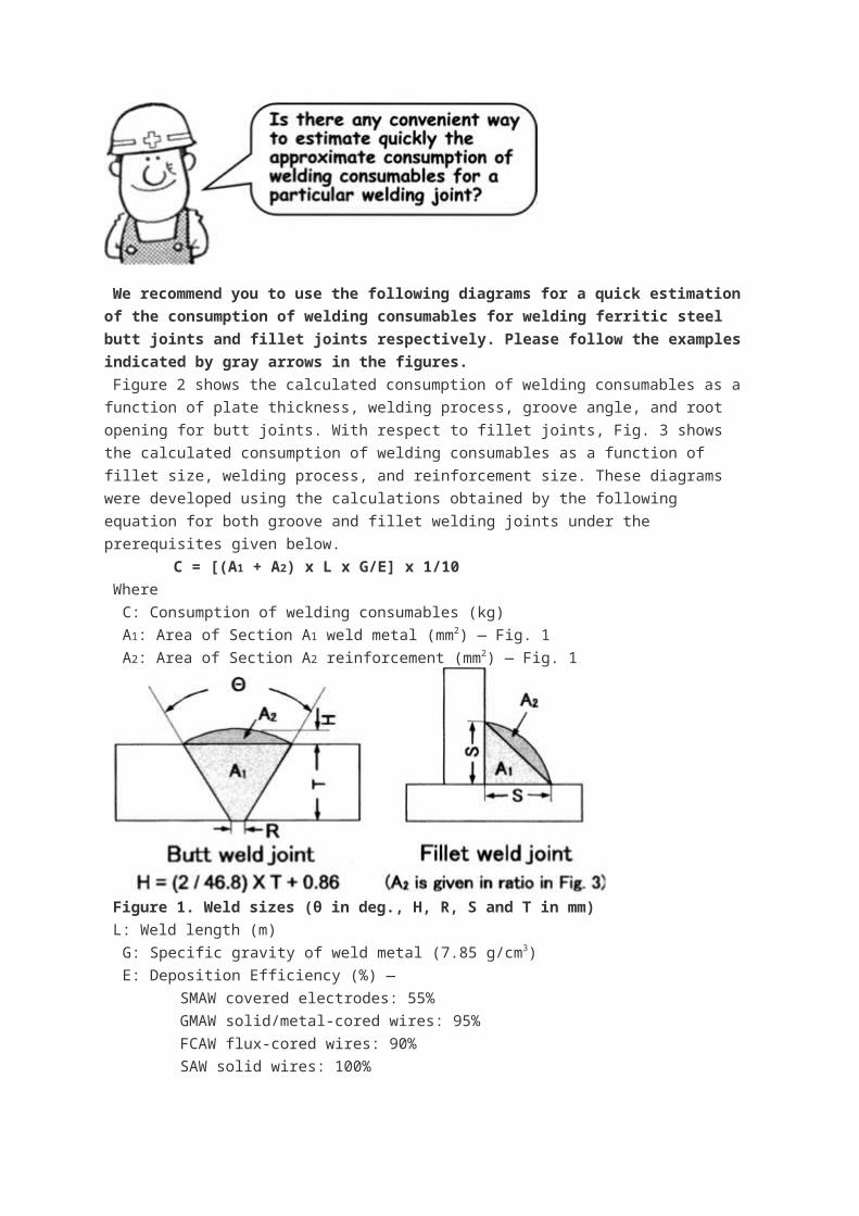
We recommend you to use the following diagrams for a quick estimation of the
consumption of welding consumables for welding ferritic steel butt joints and fillet joints
respectively. Please follow the examples indicated by gray arrows in the figures.
Figure 2 shows the calculated consumption of welding consumables as a function of plate
thickness, welding process, groove angle, and root opening for butt joints. With respect to fillet
joints, Fig. 3 shows the calculated consumption of welding consumables as a function of fillet
size, welding process, and reinforcement size. These diagrams were developed using the
calculations obtained by the following equation for both groove and fillet welding joints under the
prerequisites given below.
C = [(A1 + A2) x L x G/E] x 1/10
Where
C: Consumption of welding consumables (kg)
A1: Area of Section A1 weld metal (mm2) ― Fig. 1
A2: Area of Section A2 reinforcement (mm2) ― Fig. 1
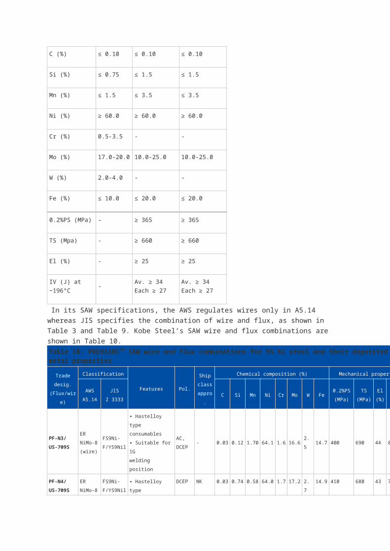
Figure 1. Weld sizes (θ in deg., H, R, S and T in mm)
L: Weld length (m)
G: Specific gravity of weld metal (7.85 g/cm3)
E: Deposition Efficiency (%) ―
SMAW covered electrodes: 55%
GMAW solid/metal-cored wires: 95%
FCAW flux-cored wires: 90%
SAW solid wires: 100%
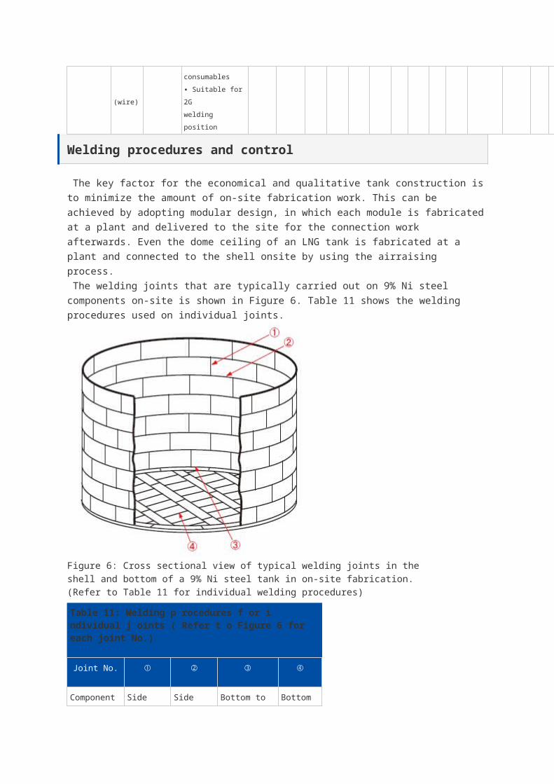
Figure 2. Consumption of covered electrodes in SMAW and solid/metal-cored wires in
GMAW of butt joints.
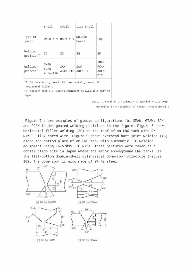
Figure 3. Consumption of covered electrodes in SMAW, fluxcored wires in FCAW,
solid/metal-cored wires in GMAW, and solid wires in SAW of fillet jointsThe ABC’s of Arc Welding
Q and A: Rust on a stainless steel weld
Question:
We delivered 304-type stainless steel joints welded with the flux-cored wire, DW-308. Two
weeks later, our customer complained that rust was forming on the surface of some of the weld
beads. What causes this problem? In addition, we found that the remaining wire of the DW-308
would stick to a magnet. We thought that DW-308 would not stick to a magnet. What has
happened with the wire?
Answer:
It is often said that stainless steels do not rust. This is not true; however, they are less likely to
generate rust compared to conventional carbon and special steels. It is helpful to understand the
way that each type of steel forms rust.
The case you described of rust forming on the beads was likely a type of rust that forms on
dissimilar metals like a combination of carbon steel and stainless steel. This type of rust can be
caused by such external factors as carbon steel powders enerated by nearby grinding and
brushing with carbon steel wire brushes, adhering to the surface of the stainless steel weld
beads. Therefore, we guess that some carbon steel powders that had adhered to the surface of
the DW-308 weld beads caused the rust in your case.
Figures 1 and 2 show examples of bead appearance. The rusty bead in Figure 1 had been
brushed with a carbon steel wire brush, while the other metallic, lustrous one in Figure 2 had
been brushed with a stainless steel wire brush. The former one clearly has brown rust even on
the base metal. You can therefore understand that stainless steel wire brushes are essential for
brushing stainless steel welded joints.
You might have thought that the magnet and the wire were attracted to each other due to some
ingredients contained in the DW-308 wire. The DW-308 wire indeed does react magnetically
because of the stress-induced martensite on the surface of the wire. The martensite structure is
formed by work hardening the surface of the wire during the process of drawing into the
designated diameter. The stress-induced martensite, however, has nothing to do with rusting.
The DW-308 weld metal also behaves magnetically. This phenomenon is caused by a small
amount of ferrite contained in the weld metal. With the desire to keep the cracking susceptibility
of the weld metal as low as possible, DW-308 is designed to contain small amounts of ferrite in
the weld metal. The ferrite tructure also has nothing to do with rust.
If the rust problem described above is not so serious, it can be wiped off with a sponge or cloth
soaked with neutral detergent or soapy water. Careful washing with water is necessary afterward
so as not to leave any neutral detergent or soapy water. When it is serious, use an exclusive
cleaning solution for stainless steel or 15% diluted nitric acid. Polishing with sand paper or
brushing off with a stainless steel wire brush is also effective. When followed by cleaning with
soapy water, it will be perfect for obtaining beautiful welds.
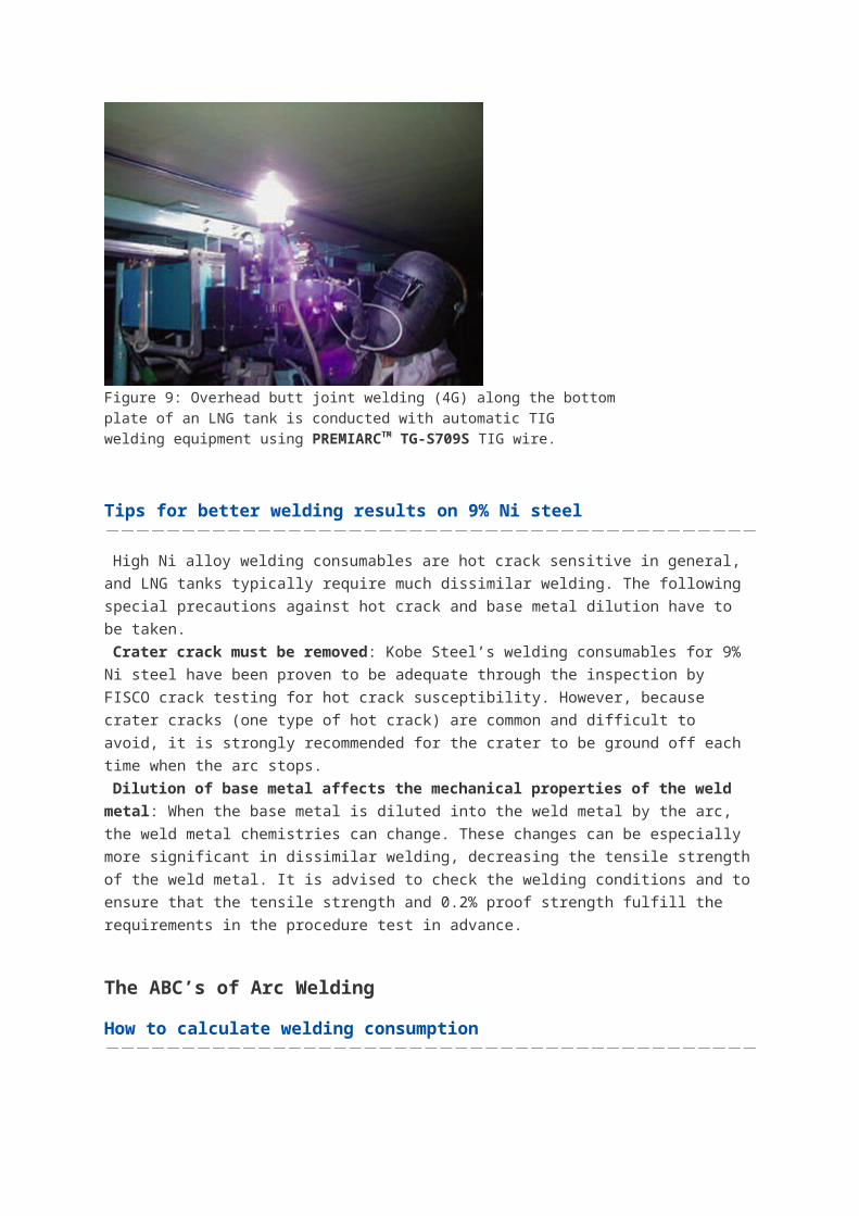
Figure 1: Rusty appearance of a weld bead after brushing with a carbon steel wire brush
Figure 2: Metallic, lustrous appearance of a weld bead brushed with a stainless steel
wire brush
Welding of Galvanized Steel Sheets
Question:
We weld a variety of galvanized steel sheets by semi-automatic CO2 welding. However we
have a hard time with postweld treatment and repair, because pits occur often and a lot of spatter
is generated. Could you please explain how porosity and spatter generate with galvanized steel
sheets and recommend a good welding wire to solve these problems?
Answer:
Galvanized steel sheets are widely used in many steel structures like cars, steel towers, bridges
and buildings because of their cost-effectiveness due to excellent corrosion resistance and rust
prevention. They include hot-dip galvanized steels, 5%Alalloyed hot-dip galvanized steels,
55%Al-alloyed hot-dip galvanized steels, electrogalvanized steels, and other galvanized steels.
The weldability of these steels is related to the amount of zinc coating (g/m2). The thicker the
zinc coating, the more the porosity (pits and blowholes) and spatter that result in arc welding.
Porosity can be understood by noting that the zinc coating decomposes in the arc heat and that
the zinc vaporizes at around 900°C to become a gas, causing bubbles in the weld pool and
porosity in the weld metal. As to the increase of spatter, The force of the zinc vapor jet against
the arc likely causes the metal droplet transfer to become unstable, thereby expelling the metal
droplets outside the arc as spatter.
A variety of porosity-resistant low-spatter welding wires for galvanized steel sheets have been
developed. These wires have sophisticated chemical compositions that suppress the growth of
gas bubbles trapped in the weld pool and stabilize metal droplet transfer.
Cars, electric machinery, office equipment, and vending machines typically adopt electro-
galvanized steel sheets with 50g/m2 or less of coating and alloyed hot-dip galvanized steel
sheets with 40-100g/m2 of coating. For these thin-coated steel sheets, solid wires, such as MG-
1Z (for CO2 gas shielding), MIX-1Z (for Ar-CO2 mixed gas shielding), and MIX-1TS (for Ar-
CO2 mixed gas shielding and pulsed current) are recommended.
Table 1 shows the applications for and characteristics of the above-mentioned welding wires. If
you take into account the shielding gas composition and the power source output characteristics
when selecting a wire, you will be able to perform highly efficient welding resulting in high quality
welds, less porosity, and low spatter.
Table 1: Solid wires for gas metal arc welding of galvanized steel sheets
Name of
Wire
Diameter
(mm)
AWS
StandardApplication Characteristics
MG-1Z 1.0, 1.2A5.18
ER70S-GParts for cars,
rolling stock,
housings,
electric
machinery
For CO2 gas shielding.
Suitable for sheets with a zinc coating of up to
about 60g/m2.
MIX-1Z 1.0, 1.2A5.18
ER70S-G
For Ar+CO2 mixed gas shielding.
Pulsed current brings about less porosity.
MIX-1TS 1.2A5.18
ER70S-G
For Ar+CO2 mixed gas shielding with pulsed
current.
Extremely less porosity and spatter.
Recommended