http://www.iaeme.com/IJCIET/index.asp 833 [email protected]
International Journal of Civil Engineering and Technology (IJCIET) Volume 8, Issue 8, August 2017, pp. 833–840, Article ID: IJCIET_08_08_086
Available online at http://http://www.iaeme.com/ijciet/issues.asp?JType=IJCIET&VType=8&IType=8
ISSN Print: 0976-6308 and ISSN Online: 0976-6316
© IAEME Publication Scopus Indexed
TANGENTIAL STRESS FACTOR
COMPUTATION IN POINT MOUNTED
STRUCTURAL GLASS
B. Venkatesh
Department of Aerospace Engineering, RVCE, Bangalore, India
Gowtham Reddy G
Department of Aerospace Engineering, RVCE, Bangalore, India
Benjamin Rohit
Department of Aerospace Engineering, RVCE, Bangalore, India
Syed Sharin,
Department of Mechanical Engineering, PESIT-BSC, Bangalore, India
ABSTRACT
The main objective in this study is to compute the stress factors when the effect of
countersinking a hole comes into play in comparison with the stress factors computed
for a cylindrical straight bolt hole in accordance with DIN 18008-3. FEM analysis
using 3-D volume elements were done with the commercially available software
Abaqus. The study was carried out for various dimensional parameters of point
mounted glass. This study has also carried out parametric sensitivity analysis for a
single counter-sunk bolt hole and a double counter-sunk bolt to compute the increase
in the tangential stress factor values when changing over from a straight cylindrical
hole to a countersunk and a double countersunk hole. It was found that the stress
factors increase when the hole is countersunk.
Key words: DIN 18008-3, Counter-Sunk Bolting, Double Counter-Sunk
Cite this Article: B. Venkatesh, Gowtham Reddy G, Benjamin Rohit and Syed
Sharin, Tangential Stress Factor Computation in Point Mounted Structural Glass,
International Journal of Civil Engineering and Technology, 8(8), 2017, pp. 833–840.
http://www.iaeme.com/IJCIET/issues.asp?JType=IJCIET&VType=8&IType=8
1. INTRODUCTION
Glass is a highly brittle material but also an eco-friendly material used for construction of
buildings to allow sunlight for lighting the interiors. But since it is highly brittle safety is
always a point of concern. It is very difficult to analyze crack growth and crack propagation.
B. Venkatesh, Gowtham Reddy G, Benjamin Rohit and Syed Sharin
http://www.iaeme.com/IJCIET/index.asp 834 [email protected]
Hence it is very much necessary to know the limits to which the stresses can be produced in
the glass material. There is a lack of knowledge when it comes to simple design tools during
the use of structural glass. This study deals with the development of efficient and linear tool
for the design of glass bolting in point supported glass in accordance with DIN18008-3
standard norms. The support conditions have been advanced for different type of boltings. As
there is less work done in this field, there is very less literature available for point mounted
glass in accordance with DIN 18008-3.
2. DIN 18008-3 – COMPUTATION OF STRESS FACTORS.
Technical Experiment for Point mounted Glazing. For standard DIN 18008:2010-12 the
design value (limit stress) depends on the type of the glass. The maximum limit stress for
thermally toughened glass is given by
������,� = ������, .�
�� (�)
Where,
� : Construction Factor
������,� : Characteristic limit stress value
�� : Partial Factor
Maximum limit stress for a glass which is not thermally toughened,
������,� = ������, .�
�� . ��� (�)
Where, ��� is the correction factor.
Now we will be discussing the stress factors due to the loading and at the bore of a point
supported glazing. The stresses are calculated using the simplified method of the linear
superposition of local and global stress components as shown in equation.
���� =����
��.����
��
. ���. ��� (�)
Where,
���� : Stress factor for Force ��
���� : Reference thickness as per DIN 18008-3
�� : Thickness of the glass
��� : Shear Force
!� = ��",� + ���,� + ��,� + . �$,� (%)
Where,
!� : Design value of Loading
��",� : Local Stress component resulting from the normal force in Z direction
���,� : Local Stress component resulting from the shear force in XY direction
��,� : Local Stress component resulting from the Bearing Torque
. �$,� : Stress Factor k and Global stress component
At the present this is only available for cylindrical hole bolting. We would like to expand
this methodology to countersunk bolting and check for the increase in safety factors between
cylindrical and countersunk holes.
Tangential Stress Factor Computation in Point Mounted Structural Glass
http://www.iaeme.com/IJCIET/index.asp 835 [email protected]
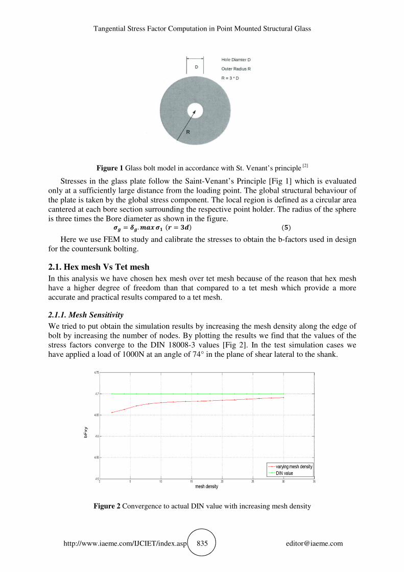
Figure 1 Glass bolt model in accordance with St. Venant’s principle [2]
Stresses in the glass plate follow the Saint-Venant’s Principle [Fig 1] which is evaluated
only at a sufficiently large distance from the loading point. The global structural behaviour of
the plate is taken by the global stress component. The local region is defined as a circular area
cantered at each bore section surrounding the respective point holder. The radius of the sphere
is three times the Bore diameter as shown in the figure. �$ = �$. �&� �� (� = ��) (')
Here we use FEM to study and calibrate the stresses to obtain the b-factors used in design
for the countersunk bolting.
2.1. Hex mesh Vs Tet mesh
In this analysis we have chosen hex mesh over tet mesh because of the reason that hex mesh
have a higher degree of freedom than that compared to a tet mesh which provide a more
accurate and practical results compared to a tet mesh.
2.1.1. Mesh Sensitivity
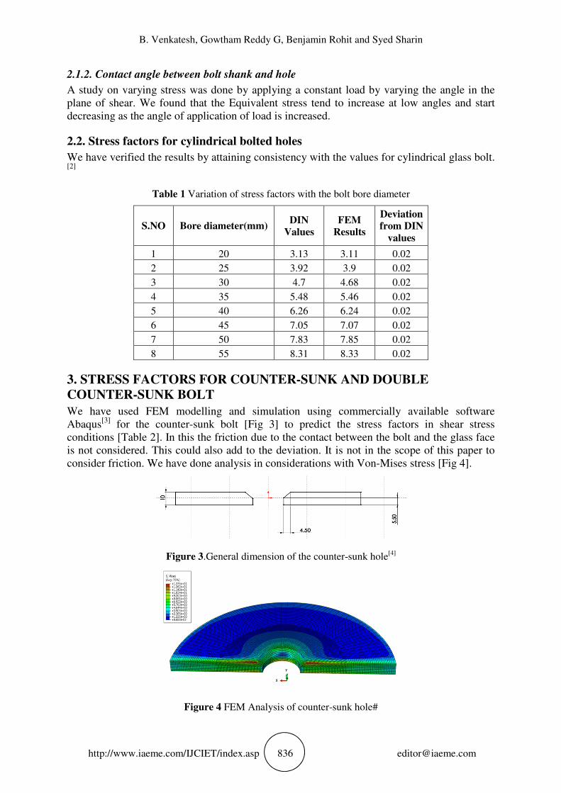
We tried to put obtain the simulation results by increasing the mesh density along the edge of
bolt by increasing the number of nodes. By plotting the results we find that the values of the
stress factors converge to the DIN 18008-3 values [Fig 2]. In the test simulation cases we
have applied a load of 1000N at an angle of 74° in the plane of shear lateral to the shank.
Figure 2 Convergence to actual DIN value with increasing mesh density
B. Venkatesh, Gowtham Reddy G, Benjamin Rohit and Syed Sharin
http://www.iaeme.com/IJCIET/index.asp 836 [email protected]
2.1.2. Contact angle between bolt shank and hole
A study on varying stress was done by applying a constant load by varying the angle in the
plane of shear. We found that the Equivalent stress tend to increase at low angles and start
decreasing as the angle of application of load is increased.
2.2. Stress factors for cylindrical bolted holes
We have verified the results by attaining consistency with the values for cylindrical glass bolt.
[2]
Table 1 Variation of stress factors with the bolt bore diameter
S.NO Bore diameter(mm) DIN
Values
FEM
Results
Deviation
from DIN
values
1 20 3.13 3.11 0.02
2 25 3.92 3.9 0.02
3 30 4.7 4.68 0.02
4 35 5.48 5.46 0.02
5 40 6.26 6.24 0.02
6 45 7.05 7.07 0.02
7 50 7.83 7.85 0.02
8 55 8.31 8.33 0.02
3. STRESS FACTORS FOR COUNTER-SUNK AND DOUBLE
COUNTER-SUNK BOLT
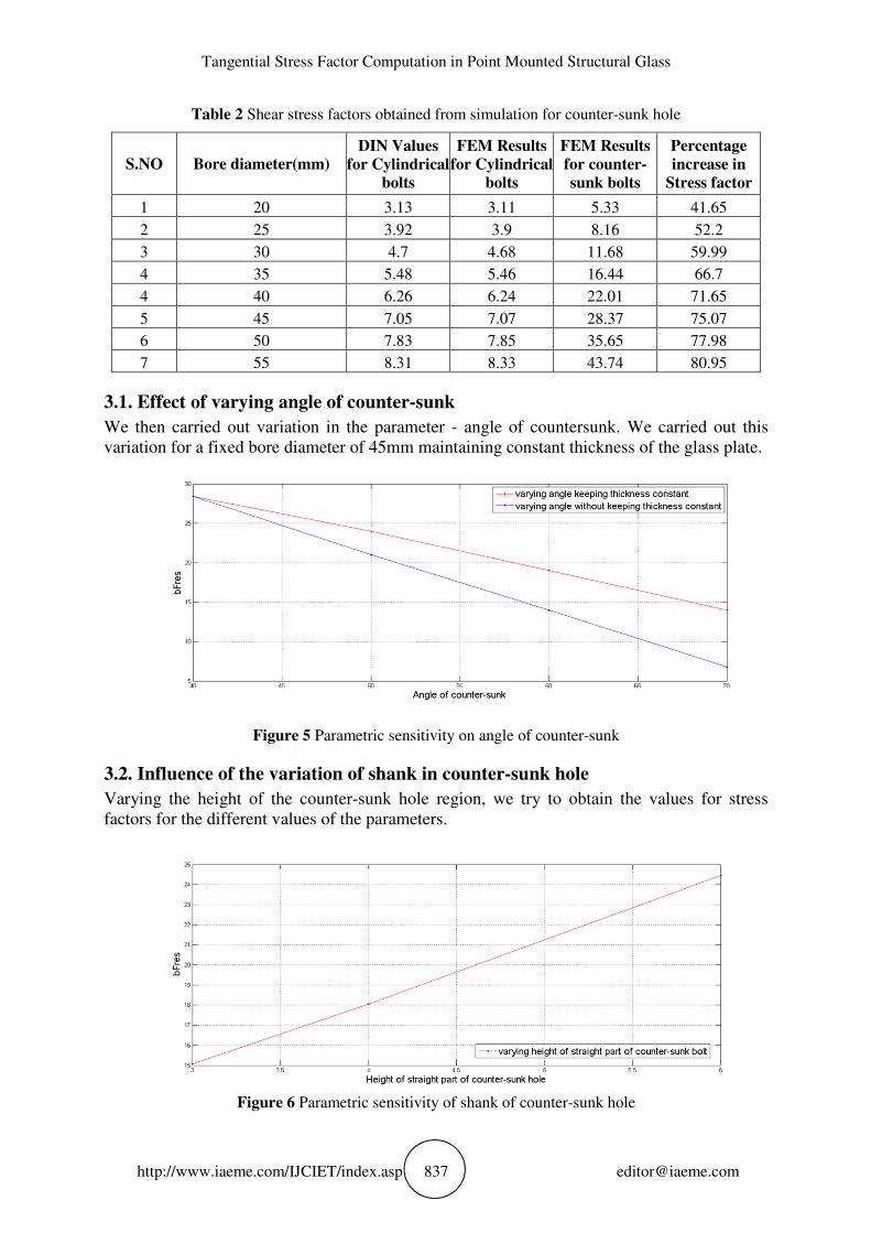
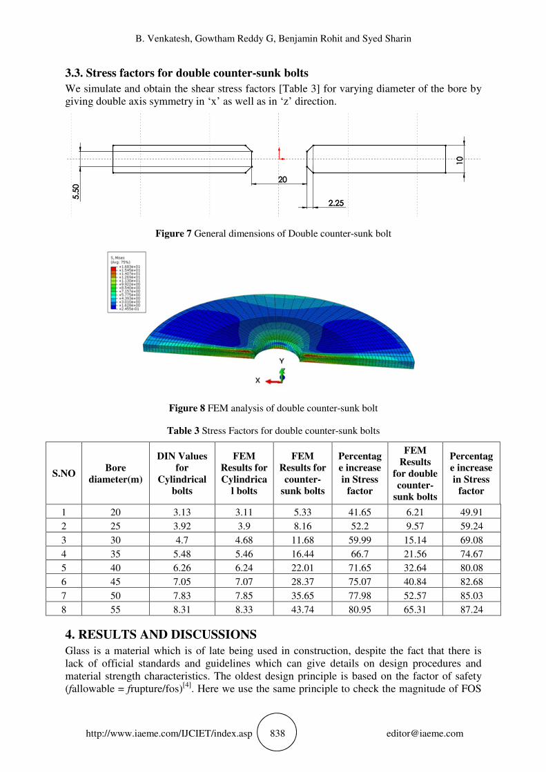
We have used FEM modelling and simulation using commercially available software
Abaqus[3]
for the counter-sunk bolt [Fig 3] to predict the stress factors in shear stress
conditions [Table 2]. In this the friction due to the contact between the bolt and the glass face
is not considered. This could also add to the deviation. It is not in the scope of this paper to
consider friction. We have done analysis in considerations with Von-Mises stress [Fig 4].
Figure 3.General dimension of the counter-sunk hole[4]
Figure 4 FEM Analysis of counter-sunk hole#
Tangential Stress Factor Computation in Point Mounted Structural Glass
http://www.iaeme.com/IJCIET/index.asp 837 [email protected]
Table 2 Shear stress factors obtained from simulation for counter-sunk hole
S.NO Bore diameter(mm)
DIN Values
for Cylindrical
bolts
FEM Results
for Cylindrical
bolts
FEM Results
for counter-
sunk bolts
Percentage
increase in
Stress factor
1 20 3.13 3.11 5.33 41.65
2 25 3.92 3.9 8.16 52.2
3 30 4.7 4.68 11.68 59.99
4 35 5.48 5.46 16.44 66.7
4 40 6.26 6.24 22.01 71.65
5 45 7.05 7.07 28.37 75.07
6 50 7.83 7.85 35.65 77.98
7 55 8.31 8.33 43.74 80.95
3.1. Effect of varying angle of counter-sunk
We then carried out variation in the parameter - angle of countersunk. We carried out this
variation for a fixed bore diameter of 45mm maintaining constant thickness of the glass plate.
Figure 5 Parametric sensitivity on angle of counter-sunk
3.2. Influence of the variation of shank in counter-sunk hole
Varying the height of the counter-sunk hole region, we try to obtain the values for stress
factors for the different values of the parameters.
Figure 6 Parametric sensitivity of shank of counter-sunk hole
B. Venkatesh, Gowtham Reddy G, Benjamin Rohit and Syed Sharin
http://www.iaeme.com/IJCIET/index.asp 838 [email protected]
3.3. Stress factors for double counter-sunk bolts
We simulate and obtain the shear stress factors [Table 3] for varying diameter of the bore by
giving double axis symmetry in ‘x’ as well as in ‘z’ direction.
Figure 7 General dimensions of Double counter-sunk bolt
Figure 8 FEM analysis of double counter-sunk bolt
Table 3 Stress Factors for double counter-sunk bolts
S.NO Bore
diameter(m)
DIN Values
for
Cylindrical
bolts
FEM
Results for
Cylindrica
l bolts
FEM
Results for
counter-
sunk bolts
Percentag
e increase
in Stress
factor
FEM
Results
for double
counter-
sunk bolts
Percentag
e increase
in Stress
factor
1 20 3.13 3.11 5.33 41.65 6.21 49.91
2 25 3.92 3.9 8.16 52.2 9.57 59.24
3 30 4.7 4.68 11.68 59.99 15.14 69.08
4 35 5.48 5.46 16.44 66.7 21.56 74.67
5 40 6.26 6.24 22.01 71.65 32.64 80.08
6 45 7.05 7.07 28.37 75.07 40.84 82.68
7 50 7.83 7.85 35.65 77.98 52.57 85.03
8 55 8.31 8.33 43.74 80.95 65.31 87.24
4. RESULTS AND DISCUSSIONS
Glass is a material which is of late being used in construction, despite the fact that there is
lack of official standards and guidelines which can give details on design procedures and
material strength characteristics. The oldest design principle is based on the factor of safety
(fallowable = frupture/fos)[4]
. Here we use the same principle to check the magnitude of FOS
Tangential Stress Factor Computation in Point Mounted Structural Glass
http://www.iaeme.com/IJCIET/index.asp 839 [email protected]
required while using a countersunk bolting. As there are no standard values for a countersunk
bolting in DIN 18008-3, we try to obtain stress factors for countersunk bolting to account for
the increase in the safety factor when changing from cylindrical bolting to counter-sunk
bolting and also when changing to double counter-sunk bolting we see the maximum stress
factors induced in it.
Equivalent stresses are found to be maximum in Double counter-sunk bolt. The maximum
stress is found to occur in two different regions as shown [Fig 8].This is mainly because of the
reason being that there is more surface in the inclined or angular region of the counter-sunk or
double counter-sunk bolt which induces higher stress in the shank.
We can note that as the bolt hole is being counter-sunk the degree of difference increases
quadratically and tends to be linear in case of a cylindrical bolt, this phenomenon has to be
studied in detail to be able to get a better understanding.
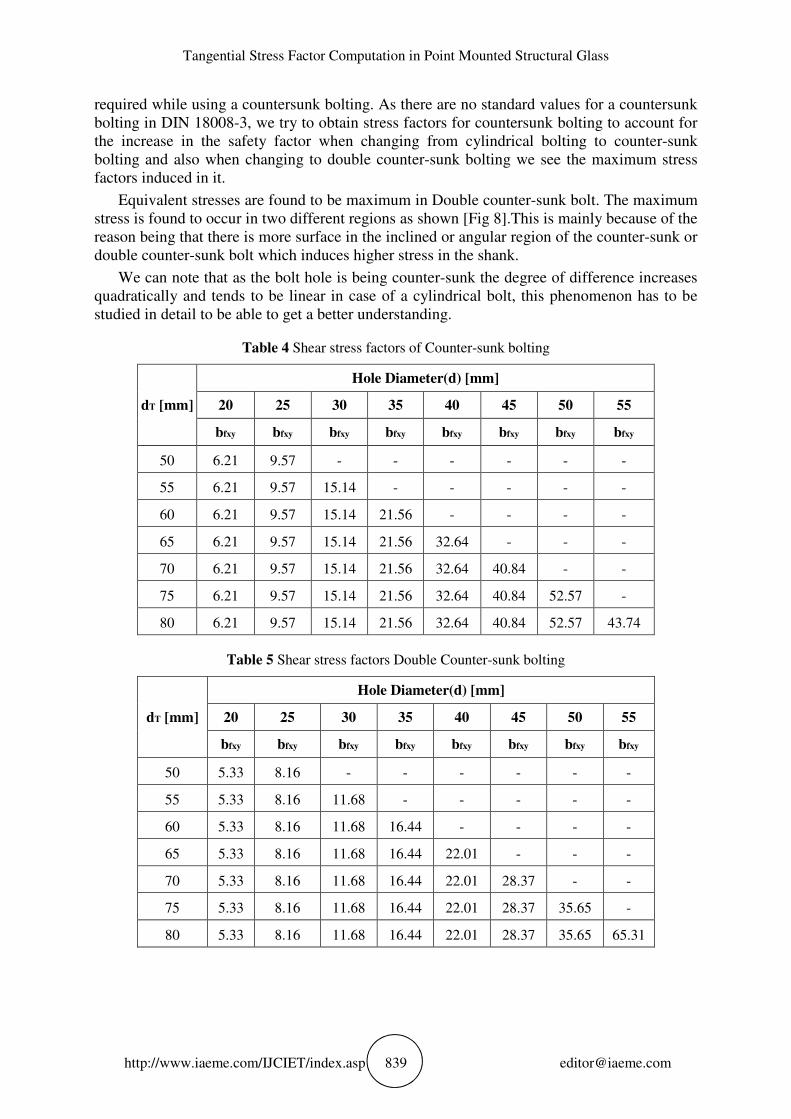
Table 4 Shear stress factors of Counter-sunk bolting
dT [mm]
Hole Diameter(d) [mm]
20 25 30 35 40 45 50 55
bfxy bfxy bfxy bfxy bfxy bfxy bfxy bfxy
50 6.21 9.57 - - - - - -
55 6.21 9.57 15.14 - - - - -
60 6.21 9.57 15.14 21.56 - - - -
65 6.21 9.57 15.14 21.56 32.64 - - -
70 6.21 9.57 15.14 21.56 32.64 40.84 - -
75 6.21 9.57 15.14 21.56 32.64 40.84 52.57 -
80 6.21 9.57 15.14 21.56 32.64 40.84 52.57 43.74
Table 5 Shear stress factors Double Counter-sunk bolting
dT [mm]
Hole Diameter(d) [mm]
20 25 30 35 40 45 50 55
bfxy bfxy bfxy bfxy bfxy bfxy bfxy bfxy
50 5.33 8.16 - - - - - -
55 5.33 8.16 11.68 - - - - -
60 5.33 8.16 11.68 16.44 - - - -
65 5.33 8.16 11.68 16.44 22.01 - - -
70 5.33 8.16 11.68 16.44 22.01 28.37 - -
75 5.33 8.16 11.68 16.44 22.01 28.37 35.65 -
80 5.33 8.16 11.68 16.44 22.01 28.37 35.65 65.31
B. Venkatesh, Gowtham Reddy G, Benjamin Rohit and Syed Sharin
http://www.iaeme.com/IJCIET/index.asp 840 [email protected]
5. CONCLUSION
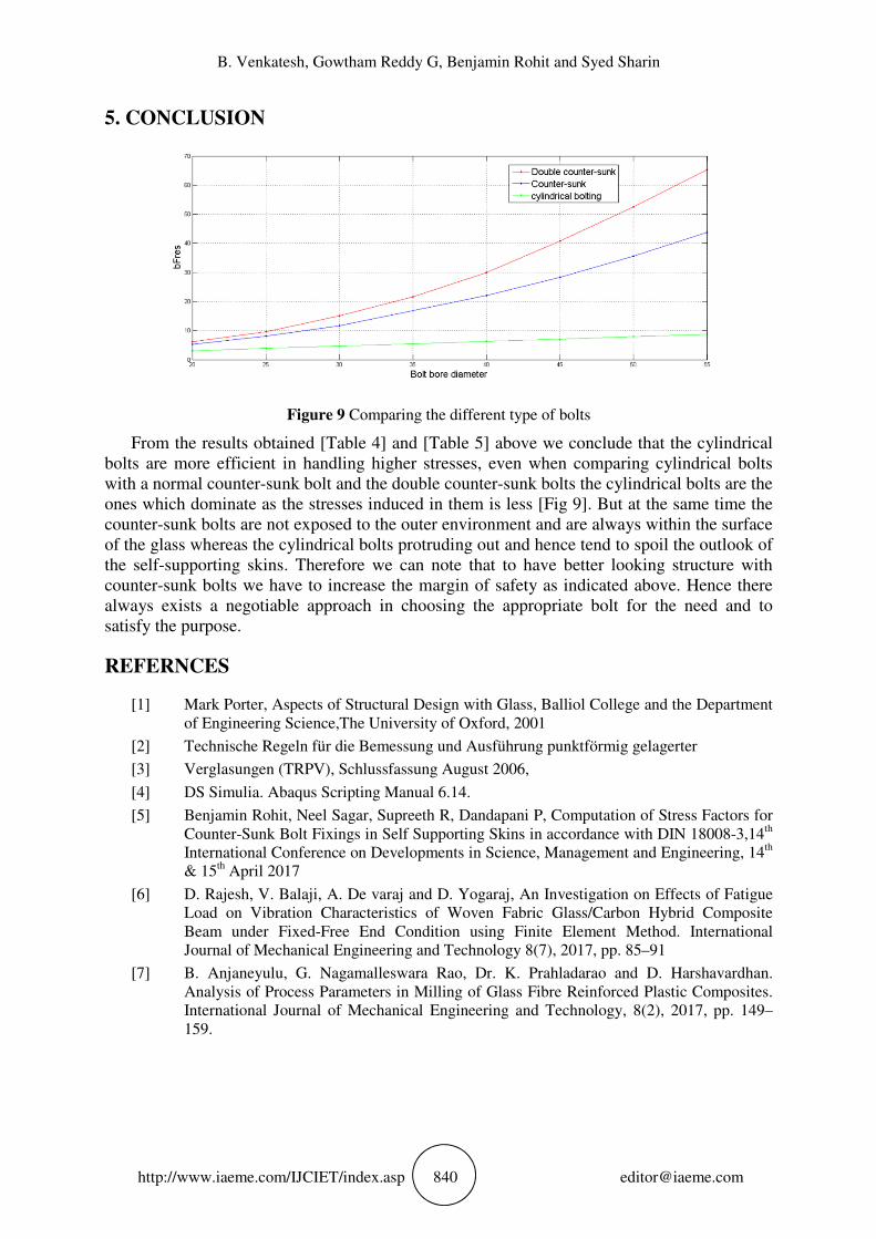
Figure 9 Comparing the different type of bolts
From the results obtained [Table 4] and [Table 5] above we conclude that the cylindrical
bolts are more efficient in handling higher stresses, even when comparing cylindrical bolts
with a normal counter-sunk bolt and the double counter-sunk bolts the cylindrical bolts are the
ones which dominate as the stresses induced in them is less [Fig 9]. But at the same time the
counter-sunk bolts are not exposed to the outer environment and are always within the surface
of the glass whereas the cylindrical bolts protruding out and hence tend to spoil the outlook of
the self-supporting skins. Therefore we can note that to have better looking structure with
counter-sunk bolts we have to increase the margin of safety as indicated above. Hence there
always exists a negotiable approach in choosing the appropriate bolt for the need and to
satisfy the purpose.
REFERNCES
[1] Mark Porter, Aspects of Structural Design with Glass, Balliol College and the Department
of Engineering Science,The University of Oxford, 2001
[2] Technische Regeln für die Bemessung und Ausführung punktförmig gelagerter
[3] Verglasungen (TRPV), Schlussfassung August 2006,
[4] DS Simulia. Abaqus Scripting Manual 6.14.
[5] Benjamin Rohit, Neel Sagar, Supreeth R, Dandapani P, Computation of Stress Factors for
Counter-Sunk Bolt Fixings in Self Supporting Skins in accordance with DIN 18008-3,14th
International Conference on Developments in Science, Management and Engineering, 14th
& 15th April 2017
[6] D. Rajesh, V. Balaji, A. De varaj and D. Yogaraj, An Investigation on Effects of Fatigue
Load on Vibration Characteristics of Woven Fabric Glass/Carbon Hybrid Composite
Beam under Fixed-Free End Condition using Finite Element Method. International
Journal of Mechanical Engineering and Technology 8(7), 2017, pp. 85–91
[7] B. Anjaneyulu, G. Nagamalleswara Rao, Dr. K. Prahladarao and D. Harshavardhan.
Analysis of Process Parameters in Milling of Glass Fibre Reinforced Plastic Composites.
International Journal of Mechanical Engineering and Technology, 8(2), 2017, pp. 149–
159.
Recommended