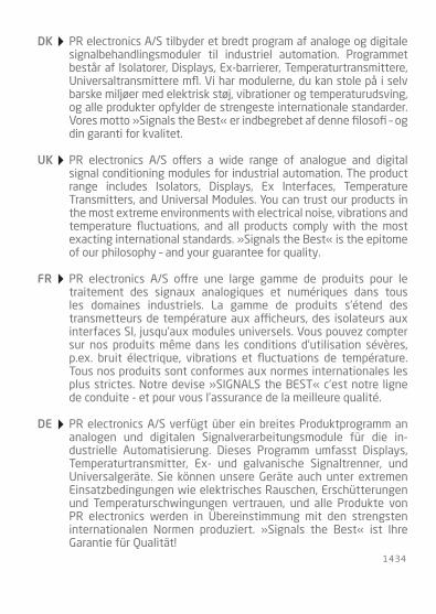
7 9 0 8 / 7 9 1 6S y s t e m 9 0 0 0 B a c k p l a n e H o n e y w e l l w i r i n g m a n u a l a n d I / O c a r d r e f e r e n c e l i s t
N o . 7 9 0 0 H W 1 0 1 - U K
1434
PR electronics A/S tilbyder et bredt program af analoge og digitale signalbehandlingsmoduler til industriel automation. Programmet består af Isolatorer, Displays, Ex-barrierer, Temperaturtransmittere, Universaltransmittere mfl. Vi har modulerne, du kan stole på i selv barske miljøer med elektrisk støj, vibrationer og temperaturudsving, og alle produkter opfylder de strengeste internationale standarder. Vores motto »Signals the Best« er indbegrebet af denne filosofi – og din garanti for kvalitet.
PR electronics A/S offers a wide range of analogue and digital signal conditioning modules for industrial automation. The product range includes Isolators, Displays, Ex Interfaces, Temperature Transmitters, and Universal Modules. You can trust our products in the most extreme environments with electrical noise, vibrations and temperature fluctuations, and all products comply with the most exacting international standards. »Signals the Best« is the epitome of our philosophy – and your guarantee for quality.
PR electronics A/S offre une large gamme de produits pour le traite ment des signaux analogiques et numériques dans tous les domaines industriels. La gamme de produits s’étend des transmetteurs de température aux afficheurs, des isolateurs aux interfaces SI, jusqu’aux modules universels. Vous pouvez compter sur nos produits même dans les conditions d’utilisation sévères, p.ex. bruit électrique, vibrations et fluctuations de température. Tous nos produits sont conformes aux normes internationales les plus strictes. Notre devise »SIGNALS the BEST« c’est notre ligne de conduite - et pour vous l’assurance de la meilleure qualité.
PR electronics A/S verfügt über ein breites Produktprogramm an analogen und digitalen Signalverarbeitungsmodule für die in-dustrielle Automatisierung. Dieses Programm umfasst Displays, Temperaturtransmitter, Ex- und galvanische Signaltrenner, und Universalgeräte. Sie können unsere Geräte auch unter extremen Einsatzbedingungen wie elektrisches Rauschen, Erschütterungen und Temperaturschwingungen vertrauen, und alle Produkte von PR electronics werden in Überein stimmung mit den strengsten internationalen Normen produziert. »Signals the Best« ist Ihre Garantie für Qualität!
DK
UK
FR
DE
7900HWM101-UK 1
SyStEm 9000 BacKplanEHOnEywEll wIRIng manUal
anD I/O caRD REFEREncE lISt
cOntEntSIntro ............................................................................................................................. 2
Supported Honeywell DCS / SIS systems & I/O cards ....................... 2Supply and status relay connections and Honeywell system cable connectors ........................................................ 3
Backplane to Honeywell Experion I/O card wiring ................................... 4CC-TAIX01/11 card, 16 modules - 16 x AI, PR 9106 1 ch............... 5CC-TAIX01/11 card, 8 modules - 16 x AI, PR 9106 2 ch. ................ 8CC-TAIX01/11 card, 16 modules - 16 x AI, PR 9113 1 ch............... 10CC-TAIX01/11 card, 8 modules - 16 x AI, PR 9113 2 ch. ................ 13CC-TAIX01/11 card, 16 modules - 16 x AO, PR 9107 1 ch. ............ 15CC-TAOX01/11 card, 8 modules - 16 x AO, PR 9107 2 ch. ............. 18Cx-TDIL01/11 card, 2 x 16 modules - 32 x DI, PR 9202 1 ch. ...... 20Cx-TDIL01/11 card, 16 modules - 32 x DI, PR 9202 2 ch. .............. 25Cx-TDOB01/11 card, 2 x 16 modules - 32 x DO, PR 9203 1 ch... 28Cx-TDOB01/11 card wiring, 32 x DO, PR 9203 2 ch. ........................ 33
Backplane to Honeywell SM-RUSIO I/O CARD wiring ............................. 36FC-IATO-R24 card wiring, 32 x uni. I/O, 1 ch. ........................................ 38FC-IATO-R24 card wiring, 32 x uni. I/O, 2 ch. ........................................ 43
Appendix ................................................................................................................... 46System cables for Honeywell Backplanes .............................................. 479106B AI I.S. isolation barrier - wiring connections ........................... 489107B AO I.S. isolation barrier - wiring connections ......................... 499113B AI I.S. isolation barrier - wiring connections ........................... 509116B AI I.S. isolation barrier - wiring connections ........................... 519202B AO I.S. isolation barrier - wiring connections ......................... 529203B AI I.S. isolation barrier - wiring connections ........................... 53
2 7900 HWM101-UK
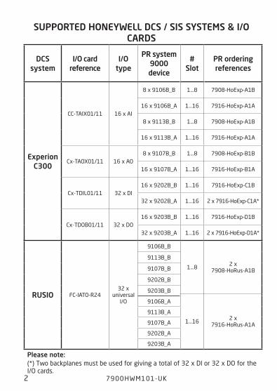
SUppORtED HOnEywEll DcS / SIS SyStEmS & I/O caRDS
please note: (*) Two backplanes must be used for giving a total of 32 x DI or 32 x DO for the I/O cards.
DcSsystem
I/O cardreference
I/O type
pR system 9000 device
#Slot
pR ordering references
Experionc300
CC-TAIX01/11 16 x AI
8 x 9106B_B 1...8 7908-HoExp-A1B
16 x 9106B_A 1...16 7916-HoExp-A1A
8 x 9113B_B 1...8 7908-HoExp-A1B
16 x 9113B_A 1...16 7916-HoExp-A1A
Cx-TAOX01/11 16 x AO8 x 9107B_B 1...8 7908-HoExp-B1B
16 x 9107B_A 1...16 7916-HoExp-B1A
Cx-TDIL01/11 32 x DI16 x 9202B_B 1...16 7916-HoExp-C1B
32 x 9202B_A 1...16 2 x 7916-HoExp-C1A*
Cx-TDOB01/11 32 x DO16 x 9203B_B 1...16 7916-HoExp-D1B
32 x 9203B_A 1...16 2 x 7916-HoExp-D1A*
RUSIO FC-IATO-R2432 x
universal I/O
9106B_B
1...8 2 x 7908-HoRus-A1B
9113B_B
9107B_B
9202B_B
9203B_B
1...16 2 x 7916-HoRus-A1A
9106B_A
9113B_A
9107B_A
9202B_A
9203B_A
IntRO
Supported Honeywell DcS / SIS systems & I/O cards
7900HWM101-UK 3
# 1
# 2
# 3
# 4
# 5
# 6
# 7
# 8
# 9
# 10
# 11
# 12
# 13
# 14
# 15
# 16
CN 1
CN 2
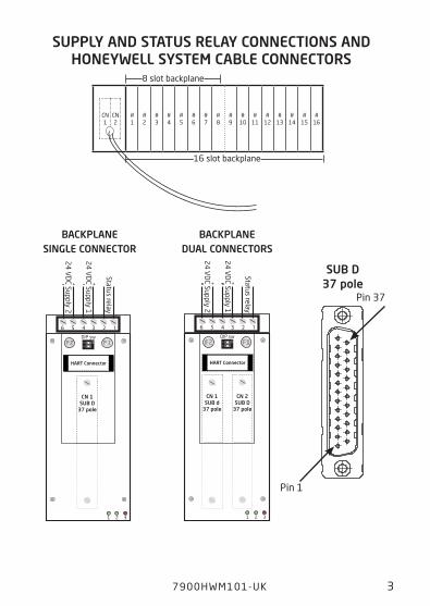
SUpply anD StatUS RElay cOnnEctIOnS anD HOnEywEll SyStEm caBlE cOnnEctORS
12
ON
++ --
1 2 3
F 1DIP sw
CN 2SUB D
37 pole
CN 1SUB d
37 pole
F 2
3 2 16 5 4
HART Connector
24
VD
C Supply 2
24
VD
C Supply 1
Status relay
BacKplanE DUal cOnnEctORS
12
ON
++ --
1 2 3
F 1DIP sw
CN 1SUB D
37 pole
F 2
3 2 16 5 4
HART Connector2
4 V
DC Supply 2
24
VD
C Supply 1
Status relay
BacKplanE SInglE cOnnEctOR
Pin 1
Pin 37
SUB D37 pole
Supply and status relay connections and Honeywell system cable connectors
8 slot backplane
16 slot backplane
4 7900 HWM101-UK
BacKplanE tO HOnEywEll ExpERIOn I/O caRD wIRIng
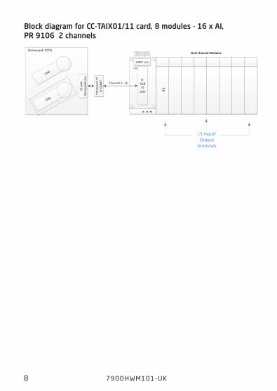
7900HWM101-UK 5
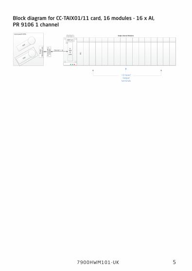
Block diagram for cc-taIx01/11 card, 16 modules - 16 x aI, pR 9106 1 channel
IOM
32 p
ole
Hone
ywel
l con
.
Channel 1- 16D-
SUB37
pole
Hone
ywel
l to
D-SU
B37
Single channel Modules
IOM
HART con
CN1
I.S Input/Output
terminals
Honeywell IOTA
#1
cc-taIx01/11 card, 16 modules - 16 x aI, pR 9106 1 ch.
6 7900 HWM101-UK
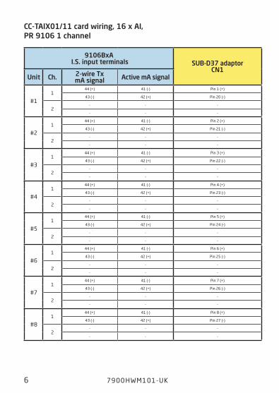
cc-taIx01/11 card wiring, 16 x aI, pR 9106 1 channel
9106Bxa I.S. input terminals SUB-D37 adaptor
cn1Unit ch. 2-wire tx
ma signal active ma signal
#11
44 (+) 41 (-) Pin 1 (+)
43 (-) 42 (+) Pin 20 (-)
2- - -
- - -
#21
44 (+) 41 (-) Pin 2 (+)
43 (-) 42 (+) Pin 21 (-)
2- - -
- - -
#31
44 (+) 41 (-) Pin 3 (+)
43 (-) 42 (+) Pin 22 (-)
2- - -
- - -
#41
44 (+) 41 (-) Pin 4 (+)
43 (-) 42 (+) Pin 23 (-)
2- - -
- - -
#51
44 (+) 41 (-) Pin 5 (+)
43 (-) 42 (+) Pin 24 (-)
2- - -
- - -
#61
44 (+) 41 (-) Pin 6 (+)
43 (-) 42 (+) Pin 25 (-)
2- - -
- - -
#71
44 (+) 41 (-) Pin 7 (+)
43 (-) 42 (+) Pin 26 (-)
2- - -
- - -
#81
44 (+) 41 (-) Pin 8 (+)
43 (-) 42 (+) Pin 27 (-)
2- - -
- - -
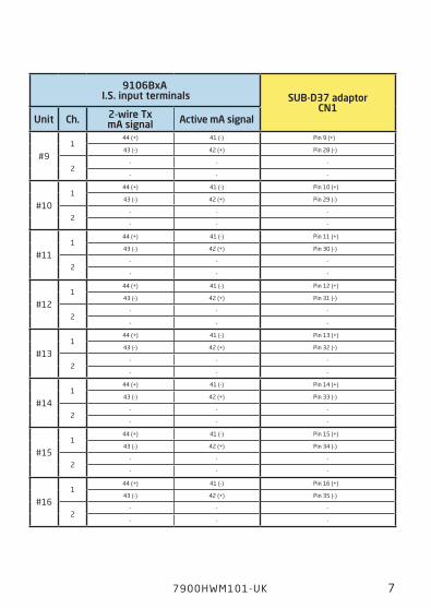
7900HWM101-UK 7
9106Bxa I.S. input terminals SUB-D37 adaptor
cn1Unit ch. 2-wire tx
ma signal active ma signal
#91
44 (+) 41 (-) Pin 9 (+)
43 (-) 42 (+) Pin 28 (-)
2- - -
- - -
#101
44 (+) 41 (-) Pin 10 (+)
43 (-) 42 (+) Pin 29 (-)
2- - -
- - -
#111
44 (+) 41 (-) Pin 11 (+)
43 (-) 42 (+) Pin 30 (-)
2- - -
- - -
#121
44 (+) 41 (-) Pin 12 (+)
43 (-) 42 (+) Pin 31 (-)
2- - -
- - -
#131
44 (+) 41 (-) Pin 13 (+)
43 (-) 42 (+) Pin 32 (-)
2- - -
- - -
#141
44 (+) 41 (-) Pin 14 (+)
43 (-) 42 (+) Pin 33 (-)
2- - -
- - -
#151
44 (+) 41 (-) Pin 15 (+)
43 (-) 42 (+) Pin 34 (-)
2- - -
- - -
#161
44 (+) 41 (-) Pin 16 (+)
43 (-) 42 (+) Pin 35 (-)
2- - -
- - -
8 7900 HWM101-UK
IOM
32 p
ole
Hone
ywel
l con
.Channel 1- 16
D-SUB37
poleHo
neyw
ell t
oD-
SUB3
7
Dual channel Modules
IOM
HART con
CN1
I.S Input/Output
terminals
Honeywell IOTA
#1
Block diagram for cc-taIx01/11 card, 8 modules - 16 x aI, pR 9106 2 channels
cc-taIx01/11 card, 8 modules - 16 x aI, pR 9106 2 ch.
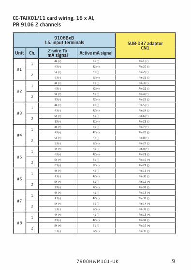
7900HWM101-UK 9
cc-taIx01/11 card wiring, 16 x aI, pR 9106 2 channels
9106BxB I.S. input terminals SUB-D37 adaptor
cn1Unit ch. 2-wire tx
ma signal active ma signal
#11
44 (+) 41 (-) Pin 1 (+)
43 (-) 42 (+) Pin 20 (-)
254 (+) 51 (-) Pin 2 (+)
53 (-) 52 (+) Pin 21 (-)
#21
44 (+) 41 (-) Pin 3 (+)
43 (-) 42 (+) Pin 22 (-)
254 (+) 51 (-) Pin 4 (+)
53 (-) 52 (+) Pin 23 (-)
#31
44 (+) 41 (-) Pin 5 (+)
43 (-) 42 (+) Pin 24 (-)
254 (+) 51 (-) Pin 6 (+)
53 (-) 52 (+) Pin 25 (-)
#41
44 (+) 41 (-) Pin 7 (+)
43 (-) 42 (+) Pin 26 (-)
254 (+) 51 (-) Pin 8 (+)
53 (-) 52 (+) Pin 27 (-)
#51
44 (+) 41 (-) Pin 9 (+)
43 (-) 42 (+) Pin 28 (-)
254 (+) 51 (-) Pin 10 (+)
53 (-) 52 (+) Pin 29 (-)
#61
44 (+) 41 (-) Pin 11 (+)
43 (-) 42 (+) Pin 30 (-)
254 (+) 51 (-) Pin 12 (+)
53 (-) 52 (+) Pin 31 (-)
#71
44 (+) 41 (-) Pin 13 (+)
43 (-) 42 (+) Pin 32 (-)
254 (+) 51 (-) Pin 14 (+)
53 (-) 52 (+) Pin 33 (-)
#81
44 (+) 41 (-) Pin 15 (+)
43 (-) 42 (+) Pin 34 (-)
254 (+) 51 (-) Pin 16 (+)
53 (-) 52 (+) Pin 35 (-)
10 7900 HWM101-UK
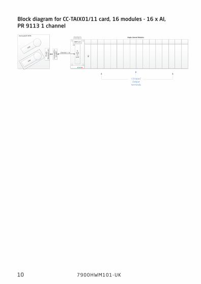
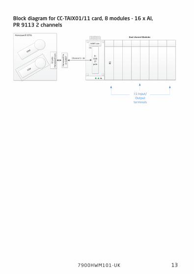
Block diagram for cc-taIx01/11 card, 16 modules - 16 x aI, pR 9113 1 channel
IOM
32 p
ole
Hone
ywel
l con
.
Channel 1- 16D-
SUB37
pole
Hone
ywel
l to
D-SU
B37
Single channel Modules
IOM
HART con
CN1
I.S Input/Output
terminals
Honeywell IOTA
#1
cc-taIx01/11 card, 16 modules - 16 x aI, pR 9113 1 ch.
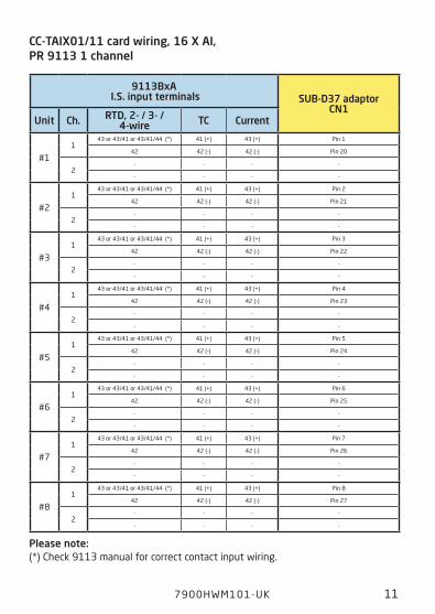
7900HWM101-UK 11
cc-taIx01/11 card wiring, 16 x aI, pR 9113 1 channel
9113Bxa I.S. input terminals SUB-D37 adaptor
cn1Unit ch. RtD, 2- / 3- /
4-wire tc current
#11
43 or 43/41 or 43/41/44 (*) 41 (+) 43 (+) Pin 1
42 42 (-) 42 (-) Pin 20
2- - - -
- - - -
#21
43 or 43/41 or 43/41/44 (*) 41 (+) 43 (+) Pin 2
42 42 (-) 42 (-) Pin 21
2- - - -
- - - -
#31
43 or 43/41 or 43/41/44 (*) 41 (+) 43 (+) Pin 3
42 42 (-) 42 (-) Pin 22
2- - - -
- - - -
#41
43 or 43/41 or 43/41/44 (*) 41 (+) 43 (+) Pin 4
42 42 (-) 42 (-) Pin 23
2- - - -
- - - -
#51
43 or 43/41 or 43/41/44 (*) 41 (+) 43 (+) Pin 5
42 42 (-) 42 (-) Pin 24
2- - - -
- - - -
#61
43 or 43/41 or 43/41/44 (*) 41 (+) 43 (+) Pin 6
42 42 (-) 42 (-) Pin 25
2- - - -
- - - -
#71
43 or 43/41 or 43/41/44 (*) 41 (+) 43 (+) Pin 7
42 42 (-) 42 (-) Pin 26
2- - - -
- - - -
#81
43 or 43/41 or 43/41/44 (*) 41 (+) 43 (+) Pin 8
42 42 (-) 42 (-) Pin 27
2- - - -
- - - -
please note: (*) Check 9113 manual for correct contact input wiring.
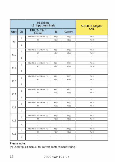
12 7900 HWM101-UK
9113Bxa I.S. input terminals SUB-D37 adaptor
cn1 Unit ch. RtD, 2- / 3- /
4-wire tc current
#91
43 or 43/41 or 43/41/44 (*) 41 (+) 43 (+) Pin 9
42 42 (-) 42 (-) Pin 28
2- - - -
- - - -
#101
43 or 43/41 or 43/41/44 (*) 41 (+) 43 (+) Pin 10
42 42 (-) 42 (-) Pin 29
2- - - -
- - - -
#111
43 or 43/41 or 43/41/44 (*) 41 (+) 43 (+) Pin 11
42 42 (-) 42 (-) Pin 30
2- - - -
- - - -
#121
43 or 43/41 or 43/41/44 (*) 41 (+) 43 (+) Pin 12
42 42 (-) 42 (-) Pin 31
2- - - -
- - - -
#131
43 or 43/41 or 43/41/44 (*) 41 (+) 43 (+) Pin 13
42 42 (-) 42 (-) Pin 32
2- - - -
- - - -
#141
43 or 43/41 or 43/41/44 (*) 41 (+) 43 (+) Pin 14
42 42 (-) 42 (-) Pin 33
2- - - -
- - - -
#151
43 or 43/41 or 43/41/44 (*) 41 (+) 43 (+) Pin 15
42 42 (-) 42 (-) Pin 34
2- - - -
- - - -
#161
43 or 43/41 or 43/41/44 (*) 41 (+) 43 (+) Pin 16
42 42 (-) 42 (-) Pin 35
2- - - -
- - - -
please note: (*) Check 9113 manual for correct contact input wiring.
7900HWM101-UK 13
IOM
32 p
ole
Hone
ywel
l con
.Channel 1- 16
D-SUB37
poleHo
neyw
ell t
oD-
SUB3
7
Dual channel Modules
IOM
HART con
CN1
I.S Input/Output
terminals
Honeywell IOTA
#1
Block diagram for cc-taIx01/11 card, 8 modules - 16 x aI, pR 9113 2 channels
cc-taIx01/11 card, 8 modules - 16 x aI, pR 9113 2 ch.
14 7900 HWM101-UK
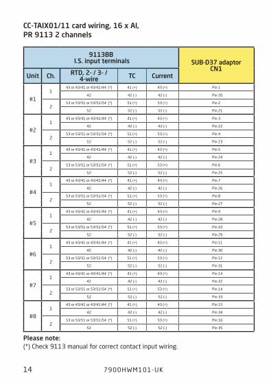
cc-taIx01/11 card wiring, 16 x aI, pR 9113 2 channels
9113BB I.S. input terminals SUB-D37 adaptor
cn1 Unit ch. RtD, 2- / 3- /
4-wire tc current
#11
43 or 43/41 or 43/41/44 (*) 41 (+) 43 (+) Pin 1
42 42 (-) 42 (-) Pin 20
253 or 53/51 or 53/51/54 (*) 51 (+) 53 (+) Pin 2
52 52 (-) 52 (-) Pin 21
#21
43 or 43/41 or 43/41/44 (*) 41 (+) 43 (+) Pin 3
42 42 (-) 42 (-) Pin 22
253 or 53/51 or 53/51/54 (*) 51 (+) 53 (+) Pin 4
52 52 (-) 52 (-) Pin 23
#31
43 or 43/41 or 43/41/44 (*) 41 (+) 43 (+) Pin 5
42 42 (-) 42 (-) Pin 24
253 or 53/51 or 53/51/54 (*) 51 (+) 53 (+) Pin 6
52 52 (-) 52 (-) Pin 25
#41
43 or 43/41 or 43/41/44 (*) 41 (+) 43 (+) Pin 7
42 42 (-) 42 (-) Pin 26
253 or 53/51 or 53/51/54 (*) 51 (+) 53 (+) Pin 8
52 52 (-) 52 (-) Pin 27
#51
43 or 43/41 or 43/41/44 (*) 41 (+) 43 (+) Pin 9
42 42 (-) 42 (-) Pin 28
253 or 53/51 or 53/51/54 (*) 51 (+) 53 (+) Pin 10
52 52 (-) 52 (-) Pin 29
#61
43 or 43/41 or 43/41/44 (*) 41 (+) 43 (+) Pin 11
42 42 (-) 42 (-) Pin 30
253 or 53/51 or 53/51/54 (*) 51 (+) 53 (+) Pin 12
52 52 (-) 52 (-) Pin 31
#71
43 or 43/41 or 43/41/44 (*) 41 (+) 43 (+) Pin 13
42 42 (-) 42 (-) Pin 32
253 or 53/51 or 53/51/54 (*) 51 (+) 53 (+) Pin 14
52 52 (-) 52 (-) Pin 33
#81
43 or 43/41 or 43/41/44 (*) 41 (+) 43 (+) Pin 15
42 42 (-) 42 (-) Pin 34
253 or 53/51 or 53/51/54 (*) 51 (+) 53 (+) Pin 16
52 52 (-) 52 (-) Pin 35
please note: (*) Check 9113 manual for correct contact input wiring.

7900HWM101-UK 15
Block diagram for cc-taOx01/11 card, 16 modules - 16 x aO, pR 9107 1 channel
IOM
32 p
ole
Hone
ywel
l con
.
Channel 1- 16D-
SUB37
pole
Hone
ywel
l to
D-SU
B37
Single channel Modules
IOM
HART con
CN1
I.S Input/Output
terminals
Honeywell IOTA
#1
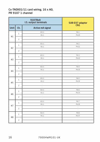
cc-taIx01/11 card, 16 modules - 16 x aO, pR 9107 1 ch.
16 7900 HWM101-UK
cx-taOx01/11 card wiring, 16 x aO, pR 9107 1 channel
9107Bxa I.S. output terminals SUB-D37 adaptor
cn1Unit ch. active ma signal
#11
42 (+) Pin 1
41 (-) Pin 20
2- -
- -
#21
42 (+) Pin 2
41 (-) Pin 21
2- -
- -
#31
42 (+) Pin 3
41 (-) Pin 22
2- -
- -
#41
42 (+) Pin 4
41 (-) Pin 23
2- -
- -
#51
42 (+) Pin 5
41 (-) Pin 24
2- -
- -
#61
42 (+) Pin 6
41 (-) Pin 25
2- -
- -
#71
42 (+) Pin 7
41 (-) Pin 26
2- -
- -
#81
42 (+) Pin 8
41 (-) Pin 27
2- -
- -
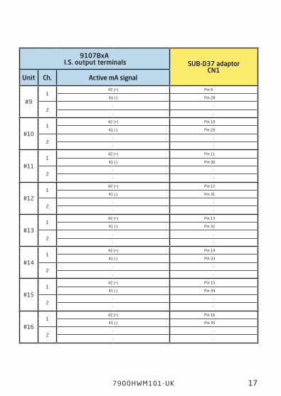
7900HWM101-UK 17
9107Bxa I.S. output terminals SUB-D37 adaptor
cn1Unit ch. active ma signal
#91
42 (+) Pin 9
41 (-) Pin 28
2- -
- -
#101
42 (+) Pin 10
41 (-) Pin 29
2- -
- -
#111
42 (+) Pin 11
41 (-) Pin 30
2- -
- -
#121
42 (+) Pin 12
41 (-) Pin 31
2- -
- -
#131
42 (+) Pin 13
41 (-) Pin 32
2- -
- -
#141
42 (+) Pin 14
41 (-) Pin 33
2- -
- -
#151
42 (+) Pin 15
41 (-) Pin 34
2- -
- -
#161
42 (+) Pin 16
41 (-) Pin 35
2- -
- -
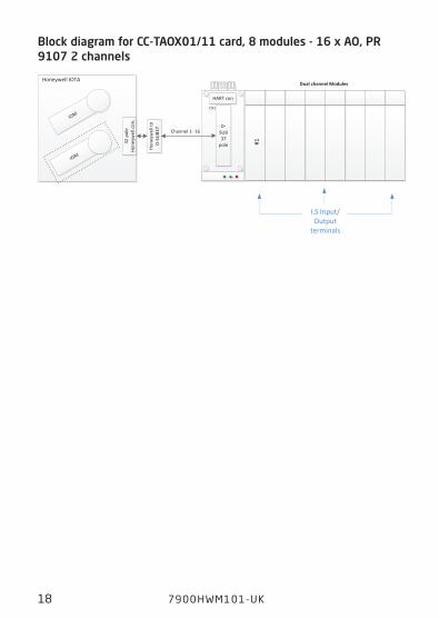
18 7900 HWM101-UK
IOM
32 p
ole
Hone
ywel
l con
.Channel 1- 16
D-SUB37
poleHo
neyw
ell t
oD-
SUB3
7
Dual channel Modules
IOM
HART con
CN1
I.S Input/Output
terminals
Honeywell IOTA
#1
Block diagram for cc-taOx01/11 card, 8 modules - 16 x aO, pR 9107 2 channels
cc-taOx01/11 card, 8 modules - 16 x aO, pR 9107 2 ch.
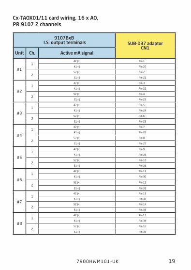
7900HWM101-UK 19
cx-taOx01/11 card wiring, 16 x aO, pR 9107 2 channels
9107BxB I.S. output terminals SUB-D37 adaptor
cn1Unit ch. active ma signal
#11
42 (+) Pin 1
41 (-) Pin 20
252 (+) Pin 2
51 (-) Pin 21
#21
42 (+) Pin 3
41 (-) Pin 22
252 (+) Pin 4
51 (-) Pin 23
#31
42 (+) Pin 5
41 (-) Pin 24
252 (+) Pin 6
51 (-) Pin 25
#4
142 (+) Pin 7
41 (-) Pin 26
252 (+) Pin 8
51 (-) Pin 27
#51
42 (+) Pin 9
41 (-) Pin 28
252 (+) Pin 10
51 (-) Pin 29
#6
142 (+) Pin 11
41 (-) Pin 30
252 (+) Pin 12
51 (-) Pin 31
#71
42 (+) Pin 13
41 (-) Pin 32
252 (+) Pin 14
51 (-) Pin 33
#81
42 (+) Pin 15
41 (-) Pin 34
252 (+) Pin 16
51 (-) Pin 35
20 7900 HWM101-UK
Block diagram for cx-tDIl01/11 card, 2 x16 modules - 32 x DI, pR 9202 1 channel
IOM
32 p
ole
Hone
ywel
l con
.32
pol
e Ho
neyw
ell c
on.
Channel 1- 16
Channel 17 - 32
D-SUB37
pole
D-SUB37
pole
Hone
ywel
l to
D-SU
B37
Hone
ywel
l to
D-SU
B37
Single Channel modules
Single Channel modules
IOM I.S Input/Output
terminals
I.S Input/Output
terminals
CN1
CN1
Honeywell IOTA
#2#1
cx-tDIl01/11 card, 2 x 16 modules - 32 x DI, pR 9202 1 ch.
7900HWM101-UK 21
cx-tDIl01/11 card wiring, 32 x DI, pR 9202 1 channel, Backplane #1
9202Bxa I.S. input terminals SUB-D37 adaptor
cn1Unit ch. namUR sensor contact signal
#11
44 (+) 44 or 43 or 43/41 (*) Pin 1
42 (-) 42 Pin 20
2- - -
- - -
#21
44 (+) 44 or 43 or 43/41 (*) Pin 2
42 (-) 42 Pin 21
2- - -
- - -
#31
44 (+) 44 or 43 or 43/41 (*) Pin 3
42 (-) 42 Pin 22
2- - -
- - -
#41
44 (+) 44 or 43 or 43/41 (*) Pin 4
42 (-) 42 Pin 23
2- - -
- - -
#51
44 (+) 44 or 43 or 43/41 (*) Pin 5
42 (-) 42 Pin 24
2- - -
- - -
#61
44 (+) 44 or 43 or 43/41 (*) Pin 6
42 (-) 42 Pin 25
2- - -
- - -
#71
44 (+) 44 or 43 or 43/41 (*) Pin 7
42 (-) 42 Pin 26
2- - -
- - -
#81
44 (+) 44 or 43 or 43/41 (*) Pin 8
42 (-) 42 Pin 27
2- - -
- - -
22 7900 HWM101-UK
please note: (*) Check 9202 manual for correct output signal wiring.
9202Bxa I.S. Input terminals SUB-D37 adaptor
cn1Unit ch. namUR sensor contact signal
#91
44 (+) 44 or 43 or 43/41 (*) Pin 9
42 (-) 42 Pin 28
2- - -
- - -
#101
44 (+) 44 or 43 or 43/41 (*) Pin 10
42 (-) 42 Pin 29
2- - -
- - -
#111
44 (+) 44 or 43 or 43/41 (*) Pin 11
42 (-) 42 Pin 30
2- - -
- - -
#121
44 (+) 44 or 43 or 43/41 (*) Pin 12
42 (-) 42 Pin 31
2- - -
- - -
#131
44 (+) 44 or 43 or 43/41 (*) Pin 13
42 (-) 42 Pin 32
2- - -
- - -
#141
44 (+) 44 or 43 or 43/41 (*) Pin 14
42 (-) 42 Pin 33
2- - -
- - -
#151
44 (+) 44 or 43 or 43/41 (*) Pin 15
42 (-) 42 Pin 34
2- - -
- - -
#161
44 (+) 44 or 43 or 43/41 (*) Pin 16
42 (-) 42 Pin 35
2- - -
- - -
7900HWM101-UK 23
cx-tDIl01/11 card wiring, 32 x DI, pR 9202 1 channel, Backplane #2
9202Bxa I.S. input terminals SUB-D37 adaptor
cn1Unit ch. namUR sensor contact signal
#11
44 (+) 44 or 43 or 43/41 (*) Pin 1
42 (-) 42 Pin 20
2- - -
- - -
#21
44 (+) 44 or 43 or 43/41 (*) Pin 2
42 (-) 42 Pin 21
2- - -
- - -
#31
44 (+) 44 or 43 or 43/41 (*) Pin 3
42 (-) 42 Pin 22
2- - -
- - -
#41
44 (+) 44 or 43 or 43/41 (*) Pin 4
42 (-) 42 Pin 23
2- - -
- - -
#51
44 (+) 44 or 43 or 43/41 (*) Pin 5
42 (-) 42 Pin 24
2- - -
- - -
#61
44 (+) 44 or 43 or 43/41 (*) Pin 6
42 (-) 42 Pin 25
2- - -
- - -
#71
44 (+) 44 or 43 or 43/41 (*) Pin 7
42 (-) 42 Pin 26
2- - -
- - -
#81
44 (+) 44 or 43 or 43/41 (*) Pin 8
42 (-) 42 Pin 27
2- - -
- - -

24 7900 HWM101-UK
9202Bxa I.S. input terminals SUB-D37 adaptor
cn1Unit ch. namUR sensor contact signal
#91
44 (+) 44 or 43 or 43/41 (*) Pin 9
42 (-) 42 Pin 28
2- - -
- - -
#101
44 (+) 44 or 43 or 43/41 (*) Pin 10
42 (-) 42 Pin 29
2- - -
- - -
#111
44 (+) 44 or 43 or 43/41 (*) Pin 11
42 (-) 42 Pin 30
2- - -
- - -
#121
44 (+) 44 or 43 or 43/41 (*) Pin 12
42 (-) 42 Pin 31
2- - -
- - -
#131
44 (+) 44 or 43 or 43/41 (*) Pin 13
42 (-) 42 Pin 32
2- - -
- - -
#141
44 (+) 44 or 43 or 43/41 (*) Pin 14
42 (-) 42 Pin 33
2- - -
- - -
#151
44 (+) 44 or 43 or 43/41 (*) Pin 15
42 (-) 42 Pin 34
2- - -
- - -
#161
44 (+) 44 or 43 or 43/41 (*) Pin 16
42 (-) 42 Pin 35
2- - -
- - -
please note: (*) Check 9202 manual for correct output signal wiring.
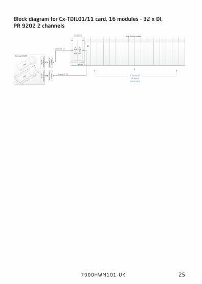
7900HWM101-UK 25
Block diagram for cx-tDIl01/11 card, 16 modules - 32 x DI, pR 9202 2 channels
IOM
32 p
ole
Hone
ywel
l con
.32
pol
e Ho
neyw
ell c
on.
Channel 1- 16D-
SUB37
pole
D-SUB37
pole
Hone
ywel
l to
D-SU
B37
Hone
ywel
l to
D-SU
B37 Channel 2 - 32
Dual Channel modules
IOM
CN1 CN2
Honeywell IOTA
#1
I.S Input/Output
terminals
cx-tDIl01/11 card, 16 modules - 32 x DI, pR 9202 2 ch.
26 7900 HWM101-UK
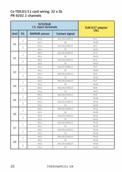
cx-tDIl01/11 card wiring, 32 x DI, pR 9202 2 channels
9202BxB I.S. input terminals SUB-D37 adaptor
cn1Unit ch. namUR sensor contact signal
#11
44 (+) 44 or 43 or 43/41 (*) Pin 1
42 (-) 42 Pin 20
254 (+) 54 or 53 or 53/51 (*) Pin 2
52 (-) 52 Pin 21
#21
44 (+) 44 or 43 or 43/41 (*) Pin 3
42 (-) 42 Pin 22
254 (+) 54 or 53 or 53/51 (*) Pin 4
52 (-) 52 Pin 23
#31
44 (+) 44 or 43 or 43/41 (*) Pin 5
42 (-) 42 Pin 24
254 (+) 54 or 53 or 53/51 (*) Pin 6
52 (-) 52 Pin 25
#41
44 (+) 44 or 43 or 43/41 (*) Pin 7
42 (-) 42 Pin 26
254 (+) 54 or 53 or 53/51 (*) Pin 8
52 (-) 52 Pin 27
#51
44 (+) 44 or 43 or 43/41 (*) Pin 9
42 (-) 42 Pin 28
254 (+) 54 or 53 or 53/51 (*) Pin 10
52 (-) 52 Pin 29
#61
44 (+) 44 or 43 or 43/41 (*) Pin 11
42 (-) 42 Pin 30
254 (+) 54 or 53 or 53/51 (*) Pin 12
52 (-) 52 Pin 31
#71
44 (+) 44 or 43 or 43/41 (*) Pin 13
42 (-) 42 Pin 32
254 (+) 54 or 53 or 53/51 (*) Pin 14
52 (-) 52 Pin 33
#81
44 (+) 44 or 43 or 43/41 (*) Pin 15
42 (-) 42 Pin 34
254 (+) 54 or 53 or 53/51 (*) Pin 16
52 (-) 52 Pin 35
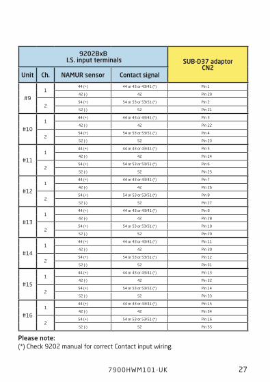
7900HWM101-UK 27
9202BxB I.S. input terminals SUB-D37 adaptor
cn2Unit ch. namUR sensor contact signal
#91
44 (+) 44 or 43 or 43/41 (*) Pin 1
42 (-) 42 Pin 20
254 (+) 54 or 53 or 53/51 (*) Pin 2
52 (-) 52 Pin 21
#101
44 (+) 44 or 43 or 43/41 (*) Pin 3
42 (-) 42 Pin 22
254 (+) 54 or 53 or 53/51 (*) Pin 4
52 (-) 52 Pin 23
#111
44 (+) 44 or 43 or 43/41 (*) Pin 5
42 (-) 42 Pin 24
254 (+) 54 or 53 or 53/51 (*) Pin 6
52 (-) 52 Pin 25
#121
44 (+) 44 or 43 or 43/41 (*) Pin 7
42 (-) 42 Pin 26
254 (+) 54 or 53 or 53/51 (*) Pin 8
52 (-) 52 Pin 27
#131
44 (+) 44 or 43 or 43/41 (*) Pin 9
42 (-) 42 Pin 28
254 (+) 54 or 53 or 53/51 (*) Pin 10
52 (-) 52 Pin 29
#141
44 (+) 44 or 43 or 43/41 (*) Pin 11
42 (-) 42 Pin 30
254 (+) 54 or 53 or 53/51 (*) Pin 12
52 (-) 52 Pin 31
#151
44 (+) 44 or 43 or 43/41 (*) Pin 13
42 (-) 42 Pin 32
254 (+) 54 or 53 or 53/51 (*) Pin 14
52 (-) 52 Pin 33
#161
44 (+) 44 or 43 or 43/41 (*) Pin 15
42 (-) 42 Pin 34
254 (+) 54 or 53 or 53/51 (*) Pin 16
52 (-) 52 Pin 35
please note: (*) Check 9202 manual for correct Contact input wiring.
28 7900 HWM101-UK
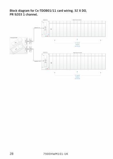
Block diagram for cx-tDOB01/11 card wiring, 32 x DO, pR 9203 1 channel,
IOM
32 p
ole
Hone
ywel
l con
.32
pol
e Ho
neyw
ell c
on.
Channel 1- 16
Channel 17 - 32
D-SUB37
pole
D-SUB37
pole
Hone
ywel
l to
D-SU
B37
Hone
ywel
l to
D-SU
B37
Single Channel modules
Single Channel modules
IOM I.S Input/Output
terminals
I.S Input/Output
terminals
CN1
CN1
Honeywell IOTA
#2#1
cx-tDOB01/11 card, 2 x 16 modules - 32 x DO, pR 9203 1 ch.
7900HWM101-UK 29
cx-tDOB01/11 card wiring, 32 x DO, pR 9203 1 channel, Backplane #1
9203Bxa I.S. output terminals SUB-D37 adaptor
cn1Unit ch. Output (+) signal Return (-) signal
#11 42, 43, 44 (*) 41
Pin 1
Pin 20
2 - --
-
#21 42, 43, 44 (*) 41
Pin 2
Pin 21
2 - --
-
#31 42, 43, 44 (*) 41
Pin 3
Pin 22
2 - -
#41 42, 43, 44 (*) 41
Pin 4
Pin 23
2 - --
-
#51 42, 43, 44 (*) 41
Pin 5
Pin 24
2 - --
-
#61 42, 43, 44 (*) 41
Pin 6
Pin 25
2 - --
-
#71 42, 43, 44 (*) 41
Pin 7
Pin 26
2 - --
-
#81 42, 43, 44 (*) 41
Pin 8
Pin 27
2 - --
-
30 7900 HWM101-UK
9203Bxa I.S. output terminals SUB-D37 adaptor
cn1 Unit ch. Output (+) signal Return (-) signal
#91 42, 43, 44 (*) 41
Pin 9
Pin 28
2 - --
-
#101 42, 43, 44 (*) 41
Pin 10
Pin 29
2 - --
-
#111 42, 43, 44 (*) 41
Pin 11
Pin 30
2 - --
-
#121 42, 43, 44 (*) 41
Pin 12
Pin 31
2 - --
-
#131 42, 43, 44 (*) 41
Pin 13
Pin 32
2 - --
-
#141 42, 43, 44 (*) 41
Pin 14
Pin 33
2 - --
-
#151 42, 43, 44 (*) 41
Pin 15
Pin 34
2 - --
-
#161 42, 43, 44 (*) 41
Pin 16
Pin 35
2 - --
-
please note: (*) Check 9203 manual for correct output signal wiring.
7900HWM101-UK 31
cx-tDOB01/11 card wiring, 32 x DO, pR 9203 1 channel, Backplane #2
9203Bxa I.S. output terminals SUB-D37 adaptor
cn1Unit ch. Output (+) signal Return (-) signal
#11 42, 43, 44 (*) 41
Pin 1
Pin 20
2 - --
-
#21 42, 43, 44 (*) 41
Pin 2
Pin 21
2 - --
-
#31 42, 43, 44 (*) 41
Pin 3
Pin 22
2 - --
-
#41 42, 43, 44 (*) 41
Pin 4
Pin 23
2 - --
-
#51 42, 43, 44 (*) 41
Pin 5
Pin 24
2 - --
-
#61 42, 43, 44 (*) 41
Pin 6
Pin 25
2 - --
-
#71 42, 43, 44 (*) 41
Pin 7
Pin 26
2 - --
-
#81 42, 43, 44 (*) 41
Pin 8
Pin 27
2 - --
-

32 7900 HWM101-UK
9203Bxa I.S. output terminals SUB-D37 adaptor
cn1Unit ch. Output (+) signal Return (-) signal
#91 42, 43, 44 (*) 41
Pin 9
Pin 28
2 - --
-
#101 42, 43, 44 (*) 41
Pin 10
Pin 29
2 - --
-
#111 42, 43, 44 (*) 41
Pin 11
Pin 30
2 - --
-
#121 42, 43, 44 (*) 41
Pin 12
Pin 31
2 - --
-
#131 42, 43, 44 (*) 41
Pin 13
Pin 32
2 - --
-
#141 42, 43, 44 (*) 41
Pin 14
Pin 33
2 - --
-
#151 42, 43, 44 (*) 41
Pin 15
Pin 34
2 - --
-
#161 42, 43, 44 (*) 41
Pin 16
Pin 35
2 - --
-
please note: (*) Check 9203 manual for correct output signal wiring.
7900HWM101-UK 33
IOM
32 p
ole
Hone
ywel
l con
.32
pol
e Ho
neyw
ell c
on.
Channel 1- 16D-
SUB37
pole
D-SUB37
pole
Hone
ywel
l to
D-SU
B37
Hone
ywel
l to
D-SU
B37 Channel 2 - 32
Dual Channel modules
IOM
CN1 CN2
Honeywell IOTA
#1
I.S Input/Output
terminals
Block diagram for cx-tDOB01/11 card wiring, 32 x DO, pR 9203 2 channels
cx-tDOB01/11 card wiring, 32 x DO, pR 9203 2 ch.
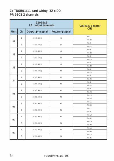
34 7900 HWM101-UK
cx-tDOB01/11 card wiring, 32 x DO, pR 9203 2 channels
9203BxB I.S. output terminals SUB-D37 adaptor
cn1Unit ch. Output (+) signal Return (-) signal
#11 42, 43, 44 (*) 41
Pin 1
Pin 20
2 52, 53, 54 (*) 51Pin 2
Pin 21
#21 42, 43, 44 (*) 41
Pin 3
Pin 22
2 52, 53, 54 (*) 51Pin 4
Pin 23
#31 42, 43, 44 (*) 41
Pin 5
Pin 24
2 52, 53, 54 (*) 51Pin 6
Pin 25
#41 42, 43, 44 (*) 41
Pin 7
Pin 26
2 52, 53, 54 (*) 51Pin 8
Pin 27
#51 42, 43, 44 (*) 41
Pin 9
Pin 28
2 52, 53, 54 (*) 51Pin 10
Pin 29
#61 42, 43, 44 (*) 41
Pin 11
Pin 30
2 52, 53, 54 (*) 51Pin 12
Pin 31
#71 42, 43, 44 (*) 41
Pin 13
Pin 32
2 52, 53, 54 (*) 51Pin 14
Pin 33
#81 42, 43, 44 (*) 41
Pin 15
Pin 34
2 52, 53, 54 (*) 51Pin 16
Pin 35
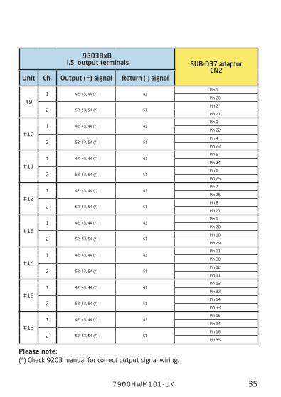
7900HWM101-UK 35
9203BxB I.S. output terminals SUB-D37 adaptor
cn2Unit ch. Output (+) signal Return (-) signal
#91 42, 43, 44 (*) 41
Pin 1
Pin 20
2 52, 53, 54 (*) 51Pin 2
Pin 21
#101 42, 43, 44 (*) 41
Pin 3
Pin 22
2 52, 53, 54 (*) 51Pin 4
Pin 23
#111 42, 43, 44 (*) 41
Pin 5
Pin 24
2 52, 53, 54 (*) 51Pin 6
Pin 25
#121 42, 43, 44 (*) 41
Pin 7
Pin 26
2 52, 53, 54 (*) 51Pin 8
Pin 27
#131 42, 43, 44 (*) 41
Pin 9
Pin 28
2 52, 53, 54 (*) 51Pin 10
Pin 29
#141 42, 43, 44 (*) 41
Pin 11
Pin 30
2 52, 53, 54 (*) 51Pin 12
Pin 31
#151 42, 43, 44 (*) 41
Pin 13
Pin 32
2 52, 53, 54 (*) 51Pin 14
Pin 33
#161 42, 43, 44 (*) 41
Pin 15
Pin 34
2 52, 53, 54 (*) 51Pin 16
Pin 35
please note: (*) Check 9203 manual for correct output signal wiring.
36 7900 HWM101-UK
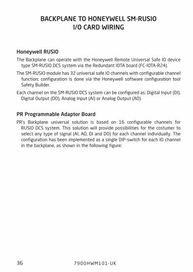
BacKplanE tO HOnEywEll Sm-RUSIO I/O caRD wIRIng
Honeywell RUSIOThe Backplane can operate with the Honeywell Remote Universal Safe IO device
type SM-RUSIO DCS system via the Redundant IOTA board (FC-IOTA-R24).
The SM-RUSIO module has 32 universal safe IO channels with configurable channel function; configuration is done via the Honeywell software configuration tool Safety Builder.
Each channel on the SM-RUSIO DCS system can be configured as: Digital Input (DI), Digital Output (DO), Analog Input (AI) or Analog Output (AO).
pR programmable adaptor Board PR’s Backplane universal solution is based on 16 configurable channels for
RUSIO DCS system. This solution will provide possibilities for the costumer to select any type of signal (AI, AO, DI and DO) for each channel individually. The configuration has been implemented as a single DIP-switch for each IO channel in the backplane, as shown in the following figure:
7900HWM101-UK 37
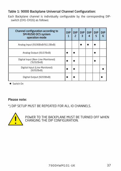
channel configuration according to Sm-RUSIO DcS system
operation mode
DIp 1
DIp 2
DIp 3
DIp 4
DIp 5
DIp 6
Analog Input (9106BxB/9113BxB) • • •Analog Output (9107BxB) • • •
Digital Input (Non-Line-Monitored) (’9202BxB) • • •
Digital Input (Line-Monitored)(9202BxB) • • •
Digital Output (9203BxB) • • • • Switch On
please note:
*) DIP SETUP MUST BE REPEATED FOR ALL IO CHANNELS.
POWER TO THE BACKPLANE MUST BE TURNED OFF WHEN CHANGING THE DIP CONFIGURATION.
table 1: 9000 Backplane Universal channel configuration:Each Backplane channel is individually configurable by the corresponding DIP-
switch (CH1-CH16) as follows:
38 7900 HWM101-UK
IOM
32 p
ole
Hone
ywel
l con
.32
pol
e Ho
neyw
ell c
on.
Channel 1- 16
Channel 17 - 32
D-SUB37
pole
D-SUB37
pole
Hone
ywel
l to
D-SU
B37
Hone
ywel
l to
D-SU
B37
Single Channel modules
Single Channel modules
IOM I.S Input/Output
terminals
I.S Input/Output
terminals
CN1
CN1
#1#1
Honeywell IOTA
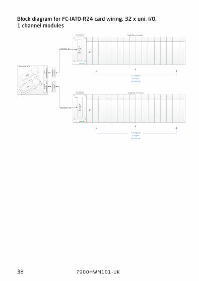
Block diagram for Fc-IatO-R24 card wiring, 32 x uni. I/O, 1 channel modules
Fc-IatO-R24 card wiring, 32 x uni. I/O, 1 ch.
7900HWM101-UK 39
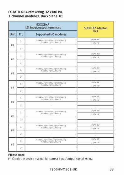
Fc-IatO-R24 card wiring, 32 x uni. I/O, 1 channel modules, Backplane #1
9xxxBxa I.S. input/output terminals SUB-D37 adaptor
cn1Unit ch. Supported I/O modules
#11 9106BxA (*); 9107BxA (*); 9202BxA (*)
9203BxA (*); 9113BxA (*)
(+) Pin 37*
( -) Pin 19*
2 --
-
#21 9106BxA (*); 9107BxA (*); 9202BxA (*)
9203BxA (*); 9113BxA (*)
(+) Pin 36*
( -) Pin 18*
2 --
-
#31 9106BxA (*); 9107BxA (*); 9202BxA (*)
9203BxA (*); 9113BxA (*)
(+) Pin 35*
( -) Pin 17*
2 --
-
#41 9106BxA (*); 9107BxA (*); 9202BxA (*)
9203BxA (*); 9113BxA (*)
(+) Pin 34*
( -) Pin 16*
2 --
-
#51 9106BxA (*); 9107BxA (*); 9202BxA (*)
9203BxA (*); 9113BxA (*)
(+) Pin 33*
( -) Pin 15*
2 --
-
#61 9106BxA (*); 9107BxA (*); 9202BxA (*)
9203BxA (*); 9113BxA (*)
(+) Pin 32*
( -) Pin 14*
2 --
-
#71 9106BxA (*); 9107BxA (*); 9202BxA (*)
9203BxA (*); 9113BxA (*)
(+) Pin 31*
( -) Pin 13*
2 --
-
#81 9106BxA (*); 9107BxA (*); 9202BxA (*)
9203BxA (*); 9113BxA (*)
(+) Pin 30*
( -) Pin 12*
2 --
-
please note: (*) Check the device manual for correct input/output signal wiring.
40 7900 HWM101-UK
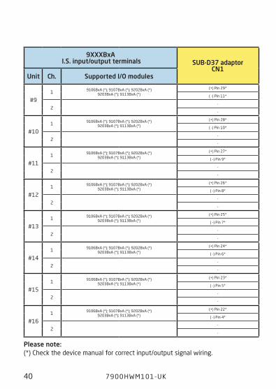
9xxxBxa I.S. input/output terminals SUB-D37 adaptor
cn1Unit ch. Supported I/O modules
#91 9106BxA (*); 9107BxA (*); 9202BxA (*)
9203BxA (*); 9113BxA (*)
(+) Pin 29*
( -) Pin 11*
2-
-
#101 9106BxA (*); 9107BxA (*); 9202BxA (*)
9203BxA (*); 9113BxA (*)
(+) Pin 28*
( -) Pin 10*
2-
-
#111 9106BxA (*); 9107BxA (*); 9202BxA (*)
9203BxA (*); 9113BxA (*)
(+) Pin 27*
( -) Pin 9*
2-
-
#121 9106BxA (*); 9107BxA (*); 9202BxA (*)
9203BxA (*); 9113BxA (*)
(+) Pin 26*
( -) Pin 8*
2-
-
#131 9106BxA (*); 9107BxA (*); 9202BxA (*)
9203BxA (*); 9113BxA (*)
(+) Pin 25*
( -) Pin 7*
2-
-
#141 9106BxA (*); 9107BxA (*); 9202BxA (*)
9203BxA (*); 9113BxA (*)
(+) Pin 24*
( -) Pin 6*
2-
-
#151 9106BxA (*); 9107BxA (*); 9202BxA (*)
9203BxA (*); 9113BxA (*)
(+) Pin 23*
( -) Pin 5*
2-
-
#161 9106BxA (*); 9107BxA (*); 9202BxA (*)
9203BxA (*); 9113BxA (*)
(+) Pin 22*
( -) Pin 4*
2-
-
please note: (*) Check the device manual for correct input/output signal wiring.

7900HWM101-UK 41
Fc-IatO-R24 card wiring, 32 x uni. I/O, 1 channel modules, Backplane #2
9xxxBxa I.S. input/output terminals SUB-D37 adaptor
cn1Unit ch. Supported I/O modules
#11 9106BxA (*); 9107BxA (*); 9202BxA (*)
9203BxA (*); 9113BxA (*); 9116B (*, **)
(+) Pin 37*
( -) Pin 19*
2 --
-
#21 9106BxA (*); 9107BxA (*); 9202BxA (*)
9203BxA (*); 9113BxA (*); 9116B (*, **)
(+) Pin 36*
( -) Pin 18*
2 --
-
#31 9106BxA (*); 9107BxA (*); 9202BxA (*)
9203BxA (*); 9113BxA (*); 9116B (*, **)
(+) Pin 35*
( -) Pin 17*
2 --
-
#41 9106BxA (*); 9107BxA (*); 9202BxA (*)
9203BxA (*); 9113BxA (*); 9116B (*, **)
(+) Pin 34*
( -) Pin 16*
2 --
-
#51 9106BxA (*); 9107BxA (*); 9202BxA (*)
9203BxA (*); 9113BxA (*); 9116B (*, **)
(+) Pin 33*
( -) Pin 15*
2 --
-
#61 9106BxA (*); 9107BxA (*); 9202BxA (*)
9203BxA (*); 9113BxA (*); 9116B (*, **)
(+) Pin 32*
( -) Pin 14*
2 --
-
#71 9106BxA (*); 9107BxA (*); 9202BxA (*)
9203BxA (*); 9113BxA (*); 9116B (*, **)
(+) Pin 31*
( -) Pin 13*
2 --
-
#81 9106BxA (*); 9107BxA (*); 9202BxA (*)
9203BxA (*); 9113BxA (*); 9116B (*, **)
(+) Pin 30*
( -) Pin 12*
2 --
-
please note: (*) Check the device manual for correct input/output signal wiring.
42 7900 HWM101-UK
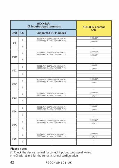
9xxxBxa I.S. input/output terminals SUB-D37 adaptor
cn1Unit ch. Supported I/O modules
#91 9106BxA (*); 9107BxA (*); 9202BxA (*)
9203BxA (*); 9113BxA (*); 9116B (*, **)
(+) Pin 29*
( -) Pin 11*
2 --
-
#101 9106BxA (*); 9107BxA (*); 9202BxA (*)
9203BxA (*); 9113BxA (*); 9116B (*, **)
(+) Pin 28*
( -) Pin 10*
2 --
-
#111 9106BxA (*); 9107BxA (*); 9202BxA (*)
9203BxA (*); 9113BxA (*); 9116B (*, **)
(+) Pin 27*
( -) Pin 9*
2 --
-
#121 9106BxA (*); 9107BxA (*); 9202BxA (*)
9203BxA (*); 9113BxA (*); 9116B (*, **)
(+) Pin 26*
( -) Pin 8*
2 --
-
#131 9106BxA (*); 9107BxA (*); 9202BxA (*)
9203BxA (*); 9113BxA (*); 9116B (*, **)
(+) Pin 25*
( -) Pin 7*
2 --
-
#141 9106BxA (*); 9107BxA (*); 9202BxA (*)
9203BxA (*); 9113BxA (*); 9116B (*, **)
(+) Pin 24*
( -) Pin 6*
2 --
-
#151 9106BxA (*); 9107BxA (*); 9202BxA (*)
9203BxA (*); 9113BxA (*); 9116B (*, **)
(+) Pin 23*
( -) Pin 5*
2 --
-
#161 9106BxA (*); 9107BxA (*); 9202BxA (*)
9203BxA (*); 9113BxA (*); 9116B (*, **)
(+) Pin 22*
( -) Pin 4*
2 --
-
please note: (*) Check the device manual for correct input/output signal wiring. (**) Check table 1 for the correct channel configuration.

7900HWM101-UK 43
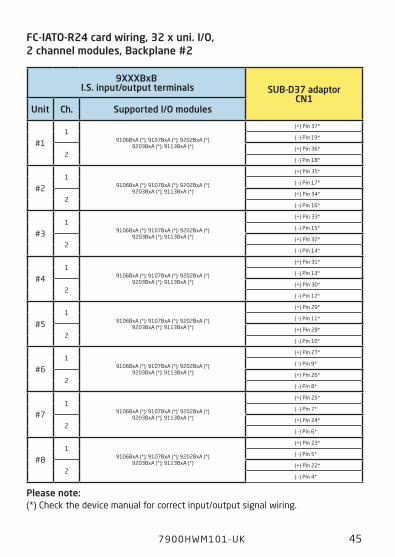
Block diagram for Fc-IatO-R24 card wiring, 32 x uni. I/O, 2 channel modules
IOM
32 p
ole
Hone
ywel
l con
.32
pol
e Ho
neyw
ell c
on.
Channel 1- 16
Channel 17 - 32
D-SUB37
pole
D-SUB37
pole
Hone
ywel
l to
D-SU
B37
Hone
ywel
l to
D-SU
B37
Dual Channel modules
Dual Channel modules
IOM
CN1
CN1
#1#1
Honeywell IOTA
I.S Input/Output
terminals
I.S Input/Output
terminals
Fc-IatO-R24 card wiring, 32 x uni. I/O, 2 ch.

44 7900 HWM101-UK
9xxxBxB I.S. input/output terminals SUB-D37 adaptor
cn1Unit ch. Supported I/O modules
#11
9106BxA (*); 9107BxA (*); 9202BxA (*)9203BxA (*); 9113BxA (*)
(+) Pin 37*
( -) Pin 19*
2(+) Pin 36*
( -) Pin 18*
#21
9106BxA (*); 9107BxA (*); 9202BxA (*)9203BxA (*); 9113BxA (*)
(+) Pin 35*
( -) Pin 17*
2(+) Pin 34*
( -) Pin 16*
#31
9106BxA (*); 9107BxA (*); 9202BxA (*)9203BxA (*); 9113BxA (*)
(+) Pin 33*
( -) Pin 15*
2(+) Pin 32*
( -) Pin 14*
#41
9106BxA (*); 9107BxA (*); 9202BxA (*)9203BxA (*); 9113BxA (*)
(+) Pin 31*
( -) Pin 13*
2(+) Pin 30*
( -) Pin 12*
#51
9106BxA (*); 9107BxA (*); 9202BxA (*)9203BxA (*); 9113BxA (*)
(+) Pin 29*
( -) Pin 11*
2(+) Pin 28*
( -) Pin 10*
#61
9106BxA (*); 9107BxA (*); 9202BxA (*)9203BxA (*); 9113BxA (*)
(+) Pin 27*
( -) Pin 9*
2(+) Pin 26*
( -) Pin 8*
#71
9106BxA (*); 9107BxA (*); 9202BxA (*)9203BxA (*); 9113BxA (*)
(+) Pin 25*
( -) Pin 7*
2(+) Pin 24*
( -) Pin 6’
#81
9106BxA (*); 9107BxA (*); 9202BxA (*)9203BxA (*); 9113BxA (*)
(+) Pin 23*
( -) Pin 5*
2(+) Pin 22*
( -) Pin 4*
Fc-IatO-R24 card wiring, 32 x uni. I/O, 2 channel modules, Backplane #1
please note: (*) Check the device manual for correct input/output signal wiring.
7900HWM101-UK 45
9xxxBxB I.S. input/output terminals SUB-D37 adaptor
cn1Unit ch. Supported I/O modules
#11
9106BxA (*); 9107BxA (*); 9202BxA (*)9203BxA (*); 9113BxA (*)
(+) Pin 37*
( -) Pin 19*
2(+) Pin 36*
( -) Pin 18*
#21
9106BxA (*); 9107BxA (*); 9202BxA (*)9203BxA (*); 9113BxA (*)
(+) Pin 35*
( -) Pin 17*
2(+) Pin 34*
( -) Pin 16*
#31
9106BxA (*); 9107BxA (*); 9202BxA (*)9203BxA (*); 9113BxA (*)
(+) Pin 33*
( -) Pin 15*
2(+) Pin 32*
( -) Pin 14*
#41
9106BxA (*); 9107BxA (*); 9202BxA (*)9203BxA (*); 9113BxA (*)
(+) Pin 31*
( -) Pin 13*
2(+) Pin 30*
( -) Pin 12*
#51
9106BxA (*); 9107BxA (*); 9202BxA (*)9203BxA (*); 9113BxA (*)
(+) Pin 29*
( -) Pin 11*
2(+) Pin 28*
( -) Pin 10*
#61
9106BxA (*); 9107BxA (*); 9202BxA (*)9203BxA (*); 9113BxA (*)
(+) Pin 27*
( -) Pin 9*
2(+) Pin 26*
( -) Pin 8*
#71
9106BxA (*); 9107BxA (*); 9202BxA (*)9203BxA (*); 9113BxA (*)
(+) Pin 25*
( -) Pin 7*
2(+) Pin 24*
( -) Pin 6*
#81
9106BxA (*); 9107BxA (*); 9202BxA (*)9203BxA (*); 9113BxA (*)
(+) Pin 23*
( -) Pin 5*
2(+) Pin 22*
( -) Pin 4*
Fc-IatO-R24 card wiring, 32 x uni. I/O, 2 channel modules, Backplane #2
please note: (*) Check the device manual for correct input/output signal wiring.
46 7900 HWM101-UK
appEnDIxBacKplanE tO I/O caRD
caBlE REFEREncES &
9106B, 9107B, 9113B, 9116B, 9202B, 9203BwIRIng cOnnEctIOn
7900HWM101-UK 47
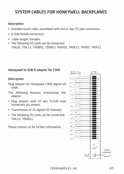
SyStEm caBlES FOR HOnEywEll BacKplanES
Description
• Shielded round cable, assembled with one or two 37 pole connectors.
• D-SUB female connectors.
• Cable length: Variable.• The following I/O cards can be connected: TDIL01, TDIL11, TDOB01, TDOB11 TAOX01, TAOX11, TAIX01, TAIX11
System cables for Honeywell Backplanes
Fasten connector
Description
Plug adapter for Honeywell C300 digital I/O cards.
The following features characterize this adapter:
• Plug adapter with 37 pos. D-SUB male connectors (as shown).
• Transmission of 16 digital I/O channels.
• The following I/O cards can be connected: TDIL11, TDOB11.
Please contact us for further information.
Honeywell to SUB D adaptor for c300
CO
MM
UN
ICA
TIO
N F
OU
ND
AT
ION
Tx-
+
-
Tx+
-
+
-
12
11
14
13C
OM
MU
NIC
AT
ION
FO
UN
DA
TIO
N
mA+
-
mA
+
12
11
14
13 CO
MM
UN
ICA
TIO
N F
OU
ND
AT
ION
mA+
-
mA
+
44
43
42
41
44
43
42
41
54
53
52
51
48 7900 HWM101-UK
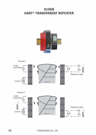
Channel 2
Channel 1
2-wire transmitter
Current
Current
2-wire transmitter
9106B HaRt® tRanSpaREnt REpEatER
9106B aI I.S. isolation barrier - wiring connections
Passive 2-wire
Passive 2-wire
12
11
14
13
CO
MM
UN
ICA
TIO
N F
OU
ND
AT
ION
+
-
44
43
42
41
44
43
42
41
12
11
14
13 CO
MM
UN
ICA
TIO
N F
OU
ND
AT
ION
+
-
54
53
52
51
7900HWM101-UK 49
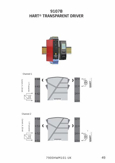
Channel 2
Channel 1
I / P converter
Current, 4...2
0 m
A
I / P converter
Current, 4...2
0 m
A
9107B HaRt® tRanSpaREnt DRIvER
9107B aO I.S. isolation barrier - wiring connections
-
+
-
+
mA
mA
44
43
42
41
44
43
42
41
14
13
12
11
+
- +
mA
mA44
43
42
41
54
53
52
51
14
13
12
11
+
- +
50 7900 HWM101-UK
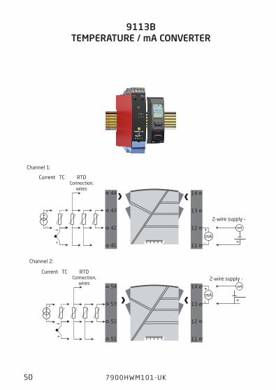
9113B tEmpERatURE / ma cOnvERtER
RTD Connection,
wires
Current TC
Channel 1:
Channel 2:
RTD Connection,
wires
Current TC
9113B aI I.S. isolation barrier - wiring connections
2-wire supply -
2-wire supply -
*
44
43
42
41
44
43
42
41
12
11
14
13
mA
mA+
- +
7900HWM101-UK 51
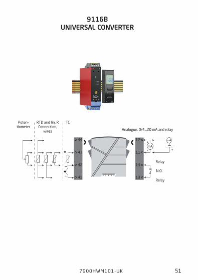
9116B UnIvERSal cOnvERtER
9116B aI I.S. isolation barrier - wiring connections
Poten- tiometer
TCRTD and lin. RConnection,
wires Analogue, 0/4...20 mA and relay
Relay
Relay
N.O.
NAMUR
44
43
42
41
NAMUR
54
53
52
51
Rp
Rs
Rp
Rp
Rs
Rp
+
-
+
-
Rp = 15 kΩ Rs = 750 Ω
Rp = 15 kΩ Rs = 750 Ω
Opto -
Opto +
Opto +14
13
12
11
Opto -
14
13
12
11
52 7900 HWM101-UK
Mechanical switch
Channel 1:
Channel 2:
Mechanical switch
9202B pUlSE ISOlatOR
9202B aO I.S. isolation barrier - wiring connections
Relay
Relay
Channel 1: N.O. or
N.C.
Relay
Relay
Channel 2: N.O. or
N.C.
54
53
52
51
44
43
42
41
V+ V+
V+ V+
14
13
12
11
14
13
12
11
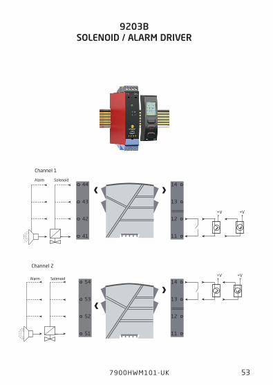
7900HWM101-UK 53
Channel 2
SolenoidAlarm
Channel 1
SolenoidAlarm
9203B SOlEnOID / alaRm DRIvER
9203B aI I.S. isolation barrier - wiring connections
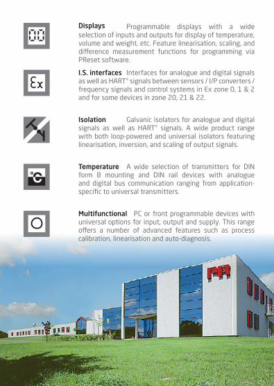
Programmable displays with a wide selection of inputs and outputs for display of temperature, volume and weight, etc. Feature linearisation, scaling, and difference measurement functions for programming via PReset software.
Displays
A wide selection of transmitters for DIN form B mounting and DIN rail devices with analogue and digital bus communication ranging from application- specific to universal transmitters.
temperature
Galvanic isolators for analogue and digital signals as well as HART® signals. A wide product range with both loop-powered and universal isolators featuring linearisation, inversion, and scaling of output signals.
Isolation
Interfaces for analogue and digital signals as well as HART® signals between sensors / I/P converters / frequency signals and control systems in Ex zone 0, 1 & 2 and for some devices in zone 20, 21 & 22.
I.S. interfaces
PC or front programmable devices with universal options for input, output and supply. This range offers a number of advanced features such as process calibration, linearisation and auto-diagnosis.
multifunctional

Head officeDenmark www.prelectronics.comPR electronics A/S [email protected] 10 tel. +45 86 37 26 77DK-8410 Rønde fax +45 86 37 30 85
www.prelectronics.fr [email protected]
www.prelectronics.de [email protected]
www.prelectronics.es [email protected]
www.prelectronics.it [email protected]
www.prelectronics.se [email protected]
www.prelectronics.co.uk [email protected]
www.prelectronics.com [email protected]
www.prelectronics.cn [email protected]
Recommended