Proprietary Notice: The information contained herein is the confidential property of GE Oil & Gas and its affiliates; it is to be used only for the benefit of GE Oil & Gas and shall not be reproduced or used for any purpose without the written consent of GE Oil & Gas.
EQUIPMENT OVERVIEW SHEET
Shallow Water Production System
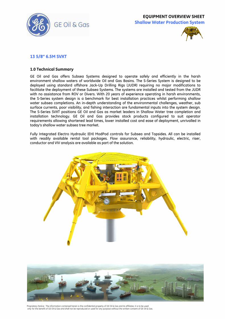
13 5/8” 6.5M SVXT
1.0 Technical Summary
GE Oil and Gas offers Subsea Systems designed to operate safely and efficiently in the harsh environment shallow waters of worldwide Oil and Gas Basins. The S-Series System is designed to be deployed using standard offshore Jack-Up Drilling Rigs (JUDR) requiring no major modifications to facilitate the deployment of these Subsea Systems. The systems are installed and tested from the JUDR with no assistance from ROV or Divers. With 20 years of experience operating in harsh environments, the S-Series system design is a benchmark for best installation practices whilst performing shallow water subsea completions. An in-depth understanding of the environmental challenges, weather, sub surface currents, poor visibility, and fishing interaction are fundamental inputs into the system design. The S-Series SVXT positions GE Oil and Gas as market leaders in Shallow Water tree completion and installation technology. GE Oil and Gas provides stock products configured to suit operator requirements allowing shortened lead times, lower installed cost and ease of deployment, unrivalled in today’s shallow water subsea tree market. Fully Integrated Electro Hydraulic (EH) ModPod controls for Subsea and Topsides. All can be installed with readily available rental tool packages. Flow assurance, reliability, hydraulic, electric, riser, conductor and VIV analysis are available as part of the solution.
Proprietary Notice: The information contained herein is the confidential property of GE Oil & Gas and its affiliates; it is to be used only for the benefit of GE Oil & Gas and shall not be reproduced or used for any purpose without the written consent of GE Oil & Gas.
EQUIPMENT OVERVIEW SHEET Shallow Water Production System
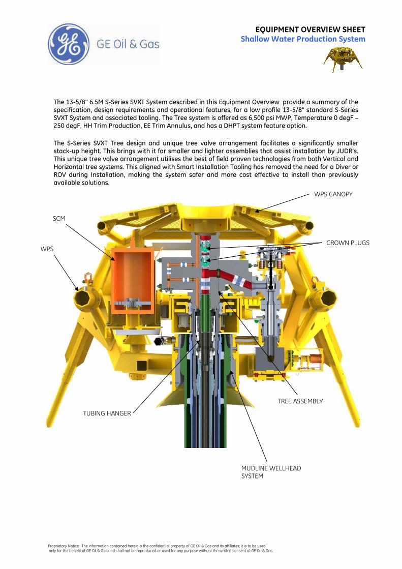
The 13-5/8" 6.5M S-Series SVXT System described in this Equipment Overview provide a summary of the specification, design requirements and operational features, for a low profile 13-5/8" standard S-Series SVXT System and associated tooling. The Tree system is offered as 6,500 psi MWP, Temperature 0 degF – 250 degF, HH Trim Production, EE Trim Annulus, and has a DHPT system feature option.
The S-Series SVXT Tree design and unique tree valve arrangement facilitates a significantly smaller stack-up height. This brings with it far smaller and lighter assemblies that assist installation by JUDR’s. This unique tree valve arrangement utilises the best of field proven technologies from both Vertical and Horizontal tree systems. This aligned with Smart Installation Tooling has removed the need for a Diver or ROV during Installation, making the system safer and more cost effective to install than previously available solutions.
WPS CANOPY
MUDLINE WELLHEAD SYSTEM
TUBING HANGER
CROWN PLUGS
TREE ASSEMBLY
WPS
SCM
Proprietary Notice: The information contained herein is the confidential property of GE Oil & Gas and its affiliates; it is to be used only for the benefit of GE Oil & Gas and shall not be reproduced or used for any purpose without the written consent of GE Oil & Gas.
EQUIPMENT OVERVIEW SHEET Shallow Water Production System
Key Features:
The S-Series SVXT system offered has the following key features compared to existing GE Oil & Gas 13 5/8” Conventional Tree’s.
• Reduced envelope sizes of Tree and WPS saving approximately 20% overall weight in system. Aided by introducing compact actuators which are 34% lighter than previous designs.
• Removal of Lower Master (Manual) and Swab (Hydraulic) valves in production bore, replacing these with crown plugs to give unique barrier philosophy that removes the need for a separate Tree Cap.
• Removal of Hydraulic Tree Cap thus saving equipment and installation time.
• Installation Operations performed via Workover Control System (WOCS) stab plate on the Tree Running Tool (TRT) removing the requirement for an ROV or Diver to remove traditionally made up Junction Plates.
• Use of smart tooling to install the Production Control Bridging Plate whilst running the Corrosion Cap. This activity was traditionally achieved by intervention by Diver or ROV.
• Tree Running Tool contains a shear valve allowing the 7 5/8” landing string to be used as
lubricator string, providing a well control barrier during wireline activities.
• Xmas Tree is provided with GE Oil & Gas fully integrated ModPod Control System minimizing the requirements for third party interfaces.
• ‘Rental’ Smart Tooling packages allow safe and efficient installation of subsea equipment in harsh shallow water environments.
Tubing Hanger
Proprietary Notice: The information contained herein is the confidential property of GE Oil & Gas and its affiliates; it is to be used only for the benefit of GE Oil & Gas and shall not be reproduced or used for any purpose without the written consent of GE Oil & Gas.
EQUIPMENT OVERVIEW SHEET Shallow Water Production System
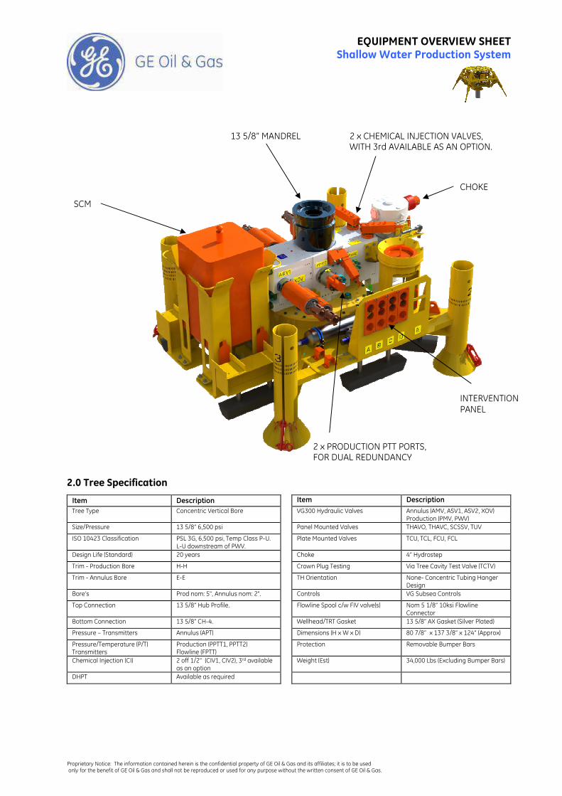
2.0 Tree Specification
Item Description Item Description
Tree Type Concentric Vertical Bore VG300 Hydraulic Valves Annulus (AMV, ASV1, ASV2, XOV) Production (PMV, PWV)
Size/Pressure 13 5/8” 6,500 psi Panel Mounted Valves THAVO, THAVC, SCSSV, TUV
ISO 10423 Classification PSL 3G, 6,500 psi, Temp Class P-U. L-U downstream of PWV.
Plate Mounted Valves TCU, TCL, FCU, FCL
Design Life (Standard) 20 years Choke 4” Hydrostep
Trim - Production Bore H-H Crown Plug Testing Via Tree Cavity Test Valve (TCTV)
Trim - Annulus Bore E-E TH Orientation None- Concentric Tubing Hanger Design
Bore’s Prod nom: 5", Annulus nom: 2". Controls VG Subsea Controls
Top Connection 13 5/8” Hub Profile. Flowline Spool c/w FIV valve(s) Nom 5 1/8” 10ksi Flowline Connector
Bottom Connection 13 5/8” CH-4. Wellhead/TRT Gasket 13 5/8” AX Gasket (Silver Plated)
Pressure – Transmitters Annulus (APT) Dimensions (H x W x D) 80 7/8” x 137 3/8” x 124” (Approx)
Pressure/Temperature (P/T) Transmitters
Production (PPTT1, PPTT2) Flowline (FPTT)
Protection Removable Bumper Bars
Chemical Injection (CI) 2 off 1/2” (CIV1, CIV2), 3rd available as an option
Weight (Est) 34,000 Lbs (Excluding Bumper Bars)
DHPT Available as required
SCM
INTERVENTION PANEL
CHOKE
2 x PRODUCTION PTT PORTS, FOR DUAL REDUNDANCY
13 5/8” MANDREL 2 x CHEMICAL INJECTION VALVES, WITH 3rd AVAILABLE AS AN OPTION.
Proprietary Notice: The information contained herein is the confidential property of GE Oil & Gas and its affiliates; it is to be used only for the benefit of GE Oil & Gas and shall not be reproduced or used for any purpose without the written consent of GE Oil & Gas.
EQUIPMENT OVERVIEW SHEET Shallow Water Production System
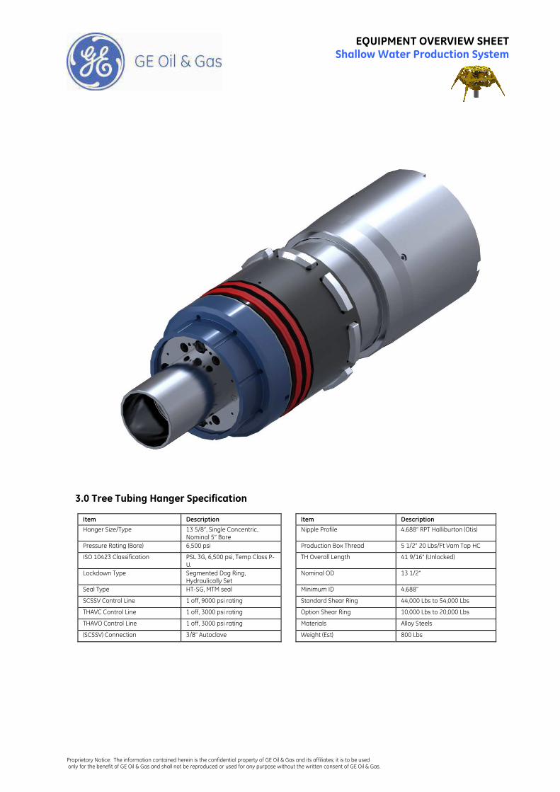
3.0 Tree Tubing Hanger Specification
Item Description Item Description
Hanger Size/Type 13 5/8”, Single Concentric, Nominal 5” Bore
Nipple Profile 4.688” RPT Halliburton (Otis)
Pressure Rating (Bore) 6,500 psi Production Box Thread 5 1/2” 20 Lbs/Ft Vam Top HC
ISO 10423 Classification PSL 3G, 6,500 psi, Temp Class P-U.
TH Overall Length 41 9/16” (Unlocked)
Lockdown Type Segmented Dog Ring, Hydraulically Set
Nominal OD 13 1/2”
Seal Type HT-SG, MTM seal Minimum ID 4.688”
SCSSV Control Line 1 off, 9000 psi rating Standard Shear Ring 44,000 Lbs to 54,000 Lbs
THAVC Control Line 1 off, 3000 psi rating Option Shear Ring 10,000 Lbs to 20,000 Lbs
THAVO Control Line 1 off, 3000 psi rating Materials Alloy Steels
(SCSSV) Connection 3/8” Autoclave Weight (Est) 800 Lbs
Proprietary Notice: The information contained herein is the confidential property of GE Oil & Gas and its affiliates; it is to be used only for the benefit of GE Oil & Gas and shall not be reproduced or used for any purpose without the written consent of GE Oil & Gas.
EQUIPMENT OVERVIEW SHEET Shallow Water Production System
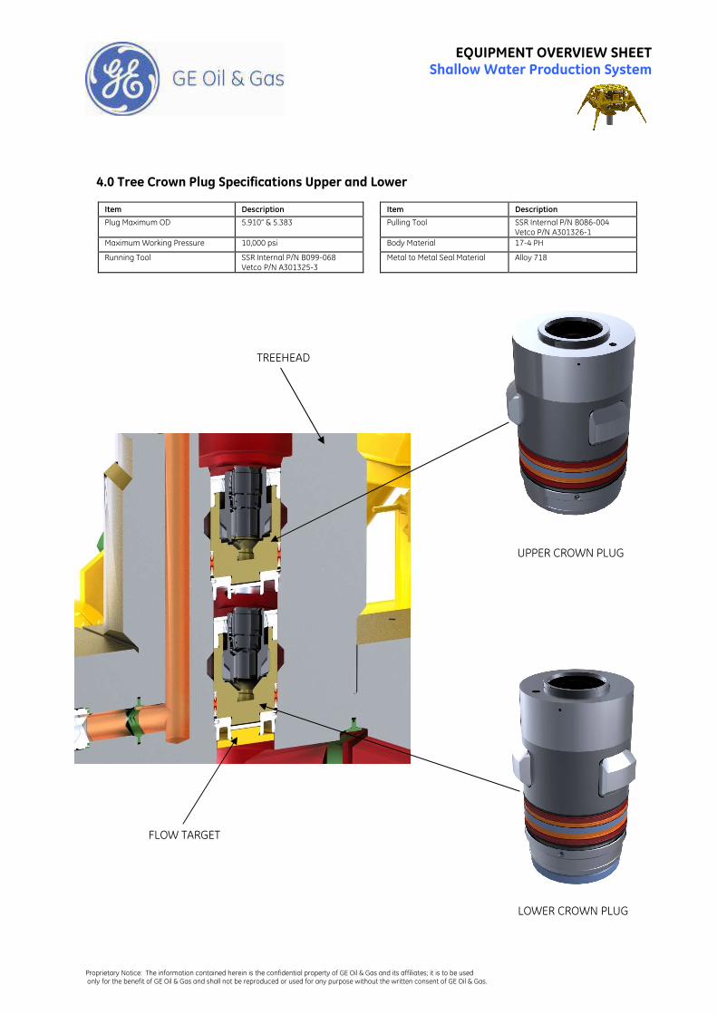
4.0 Tree Crown Plug Specifications Upper and Lower
Item Description Item Description
Plug Maximum OD 5.910” & 5.383 Pulling Tool SSR Internal P/N B086-004 Vetco P/N A301326-1
Maximum Working Pressure 10,000 psi Body Material 17-4 PH
Running Tool SSR Internal P/N B099-068 Vetco P/N A301325-3
Metal to Metal Seal Material
Alloy 718
LOWER CROWN PLUG
UPPER CROWN PLUG
TREEHEAD
FLOW TARGET
Proprietary Notice: The information contained herein is the confidential property of GE Oil & Gas and its affiliates; it is to be used only for the benefit of GE Oil & Gas and shall not be reproduced or used for any purpose without the written consent of GE Oil & Gas.
EQUIPMENT OVERVIEW SHEET Shallow Water Production System
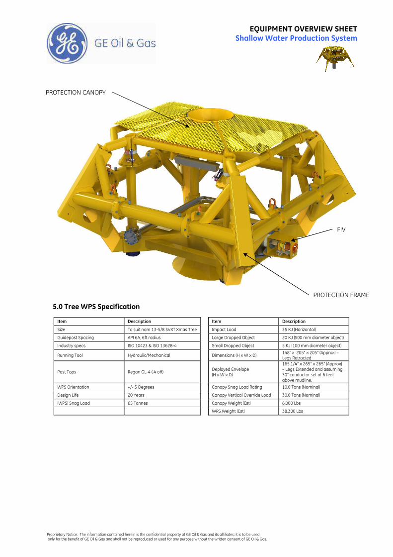
5.0 Tree WPS Specification
Item Description Item Description
Size To suit nom 13-5/8 SVXT Xmas Tree Impact Load 35 KJ (Horizontal)
Guidepost Spacing API 6A, 6ft radius Large Dropped Object 20 KJ (500 mm diameter object)
Industry specs ISO 10423 & ISO 13628-4 Small Dropped Object 5 KJ (100 mm diameter object)
Running Tool Hydraulic/Mechanical
Dimensions (H x W x D) 148” x 205” x 205” (Approx) – Legs Retracted
Post Tops Regan GL-4 ( 4 off)
Deployed Envelope (H x W x D)
165 1/4” x 265” x 265” (Approx) – Legs Extended and assuming 30” conductor set at 6 feet above mudline.
WPS Orientation +/- 5 Degrees Canopy Snag Load Rating 10.0 Tons (Nominal)
Design Life 20 Years Canopy Vertical Override Load 30.0 Tons (Nominal)
(WPS) Snag Load 65 Tonnes Canopy Weight (Est) 6,000 Lbs
WPS Weight (Est) 38,300 Lbs
PROTECTION FRAME
PROTECTION CANOPY
FIV
Proprietary Notice: The information contained herein is the confidential property of GE Oil & Gas and its affiliates; it is to be used only for the benefit of GE Oil & Gas and shall not be reproduced or used for any purpose without the written consent of GE Oil & Gas.
EQUIPMENT OVERVIEW SHEET Shallow Water Production System
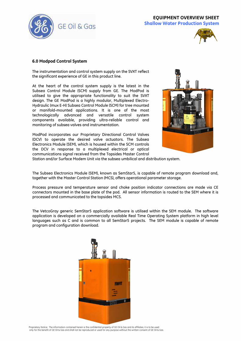
6.0 Modpod Control System
The instrumentation and control system supply on the SVXT reflect the significant experience of GE in this product line.
At the heart of the control system supply is the latest in the
Subsea Control Module (SCM) supply from GE. The ModPod is
utilised to give the appropriate functionality to suit the SVXT
design. The GE ModPod is a highly modular, Multiplexed Electro-
Hydraulic (mux E-H) Subsea Control Module (SCM) for tree mounted
or manifold-mounted applications. It is one of the most
technologically advanced and versatile control system
components available, providing ultra-reliable control and
monitoring of subsea valves and instrumentation.
ModPod incorporates our Proprietary Directional Control Valves
(DCV) to operate the desired valve actuators. The Subsea
Electronics Module (SEM), which is housed within the SCM controls
the DCV in response to a multiplexed electrical or optical
communications signal received from the Topsides Master Control
Station and/or Surface Modem Unit via the subsea umbilical and distribution system.
The Subsea Electronics Module (SEM), known as SemStar5, is capable of remote program download and, together with the Master Control Station (MCS), offers operational parameter storage. Process pressure and temperature sensor and choke position indicator connections are made via CE connectors mounted in the base plate of the pod. All sensor information is routed to the SEM where it is processed and communicated to the topsides MCS. The VetcoGray generic SemStar5 application software is utilised within the SEM module. The software application is developed on a commercially available Real Time Operating System platform in high level languages such as C and is common to all SemStar5 projects. The SEM module is capable of remote program and configuration download.
Proprietary Notice: The information contained herein is the confidential property of GE Oil & Gas and its affiliates; it is to be used only for the benefit of GE Oil & Gas and shall not be reproduced or used for any purpose without the written consent of GE Oil & Gas.
EQUIPMENT OVERVIEW SHEET Shallow Water Production System
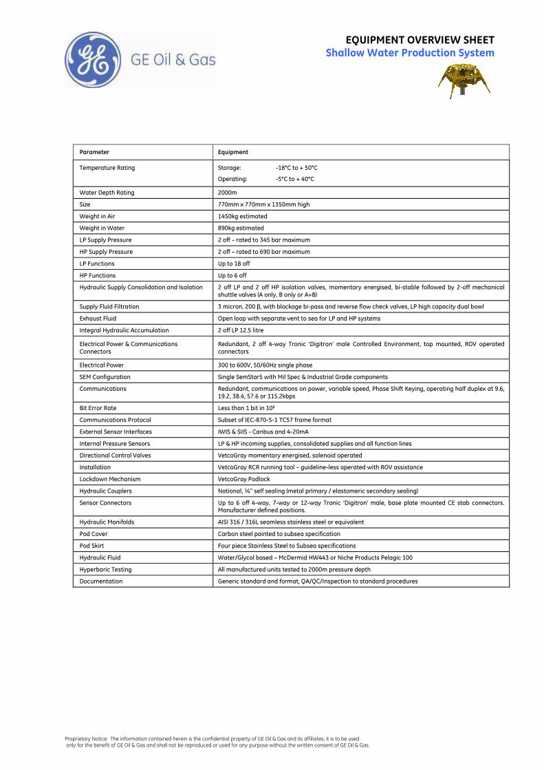
Parameter Equipment
Temperature Rating Storage: -18°C to + 50°C
Operating: -5°C to + 40°C
Water Depth Rating 2000m
Size 770mm x 770mm x 1350mm high
Weight in Air 1450kg estimated
Weight in Water 890kg estimated
LP Supply Pressure 2 off – rated to 345 bar maximum
HP Supply Pressure 2 off – rated to 690 bar maximum
LP Functions Up to 18 off
HP Functions Up to 6 off
Hydraulic Supply Consolidation and Isolation 2 off LP and 2 off HP isolation valves, momentary energised, bi-stable followed by 2-off mechanical shuttle valves (A only, B only or A+B)
Supply Fluid Filtration 3 micron, 200 β, with blockage bi-pass and reverse flow check valves, LP high capacity dual bowl
Exhaust Fluid Open loop with separate vent to sea for LP and HP systems
Integral Hydraulic Accumulation 2 off LP 12.5 litre
Electrical Power & Communications Connectors
Redundant, 2 off 4-way Tronic ‘Digitron’ male Controlled Environment, top mounted, ROV operated connectors
Electrical Power 300 to 600V, 50/60Hz single phase
SEM Configuration Single SemStar5 with Mil Spec & Industrial Grade components
Communications Redundant, communications on power, variable speed, Phase Shift Keying, operating half duplex at 9.6, 19.2, 38.4, 57.6 or 115.2kbps
Bit Error Rate Less than 1 bit in 106
Communications Protocol Subset of IEC-870-5-1 TC57 frame format
External Sensor Interfaces IWIS & SIIS - Canbus and 4-20mA
Internal Pressure Sensors LP & HP incoming supplies, consolidated supplies and all function lines
Directional Control Valves VetcoGray momentary energised, solenoid operated
Installation VetcoGray RCR running tool – guideline-less operated with ROV assistance
Lockdown Mechanism VetcoGray Podlock
Hydraulic Couplers National, ¼” self sealing (metal primary / elastomeric secondary sealing)
Sensor Connectors Up to 6 off 4-way, 7-way or 12-way Tronic ‘Digitron’ male, base plate mounted CE stab connectors. Manufacturer defined positions.
Hydraulic Manifolds AISI 316 / 316L seamless stainless steel or equivalent
Pod Cover Carbon steel painted to subsea specification
Pod Skirt Four piece Stainless Steel to Subsea specifications
Hydraulic Fluid Water/Glycol based – McDermid HW443 or Niche Products Pelagic 100
Hyperbaric Testing All manufactured units tested to 2000m pressure depth
Documentation Generic standard and format, QA/QC/Inspection to standard procedures
Proprietary Notice: The information contained herein is the confidential property of GE Oil & Gas and its affiliates; it is to be used only for the benefit of GE Oil & Gas and shall not be reproduced or used for any purpose without the written consent of GE Oil & Gas.
EQUIPMENT OVERVIEW SHEET Shallow Water Production System
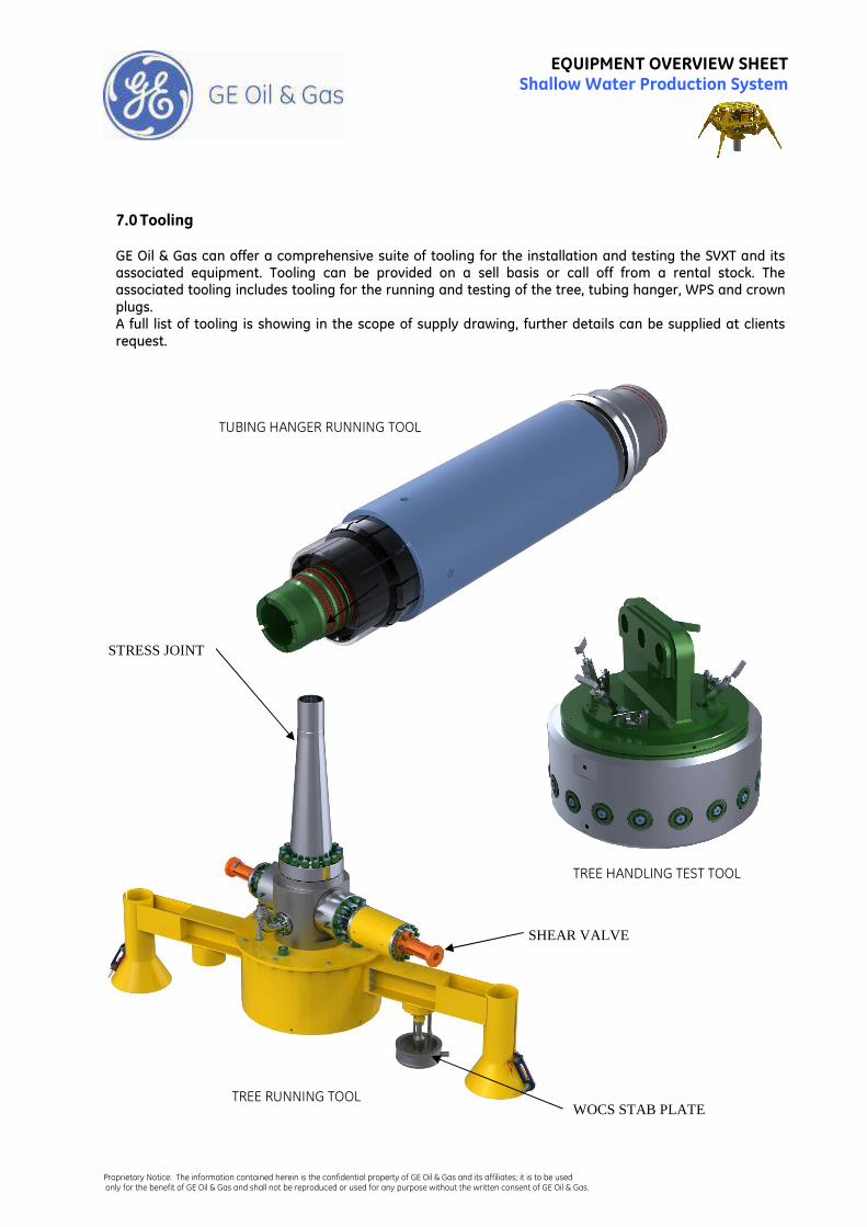
7.0 Tooling GE Oil & Gas can offer a comprehensive suite of tooling for the installation and testing the SVXT and its associated equipment. Tooling can be provided on a sell basis or call off from a rental stock. The associated tooling includes tooling for the running and testing of the tree, tubing hanger, WPS and crown plugs. A full list of tooling is showing in the scope of supply drawing, further details can be supplied at clients request.
TUBING HANGER RUNNING TOOL
TREE HANDLING TEST TOOL
TREE RUNNING TOOL WOCS STAB PLATE
SHEAR VALVE
STRESS JOINT
Proprietary Notice: The information contained herein is the confidential property of GE Oil & Gas and its affiliates; it is to be used only for the benefit of GE Oil & Gas and shall not be reproduced or used for any purpose without the written consent of GE Oil & Gas.
EQUIPMENT OVERVIEW SHEET Shallow Water Production System
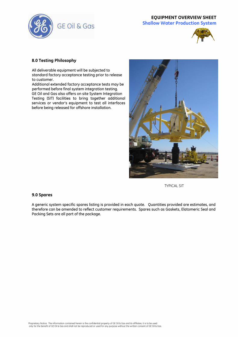
8.0 Testing Philosophy All deliverable equipment will be subjected to standard factory acceptance testing prior to release to customer. Additional extended factory acceptance tests may be performed before final system integration testing. GE Oil and Gas also offers on site System Integration Testing (SIT) facilities to bring together additional services or vendor’s equipment to test all interfaces before being released for offshore installation.
9.0 Spares A generic system specific spares listing is provided in each quote. Quantities provided are estimates, and therefore can be amended to reflect customer requirements. Spares such as Gaskets, Elatomeric Seal and Packing Sets are all part of the package.
TYPICAL SIT
Recommended