1
SVR-1-KW1
Simplex Repeater Maker for Kenwood Two-Way Radios
Manual Revision: 2018-03-20 Rev D
Covers Software Revisions: VS-1XXX: 01.62.00 & Higher
Covers Hardware Revisions: VS-KW1: 7508D
This manual & product supports the following Kenwood two-way radios: Portables: TK-2180, TK-3180 Mobiles: TK-7180, TK-8180
2
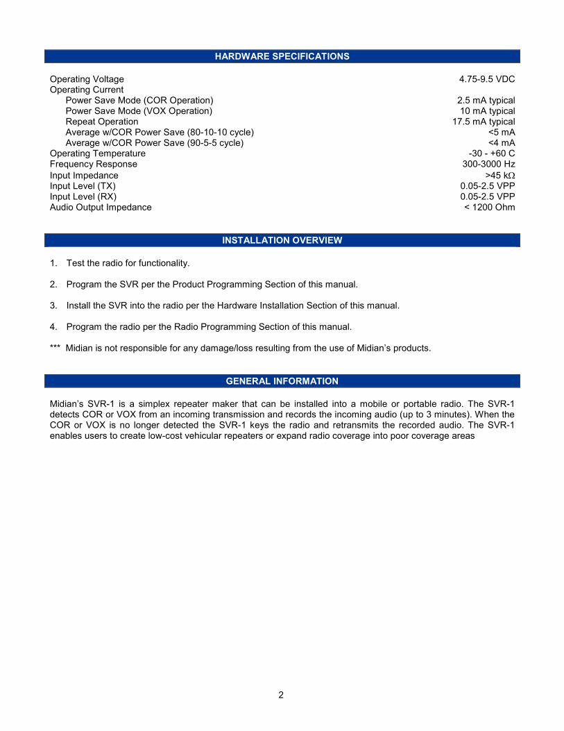
HARDWARE SPECIFICATIONS
Operating Voltage 4.75-9.5 VDC Operating Current Power Save Mode (COR Operation) 2.5 mA typical Power Save Mode (VOX Operation) 10 mA typical Repeat Operation 17.5 mA typical Average w/COR Power Save (80-10-10 cycle) <5 mA Average w/COR Power Save (90-5-5 cycle) <4 mA Operating Temperature -30 - +60 C Frequency Response 300-3000 Hz
Input Impedance >45 kΩ Input Level (TX) 0.05-2.5 VPP Input Level (RX) 0.05-2.5 VPP Audio Output Impedance < 1200 Ohm
INSTALLATION OVERVIEW
1. Test the radio for functionality. 2. Program the SVR per the Product Programming Section of this manual. 3. Install the SVR into the radio per the Hardware Installation Section of this manual. 4. Program the radio per the Radio Programming Section of this manual. *** Midian is not responsible for any damage/loss resulting from the use of Midian’s products.
GENERAL INFORMATION
Midian’s SVR-1 is a simplex repeater maker that can be installed into a mobile or portable radio. The SVR-1 detects COR or VOX from an incoming transmission and records the incoming audio (up to 3 minutes). When the COR or VOX is no longer detected the SVR-1 keys the radio and retransmits the recorded audio. The SVR-1 enables users to create low-cost vehicular repeaters or expand radio coverage into poor coverage areas
3
1BPRODUCT PROGRAMMING
The SVR series are programmed using Midian’s KL-4F and the MPS software. Please reference the KL-4 manual for setup instructions of the KL-4 hardware.
KL4-F USB PORT ASSIGNMENT and SOFTWARE INSTALLATION Go to our website midians.com and under downloads> software download the latest MPS software version. If using the supplied CD-ROM insert it into the PC’s CD-ROM drive. In the browser that will pop-up, install the MPS programming software. Be certain that the “Install KL-4 USB Driver” box is checked during the installation process. Open Windows’ Control Panel and go to Device Manager. Open Ports (COM& LPT) to identify the port assignment issued by computer. Plug in the KL4 programmer to the USB port and the screen will flash and show the device location. Open the software and choose product from product tree then set appropriate comport selection in the MPS software as needed, from the product selection screen on the programming software select the appropriate product from the list and click OK. Set the parameters of the SVR-1-KW1 software to fit the application. If any clarifications on a feature are required, move the mouse cursor over the feature name until the question mark appears and right click, a definition of the feature will be shown. After entering the parameters, save the file by going to File - Save As. Enter the file name in the File Name block and click Save. Saving the file will allow for quick and easy reprogramming of units. After the latest MPS has been installed default programming files for specific radio models can be found at: C:\Apps\Midian\MPS\MPS_vX_xx\Additional Default Files\ SVR\Kenwood Programming: Plug the board onto the KL-4F P-6 connector. Push and hold the power button on the KL-4F and wait for three seconds, still holding the power button click “Program Unit” in the MPS software. Reading: Plug the board onto the KL-4F. Push and hold the power button on the KL-4F and wait for three seconds, still holding the power button click “Read Unit” in the MPS software.
4
AUDIO LEVELS ALIGNMENT
This section describes how to determine and set the audio levels. Audio Levels Overview:
To ensure the best audio quality, the SVR must be configured to match the audio levels used by the radio. The SVR uses programmable gain amplifiers to accomplish this. Determining the gain settings for these amplifiers is an involved process, so Midian simplified this process by developing an algorithm that requires the technician to make only four voltage measurements. From these four measurements, all of the many internal settings are determined. Still, getting the best audio quality will likely require a bit of trial and error. The SVR only has control of audio voltage levels, not input and output impedances. These impedances can dramatically influence the levels. The Four Voltage Measurements:
An oscilloscope and a communications test set/service monitor are required for the measurements. It is recommended that the measurements be recorded in units of mV peak-to-peak. Each measurement must be taken with system modulation at either 60% or 100%, but Midian recommends using 60% A method for controlling transmit modulation is required for accurate measurements in the TX mode. A small speaker held in place near the microphone by a rubber band can serve this purpose in most cases. Use a sine-wave generator to inject a 1000 Hz tone into the speaker. Adjust the output of the sine wave generator so that the transmitter produces 60% of rated modulation while PTT is pressed. Note that if the audio source (such as a speaker) is moved even slightly, the TX modulation may change significantly. Care must be taken to avoid changing the TX modulation while taking the measurements. The first two measurements must be taken using a radio that has not been modified. The 2
nd two measurements
require that the SVR is installed and power is applied to the radio/SVR. These measurements must be taken within 15 seconds of powering the SVR on. This is because the SVR may enter power saving mode after that time. Measurements made while the SVR is in power saving mode will not be valid. The unit ships with the power save feature enabled by default. The power save feature can be disabled via the KL-3 programming software so that it will not interfere with taking measurements, if desired. Please note that the levels provided to the option board are different between narrow band and wide band. 1. RX Output: The goal of this procedure is to determine the audio level that would normally appear at the RX
audio insertion point in an unmodified radio. With a fully quieting signal modulated with a 1000 Hz tone at 60%. Measure the voltage level appearing at the junction of R-670 and IC-607 Pin 28 on the TK-2180 & TK-3180 or at the junction of C-591 and IC-413 Pin 4 for the TK-7180 & TK-8180.
2. TX Output: The goal of this procedure is to determine the audio level that would normally appear at the TX
audio insertion point in an unmodified radio. Provide the radio an audio source generating a 1000 Hz tone and key the radio. Adjust the audio source such that the modulation is at 60%. Measure the voltage level appearing at the junction of R-659 and R-660 on the TK-2180 & TK-3180 or at the junction of C-485 and IC-413 Pin 14 for the TK-7180 & TK-8180.
3. RX Input: The goal of this procedure is to determine the audio level that the SVR board will see at the RX
audio pickup point after it is installed. The SVR must be installed and powered-on while making this measurement. Modulate a 1000 Hz tone at 60%. Measure the audio level at the junction of P1-22 and C-42 on the SVR.
4. TX Input: The goal of this procedure is to determine the audio level that the SVR board will see at the TX audio pickup point after it is installed. The SVR must be installed and powered-on while making this measurement. Provide the radio the same audio source and level as in Step 2, generating a 1000 Hz tone and key the radio. Measure the audio level at the junction of P1-21 and C-3 on the SVR.
5
Programming the Audio Levels:
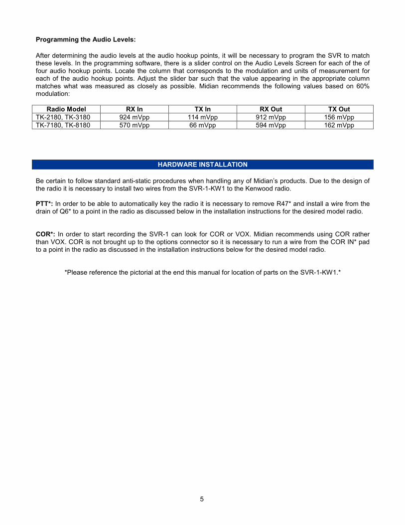
After determining the audio levels at the audio hookup points, it will be necessary to program the SVR to match these levels. In the programming software, there is a slider control on the Audio Levels Screen for each of the of four audio hookup points. Locate the column that corresponds to the modulation and units of measurement for each of the audio hookup points. Adjust the slider bar such that the value appearing in the appropriate column matches what was measured as closely as possible. Midian recommends the following values based on 60% modulation:
Radio Model RX In TX In RX Out TX Out
TK-2180, TK-3180 924 mVpp 114 mVpp 912 mVpp 156 mVpp
TK-7180, TK-8180 570 mVpp 66 mVpp 594 mVpp 162 mVpp
HARDWARE INSTALLATION
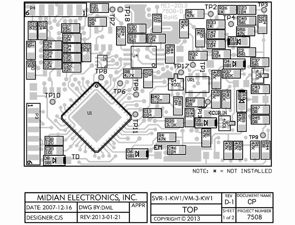
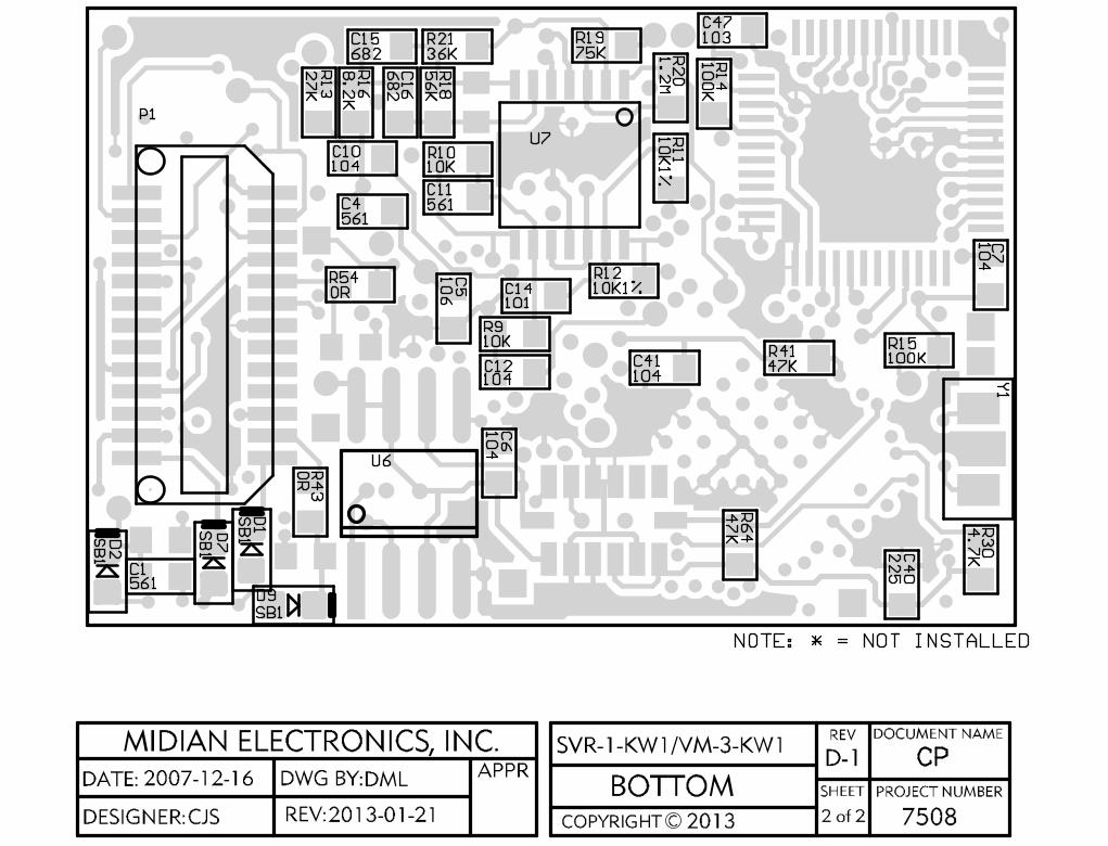
Be certain to follow standard anti-static procedures when handling any of Midian’s products. Due to the design of the radio it is necessary to install two wires from the SVR-1-KW1 to the Kenwood radio. PTT*: In order to be able to automatically key the radio it is necessary to remove R47* and install a wire from the drain of Q6* to a point in the radio as discussed below in the installation instructions for the desired model radio. COR*: In order to start recording the SVR-1 can look for COR or VOX. Midian recommends using COR rather than VOX. COR is not brought up to the options connector so it is necessary to run a wire from the COR IN* pad to a point in the radio as discussed in the installation instructions below for the desired model radio.
*Please reference the pictorial at the end this manual for location of parts on the SVR-1-KW1.*
6
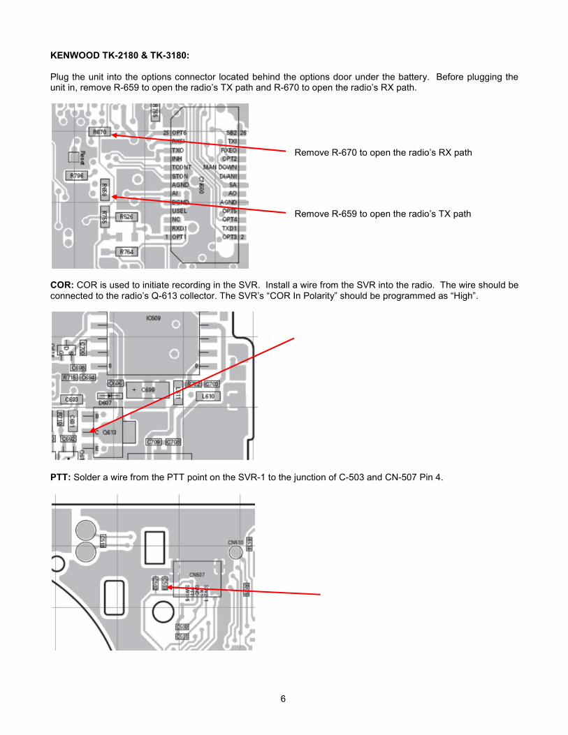
KENWOOD TK-2180 & TK-3180: Plug the unit into the options connector located behind the options door under the battery. Before plugging the unit in, remove R-659 to open the radio’s TX path and R-670 to open the radio’s RX path.
COR: COR is used to initiate recording in the SVR. Install a wire from the SVR into the radio. The wire should be connected to the radio’s Q-613 collector. The SVR’s “COR In Polarity” should be programmed as “High”.
PTT: Solder a wire from the PTT point on the SVR-1 to the junction of C-503 and CN-507 Pin 4.
Remove R-670 to open the radio’s RX path
Remove R-659 to open the radio’s TX path
7
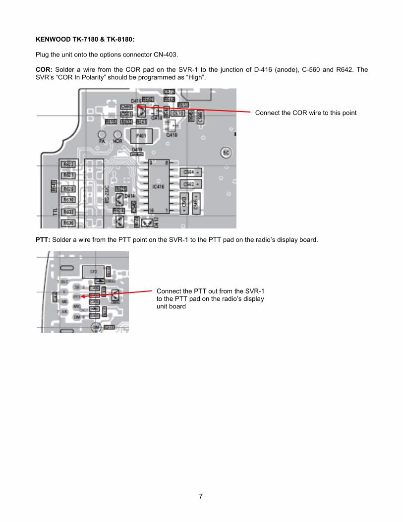
KENWOOD TK-7180 & TK-8180: Plug the unit onto the options connector CN-403. COR: Solder a wire from the COR pad on the SVR-1 to the junction of D-416 (anode), C-560 and R642. The SVR’s “COR In Polarity” should be programmed as “High”.
PTT: Solder a wire from the PTT point on the SVR-1 to the PTT pad on the radio’s display board.
Connect the PTT out from the SVR-1 to the PTT pad on the radio’s display unit board
Connect the COR wire to this point
8
RADIO PROGRAMMING
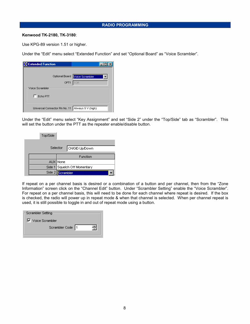
Kenwood TK-2180, TK-3180: Use KPG-89 version 1.51 or higher. Under the “Edit” menu select “Extended Function” and set “Optional Board” as “Voice Scrambler”.
Under the “Edit” menu select “Key Assignment” and set “Side 2” under the “Top/Side” tab as “Scrambler”. This will set the button under the PTT as the repeater enable/disable button.
If repeat on a per channel basis is desired or a combination of a button and per channel, then from the “Zone Information” screen click on the “Channel Edit” button. Under “Scrambler Setting” enable the “Voice Scrambler”. For repeat on a per channel basis, this will need to be done for each channel where repeat is desired. If the box is checked, the radio will power up in repeat mode & when that channel is selected. When per channel repeat is used, it is still possible to toggle in and out of repeat mode using a button.
9
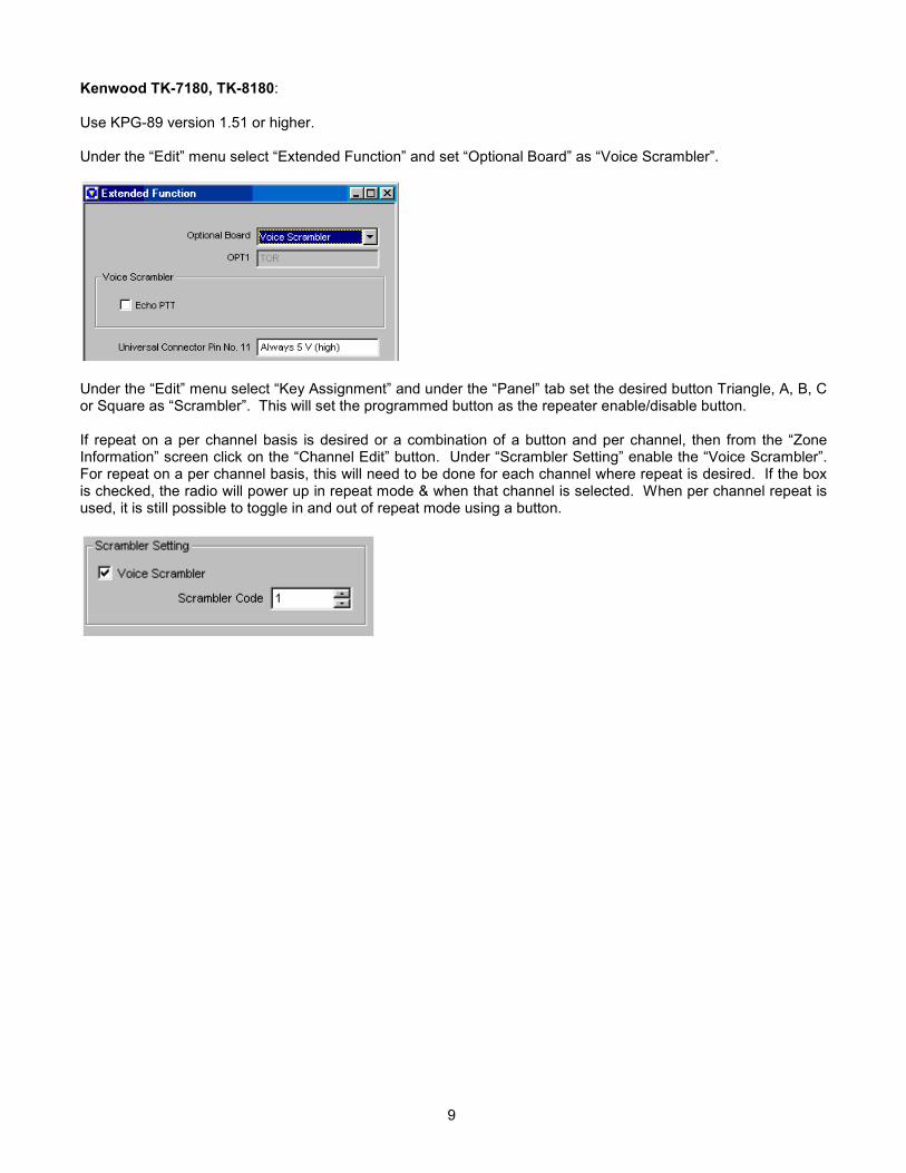
Kenwood TK-7180, TK-8180: Use KPG-89 version 1.51 or higher. Under the “Edit” menu select “Extended Function” and set “Optional Board” as “Voice Scrambler”.
Under the “Edit” menu select “Key Assignment” and under the “Panel” tab set the desired button Triangle, A, B, C or Square as “Scrambler”. This will set the programmed button as the repeater enable/disable button. If repeat on a per channel basis is desired or a combination of a button and per channel, then from the “Zone Information” screen click on the “Channel Edit” button. Under “Scrambler Setting” enable the “Voice Scrambler”. For repeat on a per channel basis, this will need to be done for each channel where repeat is desired. If the box is checked, the radio will power up in repeat mode & when that channel is selected. When per channel repeat is used, it is still possible to toggle in and out of repeat mode using a button.

10
OPERATION
SVR Operation:
Repeater Enable/Disable: Press the radio key that was assigned in the radio programming. A tone will be
emitted from the radio and the ◊ symbol will appear on the display of the radio indicating repeat mode. If repeat
on a per channel basis is being used, then switching between an enabled or non-enabled channel causes the ◊ symbol to appear or disappear.
TECHNICAL NOTES
Radio Compatibility: Midian has taken the utmost care to ensure the option board integrates into the radio with minimal impact to the features of the radio. However, some features may not be available in the radio when an option board is used. If a feature is not available, please contact Midian to see if the feature can be added.
MIDIAN CONTACT INFORMATION
MIDIAN ELECTRONICS, INC.
2030 N. Forbes Blvd. #101 Tucson, Arizona 85745 USA
Toll-Free: 1-800-MIDIANS Main: 520-884-7981 E-mail: [email protected]: www.midians.com
1
1
2
2
3
3
4
4
5
5
6
6
D D
C C
B B
A A
1.2MR42
CODE 2P1:25
TP5
TP18
*R53
100KR15
47KR39
0RR44
-
+
2
31U7:1
560pC2
N/CP1:9
TP7
TP17
P4:1
3
1
2
4
5 6
U5
100pC14
P3:
2
KW3 PTT OUTP1:19
560pC11
AUDIO ENAP1:17100p
C39
.1uC30
0RL1
4.7KR30
.1uC48
EMER INPAD1
PROG OUTPAD4
PROG INPAD3
.01uC21
2.2uC20
0RR45
.1uC41
TP4
.1uC34
75KR19
39pC44 TXI
P1:24
COR INPAD2
N/CP1:11
560pC37
1.2MR20
+5VP1:14
.1uC13
.1uC29
47KR41
AUDIO ENHPAD6
2.2uC26
16
13
42
11
9
4
3
37
8
47
28
24
27
20
18
36
43
46
48
45
41
644
1 2 3840 39
34
21
22
7
35
17
19
29
25
23
26
12
10
5
15
14
33323031
49
U1
TP9
MODE INP1:20
.1uC42
.1uC22
P4:6
10uC36
.1uC46
27K
R13
.01uC9
560pC19
*R52
47KR31
560pC4
47KR3
47KR6
NTA4001Q7
8.2KR16
10K1%R11
GNDP1:10
.1uC10
CODE 0P1:1
47KR1
.0068uC15
16
15
33
35
36
37
38
3
11
12
20
46
21
2
39
40
41
42
32 31 13 10 45 1743
30
29
26
27
28
5 14 34 44
1
4
67
8
9
18
19
22
23
24
25
47
48
U3
*R17
CODE 3
P1:8
10KR9
N/CP1:7
1KR32
.1uC12
P4:2
0RR47
560pC43
47KR38
.1uC3
.1uC23
.1uC31
10uC32
.1uC7
.1uC25
10K1%R12
N/CP1:5
N/CP1:12
*R48
CODE 1
P1:2
7 48
2 5
1 6 3
U4
100KR40
0RR54
P3:
5
12pC38
TP11
2.2uC27
P4:3
*R55
P4:4
36KR21
560pC1
56KR18
TXOP1:21
1KR33
1KR26
.1uC28
SIDE TONEP1:15
P4:5
-
+
13
1214
411
U7:4
KW1 PROG INP1:3
P3:
3
N/CP1:16
47KR2
KW3 COR INP1:18
-
+
6
57U7:2
220pC24
.1uC33
100KR14
-
+
9
108U7:3
NTA4001Q6
*C17
.0068uC16
32.768KHzY1
TRUNK DELAYPAD7
RXEOP1:22
P3:
42RR49
2RR50
2RR51
10KR10
TP6
47K
R4
RXEI
P1:23
.001uC18GND
P1:13
47KR7
100KR37
4.7KR8
10uC35
TP13
1KR25
TP8
NTA4001Q4
TP10
VIN+P1:26
P3:
1
TP2
KW1 PTT OUTP1:6
PTT INP1:4
TP1
.01uC45
TP3
0RR43
+VIN
+3.3VDD
+3.3VDD
+3.3VA
+3.3V
VAN
VAN
VAN
VAN
+3.3V
+3.3V
+3.3V
+3.3V +3.3V+3.3V
+3.3V
+3.3V
+3.3VDD
+3.3VA
+3.3V
+3.3V
+3.3V
+3.3V
+3.3V
VAN
+VIN
+3.3V
+3.3V
+3.3V
A_ROUTE
B_ROUTE
(SOURCE)
NOTES:
* = NOT INSTALLED
KW3 PTT IN
KW3 PTT IN
KW3 PROG IN
KW3 PROG IN
A_ROUTE
B_ROUTE
+
10uC5
.01uC47
3.3KR24
3.3KR28
2.2uC40
TRUNKING_DELAY
TRUNKING_DELAY
*R57
560pC49
CS7 SO12 SI13 SCK14
DVDD 1
INT29 INT18
GND 2
*
AVDD 6
GND 5
IADDR0 4
N/C 3
GND 10
GND 11
U10
.1uC6
+3.3V
+3.3V
CS1
SO2
SI5
SCK6
VCC 8
HOLD 7
WP 3
GND 4
26DF081AU647K
R64SB1D1
SB1D7
SB1D8
SB1D4
SB1D5
SB1D6
SB1D2
SB1D9
SB1D10
SB1D11
47KR59
47KR58
*R35
B_ROUTE
CP
CJS2007-12-16 DML
2013-01-21
D-1
1 of 1 7508
MIDIAN ELECTRONICS, INC.DATE:
DESIGN:
DWN BY:
REV:
APPR
COPYRIGHT ©
REV
SHEET PROJECT NUMBER
DOCUMENT NAME
SCHEMATIC2013
SVR-1-KW1/VM-3-KW1
IN SYSTEMSERIAL PROGR.
5206
IN11
ENA3
GN
D2
RES
4
OUT 5
VR1
*
IN11
ENA3
GN
D2
RES
4
OUT 5
VR2
*
IN11
ENA3
GN
D2
RES
4
OUT 5
VR3
PIC101
PIC102COC1
PIC201
PIC202COC2
PIC301 PIC302
COC3
PIC401
PIC402COC4
PIC501
PIC502COC5
PIC601PIC602
COC6
PIC701
PIC702COC7
PIC901 PIC902
COC9
PIC1001
PIC1002COC10
PIC1101 PIC1102
COC11
PIC1201 PIC1202
COC12
PIC1301 PIC1302
COC13
PIC1401 PIC1402
COC14
PIC1501 PIC1502
COC15
PIC1601 PIC1602
COC16
PIC1701 PIC1702
COC17
PIC1801
PIC1802COC18
PIC1901
PIC1902COC19 PIC2001
PIC2002COC20
PIC2101 PIC2102
COC21
PIC2201 PIC2202
COC22
PIC2301 PIC2302
COC23
PIC2401
PIC2402COC24
PIC2501 PIC2502
COC25 PIC2601
PIC2602COC26PIC2701
PIC2702COC27
PIC2801 PIC2802
COC28
PIC2901 PIC2902
COC29
PIC3001 PIC3002
COC30
PIC3101
PIC3102COC31
PIC3201
PIC3202COC32
PIC3301 PIC3302
COC33
PIC3401 PIC3402
COC34
PIC3501 PIC3502
COC35
PIC3601 PIC3602
COC36
PIC3701
PIC3702COC37
PIC3801
PIC3802COC38
PIC3901
PIC3902COC39
PIC4001 PIC4002
COC40
PIC4101 PIC4102
COC41
PIC4201 PIC4202
COC42
PIC4301
PIC4302COC43
PIC4401
PIC4402COC44
PIC4501
PIC4502COC45
PIC4601PIC4602
COC46
PIC4701 PIC4702
COC47
PIC4801 PIC4802
COC48
PIC4901
PIC4902COC49
PID101PID102
COD1
PID201PID202
COD2
PID401PID402
COD4
PID501PID502
COD5
PID601PID602
COD6
PID701PID702
COD7
PID801PID802
COD8
PID901 PID902
COD9
PID1001PID1002
COD10
PID1101PID1102
COD11
PIL101
PIL102
COL1
PIP101
COP1:1
PIP102COP1:2
PIP103
COP1:3
PIP104
COP1:4
PIP105
COP1:5
PIP106
COP1:6
PIP107
COP1:7
PIP108
COP1:8
PIP109
COP1:9
PIP1010
COP1:10
PIP1011
COP1:11
PIP1012
COP1:12
PIP1013
COP1:13
PIP1014
COP1:14
PIP1015
COP1:15
PIP1016COP1:16
PIP1017
COP1:17
PIP1018
COP1:18
PIP1019
COP1:19
PIP1020COP1:20
PIP1021
COP1:21
PIP1022COP1:22
PIP1023
COP1:23
PIP1024
COP1:24
PIP1025
COP1:25
PIP1026
COP1:26
PIP301
COP3:1PIP302
COP3:2PIP303
COP3:3PIP304
COP3:4 PIP305COP3:5
PIP401 COP4:1
PIP402 COP4:2
PIP403 COP4:3
PIP404 COP4:4
PIP405 COP4:5
PIP406 COP4:6
PIPAD101
COPAD1PIPAD201
COPAD2
PIPAD301
COPAD3
PIPAD401
COPAD4
PIPAD601
COPAD6
PIPAD701
COPAD7
PIQ40D
PIQ40G PIQ40S
COQ4
PIQ60D
PIQ60G PIQ60S
COQ6
PIQ70D
PIQ70G PIQ70S
COQ7
PIR101 PIR102
COR1
PIR201 PIR202
COR2
PIR301 PIR302
COR3
PIR401 PIR402
COR4
PIR601 PIR602
COR6
PIR701 PIR702
COR7
PIR801 PIR802
COR8
PIR901 PIR902
COR9PIR1001 PIR1002
COR10
PIR1101
PIR1102
COR11
PIR1201
PIR1202
COR12
PIR1301
PIR1302
COR13
PIR1401
PIR1402
COR14
PIR1501
PIR1502
COR15 PIR1601
PIR1602
COR16
PIR1701 PIR1702
COR17
PIR1801 PIR1802
COR18
PIR1901 PIR1902
COR19
PIR2001 PIR2002
COR20
PIR2101 PIR2102
COR21
PIR2401 PIR2402
COR24
PIR2501 PIR2502
COR25
PIR2601 PIR2602
COR26
PIR2801 PIR2802
COR28
PIR3001
PIR3002
COR30
PIR3101
PIR3102
COR31
PIR3201 PIR3202
COR32
PIR3301 PIR3302
COR33
PIR3501 PIR3502
COR35
PIR3701 PIR3702
COR37
PIR3801
PIR3802
COR38
PIR3901
PIR3902
COR39
PIR4001 PIR4002
COR40
PIR4101
PIR4102
COR41PIR4201 PIR4202
COR42
PIR4301 PIR4302
COR43
PIR4401 PIR4402
COR44
PIR4501 PIR4502
COR45
PIR4701 PIR4702
COR47
PIR4801 PIR4802
COR48
PIR4901 PIR4902
COR49
PIR5001 PIR5002
COR50
PIR5101 PIR5102
COR51
PIR5201 PIR5202
COR52
PIR5301 PIR5302
COR53
PIR5401 PIR5402
COR54
PIR5501PIR5502
COR55
PIR5701
PIR5702
COR57
PIR5801
PIR5802
COR58
PIR5901
PIR5902
COR59
PIR6401
PIR6402
COR64
COtb0sch1
PITP101
COTP1
PITP201
COTP2
PITP301
COTP3
PITP401
COTP4
PITP501
COTP5
PITP601 COTP6
PITP701 COTP7
PITP801 COTP8
PITP901
COTP9
PITP1001COTP10
PITP1101COTP11
PITP1301
COTP13
PITP1701
COTP17
PITP1801
COTP18
PIU101 PIU102
PIU103
PIU104
PIU105
PIU106
PIU107
PIU108
PIU109
PIU1010
PIU1011
PIU1012
PIU1013
PIU1014
PIU1015
PIU1016
PIU1017
PIU1018
PIU1019
PIU1020
PIU1021
PIU1022
PIU1023
PIU1024
PIU1025
PIU1026
PIU1027
PIU1028
PIU1029
PIU1030
PIU1031
PIU1032
PIU1033
PIU1034
PIU1035PIU1036
PIU1037
PIU1038PIU1039PIU1040
PIU1041
PIU1042
PIU1043
PIU1044
PIU1045
PIU1046
PIU1047
PIU1048
PIU1049
COU1
PIU301
PIU302
PIU303 PIU304
PIU305
PIU306
PIU307
PIU308
PIU309
PIU3010
PIU3011
PIU3012
PIU3013
PIU3014
PIU3015
PIU3016
PIU3017PIU3018
PIU3019
PIU3020
PIU3021
PIU3022
PIU3023
PIU3024
PIU3025
PIU3026
PIU3027
PIU3028
PIU3029
PIU3030
PIU3031PIU3032
PIU3033 PIU3034
PIU3035
PIU3036
PIU3037
PIU3038
PIU3039
PIU3040
PIU3041
PIU3042
PIU3043
PIU3044
PIU3045
PIU3046
PIU3047
PIU3048
COU3
PIU401
PIU402
PIU403
PIU404
PIU405
PIU406
PIU407PIU408
COU4
PIU501
PIU502
PIU503
PIU504
PIU505 PIU506
COU5
PIU601
PIU602
PIU603
PIU604
PIU605
PIU606
PIU607
PIU608
COU6
PIU701
PIU702
PIU703
COU7:1
PIU705
PIU706
PIU707COU7:2
PIU708
PIU709
PIU7010
COU7:3
PIU704
PIU7011PIU7012
PIU7013
PIU7014COU7:4
PIU1001
PIU1002
PIU1003
PIU1004
PIU1005
PIU1006
PIU1007
PIU1008
PIU1009
PIU10010
PIU10011
PIU10012
PIU10013
PIU10014
COU10
PIVR101
PIVR102
PIVR103
PIVR104
PIVR105
COVR1
PIVR201
PIVR202
PIVR203
PIVR204
PIVR205
COVR2
PIVR301
PIVR302
PIVR303
PIVR304
PIVR305
COVR3
PIY101
PIY102COY1

-This Page Intentionally left Blank-
c:1:J· r6 ... C
111111111
29 .. 104
NOTE: * = NOT INSTALLED
MIDIAN ELECTRONICS, INC.
DATE: 2007-12-16 DWG BY:DML APPR
SVR-1-KW l /V M-3-KW l REV DOCUMENT NAME
D-l CP
TOP SHEET PROJECT NUMBER
DESIGNER:CJS REV:2013-01-21 COPYRIGHT© 2013 l of 2 7508
<COR IN
PAC101 PAC102COC1
PAC401PAC402 COC4
PAC502
PAC501 COC5
PAC602
PAC601
COC6
PAC701
PAC702
COC7
PAC1001PAC1002 COC10
PAC1101PAC1102 COC11
PAC1201PAC1202 COC12
PAC1401 PAC1402COC14
PAC1501 PAC1502COC15
PAC1601
PAC1602
COC16PAC1701
PAC1702 COC17
PAC4001
PAC4002 COC40
PAC4101 PAC4102COC41
PAC4701PAC4702 COC47
PAD102
PAD101
COD1
PAD201
PAD202 COD2
PAD701
PAD702 COD7
PAD902PAD901 COD9
PAP101PAP102
PAP103PAP104
PAP105PAP106
PAP107PAP108
PAP109PAP1010
PAP1011PAP1012
PAP1013PAP1014
PAP1015PAP1016
PAP1017PAP1018
PAP1019PAP1020
PAP1021PAP1022
PAP1023PAP1024
PAP1025PAP1026
PAP10BL
PAP10BR
COP1
PAR901 PAR902COR9
PAR1001PAR1002 COR10
PAR1101
PAR1102 COR11
PAR1201 PAR1202COR12
PAR1301
PAR1302 COR13PAR1401
PAR1402 COR14
PAR1501 PAR1502COR15
PAR1601
PAR1602
COR16PAR1801
PAR1802 COR18
PAR1901PAR1902 COR19
PAR2001
PAR2002 COR20PAR2101 PAR2102COR21
PAR3001
PAR3002 COR30
PAR4101 PAR4102COR41
PAR4301
PAR4302 COR43
PAR4801 PAR4802COR48
PAR5401PAR5402 COR54
PAR5502 PAR5501COR55
PAR5702 PAR5701COR57
PAR6402
PAR6401
COR64
COtb0sch2
PAU301PAU302PAU303PAU304PAU305PAU306PAU307PAU308PAU309PAU3010PAU3011PAU3012
PAU3013 PAU3014 PAU3015 PAU3016 PAU3017 PAU3018 PAU3019 PAU3020 PAU3021 PAU3022 PAU3023 PAU3024PAU3025PAU3026PAU3027PAU3028PAU3029PAU3030PAU3031PAU3032PAU3033PAU3034PAU3035PAU3036
PAU3037PAU3038PAU3039PAU3040PAU3041PAU3042PAU3043PAU3044PAU3045PAU3046PAU3047PAU3048
COU3
PAU601 PAU602 PAU603 PAU604
PAU605PAU606PAU607PAU608COU6
PAU701PAU702PAU703PAU704PAU705PAU706PAU707
PAU708 PAU709 PAU7010 PAU7011 PAU7012 PAU7013 PAU7014
COU7
PAU10014
PAU10013 PAU10012 PAU10011 PAU10010 PAU1009 PAU1008PAU1007
PAU1006PAU1005PAU1004PAU1003PAU1002PAU1001
COU10
PAvariant201 PAvariant202 PAvariant203 PAvariant204 PAvariant205 PAvariant206PAvariant207
PAvariant208PAvariant209PAvariant2010PAvariant2011PAvariant2012PAvariant2013PAvariant2014
PAvariant20TH25PAvariant20TH24
PAvariant20TH23PAvariant20TH22
PAvariant20TH21
PAvariant20TH20PAvariant20TH19
PAvariant20TH18PAvariant20TH17
PAvariant20TH16
PAvariant20TH15PAvariant20TH14
PAvariant20TH13PAvariant20TH12
PAvariant20TH11
PAvariant20TH9PAvariant20TH8
PAvariant20TH7PAvariant20TH6
PAvariant20TH3PAvariant20TH2
PAvariant20TH1
PAvariant2048 PAvariant2047 PAvariant2046 PAvariant2045 PAvariant2044 PAvariant2043 PAvariant2042 PAvariant2041 PAvariant2040 PAvariant2039 PAvariant2038 PAvariant2037PAvariant2036
PAvariant2035
PAvariant2034
PAvariant2033
PAvariant2032
PAvariant2031
PAvariant2030
PAvariant2029
PAvariant2028
PAvariant2027
PAvariant2026
PAvariant2025
PAvariant2024PAvariant2023PAvariant2022PAvariant2021PAvariant2020PAvariant2019PAvariant2018PAvariant2017PAvariant2016PAvariant2015
PAvariant20BR
PAvariant20BL
COvariant2
PAY101
PAY102
COY1
Recommended