lable at ScienceDirect
Vacuum 85 (2010) 45e47
Contents lists avai
Vacuum
journal homepage: www.elsevier .com/locate/vacuum
Surface modification of mild steel with Boron Carbide reinforcement by electronbeam melting
M. Iqbal a,*, I. Shaukat b, A. Mahmood a, K. Abbas a, M.A. Haq c
aNational Institute of Lasers & Optronics, Nilore, Islamabad, Pakistanb Pakistan Institute of Engineering & Applied Sciences, Nilore, Islamabad, Pakistanc Physics Division, Pakistan Institute of Nuclear Science & Technology, Nilore, Islamabad, Pakistan
a r t i c l e i n f o
Article history:Received 6 January 2010Received in revised form12 March 2010Accepted 13 March 2010
Keywords:Mild steelElectron beam meltingBoron CarbideSurface hardnessMicrostructure
* Corresponding author. Tel.: þ92 51 9290231; fax:E-mail address: [email protected] (M. Iqbal).
0042-207X/$ e see front matter � 2010 Elsevier Ltd.doi:10.1016/j.vacuum.2010.03.009
a b s t r a c t
We investigated the effect of surface hardening and micro-structural modifications in Mild steel (MS)with the addition of Boron Carbide, melted by thermionic electron beam. Boron Carbide in the form ofpowder was added by making grooves in MS samples to trap the molten solution for interaction withsolid particles. These samples were irradiated by 10 KeV electron beam with variable beam current(50e100 mA). XRD confirmed the addition of Boron Carbide in the matrix and SEM indicated micro-structural changes introduced by the electron beam. Micro-structural modification further revealed thatferrites have been transformed into dendrites and pearlites have been refined as a result of re-solidifiedmelt. This significantly has enhanced the surface hardness greater than 6-times compared to as receivedMild steal.
� 2010 Elsevier Ltd. All rights reserved.
1. Introduction
Themechanical properties of Steel are changed by controlling itsmicrostructure. The optimum combination of strength and tough-ness is achieved by providing a fine grained microstructure. Somenon metallic inclusions could have a profound influence to refinethe grain size of the steel [1]. It could be achievable by adding a hardreinforcement in the matrix or alloying the surface (forming thecomposite) with suitable elements under electron beam (EB) orlaser beam melting [2]. Covalently bonded solids based on BoronCarbon, form the hardest materials. Boron Carbide (B4C) comesthird after diamond and cubic Boron Nitride with the advantage ofbeing easily synthesized and stable up to very high temperatures.Hence, it is used as an abrasive or shielding material sustaining inextreme conditions [3]. Moreover, the hardness of diamond andcubic Boron Nitride gradually decreases as temperature riseswhereas Boron Carbide is characterized by its high thermalstability. In reality, above 1100 �C, it is the hardest material. Inaddition, Boron Carbide exhibits many other attractive propertiessuch as low specific weight, high modulus and good wear resis-tance [4]. Composites own better noise, vibration and hardness(NVH) characteristics compared with metals. Their fatigue strength
þ92 51 2208051.
All rights reserved.
is much superior. Surface composite of Mild Steel was formed byaddition of Ni and SiC using electron beam melting and increase inhardness was reported in our earlier work [5]. This hardnessincrease was due to the martenstic phase introduced in thecomposite. In this work, we modified the surface of MS (by makinga composite) by mixing B4C at the surface of MS using EB meltingwith an objective to improve surface hardness. This hardness isarchived by introducing the dendrites structure.
2. Experimental
Samples of Mild Steel with dimensions of 25.4 mm �12.2 mm � 6 mm cut down from the MS sheet. Any sort of surfaceimpurities were removed and fresh surface was exposed duringgrinding.Samplesweremechanicallypolishedwithaluminapolishingpaste of 1-micron toobtain a scratch freemirror surface.Grooveswithdimensionsof1mm�1mmweremadeon the surfaceof the sampleswiththehelpofHighSpeedSteelbitonshapermachine.BoronCarbideparticleswereadded in thegroovesbymaking slurryofB4C inhexane.Thesesampleswerethenexposedtoacontinuousthermionicelectronbeam [6,7] normally with operating parameters listed in Table 1. Thesamples were placed in contact with Copper hearth having waterchannel inside to provide a higher cooling rate. After EB melting, themodified surfaces (of the sample) were polished againwith diamondpaste and immersed in 3% Nital solution for 30 s to reveal the micro-structure. The micro-structural investigations were carried out using

Table 1EB melting parameters for the composite (B4C þ MS) formation.
Parameters Values
Beam current (mA) 70Acceleration voltages (kV) 10Focusing coil current (mA) 330Scan rate (cm/sec) 1.5Vacuum (mbar) 1.7 � 10�4
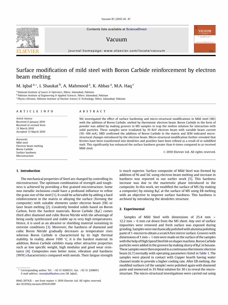
Fig. 2. SEM micrograph of B4C added MS sample after EB melting showing dendrites.
Fig. 3. XRD spectrum B4C added MS sample after EB treatment.
M. Iqbal et al. / Vacuum 85 (2010) 45e4746
scanning electronmicroscope (SEM). XRD analysis was carried out todetect the phases of the composite. Micro-hardness measurementswere done using a load of 98N.
3. Results & discussion
Microstructure of as received MS samples indicating combina-tion of ferrite and pearlite structures is shown in Fig. 1. Similarly,microstructure of MS containing B4C particles is shown in Fig. 2; itreveals that the microstructure is completely different from that ofas received and EB treated MS samples. The ferrite phase has beenre-melted and transformed into dendritic structure due to localizedmelting and high cooling rate produced during EB melting at thesample. Dendrites are formed by faster growth along energeticallyfavorable crystallographic directions. This Dendritic growth [8,9]has large consequences in regards to material properties. Sinceelectron beam melting is localized to a point, the bulk of the Mildsteel sample worked as heat sink. Moreover, the sample was placedon Copper hearth providedwith continuouswater cooling resultingin a rapid cooling of the re-melt. On slow cooling, nucleation of newcrystals would be less resulting in larger size dendritic growth.However, rapid cooling cycle increased the number of nuclei andthus reduced the size of the resulting dendrites that led to theformation of small grains thereby imparting more strength to thematerial [10]. The dendrites formed obstruct the motion of dislo-cations to give substantial hardness. Also, the refinement of pearlitestructure due to EB melting is also clearly evident from Fig. 2. Oncomposite formation at the surface as a result of EB melting, BoronCarbide particles mixed and settled in the matrix of MS as solidparticles. Particle reinforcement stops crack propagation andrestrict dislocations motion in the material. Generally martensitesmake the material hard and brittle and this phase was achievableby adding SiC. However, reinforcement of MS with B4C particlesforms a more ductile product. This is due to deformation processduring thermal shock compression which could potentially lead toenhance the volumetric lattice compression with corresponding
Fig. 1. SEM Micrograph of as received MS samples showing pearlite and ferrite phases.
change in lattice structure. This results in loss of shear strengthwhich makes the material soft [11]. The presence of Boron Carbidephase could not be figured out into EDX results. This might be dueto the fact that; Boron Carbide is very hard phase therefore, uponlocalized heating, thermal stresses are generated which frag-mented relatively larger particles of Boron Carbide into very finesmall particles that mixed with the bulk of material during surfacemelting of MS. This is also evident from the particle size which isreduced from 311�A to 290�A as calculated by Scherer formula [12].
Table 2XRD data for EB Melted MS composite.
Serial No. Composite2-Theta
JCPD Card2-Theta Values
d-Values PhasesIdentified
1 37.6 37.519 2.395 B4C2 44.64 44.59 2.031 a-Fe3 47.94 47.96 1.89 B4C4 65 65.05 1.43 a-Fe5 82.28 82.26 1.17 a-Fe

Table 3Micro hardness of as received & EB melted samples.
Serial no. Avg. diagonal length observed(mm)
Hardness
Asreceived
EBmelted
MS-B4Ccomposite
Asreceived
EBmelted
MS-B4Ccomposite
1 363 328 136 140.7 172.3 1002.42 356 330 142 146.3 170.2 919.53 356 328 150 146.3 172.3 824.04 360 326 143 143.1 174.5 906.65 352 322 144 149.6 178.8 894.16 352 324 155 149.6 176.6 771.77 360 323 143 143.1 177.7 906.68 354 328 150 147.9 172.3 824.09 352 330 152 146.9 170.2 802.510 356 322 142 146.3 178.8 919.5
Average Vicker hardness number 145.98 174.37 877.09
Fig. 4. Vicker hardness comparison.
M. Iqbal et al. / Vacuum 85 (2010) 45e47 47
Also due to being light element it could not be detected by EDX.However, presence of B4C phase was confirmed by XRD as shown inFig. 3. Data for X-ray diffraction of EB melted MS containing B4C isgiven in Table 2. Results clearly indicate that a-phase is found in asreceived samples where as hard Boron Carbide phase is detected byXRD.
Micro-hardness of the as received sample, EB melted and themodified composite surface was measured. Micro-hardness values
of the as received, EB melted and composite samples are giveninTable 3. These are 145HV10 and 877HV10 respectively, suggesting6-times increase in hardness in the modified sample as can be seenin Fig. 4. This enormous increment in hardness is attributed due toB4C reinforcement that created a dendritic structure. Moreover, thereinforced element spread into mild steel matrix due to whichhardness of the molten zone is increased. This combined effect ofreinforcement and dendrites formation resulted in increasedhardness.
4. Conclusions
A composite has been formed on the surface of MS with BoronCarbide particles reinforcement by EB melting. Moreover, EBmelting has transformed ferrite phase into dendritic structure inthematrix and also refined the pearlite phase as well. The grain sizeof the composite is decreased to 290�A. This has increased thesurface hardness of the MS at the fusion zone. The hard phase isidentified by the XRD. Hardness of MS surface was found to beimproved greater than 6-times to that of as received sample.
Acknowledgements
We are grateful to National Institute of Lasers and OptronicsNILOP, Islamabad and Materials Engineering Department ofPakistan Institute of Engineering & Applies Sciences, Nilore,Islamabad for their support during the experimental stage of thiswork. Thanks are also due to Dr. Muhammad Iqbal, for his supportto obtain SEM images.
References
[1] van der Eijk C, Grong Ø, Haakonsen F, Kolbeinsen L, Tranell G. ISIJ Interna-tional 2009;49(7):1046.
[2] Fasasi AY, Pons M, Tassin C, Galerie A, Sainfort G, Polak C. Journal of MaterialsScience 1994;29:5121.
[3] Lazzari R, Besson JM, Baroni S, Corso AD. Physical Review Letters 1999;83(18):3230.
[4] Han Z, Geyang L, Jiawan T, Mingyuan G. Materials Letters 2002;57:899.[5] Ahmad M, Haq MA, Ahmed E, Ali G, Akhter JI, Iqbal M. Applied Surface Science
2009;255:6721.[6] Munawar I, Mohammad R, Sarfarz AB, Fazal A. Vacuum 2004;77(1):19.[7] Munawar I, Fazal A, Mohammad R, Sarfarz AB. Vacuum 2006;(81):499.[8] Yasuji S, Dougherty A, Gollub JP. Physical Review Letters 1986;(12):1260.[9] Hatto J, Klaus S. Metallurgical and Materials Transactions A 1976;7(5):811.
[10] Hisao E, Franqois S, Shigeaki O. ISIJ International 1996;(36):1264.[11] Grady DE. Journal De Physique Iv 1994;(4):385. C8.[12] Agnieszka S, Dariusz O, Agnieszka G, Marcin R, Krzysztof S, Jan K, et al.
Reviews on Advanced Materials Science 2004;(8):143.
Recommended
![Characterization of Corrosion on Outdoor-Exposed …Numerous MMC components with continuous or discontinuous reinforcing fibers and particulates (silicon carbide [SiC], boron carbide](https://img.pdfslide.us/doc/110x75/5fda7789168d495b6511f914/characterization-of-corrosion-on-outdoor-exposed-numerous-mmc-components-with-continuous.jpg)


![INDEX []€¦ · BORON CARBIDE 42 BORON NITRIDE 34 BRINELL 22 BURNT REFRACTORIES 30 CALCIUM ALUMINATE 2 ... TITANIUM DIOXIDE 26 TITANIUM SLAG 39 TUNDISH SLAG 40 TUNGSTEN CARBIDE 42](https://img.pdfslide.us/doc/110x75/60670eb2f72be5794e2aa264/index-boron-carbide-42-boron-nitride-34-brinell-22-burnt-refractories-30-calcium.jpg)