advances.sciencemag.org/cgi/content/full/3/3/e1602076/DC1
Supplementary Materials for
A highly stretchable, transparent, and conductive polymer
Yue Wang, Chenxin Zhu, Raphael Pfattner, Hongping Yan, Lihua Jin, Shucheng Chen,
Francisco Molina-Lopez, Franziska Lissel, Jia Liu, Noelle I. Rabiah, Zheng Chen, Jong Won Chung,
Christian Linder, Michael F. Toney, Boris Murmann, Zhenan Bao
Published 10 March 2017, Sci. Adv. 3, e1602076 (2017)
DOI: 10.1126/sciadv.1602076
The PDF file includes:
section S1. Selection of STEC enhancers
section S2. Mechanical characterization of bulk freestanding films
section S3. Effect of STEC on PEDOT:PSS
section S4. Morphology of PEDOT/STEC film interior
section S5. Microscopy study of the effect of tensile strain on PEDOT/STEC
films
section S6. Electrical properties of PEDOT/STEC films
section S7. Composition of PEDOT/STEC films
section S8. Low-temperature measurements
section S9. FoM for transparent conductors
section S10. Testing geometry for PEDOT films under tensile strain
section S11. Polarized UV-vis-NIR spectra for PEDOT films under tensile strain
section S12. Cycling stability and morphological change of PEDOT with STEC
additives
section S13. Mixed ion-electron conductivity
section S14. PEDOT/STEC as interconnects for FET arrays
table S1. Summary of STEC structures and their effects on the electrical and
mechanical properties of freestanding PEDOT:PSS films (thickness range, 150 to
200 μm) with 45.5 wt % of STEC.
table S2. Summary of mobility and threshold voltage shift for the 3 × 3 transistor
arrays under 0 and 125% strain.
fig. S1. Plot summarizing the conductivity, maximum tensile strain, and Young’s
modulus for freestanding PEDOT:PSS films (~150 μm in thickness) with all
additives investigated in this paper.
fig. S2. Mechanical characterization of bulk freestanding films.
fig. S3. Mechanism behind STEC-induced morphology change for PEDOT:PSS
films.
fig. S4. AFM phase images of PEDOT with various additives.
fig. S5. GIWAXS analyses of PEDOT films.
fig. S6. Diffraction data for PSS and insoluble PEDOT control samples.
fig. S7. Plasticizing effect of STEC on PEDOT and NaPSS individually.
fig. S8. SEM characterization of the cross section of a stretchable PEDOT film.
fig. S9. Optical microscope images of a PEDOT/STEC1 film supported on a
SEBS substrate under various strains.
fig. S10. Optical microscope images of a PEDOT/STEC1 film supported on a
SEBS substrate after being stretched to various strains and returned to its original
length.
fig. S11. Surface profile analyses of PEDOT films after stretching.
fig. S12. Optical microscope images of a PEDOT/STEC1 film upon unloading
from 100% strain.
fig. S13. Optical microscope images of a PEDOT/STEC2 film held under various
tensile strains.
fig. S14. Optical microscope images of a PEDOT/STEC2 film upon stretching to
various tensile strains.
fig. S15. Conductivity values of PEDOT/STEC films processed under different
conditions.
fig. S16. Conductivity of PEDOT/STEC films with various STEC weight %
before and after further STEC solution treatment.
fig. S17. Effect of further doping using STEC solution on spin-coated films.
fig. S18. Chemical composition of PEDOT/STEC films.
fig. S19. Temperature-dependent conductivity and first- and second-order
temperature coefficients for PEDOT films.
fig. S20. Arrhenius plots for temperature dependent conductivity.
fig. S21. Schematic diagrams of tensile testing and conductivity measurement
geometries.
fig. S22. Tension-induced chain-alignment behavior of PEDOT/STEC films.
fig. S23. XPS analysis of film surfaces under 0% versus 100% strain, after
returning from 100% to 0% strain, and after 1000 stretching cycles to 100%
strain.
fig. S24. Cycling stability of PEDOT/STEC1 films.
fig. S25. Cycling stability of PEDOT/STEC2 films.
fig. S26. Mixed ion-electron conductivity measurements.
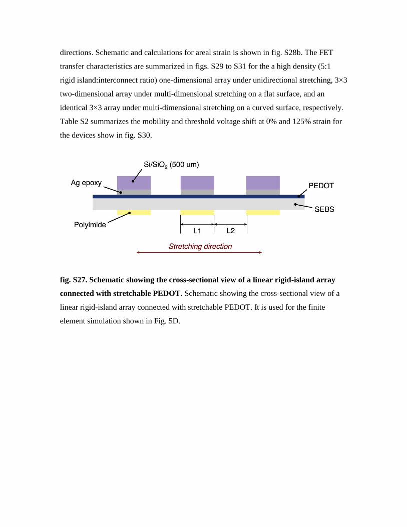
fig. S27. Schematic showing the cross-sectional view of a linear rigid-island array
connected with stretchable PEDOT.
fig. S28. Schematic diagrams illustrating strain calculation for rigid-island
devices.
fig. S29. Schematic and transfer characteristics for a 3 × 1 FET array.
fig. S30. Schematic and transfer characteristics for a 3 × 3 FET array.
fig. S31. A 3 × 3 FET array being stretched on a spherical object.

Other Supplementary Material for this manuscript includes the following:
(available at advances.sciencemag.org/cgi/content/full/3/3/e1602076/DC1)
video S1 (.mov format). A stretchable LED device poked with a sharp object.
video S2 (.mov format). Twisting and stretching of a stretchable LED device.
video S3 (.mov format). A 3 × 3 FET array stretched on a spherical object.
Supplementary Materials
section S1. Selection of STEC enhancers
In order to increase the stretchability of PEDOT:PSS, plasticizers such as Zonyl or Triton
needs to be incorporated. PEDOT becomes more stretchable with a higher plasticizer
concentration; however, the increase in plasticizer (an insulator) concentration usually
causes the conductivity to decrease, which poses as a significant issue for their
application as electrodes or interconnects.
We found that a variety of small molecule ionic additives can serve as effective STECs
for PEDOT:PSS for inducing both high stretchability and high conductivity. Their ionic
nature allowed them to simultaneously tune morphology and dope the polymer, while
also promoting effective phase separation between PEDOT and PSS and enhancing the
crystallinity of the PEDOT-rich domains (mechanism and selection guideline discussed
in main text and Supplemental Section 2). Figure S1 summarizes the key bulk material
characteristics: conductivity, maximum tensile strain, and Young’s modulus, for free-
standing films that are approximately 200 μm thick. We chose the additives that lead to
conductivity over 100 S/cm and a maximum tensile strain above 100%, STEC1-3, for
further investigation. The names and structures of the additives are shown in table S1.
The conductivity values for these thick drop-casted films are lower than those of the thin
spin-coated films presented in Fig. 4a and figs. S15 and S16. This is a general
phenomenon that has been observed for PEDOT:PSS films (Appl. Phys. Express 2016,
9(5): 051601). This difference is attributed to morphology difference due to processing
methods and drying kinetics. Additionally, in this work, the spin-coated films were
further rinsed with STEC solution while the drop-casted films were not further treated.
Note that the free-standing films were necessary for mechanical property testing, and
their conductivities measured to serve as a guide for us to identify the most suitable
STEC additives among the large amount of possibilities (table S1 and fig. S1). STEC1, 2,

3 were identified as the highest performing STEC, and their electrical properties were
further enhanced and studied in detail (Fig. 4a and figs. S15 and S16).
table S1. Summary of STEC structures and their effects on the electrical and
mechanical properties of freestanding PEDOT:PSS films (thickness range, 150 to
200 μm) with 45.5 wt % of STEC.
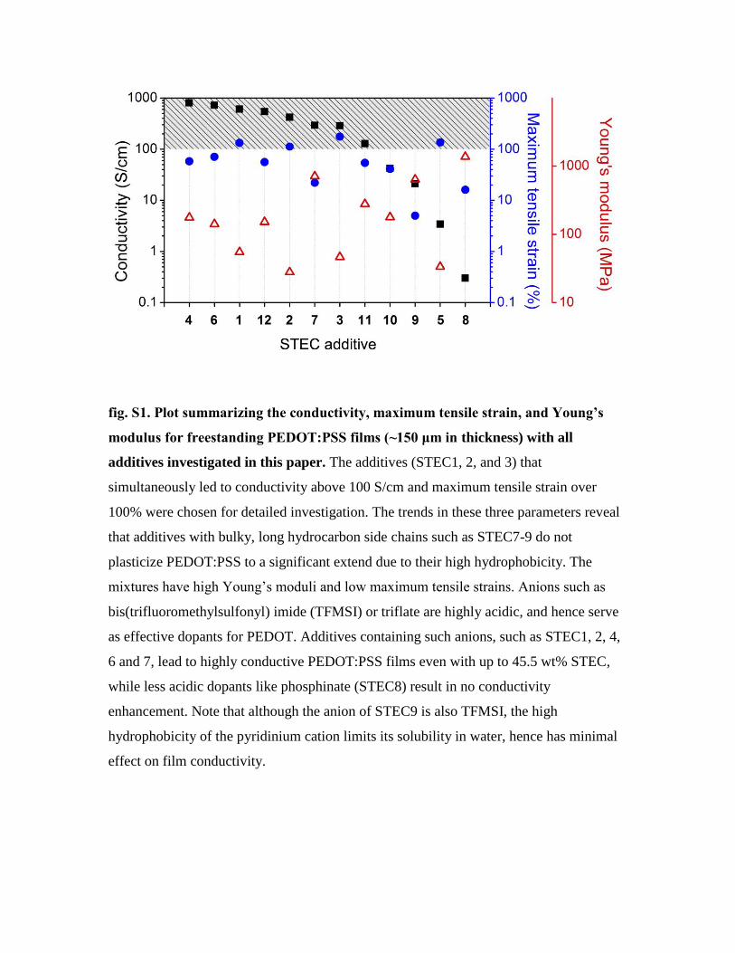
fig. S1. Plot summarizing the conductivity, maximum tensile strain, and Young’s
modulus for freestanding PEDOT:PSS films (~150 μm in thickness) with all
additives investigated in this paper. The additives (STEC1, 2, and 3) that
simultaneously led to conductivity above 100 S/cm and maximum tensile strain over
100% were chosen for detailed investigation. The trends in these three parameters reveal
that additives with bulky, long hydrocarbon side chains such as STEC7-9 do not
plasticize PEDOT:PSS to a significant extend due to their high hydrophobicity. The
mixtures have high Young’s moduli and low maximum tensile strains. Anions such as
bis(trifluoromethylsulfonyl) imide (TFMSI) or triflate are highly acidic, and hence serve
as effective dopants for PEDOT. Additives containing such anions, such as STEC1, 2, 4,
6 and 7, lead to highly conductive PEDOT:PSS films even with up to 45.5 wt% STEC,
while less acidic dopants like phosphinate (STEC8) result in no conductivity
enhancement. Note that although the anion of STEC9 is also TFMSI, the high
hydrophobicity of the pyridinium cation limits its solubility in water, hence has minimal
effect on film conductivity.

section S2. Mechanical characterization of bulk freestanding films
fig. S2. Mechanical characterization of bulk freestanding films. (a) Stress/strain
behavior of freestanding PEDOT films with various additives. Inset provides a zoomed-in
view over the lower strain section where the elastic-to-plastic transition occurs. (b) Stress
relaxation, (c) Strain cycling (arrows indicating loading and unloading paths) and (d)
storage and loss moduli of PEDOT/STEC2 films.
To elucidate the mechanical properties of the stretchable PEDOT, the stress/strain
behavior of the free-standing films with various STEC additives are compared to the
control sample without STEC but with DMSO, a common polar additive for enhancing
PEDOT:PSS conductivity (Displays 2013, 34(5): 423-436), was studied (Fig. 1f). The
control film ruptures when 18% strain was applied, confirming previous reports that
conventional PEDOT has poor stretchability (Adv. Funct. Mater. 2012, 22(2): 421-428).
On the other hand, the PEDOT films with STEC additives 1, 2, 3 have greatly enhanced
maximum tensile strain of 133%, 112%, and 176%, respectively (Fig. 1f). This
enhancement in stretchability is attributed to a combination of the fibrous morphology
(Fig. 3, h to k) and the plasticizing effect of STEC molecules in the disordered domains
in PEDOT:PSS (Supplementary Section 3c). The most stretchable films mostly possess
fibrous morphology (Fig. 3, h to k and fig. S4), which could be a significant contributing
factor for achieving high stretchability, as proposed by previous studies (Adv. Funct.
Mater. 2015, 25(3): 427-436).
To confirm the plasticizing effects of STEC on PEDOT:PSS, STEC2 was separately
mixed with NaPSS and insoluble PEDOT as a model system (fig. S7). Incorporating 45.5
and 62.5 wt% of STEC2 into the insoluble, powdery PEDOT lead to a paste and gel-like
substance, respectively, suggesting the STEC can effectively swell PEDOT chains (fig.
S7, a to d) (Science 2008, 321(5895): 1468-1472). Mechanical tests could not be carried
out since the paste does not possess good film forming properties, likely due to the low
molecular weight of PEDOT. On the other hand, including STEC2 into NaPSS led to a
significant increase in stretchability and a much reduced Young’s modulus, illustrating
the plasticizing effect of STEC for PSS (fig. S7e). Therefore, due to the ability of STECs
to serve as effective plasticizers for both PEDOT and PSS, STEC addition led to
significantly enhanced maximum tensile strains and reduced Young’s moduli.
To further characterize the mechanical properties of the PEDOT/STEC films, stress
relaxation, strain cycling, and frequency sweep experiments were carried out (fig. S2, b
to d). A relaxation time of approximately 72 seconds was measured (fig. S2b). We loaded
and unloaded a PEDOT/STEC film with a strain rate of 0.1/min and reloaded the sample
to a larger strain after waiting for 5 min between two cycles (fig. S2c). The stress-strain
curves showed hysteresis between loading and unloading. When the film was stretched
beyond 20% strain, the film length change became only partially reversible, indicating
the viscoplastic response of the film. In the frequency sweep experiment shown in fig.
S2d, the storage modulus is higher than the loss modulus during the entire frequency
range, confirming the film is a solid rather than a fluid despite the high concentration of
STEC. SEM analysis of the film cross-section also shows a densely packed, solid interior
(fig. S8, a to b).
section S3. Effect of STEC on PEDOT:PSS
The STEC additives have three effects on PEDOT:PSS: (a) inducing phase separation
forming distinctive PEDOT- and PSS-rich domains; (b) enhancing the crystallinity of the
PEDOT-rich domains; (c) plasticizing the amorphous regions of PEDOT and PSS.
(a) Effect on phase separation and morphology
Previous literature proposed that the Clevios PEDOT:PSS PH1000 dispersion that we
used in this study has a core-shell structure (Displays 2013, 34(5): 423-436). PSS is water
soluble, and the sulfonate groups serve as dopants for the conductive PEDOT. The low
molecular weight PEDOT (MW ~1000-2500 Da) is insoluble in water; hence, it adheres
to segments of the high molecular weight PSS chains (MW ~400,000 Da) through
Coulombic attractions. These ionic complexes form coiled, globular structures in water
where the hydrophilic PSS-rich shell shields the hydrophobic PEDOT-rich core from
water, forming a colloidal dispersion. However, the insulating PSS shells become a
barrier for charge transport between the PEDOT-rich domains, resulting in low
conductivity (<1 S/cm) in films.
Previous reports have suggested that polar or ionic substances such as ethylene glycol or
ionic liquid can induce the merging of PEDOT/PSS particles (fig. S3a) (Displays 2013,
34(5): 423-436; Macromolecules 2008, 41(16): 5971-5973). When STEC molecules such
as STEC are incorporated into the PEDOT:PSS system, due to their small sizes, they can
more easily interact with both the positively-charged PEDOT and the negatively-charged
PSS chains. This leads to a charge screening effect that weakens the Coulombic
interactions between the PEDOT and PSS chains. Therefore, larger PEDOT-rich domains
can form due to the dissociation between some PEDOT and PSS, which aids in
enhancing the conductivity of the films (Displays 2013, 34(5): 423-436; Adv. Funct.
Mater. 2012, 22(13): 2723-2727). In fact, dynamic light scattering profiles (fig. S3b)
show that the average particle sizes of the PEDOT:PSS colloids increase significantly
upon the addition of various STEC additives, confirming the mechanism depicted in fig.
S3a.
This STEC-induced charge screening effect is also reflected by the AFM images of the
solid films (fig. S4). The PEDOT:PSS film with 5% DMSO and without STEC enhancers
show a rather featureless morphology (fig. S4a). However, clear domains of larger
feature sizes are formed with the addition of any of the STEC enhancers (fig. S4, b to j).
Note that the morphology of the films is not the sole factor in determining the film
conductivity. fig. S4, c to f illustrate the four most conductive PEDOT/STEC systems,
while fig. S4b corresponds to a film that is poorly conductive (0.3 S/cm). One possible
reason responsible for the low conductivity is that the PEDOT-rich grains in PEDOT/IL8
do not appear to be well-connected, hence leading to a poor conduction pathway. The
precise mechanism is still under investigation.
The STEC-induced charge screening can also have an effect on the chain conformation of
polyelectrolyte complexes such as PEDOT:PSS (Displays 2013, 34(5): 423-436). The
weakened Coulombic interaction between PEDOT and PSS allows PEDOT to be
partially dissociated from the highly coiled PSS and adopt a more planar conformation,
which promotes delocalization of charge carriers that can lead to an increase in
conductivity. Raman spectra of the PEDOT/STEC films show a red shift of the Cα=Cβ
vibration peak (~1445 cm-1) and narrowing of the peak compared to the PEDOT without
any additives (Fig. 3a). This change indicates that a higher proportion of the resonant
structure of PEDOT chains is turning from the benzoid structure in the pure PEDOT:PSS
films to the more planar quinoid structure in PEDOT/STEC (Macromolecules 2009,
42(12): 4141-4147; Adv. Funct. Mater. 2005, 15(2): 203-208; Synth. Met. 2001, 125(3):
325-329). In addition, compared to the plain PEDOT:PSS films, UV-vis-NIR spectra of
the PEDOT/STEC films exhibit a more prominent free-carrier tail that extends into NIR
and a less well-defined peak around 800 nm. Such results suggest better delocalization of
charges along the PEDOT backbone (Synth. Met. 2000, 110(1): 79-83; Solid State
Commun. 1986, 59(7): 415-421), another indication for a less coiled chain conformation,
which leads to enhanced conductivity.

fig. S3. Mechanism behind STEC-induced morphology change for PEDOT:PSS
films. (a) Schematic representation illustrating the effect of STEC on enhancing the
phase separation of the PEDOT-rich and PSS-rich domains. (b) and (c) show the average
particle sizes in PEDOT:PSS aqueous dispersions with different additive concentrations.
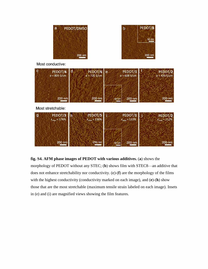
fig. S4. AFM phase images of PEDOT with various additives. (a) shows the
morphology of PEDOT without any STEC; (b) shows film with STEC8—an additive that
does not enhance stretchability nor conductivity. (c)-(f) are the morphology of the films
with the highest conductivity (conductivity marked on each image), and (e)-(h) show
those that are the most stretchable (maximum tensile strain labeled on each image). Insets
in (e) and (i) are magnified views showing the film features.
(b) Effect on the crystalline regions
As we noted in the previous section, not all STEC additives lead to an enhancement of
conductivity despite the clearer phase separation between the PEDOT- and PSS-rich
regions. This observation indicates there are other factors at play.
PEDOT:PSS is a semicrystalline polymer, where small PEDOT-rich crystallites are
distributed within a disordered matrix. Such structure is reflected by the high background
scattering intensity in the GIWAXS patterns (fig. S5, a to e). GIWAXS analysis shows
that the PEDOT/STEC with high conductivity, such as PEDOT/STEC1 or 2, exhibit
significantly higher crystallinity (fig. S5, d and e) despite being highly stretchable,
suggesting the STEC plasticizers are likely distributed in the disordered matrix. The
corresponding near out-of-plane intensity plots are shown in fig. S5, f and g. For the
PEDOT film without any STEC additives, three peaks were observed along qz: qz = 0.57
Å-1 (d = 11.2 Å), 1.33 Å-1 (d = 4.9 Å), and 1.87 Å-1 (d = 3.4 Å), which can be indexed as
PEDOT (200), PSS amorphous scattering, and PEDOT (010), respectively (Proc. Natl.
Acad. Sci. 2015, 112(46): 14138-14143; Synth. Met. 2000, 113(1–2): 93-97). With the
addition of STEC, the diffraction peak corresponding to lamella packing, (200), becomes
much better defined and increase in relative intensity (fig. S5, d and e). Meanwhile with
the addition of ILs, a new peak emerges at qz = ~0.89 Å-1 (d = ~6.8 Å), which was also
reported elsewhere in the literature and assigned to PEDOT, but no definitive index was
reported. In addition, we observed this peak in the non-soluble PEDOT:PF6 system (fig.
S6), further confirming it arises from PEDOT scattering. The more profound presence of
lamella packing peaks indicates the PEDOT/STEC samples have better ordered
crystalline domains than that without any STEC additive. Interestingly, the (200) d-
spacing increases with increased STEC contents in the films, which is accompanied by a
slight decrease in d-spacing for the (010) peak (from 3.4 Å to 3.3 Å). This again suggests
an increase in the degree of molecular ordering and local crystallinity (Phys. Rev. Lett.
2012, 109(10): 106405). Similar diffraction results have been reported previously in
highly conductive PEDOT:PSS obtained by H2SO4 treatment (Adv. Mater. 2014, 26(14):
2268-2272; Adv. Mater. 2015, 27(22): 3391-3397).
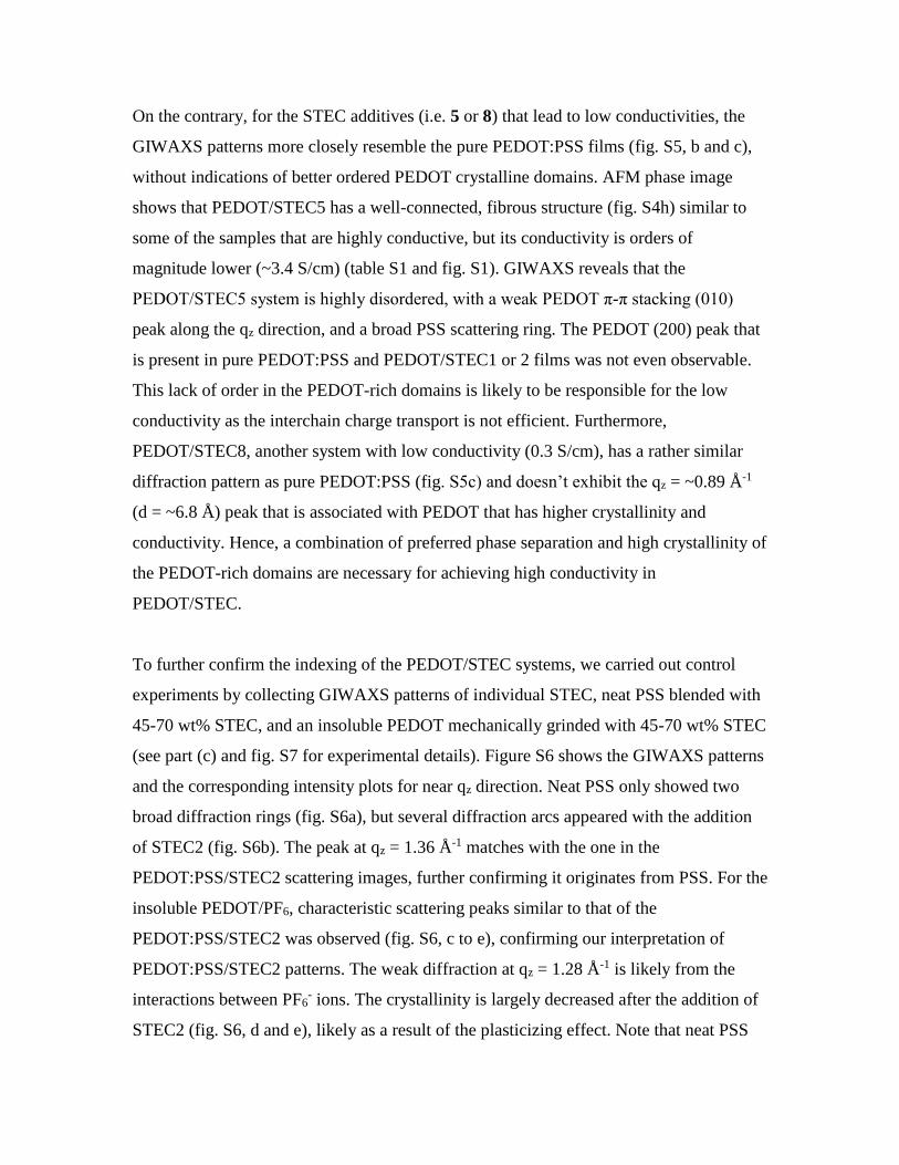
On the contrary, for the STEC additives (i.e. 5 or 8) that lead to low conductivities, the
GIWAXS patterns more closely resemble the pure PEDOT:PSS films (fig. S5, b and c),
without indications of better ordered PEDOT crystalline domains. AFM phase image
shows that PEDOT/STEC5 has a well-connected, fibrous structure (fig. S4h) similar to
some of the samples that are highly conductive, but its conductivity is orders of
magnitude lower (~3.4 S/cm) (table S1 and fig. S1). GIWAXS reveals that the
PEDOT/STEC5 system is highly disordered, with a weak PEDOT π-π stacking (010)
peak along the qz direction, and a broad PSS scattering ring. The PEDOT (200) peak that
is present in pure PEDOT:PSS and PEDOT/STEC1 or 2 films was not even observable.
This lack of order in the PEDOT-rich domains is likely to be responsible for the low
conductivity as the interchain charge transport is not efficient. Furthermore,
PEDOT/STEC8, another system with low conductivity (0.3 S/cm), has a rather similar
diffraction pattern as pure PEDOT:PSS (fig. S5c) and doesn’t exhibit the qz = ~0.89 Å-1
(d = ~6.8 Å) peak that is associated with PEDOT that has higher crystallinity and
conductivity. Hence, a combination of preferred phase separation and high crystallinity of
the PEDOT-rich domains are necessary for achieving high conductivity in
PEDOT/STEC.
To further confirm the indexing of the PEDOT/STEC systems, we carried out control
experiments by collecting GIWAXS patterns of individual STEC, neat PSS blended with
45-70 wt% STEC, and an insoluble PEDOT mechanically grinded with 45-70 wt% STEC
(see part (c) and fig. S7 for experimental details). Figure S6 shows the GIWAXS patterns
and the corresponding intensity plots for near qz direction. Neat PSS only showed two
broad diffraction rings (fig. S6a), but several diffraction arcs appeared with the addition
of STEC2 (fig. S6b). The peak at qz = 1.36 Å-1 matches with the one in the
PEDOT:PSS/STEC2 scattering images, further confirming it originates from PSS. For the
insoluble PEDOT/PF6, characteristic scattering peaks similar to that of the
PEDOT:PSS/STEC2 was observed (fig. S6, c to e), confirming our interpretation of
PEDOT:PSS/STEC2 patterns. The weak diffraction at qz = 1.28 Å-1 is likely from the
interactions between PF6- ions. The crystallinity is largely decreased after the addition of
STEC2 (fig. S6, d and e), likely as a result of the plasticizing effect. Note that neat PSS
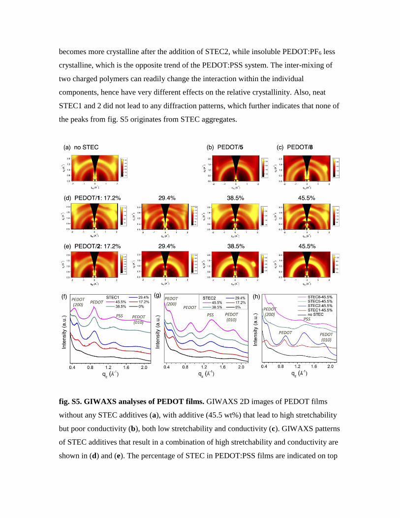
becomes more crystalline after the addition of STEC2, while insoluble PEDOT:PF6 less
crystalline, which is the opposite trend of the PEDOT:PSS system. The inter-mixing of
two charged polymers can readily change the interaction within the individual
components, hence have very different effects on the relative crystallinity. Also, neat
STEC1 and 2 did not lead to any diffraction patterns, which further indicates that none of
the peaks from fig. S5 originates from STEC aggregates.
fig. S5. GIWAXS analyses of PEDOT films. GIWAXS 2D images of PEDOT films
without any STEC additives (a), with additive (45.5 wt%) that lead to high stretchability
but poor conductivity (b), both low stretchability and conductivity (c). GIWAXS patterns
of STEC additives that result in a combination of high stretchability and conductivity are
shown in (d) and (e). The percentage of STEC in PEDOT:PSS films are indicated on top
of the respective 2D images. (f) and (g) are the line cut plots for the scattering images in
(d) and (e), respectively, averaging the scattering intensity within a 30-degree wide sector
around vertical qz direction. (h) combines the line cut plots of PEDOT:PSS films without
any STEC additives and those with 45.5 wt% of different additives for comparison.
fig. S6. Diffraction data for PSS and insoluble PEDOT control samples. (a)-(d)
GIWAXS data for (a) neat PSS (MW ~200,000 Da), (b) PSS + 45.5 wt% STEC2, (c)
PEDOT/PF6, and (d) PEDOT/PF6 + 45.5 wt% of STEC2. (e) Line cut plots of (a)-(d)
along the qz direction (30-degree width sector) compared to that of PEDOT:PSS with
45.5 wt% of STEC2.
(c) Effect on mechanical properties
Despite the much-enhanced crystallinity of the PEDOT films with STEC1 or 2 addition,
these films also possess higher stretchability. The increase in crystallinity mostly
corresponds to the PEDOT-rich domains, which suggests the plasticizers are likely
dispersed in the disordered matrix. To probe the interaction between STEC and
PEDOT:PSS, we incorporated STEC into PEDOT and NaPSS separately. Insoluble
PEDOT:PF6 was synthesized according to a previous procedure. The product is a black

powdery substance (fig. S7a). Vigorous sonication of this powder in water for 1 h yielded
a dark dispersion (fig. S7b, left). However, the particles settled out within minutes,
confirming its insoluble nature (fig. S7b, right). When 45.5 wt% of STEC2 was grinded
with the PEDOT powder, a homogeneous paste was formed (fig. S7c), while
incorporating 62.5 wt% of STEC2 led to a gel-like substance (fig. S7d). Therefore, STEC
can serve as an effective plasticizer for the PEDOT component in PEDOT:PSS.
Previously, STEC has been shown as an effective medium for dispersing the otherwise
insoluble CNTs, which allowed for their homogeneous distribution in an elastic fluoro-
polymer as stretchable conductors.5 The STEC has a similar effect in dispersing the
insoluble PEDOT here. Unfortunately, the paste with 45.5 wt% STEC2 has poor film
forming property, likely due to the low molecular weight of PEDOT, hence prohibited it
from tensile strain/stress testing.
45.5 wt% of STEC2 was also incorporated into NaPSS. We chose the MW ~200,000 Da
grade as it is the closest in molecular weight to the PSS in Clevios PH1000 (400,000 Da)
(Displays 2013, 34(5): 423-436). A much lower modulus and a significantly enhanced
maximum tensile strain is observed for the NaPSS film with STEC compared to the
pristine NaPSS, indicating its plasticizing effectiveness. Therefore, due to the strong
interaction between STEC and both PEDOT and PSS components, we propose that STEC
plasticizers are incorporated in the disordered domains of PEDOT:PSS, rendering the
films highly stretchable.
Furthermore, it has been proposed that the fibrous network formed from phase separation
between PEDOT and PSS are crucial for achieving stretchability (Adv. Funct. Mater.
2015, 25(3): 427-436). We observe that the PEDOT/STEC films with the highest
stretchability all possess some level of fibrous or web-like morphology (fig. S4, g to j).
However, morphology alone does not guarantee high stretchability; for instance,
PEDOT/STEC6 (fig. S4d) also exhibit well-defined fibrous morphology, but is only
moderately stretchable (maximum tensile strain = 71% as a free-standing film).
Therefore, we propose that it is the combination of the effectiveness of individual STEC

enhancers with the fibrous morphology that results in high stretchability observed in
select PEDOT/STEC systems.
fig. S7. Plasticizing effect of STEC on PEDOT and NaPSS individually. (a) Picture of
insoluble PEDOT:PF6 powder. After sonicating the powder in water for 1 h, an
apparently homogeneous dispersion is formed (b, left). However, the particles precipitate
out within minutes (b, right), illustrating its insoluble, non-dispersible nature. STEC2 was
added to this powder and thoroughly mixed using a mortar and pestle. Picture in (c)
shows the paste that was formed after dispersing this PEDOT with 45.5 wt% STEC2, and
(d) shows the gel-like substance with 62.5% STEC2 addition. These results illustrate that
the STEC can effectively disperse the insoluble PEDOT and have a plasticizing effect.
Similarly, 45.5 wt% of STEC2 was added to polystyrenesulfonate sodium (NaPSS) with
a molecular weight of 200,000 Da. This molecular weight is chosen as it is the
commercially available grade with the closest molecular weight match to those in the
PEDOT:PSS (400,000 Da). (e) shows the stress/strain curves of the pure NaPSS films
and after the addition of STEC. A much enhanced maximum tensile strain is achieved,
which illustrate that STEC has a plasticizing effect for both the PEDOT and the PSS
phase.

section S4. Morphology of PEDOT/STEC film interior
SEM analyses show that the PEDOT/STEC2 films have a solid and densely packed
cross-section despite the high STEC percentage, indicating the STEC is well dispersed in
the polymer network.
fig. S8. SEM characterization of the cross section of a stretchable PEDOT film. (a)
SEM image showing the solid cross-section of a PEDOT film with 45.5% STEC2; (b)
offers a zoomed view of (a).
section S5. Microscopy study of the effect of tensile strain on PEDOT/STEC films.
fig. S9. Optical microscope images of a PEDOT/STEC1 film supported on a SEBS
substrate under various strains.

fig. S10. Optical microscope images of a PEDOT/STEC1 film supported on a SEBS
substrate after being stretched to various strains and returned to its original length.
Folds are formed in the film after stretching as seen from AFM in fig. S11.

fig. S11. Surface profile analyses of PEDOT films after stretching. (a)-(c) Optical
Microscope images at various magnifications showing a PEDOT/STEC1 film at 0%
strain after cycling 1000 times to 100% strain. (d) and (e) are the corresponding AFM
images showing folds in the film.
fig. S12. Optical microscope images of a PEDOT/STEC1 film upon unloading from
100% strain. (a) At 80% strain, (b) at 70% strain where wrinkles are seen, indicating the
onset of plastic deformation.
fig. S13. Optical microscope images of a PEDOT/STEC2 film held under various
tensile strains.
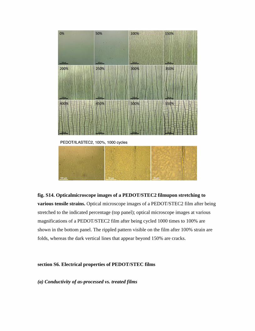
fig. S14. Opticalmicroscope images of a PEDOT/STEC2 filmupon stretching to
various tensile strains. Optical microscope images of a PEDOT/STEC2 film after being
stretched to the indicated percentage (top panel); optical microscope images at various
magnifications of a PEDOT/STEC2 film after being cycled 1000 times to 100% are
shown in the bottom panel. The rippled pattern visible on the film after 100% strain are
folds, whereas the dark vertical lines that appear beyond 150% are cracks.
section S6. Electrical properties of PEDOT/STEC films
(a) Conductivity of as-processed vs. treated films
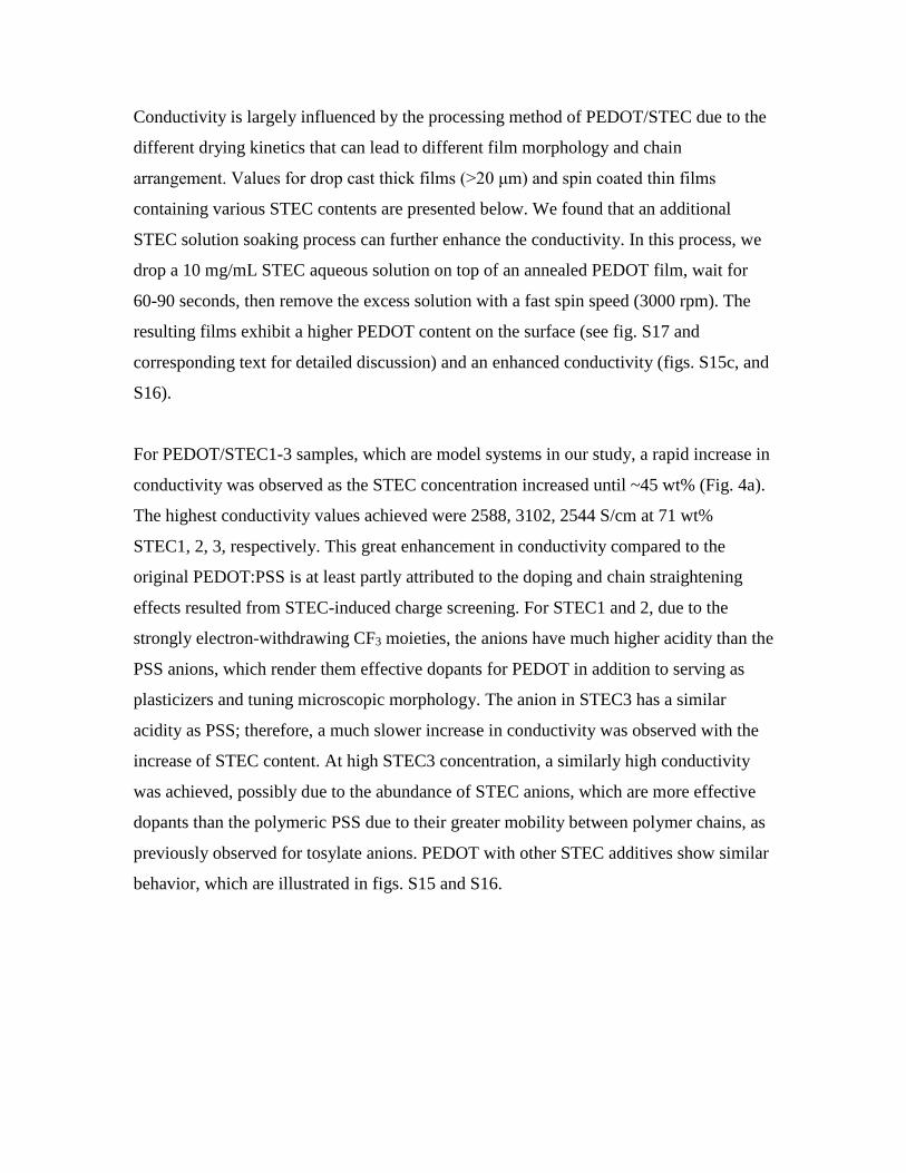
Conductivity is largely influenced by the processing method of PEDOT/STEC due to the
different drying kinetics that can lead to different film morphology and chain
arrangement. Values for drop cast thick films (>20 μm) and spin coated thin films
containing various STEC contents are presented below. We found that an additional
STEC solution soaking process can further enhance the conductivity. In this process, we
drop a 10 mg/mL STEC aqueous solution on top of an annealed PEDOT film, wait for
60-90 seconds, then remove the excess solution with a fast spin speed (3000 rpm). The
resulting films exhibit a higher PEDOT content on the surface (see fig. S17 and
corresponding text for detailed discussion) and an enhanced conductivity (figs. S15c, and
S16).
For PEDOT/STEC1-3 samples, which are model systems in our study, a rapid increase in
conductivity was observed as the STEC concentration increased until ~45 wt% (Fig. 4a).
The highest conductivity values achieved were 2588, 3102, 2544 S/cm at 71 wt%
STEC1, 2, 3, respectively. This great enhancement in conductivity compared to the
original PEDOT:PSS is at least partly attributed to the doping and chain straightening
effects resulted from STEC-induced charge screening. For STEC1 and 2, due to the
strongly electron-withdrawing CF3 moieties, the anions have much higher acidity than the
PSS anions, which render them effective dopants for PEDOT in addition to serving as
plasticizers and tuning microscopic morphology. The anion in STEC3 has a similar
acidity as PSS; therefore, a much slower increase in conductivity was observed with the
increase of STEC content. At high STEC3 concentration, a similarly high conductivity
was achieved, possibly due to the abundance of STEC anions, which are more effective
dopants than the polymeric PSS due to their greater mobility between polymer chains, as
previously observed for tosylate anions. PEDOT with other STEC additives show similar
behavior, which are illustrated in figs. S15 and S16.

fig. S15. Conductivity values of PEDOT/STEC films processed under different
conditions. Conductivity of PEDOT/STEC films in relation to the ionic liquid additive
contents prepared by (a) drop casting (thick films of 20-200 μm), (b) spin coating (thin
films of 50-200 nm), and (c) spin coating then further treated with the corresponding
STEC aqueous solution.
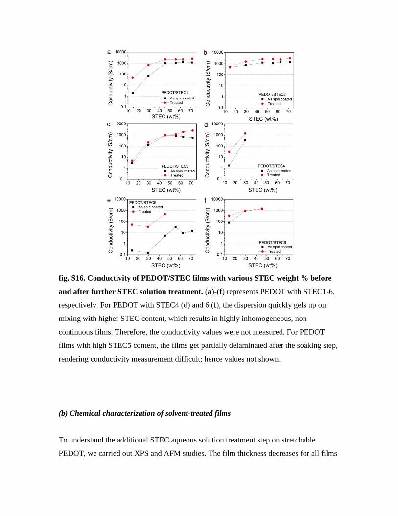
fig. S16. Conductivity of PEDOT/STEC films with various STEC weight % before
and after further STEC solution treatment. (a)-(f) represents PEDOT with STEC1-6,
respectively. For PEDOT with STEC4 (d) and 6 (f), the dispersion quickly gels up on
mixing with higher STEC content, which results in highly inhomogeneous, non-
continuous films. Therefore, the conductivity values were not measured. For PEDOT
films with high STEC5 content, the films get partially delaminated after the soaking step,
rendering conductivity measurement difficult; hence values not shown.
(b) Chemical characterization of solvent-treated films
To understand the additional STEC aqueous solution treatment step on stretchable
PEDOT, we carried out XPS and AFM studies. The film thickness decreases for all films

after the STEC solution soaking regardless of the STEC used (fig. S17a). XPS of the film
surface reveals that a higher PEDOT content is exposed (peak ~163-165 eV) and the
PSS+STEC amount (~168-170 eV) decreases (fig. S17b). Similar observations can be
seen from the AFM images in fig. S17, c to f, as the PEDOT phase content is visibly
higher, as indicated by the more fiber-like structures. Control experiments of dropping
water instead of STEC solution on top of the annealed PEDOT films lead to a similar
decrease in thickness and increase in conductivity. We used STEC aqueous solutions here
in order to wash away PSS but minimize STEC loss as they serve as plasticizers.
fig. S17. Effect of further doping using STEC solution on spin-coated films. (a)
Change in film thickness (STEC content = 45.5%); (b) XPS spectra comparing the
change in chemical composition; (c) height and (d) phase AFM images of a
PEDOT/STEC1 film obtained by spin coating; (e) height and (f) phase AFM images of
the same film after further doping with STEC solution.
section S7. Composition of PEDOT/STEC films
fig. S18. Chemical composition of PEDOT/STEC films. (a)-(b) XPS spectra of a
PEDOT/STEC2 film with various C60 ion gun sputtering duration for S 2p (a) and F 1s
(b). (c) Atomic ratio between the integrated S 2p and F 1s peaks showing the relative
ratios of the various elements in the film. (d) Relative composition of PEDOT, PSS, and
STEC2 along at various depths. The composition of STEC2 (S 2p) is determined by the
stoichiometric conversion of the F 1s peak based on the molecular structure. PSS (S 2p)
composition can thus be obtained by subtracting the STEC2 (S 2p) percentage from the
PSS+STEC2 (S 2p) values in (c).

section S8. Low-temperature measurements
fig. S19. Temperature-dependent conductivity and first- and second-order
temperature coefficients for PEDOT films. (a) Temperature-dependent conductivity of
PEDOT films with various additives; (b) equation for extracting temperature coefficients;
(c) Table showing the first and second order temperature coefficients of the films.
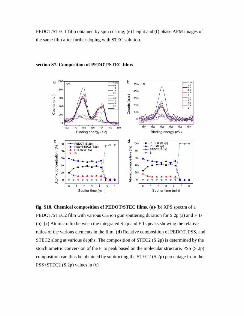
fig. S20. Arrhenius plots for temperature dependent conductivity. Arrhenius plots for
PEDOT with various additives upon (a) cooling and (b) heating; (c) schematic
illustrating the measurement geometry; (d) equations for extracting activation energy
from the temperature dependent conductivity behavior.
section S9. FoM for transparent conductors
A key standard for evaluating a transparent conductor is its figure of merit (FoM), which
is defined as the ratio of its direct current conductivity (σdc) to optical conductivity (σop):
𝐹𝑜𝑀 =𝜎𝑑𝑐
𝜎𝑜𝑝(𝜆)=
188.5 Ω
𝑅𝑠ℎ ∙ (𝑇(𝜆)−12 − 1)
,
where Rsh is the sheet resistance, T is the optical transparency at a specified wavelength λ
(550 nm). A FoM of 35 is typically the required benchmark value for a transparent
conductor to be commercially viable (Adv. Funct. Mater. 2011, 21(6): 1076-1081). Our
stretchable PEDOT/STEC exhibit FoM above 100 for all thicknesses tested (Fig. 4e),
with a value as high as 142 for the film with 96% transmittance. It surpasses the previous
highest value from spin-casted PEDOT films (i.e. FoM = 72 for H2SO4-treated films).

section S10. Testing geometry for PEDOT films under tensile strain
A dumbbell geometry is used for the resistance vs. strain experiments to promote uniform
deformation within the stretched region (fig. S21a). Four parallel EGaIn electrodes were
deposited either in parallel or perpendicular to the stretching direction to probe
anisotropic conductivity (fig. S21b). The dimension change between the electrodes was
measured at each strain value and the film thickness change was extracted using optical
measurements. Conductivity values were then calculated using the equation in fig. S21c.
fig. S21. Schematic diagrams of tensile testing and conductivity measurement
geometries. (a) Geometry of PEDOT films used for testing resistance change under
tensile strain. The dashed rectangle represents area being stretched. (b) Four-point probe
measurement geometry and (c) equation for calculating conductivity.
section S11. Polarized UV-vis-NIR spectra for PEDOT films under tensile strain
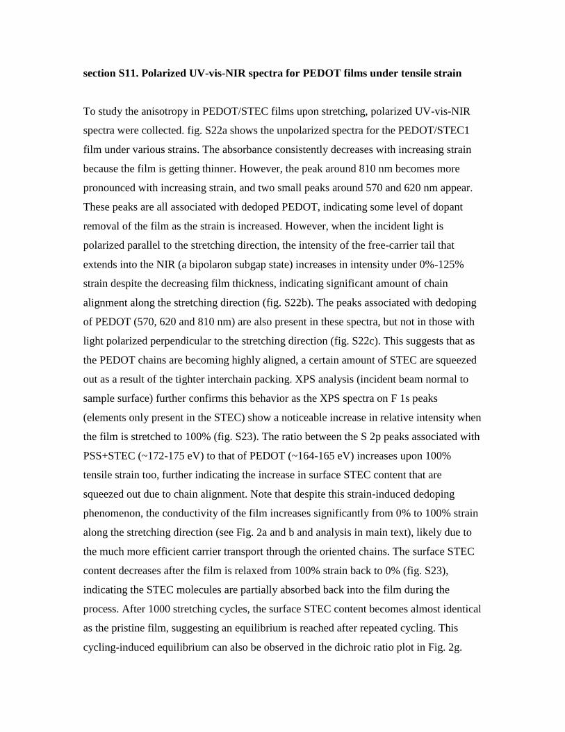
To study the anisotropy in PEDOT/STEC films upon stretching, polarized UV-vis-NIR
spectra were collected. fig. S22a shows the unpolarized spectra for the PEDOT/STEC1
film under various strains. The absorbance consistently decreases with increasing strain
because the film is getting thinner. However, the peak around 810 nm becomes more
pronounced with increasing strain, and two small peaks around 570 and 620 nm appear.
These peaks are all associated with dedoped PEDOT, indicating some level of dopant
removal of the film as the strain is increased. However, when the incident light is
polarized parallel to the stretching direction, the intensity of the free-carrier tail that
extends into the NIR (a bipolaron subgap state) increases in intensity under 0%-125%
strain despite the decreasing film thickness, indicating significant amount of chain
alignment along the stretching direction (fig. S22b). The peaks associated with dedoping
of PEDOT (570, 620 and 810 nm) are also present in these spectra, but not in those with
light polarized perpendicular to the stretching direction (fig. S22c). This suggests that as
the PEDOT chains are becoming highly aligned, a certain amount of STEC are squeezed
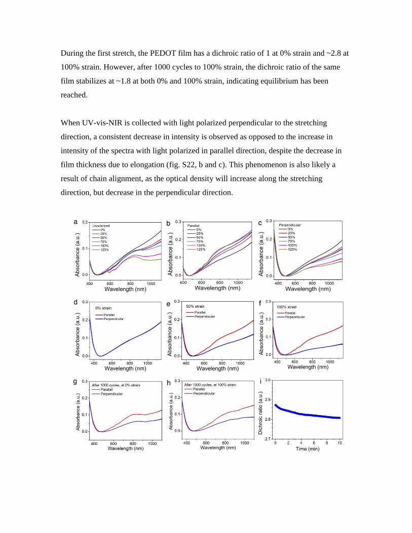
out as a result of the tighter interchain packing. XPS analysis (incident beam normal to
sample surface) further confirms this behavior as the XPS spectra on F 1s peaks
(elements only present in the STEC) show a noticeable increase in relative intensity when
the film is stretched to 100% (fig. S23). The ratio between the S 2p peaks associated with
PSS+STEC (~172-175 eV) to that of PEDOT (~164-165 eV) increases upon 100%
tensile strain too, further indicating the increase in surface STEC content that are
squeezed out due to chain alignment. Note that despite this strain-induced dedoping
phenomenon, the conductivity of the film increases significantly from 0% to 100% strain
along the stretching direction (see Fig. 2a and b and analysis in main text), likely due to
the much more efficient carrier transport through the oriented chains. The surface STEC
content decreases after the film is relaxed from 100% strain back to 0% (fig. S23),
indicating the STEC molecules are partially absorbed back into the film during the
process. After 1000 stretching cycles, the surface STEC content becomes almost identical
as the pristine film, suggesting an equilibrium is reached after repeated cycling. This
cycling-induced equilibrium can also be observed in the dichroic ratio plot in Fig. 2g.
During the first stretch, the PEDOT film has a dichroic ratio of 1 at 0% strain and ~2.8 at
100% strain. However, after 1000 cycles to 100% strain, the dichroic ratio of the same
film stabilizes at ~1.8 at both 0% and 100% strain, indicating equilibrium has been
reached.
When UV-vis-NIR is collected with light polarized perpendicular to the stretching
direction, a consistent decrease in intensity is observed as opposed to the increase in
intensity of the spectra with light polarized in parallel direction, despite the decrease in
film thickness due to elongation (fig. S22, b and c). This phenomenon is also likely a
result of chain alignment, as the optical density will increase along the stretching
direction, but decrease in the perpendicular direction.
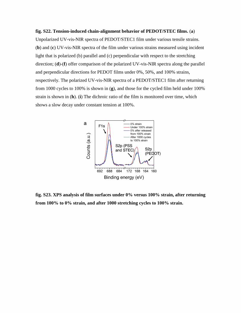
fig. S22. Tension-induced chain-alignment behavior of PEDOT/STEC films. (a)
Unpolarized UV-vis-NIR spectra of PEDOT/STEC1 film under various tensile strains.
(b) and (c) UV-vis-NIR spectra of the film under various strains measured using incident
light that is polarized (b) parallel and (c) perpendicular with respect to the stretching
direction; (d)-(f) offer comparison of the polarized UV-vis-NIR spectra along the parallel
and perpendicular directions for PEDOT films under 0%, 50%, and 100% strains,
respectively. The polarized UV-vis-NIR spectra of a PEDOT/STEC1 film after returning
from 1000 cycles to 100% is shown in (g), and those for the cycled film held under 100%
strain is shown in (h). (i) The dichroic ratio of the film is monitored over time, which
shows a slow decay under constant tension at 100%.
fig. S23. XPS analysis of film surfaces under 0% versus 100% strain, after returning
from 100% to 0% strain, and after 1000 stretching cycles to 100% strain.
section S12. Cycling stability and morphological change of PEDOT with STEC
additives
fig. S24. Cycling stability of PEDOT/STEC1 films. Change in PEDOT/STEC1 film
conductance under various strains for the first 10 cycles between (a) 0 to 50% strain and
(b) 0 to 100% strain. Cycling stability plots are shown in Fig. 2c and d.
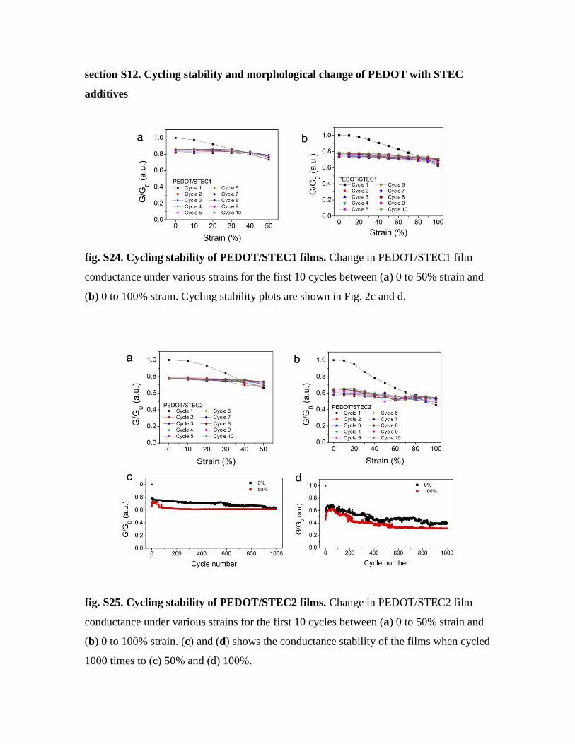
fig. S25. Cycling stability of PEDOT/STEC2 films. Change in PEDOT/STEC2 film
conductance under various strains for the first 10 cycles between (a) 0 to 50% strain and
(b) 0 to 100% strain. (c) and (d) shows the conductance stability of the films when cycled
1000 times to (c) 50% and (d) 100%.
section S13. Mixed ion-electron conductivity
Figure S26, a and b show the typical electrochemical impedance spectra of PEDOT:PSS
with STEC1 in the form of Nyquist plot and bode plot, respectively. The Nyquist plot of
PEDOT:PSS with STEC2 shows an inductive line suggesting that it is almost a pure
electronic conductor. The inductive line in fig. S26a and small decrease of resistance in
high frequency region in fig. S26b are mainly due to the instrumental error. The result
shows that PEDOT:PSS with STEC1 samples (n=3) have resistance of 4.55±0.04 Ω
under ambient conditions (moisture level ~42%).
Figure S26, c and d show the typical electrochemical impedance spectra of PEDOT:PSS
with STEC2 in the form of Nyquist plot and bode plot, respectively. Unlike the
PEDOT:PSS with STEC2 sample, the one semicircle in fig. S26c suggests that
PEDOT:PSS with STEC2 is a mixed electronic/ionic conductive material. The equivalent
circuit of this mixed conductor can be simplified as a parallel combination of electronic
resistance, Re, and ionic resistance, Ri, which is in serial with a capacitor. Then, the
intersection of the high frequency line with the real (Z’) axis is the resistance of the
electronic and ionic resistance in parallel, RiRe/(Ri + Re), and the intersection of the low-
frequency line with the Z’ axis is the electronic resistance, Re (Electrochem. Solid-State
Lett. 2007, 10(3): A65-A69). The result shows that PEDOT:PSS with STEC1 samples
(n=3) possess electronic resistance of 51.5±9.2 Ω and ionic resistance of 68.1±12.7 Ω
under ambient conditions (moisture level ~42%).

fig. S26. Mixed ion-electron conductivity measurements. (a) Electrochemical
impedance spectra of PEDOT:PSS with STEC1 in the form of Nyquist plot. (b) The
variation of the impedance of the PEDOT:PSS with STEC1 to the frequency. (c)
Electrochemical impedance spectra of PEDOT:PSS with STEC2 in the form of Nyquist
plot. (d) The variation of the impedance of the PEDOT:PSS with STEC2 to the frequency.
section S14. PEDOT/STEC as interconnects for FET arrays
The PEDOT/STEC is used as the stretchable interconnect for FET arrays based on rigid-
island structures. As the device density increases (i.e. the ratio of the length of a rigid
island to that of a PEDOT interconnect increases), the actual strain in the PEDOT
interconnects increases monotonically for the same external strain on the entire array.
Figure S27 and Fig. 5D illustrate and summarize such effects through finite element
simulation. For 2 dimensional arrays (e.g. 3×3), the array was clamped between 2 fitted
hollow rings (see Supplementary video 3 for setup) to enable uniform stretching in all
directions. Schematic and calculations for areal strain is shown in fig. S28b. The FET
transfer characteristics are summarized in figs. S29 to S31 for the a high density (5:1
rigid island:interconnect ratio) one-dimensional array under unidirectional stretching, 3×3
two-dimensional array under multi-dimensional stretching on a flat surface, and an
identical 3×3 array under multi-dimensional stretching on a curved surface, respectively.
Table S2 summarizes the mobility and threshold voltage shift at 0% and 125% strain for
the devices show in fig. S30.
fig. S27. Schematic showing the cross-sectional view of a linear rigid-island array
connected with stretchable PEDOT. Schematic showing the cross-sectional view of a
linear rigid-island array connected with stretchable PEDOT. It is used for the finite
element simulation shown in Fig. 5D.

fig. S28. Schematic diagrams illustrating strain calculation for rigid-island devices.
Illustration showing the determination of strain for (a) linear rigid-island arrays under
unidirectional stretching vs. (b) two-dimensional arrays under multidimensional
stretching.

fig. S29. Schematic and transfer characteristics for a 3 × 1 FET array. (a) Top view
schematic of a 3×1 array with a rigid island-to-interconnect ratio of 5:1. (b)-(d) FET
transfer characteristics for the 3 devices under 0%, 100%, and 150% strain.
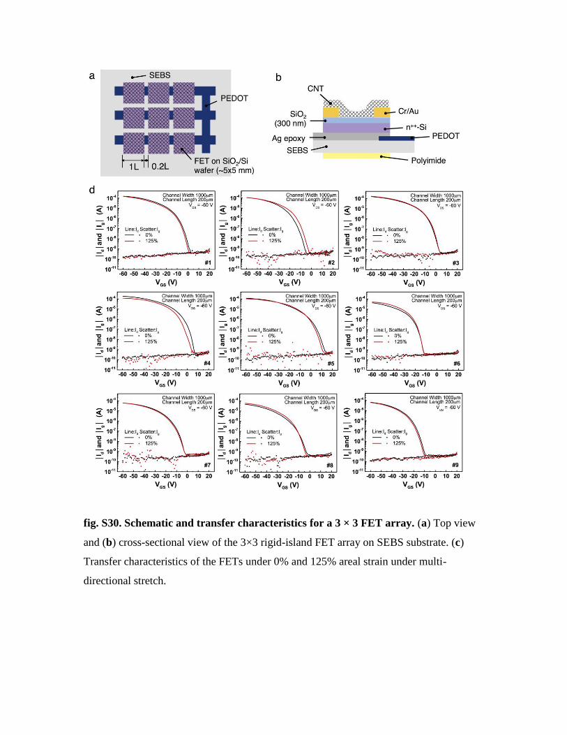
fig. S30. Schematic and transfer characteristics for a 3 × 3 FET array. (a) Top view
and (b) cross-sectional view of the 3×3 rigid-island FET array on SEBS substrate. (c)
Transfer characteristics of the FETs under 0% and 125% areal strain under multi-
directional stretch.
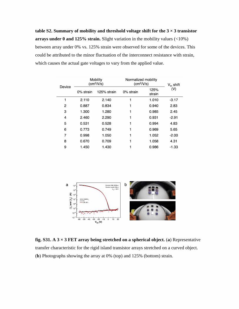
table S2. Summary of mobility and threshold voltage shift for the 3 × 3 transistor
arrays under 0 and 125% strain. Slight variation in the mobility values (<10%)
between array under 0% vs. 125% strain were observed for some of the devices. This
could be attributed to the minor fluctuation of the interconnect resistance with strain,
which causes the actual gate voltages to vary from the applied value.
fig. S31. A 3 × 3 FET array being stretched on a spherical object. (a) Representative
transfer characteristic for the rigid island transistor arrays stretched on a curved object.
(b) Photographs showing the array at 0% (top) and 125% (bottom) strain.
Recommended