1
Supplementary Information
A Flexible and High-Performance All-solid-state Supercapacitor Device Based on
Ni3S2 Nanosheets Coated ITO Nanowire Arrays on Carbon FabricsJie Yang, ab‡ Chun Fang, be‡Chunxiong Bao, ab Weiwei Yang, be Tao Yu, * abc Weidong Zhu, ab Faming Li, ab Jianguo Liu, *de Zhigang Zouabcd
aNational Laboratory of Solid State Microstructures, Nanjing University, Nanjing 210093, P.R.China
bEcomaterials and Renewable Energy Research Center (ERERC) at Department of Physics, Nanjing University, Nanjing
210093, P.R.China
cCollaborative Innovation Center of Advanced Microstructures, Nanjing University, Nanjing 210093, P.R.China
dCollege of Engineering and Applied Science, Nanjing University, Nanjing 210093, P.R.China
e Kunshan Sunlaite New Energy Co., Ltd., Kunshan, 1699 South Zuchongzhi Road, Suzhou, 215347, China
‡ They contribute this work equally.*Address correspondence to [email protected] or [email protected]
Fig. S1 SEM images of L1 (a1, a2, a3), L2 (b1, b2, b3), L3 (c1, c2, c3) in three different
magnifications.
Electronic Supplementary Material (ESI) for RSC Advances.This journal is © The Royal Society of Chemistry 2016
2
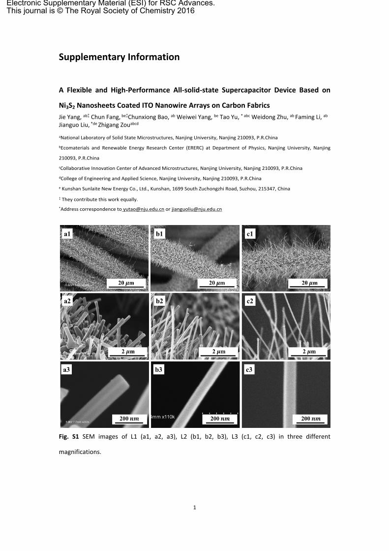
Fig. S2 The HR-TEM of the Ni3S2 coated ITO nanowires.
Fig. S3 XRD patterns of L1, L2, L3.

3
Fig. S4 (a) CV curves of L1@Ni3S2, L2@Ni3S2 and L3@Ni3S2 with the scan rate of 10mV s-1. (b) The
areal capacitances of L1@Ni3S2, L2@Ni3S2 and L3@Ni3S2 at 5mA cm-2.
Table S1 The mass of ITO, Ni3S2 and the mass ratio (Ni3S2/ITO) of the CF@ITO@Ni3S2 with
different electrodeposition cycles based on L2 samples. The areal capacitances, Gravimetric
capacitance based on Ni3S2 mass and Gravimetric capacitancebased on Ni3S2/ITO mass of the
CF@ITO@Ni3S2 with different electrodeposition cycles based on L2 samples.
CF@ITO@Ni3S
2
ITO
(mg cm-2)
Ni3S2
(mg cm-2)
Ni3S2/
ITO
mass
ratio
Areal
capacitance
(F cm-2)
Gravimetric
capacitance
based on Ni3S2
(F g-1)
Gravimetric
capacitance
based on
Ni3S2/ITO
(F g-1)
1 cyc 2.90 0.77 0.266 978.60 1270.90 266.89
2 cyc 2.90 0.96 0.331 1790.40 1865.00 464.39
3 cyc 2.90 1.60 0.552 2505.40 1565.88 557.45
4 cyc 2.90 2.22 0.766 2829.00 1274.32 553.05
5 cyc 2.90 4.12 1.421 3846.40 933.59 548.02
4
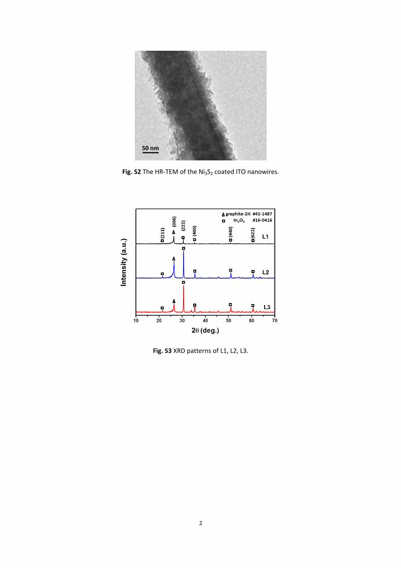
Table S2 The mass of Ni3S2 and the areal capacitances, Gravimetric capacitance based on Ni3S2
for CF@Ni3S2 electrodes with different electrodeposition cycles.
CF@Ni3S2 Ni3S2
(mg cm-2)
Areal
capacitance
(mF cm-2)
Gravimetric
capacitance
based on Ni3S2 (F g-1)
1 cycle 0.15 95.00 633.33
2 cycle 0.42 355.00 845.23
3 cycle 1.07 744.00 695.33
Table S3 The fitted parameters of the EIS data.
Rs (Ω) Rct (Ω) Q1 (F) n1 Q2 (F) n2
CF@ITO@Ni3S2-1cyc 0.4036 1.668 0.001963 0.5159 0.0251 0.9192
CF@ITO@ Ni3S2-2cyc 0.3949 2.036 0.000929 0.5568 0.5576 0.8116
CF@ITO@ Ni3S2-3cyc 0.2566 2.026 0.001406 0.4812 0.6142 0.7634
CF@ITO@ Ni3S2-4cyc 0.5987 1.434 0.006358 0.4146 0.9015 0.7962
CF@ITO@ Ni3S2-5cyc 0.6344 1.715 0.004585 0.4479 0.9997 0.6741
CF@ Ni3S2-1cyc 0.8057 0.267 0.000886 0.7955 0.0694 0.8868
CF@ Ni3S2-3cyc 0.9092 0.318 0.004693 0.5427 0.1315 0.8631
CF@ Ni3S2-5cyc 0.9155 0.273 0.003719 0.6074 0.3764 0.7566
Fig. S5 (a) CV curves as a function of different scan rate for the CF@ITO@Ni3S2 electrodes electrodeposited with 1, 3, 4, 5 cycles.
5
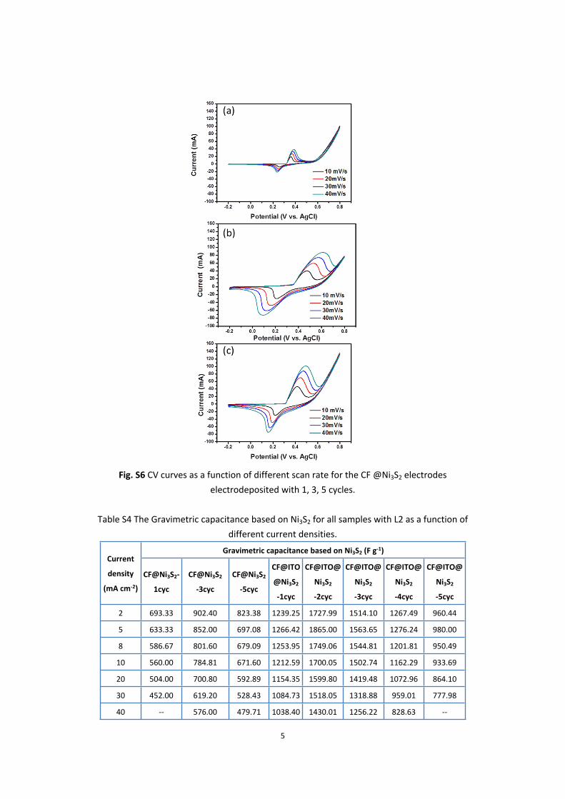
Fig. S6 CV curves as a function of different scan rate for the CF @Ni3S2 electrodes electrodeposited with 1, 3, 5 cycles.
Table S4 The Gravimetric capacitance based on Ni3S2 for all samples with L2 as a function of different current densities.
Gravimetric capacitance based on Ni3S2 (F g-1)Current
density
(mA cm-2)
CF@Ni3S2-
1cyc
CF@Ni3S2
-3cyc
CF@Ni3S2
-5cyc
CF@ITO
@Ni3S2
-1cyc
CF@ITO@
Ni3S2
-2cyc
CF@ITO@
Ni3S2
-3cyc
CF@ITO@
Ni3S2
-4cyc
CF@ITO@
Ni3S2
-5cyc
2 693.33 902.40 823.38 1239.25 1727.99 1514.10 1267.49 960.44
5 633.33 852.00 697.08 1266.42 1865.00 1563.65 1276.24 980.00
8 586.67 801.60 679.09 1253.95 1749.06 1544.81 1201.81 950.49
10 560.00 784.81 671.60 1212.59 1700.05 1502.74 1162.29 933.69
20 504.00 700.80 592.89 1154.35 1599.80 1419.48 1072.96 864.10
30 452.00 619.20 528.43 1084.73 1518.05 1318.88 959.01 777.98
40 -- 576.00 479.71 1038.40 1430.01 1256.22 828.63 --

6
50 -- 552.00 430.99 960.24 1372.00 1174.58 -- --
0 1 2 3 4 5 6 7 80.0
0.5
1.0
1.5
2.0
2.5
3.0
3.5
4.0
-Z'' (
ohm
)
Z' (ohm)
before after
Fig. S7 The EIS curves of the CF@ITO@Ni3S2 electrodes before and after the cyclic stability.
3 4 5 6 7 8
0
5
10
15
20
-Z'' (
ohm
)
Z' (ohm)
beforeafter
Fig. S8 The EIS curves of the CF@ITO@Ni3S2 symmetric device before and after the cyclic stability.
Table S5 The fitted parameters of the EIS data for the CF@ITO@Ni3S2 electrode and symmetric device before and after cyclic stability.
Rs (ohm) Rct (ohm) Q1 (F) n1 Q2(F) n2
Electrode before cyclic stability 0.88 1.41 4.7E-6 0.92 0.0030 0.88
Electrode after cyclic stability 3.67 1.01 1.7E-5 0.79 0.0020 0.88
Device before cyclic stability 4.32 6730 8.4E-4 0.97 0.018 0.92
Device after cyclic stability 5.27 1079 1.4E-3 0.95 0.015 1.3
Recommended